CN102098741A - Method to estimate multiple round trip delays attached to cellular terminals - Google Patents
Method to estimate multiple round trip delays attached to cellular terminals Download PDFInfo
- Publication number
- CN102098741A CN102098741A CN201110063038XA CN201110063038A CN102098741A CN 102098741 A CN102098741 A CN 102098741A CN 201110063038X A CN201110063038X A CN 201110063038XA CN 201110063038 A CN201110063038 A CN 201110063038A CN 102098741 A CN102098741 A CN 102098741A
- Authority
- CN
- China
- Prior art keywords
- signature
- terminal
- base station
- trip delay
- consensus sequence
- Prior art date
- Legal status (The legal status is an assumption and is not a legal conclusion. Google has not performed a legal analysis and makes no representation as to the accuracy of the status listed.)
- Pending
Links
Images


Classifications
-
- H—ELECTRICITY
- H04—ELECTRIC COMMUNICATION TECHNIQUE
- H04W—WIRELESS COMMUNICATION NETWORKS
- H04W56/00—Synchronisation arrangements
- H04W56/0055—Synchronisation arrangements determining timing error of reception due to propagation delay
- H04W56/0065—Synchronisation arrangements determining timing error of reception due to propagation delay using measurement of signal travel time
- H04W56/009—Closed loop measurements
-
- H—ELECTRICITY
- H04—ELECTRIC COMMUNICATION TECHNIQUE
- H04L—TRANSMISSION OF DIGITAL INFORMATION, e.g. TELEGRAPHIC COMMUNICATION
- H04L27/00—Modulated-carrier systems
- H04L27/26—Systems using multi-frequency codes
- H04L27/2601—Multicarrier modulation systems
- H04L27/2647—Arrangements specific to the receiver only
- H04L27/2655—Synchronisation arrangements
- H04L27/2668—Details of algorithms
- H04L27/2673—Details of algorithms characterised by synchronisation parameters
- H04L27/2675—Pilot or known symbols
-
- H—ELECTRICITY
- H04—ELECTRIC COMMUNICATION TECHNIQUE
- H04J—MULTIPLEX COMMUNICATION
- H04J13/00—Code division multiplex systems
- H04J13/0007—Code type
- H04J13/0055—ZCZ [zero correlation zone]
- H04J13/0059—CAZAC [constant-amplitude and zero auto-correlation]
- H04J13/0062—Zadoff-Chu
Abstract
The invention relates to a method to estimate multiple round trip delays attached to cellular terminals. The method for estimating a propagation round trip delay, existing between a base station and a terminal, and comprised within a predetermined round trip delay range, comprises the following steps: transmitting from the base station on a downlink a start order signal (30) to the terminal, after reception by the terminal of the end of the start order signal, sending a signature signal from the terminal to the base station on a uplink, receiving at the base station within a signature receiving time slot (28) the signature signal (34, 38, 42), processing at the base station the received signature signal to provide a round trip delay information. The processing step comprises a cyclic correlation step performed within a fixed correlation time window (54) by using a unique reference sequence (48).
Description
Technical field
The present invention relates to a kind of be used for by on the uplink service multi-path multiplexing frame the RACH signal that receives in the multiplexing dedicated time slot estimate to be attached to the method for a plurality of round-trip delaies of cellular terminal.
Background technology
The cellular communication system of the down link (DL) that comprises up link (UL) from one group of terminal (T) to base station (BS) and each terminal (T) from base station (BS) to this group as UMTS, Random Access Channel (RACH) is provided in time domain as everyone knows, and RACH and up link (UL) business is carried out time-multiplexed.
In up link, insert at random usually and form contrast with the traffic carrying capacity of being scheduled to, wherein utilize timing advance mechanism to make the Traffic Channel close synchronization.
Really, when not having uplink resource (in the time, coding and/or frequency aspect) by base station (BS) when distributing to terminal, this terminal is just used access at random.For example, when terminal is switched on, network is carried out initial access.
In some communication systems (as, utilize OFDM), be useful the synchronous of place, base station up link for strengthening the property, or even operate required.
This utilizes the timing advance method to obtain, the round-trip delay of each terminal of base station measurement (RTD) thus, this round-trip delay depends on the distance between base station (BS) and the terminal (T), and the base station sends the specific timing advance information of terminal to each terminal, so that this terminal moves the data alignment of its uplink data transmission with other uplink terminals that its data and base station (BS) are located.
A kind of known method that is used to measure round-trip delay may further comprise the steps.At first, it is synchronous that terminal (T) is carried out down link (DL), comprises data regularly, frame and Frequency Synchronization.Then, just in time receive predetermined symbol finish after (as, after the first synchronous subframe of down link (DL) frame finishes), the RACH of himself association of terminal transmission, this RACH comprises the leading and possible message that is also referred to as signature at least.At last, base station (BS) detection RACH signs and determines that round-trip delay RTD sends end and the delay between the uplink RACH reception of predetermined process after the duration of terminating stage begins at last as the down link of predetermined symbol.
As everyone knows, the RACH signature is roughly synchronous, in the up link of base station, needs to catch the signature receiving slot carefully, to avoid any undesirable interference to synchronous intended service data.
Under normal conditions, need the consideration type of idling cycle, to avoid this interference that should be minimized as service integration and/or transmission/reception duplex.
When adopting common correlation to handle in time domain, the size of signature receiving slot can not be minimized, and needs simultaneously to limit because slip correlation window or pectination correlation structure are handled the self noise that is produced by correlation.
When utilizing fixing correlation window that the time slot size is minimized, increased by correlation and handled the self noise that is produced.
Present problem is that when adopting the fixed correlation window to minimize the size of signature receiving slot, handling the self noise that is produced by correlation increases, and round-trip delay RTD estimates that accuracy reduces.
Summary of the invention
The objective of the invention is to utilize dimensionally-optimised signature receiving slot that the RTD method of estimation is provided in time domain, this method has improved the accuracy that RTD estimates.
Therefore the present invention relates to [claim 1].
According to specific embodiment, be used to estimate that the method for propagating round-trip delay comprises one or more following features: [dependent claims 2 to 15].
The invention still further relates to communication system [claim 16].
According to specific embodiment, this communication system comprises one or more following features: [dependent claims 17 to 18].
Description of drawings
Can better understand the present invention by reading the description that only provides as an example below with reference to accompanying drawing, wherein:
Fig. 1 is the structure that adopts the mobile communication system of single terminal.
Fig. 2 is the communication flow diagram that has the zoomed-in view of up link and descending chain circuit frame in the base station level.
Fig. 3 is the data structure of signature sequence.
Fig. 4 has to be positioned at detailed views three diverse locations and signature receiving slots corresponding three the stack signatures of same terminal.
Fig. 5 is the first embodiment flow chart that is used to estimate in the method for the round-trip delay of the base station of unit/terminal mobile communication system level.
Fig. 6 is the second embodiment flow chart that is used to estimate in the method for the round-trip delay of the base station of unit/terminal mobile communication system level.
Fig. 7 illustrates the correlation amplitude of the method acquisition that utilizes shown in Fig. 5 or 6 and the figure of time relation.
Fig. 8,9 and 10 is three structure charts that adopt the mobile communication system of three terminals.
Figure 11 is the communication flow diagram of three overlaying structures that has the zoomed-in view of up link and descending chain circuit frame in the base station level.
Figure 12 is the schematic diagram that the mode of setting up three signature sequences is shown.
Figure 13,14,15 is data structures of three signature sequences.
Figure 16 is the detailed view of the amplification of signature receiving slot, and wherein the signature of three of all receptions system configurations is applied.
Figure 17 is in using the system of three terminals, is used for estimating together the first embodiment flow chart of the method for each round-trip delay and host ID.
Figure 18 is in using the system of three terminals, is used for estimating together the second embodiment flow chart of the method for each round-trip delay and host ID.
Figure 19 illustrates the correlation amplitude of the method acquisition that utilizes shown in Figure 17 or 18 and the figure of time relation.
Figure 20 illustrates at the correlation amplitude of utilizing the method acquisition shown in Figure 17 or 18 of the system that adopts asynchronous and synchronous terminal and the figure of time relation.
Embodiment
In Fig. 1, show three structures of unit/terminal mobile communication system 2.Unit/terminal mobile communication system 2 comprises user terminal 4 that is expressed as T1 and the base station 6 that is expressed as BS.In first structure, terminal 4 is positioned at the primary importance place that is expressed as P1.In second structure, terminal 4 is positioned at the second place place that is expressed as P2.In the 3rd structure, terminal 4 is positioned at the 3rd position that is expressed as P3.Because P1 is near BS, so P2 is far away from BS, and P3 from BS farthest.
At each position P1, P2, the P3 place, terminal 4 can receive the identical down link signal 8 that sends from BS, but has different propagation path delay.
At each position P1, P2, the P3 place, terminal can send corresponding uplink signal 10,12 and 14.
Receive the required time-dependent of identical data again in the distance of two paths for base station 6 to move 4 transmission data and when terminal 4 receives, retransmit base station 6, back at once, and be represented as round-trip delay RTD.
With P1, P2, the corresponding round-trip delay of P3 is expressed as round-trip delay RTD1 respectively, RTD2 and RTD3, and RTD1<RTD2<RTD3.
Here the maximum coverage range that is limited by position P3 defines the sub-district 16 that service is provided by base station 6, and can be characterized by round-trip delay RTD3.
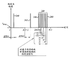
In Fig. 2, show the data structure of down link 18 and up link 20, the time that wherein is attached to axis of abscissas flows to right from a left side.Descending chain circuit frame 18 is the time-multiplexed of several traffic data pulses 22 and evenly spaced lock-out pulse, only shows a lock-out pulse 24 here.The uplink frame 20 at 8 level places is intended service amount data 26 and evenly spaced RACH(Random Access Channel in the base station) receiving slot 28 time-multiplexed.Because the useful part as the RACH of the synchronizing characteristics of considering is that it is leading, is also referred to as signature, therefore from will only signature being described here.
In order to make that terminal 4 can be synchronous with base station 6 in up link, after the end signal 30 of propagating the lock-out pulse 24 that sends from BS and when receiving, might be after predetermined lasting time, terminal 4 sends the signature that is expressed as SGN1 at its data structure, described signature is according to terminal P1, the delivering position of P2 and P3 is expressed as 32,36 and 40 respectively.According to terminal location, the signature SGN1 that receives in signature receiving slot 28 is carried out the difference location, and work as from being positioned at P1, when the terminal at P2 and P3 place was sent, described signature SGN1 was expressed as 34,38 and 42 respectively.May be after the predetermined lasting time of terminating stage, the initial order time 30 of lock-out pulse 24 and the time difference between the reception of the signature SGN1 at 6 grades of places, base station finishes equal the round-trip delay of terminal 4.Correspond respectively to and receive signature 34(and represent with solid box), 38(represents with dotted box) and 42(show with the double dot dash line frame table) round-trip delay be round-trip delay RTD1, RTD2 and RTD3.In Fig. 2, in the pedestal of distance base station distance and time relation curve, show the terminal propagation path of signature with bold line.
In Fig. 3, show the data structure 44 of signature SGN1.Signature SGN1 comprises one group of data 46, and these group data can be divided into the consensus sequence 48 that is expressed as SEQB1 and be expressed as the cyclic extensions 52 of SGN1-T, the afterbody of its SGN1 that can be considered to sign.
The head 50 of consensus sequence SEQB1 is from a
 To a
To a
 Data sequence, cyclic extensions SGN1-T has the data structure identical with head part S GN1-H.In modification, cyclic extensions can be positioned at the head of signature and have identical data structure with the afterbody of this sequence.
Here, this sequence is CAZAC(constant amplitude zero auto-correlation) sequence, the Zadoff Chu sequence of more specifically saying so is defined as:

And
 , wherein r and N are relatively prime.
The CAZAC sequence has periodic auto-correlation function, and it is unit pulse function (Dirac function).When the needs high power transmission, constant amplitude can realize that excellent protection is to avoid non-linear.
As modification, also can adopt sequence ZAC(zero auto-correlation).
In Fig. 4, show signature receiving slot 28, it has and is positioned at three diverse location P1, three stack signatures 34,36 and 38 corresponding to same terminal T1 of P2 and P3.Signature receiving slot 28 is provided with so that comprise the signature 34,36 and 38 of all receptions on the whole, covers whole round-trip delay scope thus.Signature receiving slot 28 comprises fixing in time correlation time window 54, and its length equals the consensus sequence length N, and wherein carries out circular correlation and handle.The time started 56 of this relevant treatment is corresponding to the right-hand member of the correlation time window among Fig. 4.Distribute to terminal 4 signature 34 reception zero-time 58 corresponding to the signature receiving slot 28 right-hand member, described terminal 4 is positioned at the position very near from the base station.Define n idling cycle 60 by the time 56 and 58 time intervals of being defined.Idling cycle 60 may be essential with avoid signing or RACH to the interference of intended service amount data.
The cyclic extensions 52 of sequence SEQB1 is guaranteed for the signature 34,36,38 that is included in any reception in the correlation time window 54, receives one group of consensus sequence data that circulation is complete.
Therefore, the signed data that is included in any reception in the correlation window 54 is the cyclic shift consensus sequence that obtains from SEQB1.
Determine that the cyclic shift consensus sequence provides the corresponding round-trip delay of being experienced by terminal T1 with respect to the cyclic shift of consensus sequence SEQB1.
As seeing in Fig. 4, the maximum round trip delay RTD3 of signature 38 equals the length of cyclic extensions 52, and it also is included in the cyclic shift of the signed data in the correlation time window.
The flow chart of Fig. 5 shows first embodiment that is used to estimate in the method 62 of the round-trip delay at the base station BS level place of unit/terminal mobile communication system 2.
In the first step 64, in signature receiving slot 28, receive complete signature SGN1 after, in step 65, removal is positioned at the sampling of the signature SGN1 that is received outside the correlation time window 54.
Then, in following steps 66, circular correlation is carried out in remaining sampling, remaining sampling is imported in the circular shift register as the sequence that initial zero displacement filtering receives.
In step 67, at first be set to 1 and come initialization shift counter ic by shift counter ic value.Then, in step 68, sequence and unique consensus sequence SEQB1 that ic-1 displacement filtering is received carry out the summation that the product of sampling is taken advantage of in sampling.By step 69, the sum of products that obtains by step 68
 Be stored in down be designated as ic-1 from the array of 1 to N-1 mark.After the
 step 69 is step 70, wherein actual count device value ic and N is compared.
If ic is not equal to N, Counter Value ic increases by 1 in step 71, and the sequence that the actual shift in ring register receives is shifted a sampling period.Then, execution in step 68,69 and 70 once more.
If ic equals N, continue execution in step 74, detect correlation peaks as sum of products array
 Maximum.In step
 76, in the sum of products
 During for maximum
 The round-trip delay of estimation of the value signature SGN1 that is confirmed as receiving, it is represented as t (SGN1).
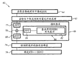
In a second embodiment, the method 62 shown in the flow chart of Fig. 6 comprises the step 64 of same sequence, 65,66,74 and 76, and except the step 66, other step is all identical, wherein continuous execution in step 77,78 and 80.In step 77, a FFT(fast Fourier transform) will be transformed into the sampling that receives at frequency domain from the time-domain sampling that step 65 obtains.Then in step 78, the corresponding frequency domain sample of the consensus sequence SEQB1 that is obtained by step 80 is multiply by in the frequency domain transform sampling.In step 80, in time domain, after the input reference sequence SEQB1, carrying out the 2nd FFT by step 84 by step 80.After two FFT results are multiplied each other, then carry out the IFFT(Fast Fourier Transform Inverse) by step 80.
In Figure 86 of Fig. 7, the correlation amplitude and the time relation of three structures among Fig. 1 described.
Fig. 8,9 and 10 show three structures of the mobile communication system of using three different terminals 4,94 and 98, and described terminal 4,94 and 98 is represented as T1, and T2 and T3 use solid line respectively, and dotted line and double dot dash line square surround.
In first structure 93 shown in Figure 8, terminal 4(T1) be positioned at the P1 place, and terminal 94(T2) and terminal 96(T3) lay respectively at P2 and P3 place.Distribute to T1, the corresponding up link of T2 and T3 is expressed as 98,100 and 102.In first structure 93, corresponding to terminal T1, the round-trip delay of T2 and T3 is respectively round-trip delay RTD1, RTD2 and RTD3.
In second structure 103 shown in Figure 9, terminal 4(T1) be positioned at the P3 place, and terminal 94(T2) and terminal 96(T3) lay respectively at P1 and P2 place.Distribute to T1, the corresponding up link of T2 and T3 is expressed as 108,104 and 106.In second structure 103, corresponding to terminal T1, the round-trip delay of T2 and T3 is respectively round-trip delay RTD3, RTD1 and RTD2.
In the 3rd structure 110 shown in Figure 10, terminal 4(T1) be positioned at the P2 place, and terminal 94(T2) and terminal 96(T3) lay respectively at P3 and P1 place.Distribute to T1, the corresponding up link of T2 and T3 is expressed as 114,116 and 112.In the 3rd structure 110, corresponding to terminal T1, the round-trip delay of T2 and T3 is respectively round-trip delay RTD2, RTD3 and RTD1.
In Figure 11, show down link 18 and up link 20 data structures in the mode identical with Fig. 2.
About first structure 93, in order to make terminal 4,94,96 is synchronous with base station 6 in up link, after the initial order signal 30 of the lock-out pulse 24 that will send from BS is propagated and when receiving initial order 30, might be after predetermined lasting time, each terminal 4,94 and 96 send the signature that is associated, described signature is represented as SGN1 at its data structure, and SGN2 and SGN3 (are P1 at the relevant position of its terminal, P2 and P3) be represented as 118,122 and 126.Each SGN1 that signs, SGN2 and SGN3 are received in signature receiving slot 28, are differently located according to terminal location, and when from laying respectively at P1, when each terminal 4,94 and 95 at P2 and P3 place is sent, signature SGN1, SGN2 and SGN3 are expressed as 120,124 and 128 respectively.May be after the predetermined lasting time of terminating stage, at initial order time 30 and each signature SGN1 of the lock-out pulse 24 of base station level, the time difference between the reception of SGN2 and SGN3 finishes equals the round-trip delay of terminal 4,94 and 96 respectively.Corresponding respectively to the signature 120,124 of reception and 128 round-trip delay is round-trip delay RTD1, RTD2 and RTD3.In Figure 11, in two pedestals, show the terminal propagation path of signature with bold line, the longitudinal axis is represented the distance apart from the base station, the transverse axis express time.
Here, in signature receiving slot 28, only show the signature 120,124 and 128 of the reception of first structure 93.
About second structure 103, only show the signature 130,132 and 134 of transmission, it is expressed as SGN2 respectively, SGN3 and SGN1, respectively by T2, T3 and T1 are from P1, and P2 and P3 send.
About the 3rd structure 110, only show the signature 136,138 and 140 of transmission, it is expressed as SGN3 respectively, SGN1 and SGN2, respectively by T3, T1 and T2 are from P1, and P2 and P3 send.
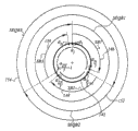
Figure 12 shows the mode of foundation from three signature sequences of consensus sequence SEQB1 acquisition.Consensus sequence SEQB1 deasil is arranged on the reference rings 142.Consensus sequence SEQB1 is divided into and is expressed as SB1, and three continuous subsequences 146,148 of SB2 and SB3 and 150 suppose that N is 3 integral multiple.
SB1 comprise scope from
 Arrive
 One group of data.SB2 be scope from
Arrive
One group of data.SB2 be scope from
Arrive
 One group of data.SB3 be scope from
Arrive
One group of data.
One group of data.SB3 be scope from
Arrive
One group of data.
The first signature sequence SEQB1 is a consensus sequence, and can be described to one group of continuous subsequence SB1, SB2 and SB3.
Be expressed as SEQB3 the 3rd signature sequence 154 and be defined as one group of continuous subsequence SB3, SB1 and SB2.
At Figure 13, sequence SEQB1, SEQB2 and the SEQB3 of linear expansion described in 14 and 15 respectively.All sequences all is mutually orthogonal.
The foundation of signature SGN1 has more than been described.To set up SGN2 and SGN3 with the above-mentioned identical mode of SGN1.
In Figure 16, show signature receiving slot 28, wherein to the signature 118,138,134,130,122,140,136,132 of all receptions of three system configurations, 126 superpose.In the rectangle that with the solid line is the boundary, surrounded the signature of first structure 93.In the rectangle that with the dotted line is the boundary, surrounded the signature of second structure.In the rectangle that with the double dot dash line is the boundary, surrounded the signature of the 3rd structure.
Actual reception should be counted as the line of the same type that surrounds signature.For example, under the situation of first structure, in actual reception, will only illustrate 118,122 and 126.
Signature cyclic extensions 52,156 and 158 is respectively each signature SGN1, the signature afterbody of SGN2 and SGN3.All signature expansions have identical length.
In modification, the signature cyclic extensions can be respectively each signature SGN1, the signature head of SGN2 and SGN3.
The flow chart of Figure 17 shows the mobile communication system that is used for using three terminals, closes first embodiment of the method for estimating each round-trip delay and host ID at base cascade.
In the first step 162, after the summation SGN1+SGN2+SGN3 that is born the signature in receiving signature reception crack 28, in step 164, remove the sampling of the signature summation SGN1+SGN2+SGN3 that is positioned at the reception outside the correlation time window 54.
Then, in following steps 166, circular correlation is carried out in remaining sampling, remaining sampling is imported in the circular shift register as the signal that initial zero displacement filtering receives.
In step 166, at first, in step 168, this shift counter ic is set by shift counter ic value is made as 1.Then, in step 170, displacement receives to ic-1 sequence and consensus sequence SEQB1 carry out the summation that the product of sampling is taken advantage of in sampling.By step 172, the sum of products that obtains by step 170
 Be stored in down be designated as ic-1 from the array of 1 to N-1 mark.After the
 step 172 is step 180, wherein actual count device value ic and N is compared.
If ic is not equal to N, Counter Value ic increases by 1 in step 182, and the signal that the actual shift in the ring register receives is shifted a sampling period.Then, execution in step 170,172 and 180 once more.
If ic equals N, continue execution in step 186, detect three correlation peaks as correlation sum of products array
Three peaks, the corresponding signature of each peak value.This signature is a host ID of distributing to each terminal.In step 188, three values of ic when the sum of products is maximum are confirmed as belonging to one of three time intervals relevant with signature, and for each detected signature, with round-trip delay be defined as signing peak value time index (time index) and do not have time difference between the expectation subscript of same signature of round-trip delay.
Figure 18 is second embodiment that is used in the method for mobile communication system sense terminals identification code that uses three different terminals and round-trip delay.
In this embodiment, method 160 comprises except step 166, with the step 162 of the first embodiment same sequence, and 164,186 and 188, wherein carry out different steps 190,192 and 194 continuously.In step 190, a FFT(fast Fourier transform) will be transformed into the sampling that frequency domain receives from the time-domain sampling that step 164 obtains.Then in step 192, the corresponding sampling of the consensus sequence SEQB1 in the frequency domain that obtains by step 196 is multiply by in the sampling that receives in the frequency domain.In step 196, in time domain, after the input reference sequence SEQB1, carrying out the 2nd FFT by step 200 by step 198.After two FFT results are multiplied each other, then carry out the IFFT(Fast Fourier Transform Inverse) by step 194 pair resulting sampling.
Figure 19 shows the correlation amplitude and the time relation of the signature of three used terminals of three system configurations being applied.In the figure of Figure 19, solid line, the correlation peaks of the first, the second and the 3rd structure has been described in dotted line and double dot dash line respectively.Line 220,222 and 224 has been described the temporal correlation of the first, the second and the 3rd signature that is used for first structure respectively.Line 226,228 and 230 has been described the temporal correlation of the first, the second and the 3rd signature that is used for second structure respectively.Line 232,234 and 236 has been described the temporal correlation of the first, the second and the 3rd signature that is used for the 3rd structure respectively.As can be seen, can limit the time interval of distributing to signature respectively.Therefore, here
Be assigned to SGN1,
 Be assigned to SGN2,
 Be assigned to SGN3.The time index of the signature that the round-trip delay of measuring for the signature of each reception equals to receive deducts the time index of the expectation of the same signature with any delay, and it is 1 for SGN1, is N/3 for SGN2, is 2N/3 for SGN3.
In practical operation, will three lines of the same type only be shown.As an example, under the situation of first structure, the round-trip delay of correlation peaks line 220 expression RTD1, and line 222 and 224 is represented the round-trip delay of RTD2 and RTD3 respectively.
Any overlapping for fear of in the testing process of the adjacent signature of circulation, occurring, should be when design unusual attention, utilize the desired maximum round trip delay of communication system that two adjacent signatures are spaced apart at least.In said system, this spacing will be greater than round-trip delay RTD3.
Figure 20 shows the correlation amplitude and the time relation of the said method of following the system that is used to comprise uplink synchronisation terminal and the asynchronous terminal of up link.
Here, two asynchronous signatures are distributed to two asynchronous terminals, first terminal is set shows round-trip delay RTD1, second terminal is set shows round-trip delay RTD2.Asynchronous signature means that sending this signature is used for initial access.
One group of synchronization signatures is distributed to one group of uplink synchronisation terminal.Synchronization signatures mean when terminal always with up link in the base station time synchronized time send this signature, that is, the timing advance value is available in this terminal.
Here, will be as the signature sequence of the structure core of first synchronization signatures of synchronous terminal formation sequence displacement 2N/3 with respect to the first asynchronous signature.The signature subsequently of any synchronous terminal has the formation sequence that has been shifted the value in the scope of being included in [2N/3, N-1] with respect to consensus sequence.
The first and second asynchronous signatures all provide time delay and terminal iidentification.
In Figure 20, this Figure illustrates the first correlation peaks line 240 corresponding to the first asynchronous signature with round-trip delay RTD1.
This figure has also described the second correlation peaks line 244 corresponding to the second asynchronous signature with round-trip delay RTD2.
This figure has also described one group of correlation peaks line 244(first line 246 that does not have the synchronization signatures of round-trip delay RTD corresponding to a group, the last item line 260).
The importance of separating signature (synchronous or asynchronous) in two various process is, for synchronous situation, owing to no longer consider any round-trip delay, therefore the cyclic shift of difference signature closer can be merged.
In this case, except low cyclic shift step, can also adopt the low cyclic extensions duration, and can suppress idling cycle.For the maximum path to channel postpones, timing advance sum of errors filter effect is handled, and the reply cyclic extensions duration is selected.
The low circulation crossing dependency that adopts several selected CAZAC consensus sequences to obtain each other also is favourable.Therefore, the complexity that the number of the number of available signatures and consensus sequence is multiplied each other and can bring the interference between the sequence and increase receiver.The latter is owing to needing a plurality of correlators (one of each benchmark CAZAC sequence) rather than single correlator to cause in the base station when only using a consensus sequence.
This good example with basic sequence group of good circulation crosscorrelation performance is that the clockwise and counterclockwise phase place rotatable sequence of being inferred by original Zadoff Chu sequence is right.


And
, wherein r and N are relatively prime.
Because second consensus sequence is obtained by first consensus sequence, so this example needs the limited storage of consensus sequence.Therefore the specific uniqueness that has kept benchmark.
Claims (10)
1. be used in communication system signature signal (118,122,126) from a plurality of terminals (4,94,96) be sent to the method for base station (6), described communication system comprises uses a plurality of signature sequences (48,152,154) the described a plurality of terminals that communicate with described base station, described signature signal (118,122,126) can be used to estimate to propagate round-trip delay at place, described base station, described propagation round-trip delay depends on the distance between described base station and a plurality of terminal
The described method of carrying out in each end comprises the following steps:
Generate signature signal in end,
Send signature signal so that receive signature signal from terminal by described base station (6),
It is characterized in that, described a plurality of signature sequence (48,152,154) has following correlation, promptly under the selected situation as consensus sequence (48) of in described a plurality of signature sequences, other signature sequences comprise the sequence that obtains from described consensus sequence (48).
2. method according to claim 1 is characterized in that, each in described a plurality of signature sequences is one group of continuous data.
3. according to any one described method among the claim 1-2, it is characterized in that described signature signal also comprises cyclic extensions (52,156,158), described cyclic extensions (52,156,158) is shorter than the length of described consensus sequence (48).
4. according to any one described method among the claim 1-3, it is characterized in that described signature signal comprises cyclic extensions, described cyclic extensions has the identical data structure of a part with described consensus sequence (48).
5. according to any one described method among the claim 1-4, it is characterized in that described a plurality of signature sequences (48,152,154) are the cyclic shifts of described consensus sequence (48).
6. be used for signature signal being sent to the terminal (4 of base station (6) in communication system, 94,96), described communication system comprises uses a plurality of signature sequences (48,152,154) a plurality of terminals that communicate with described base station, described signature signal can be used to locate to estimate to propagate round-trip delay in described base station (6), described propagation round-trip delay depends on the distance between described base station and the described terminal, and described terminal comprises:
Be used for generating the generating apparatus of described signature signal in described end,
Be used for described signature signal is sent to the dispensing device of described base station from described terminal,
It is characterized in that, described a plurality of signature sequence (48,152,154) has following correlation, promptly under the selected situation as consensus sequence (48) of in described a plurality of signature sequences, other signature sequences comprise the sequence that obtains from described consensus sequence (48).
7. terminal according to claim 6 is characterized in that, each in described a plurality of signature sequences is one group of continuous data.
8. according to any one described terminal among the claim 6-7, it is characterized in that described signature signal also comprises cyclic extensions (52,156,158), described cyclic extensions (52,156,158) is shorter than the length of described consensus sequence (48).
9. according to any one described terminal among the claim 6-8, it is characterized in that described signature signal comprises cyclic extensions, described cyclic extensions has the data structure identical with the part of described consensus sequence.
10. according to any one described terminal among the claim 6-9, it is characterized in that described a plurality of signature sequences (48,152,154) are the cyclic shifts of described consensus sequence (48).
Applications Claiming Priority (2)
| Application Number | Priority Date | Filing Date | Title |
|---|---|---|---|
| EP06290717.5 | 2006-05-04 | ||
| EP06290717A EP1852981B1 (en) | 2006-05-04 | 2006-05-04 | Method to estimate multiple round trip delays attached to cellular terminals from a RACH signal received within a dedicated time slot multiplexed onto an uplink traffic multiplex frame. |
Related Parent Applications (1)
| Application Number | Title | Priority Date | Filing Date |
|---|---|---|---|
| CN2007101288586A Division CN101072448B (en) | 2006-05-04 | 2007-04-30 | Method to estimate multiple round trip delays attached to cellular terminals |
Publications (1)
| Publication Number | Publication Date |
|---|---|
| CN102098741A true CN102098741A (en) | 2011-06-15 |
Family
ID=36954713
Family Applications (2)
| Application Number | Title | Priority Date | Filing Date |
|---|---|---|---|
| CN201110063038XA Pending CN102098741A (en) | 2006-05-04 | 2007-04-30 | Method to estimate multiple round trip delays attached to cellular terminals |
| CN2007101288586A Active CN101072448B (en) | 2006-05-04 | 2007-04-30 | Method to estimate multiple round trip delays attached to cellular terminals |
Family Applications After (1)
| Application Number | Title | Priority Date | Filing Date |
|---|---|---|---|
| CN2007101288586A Active CN101072448B (en) | 2006-05-04 | 2007-04-30 | Method to estimate multiple round trip delays attached to cellular terminals |
Country Status (6)
| Country | Link |
|---|---|
| US (1) | US20070259693A1 (en) |
| EP (2) | EP1852981B1 (en) |
| JP (2) | JP2007312380A (en) |
| CN (2) | CN102098741A (en) |
| AT (1) | ATE445937T1 (en) |
| DE (1) | DE602006009767D1 (en) |
Cited By (1)
| Publication number | Priority date | Publication date | Assignee | Title |
|---|---|---|---|---|
| CN103581944A (en) * | 2012-08-07 | 2014-02-12 | 华为技术有限公司 | Ultrahigh-speed random access processing method, device and system |
Families Citing this family (16)
| Publication number | Priority date | Publication date | Assignee | Title |
|---|---|---|---|---|
| US8081617B2 (en) * | 2006-08-03 | 2011-12-20 | Panasonic Corporation | Radio transmitting apparatus and radio transmitting method |
| US20090247087A1 (en) * | 2008-03-26 | 2009-10-01 | Qualcomm Incorporated | Methods and apparatus for measuring round-trip delay at a mobile station |
| US8693305B2 (en) * | 2009-08-24 | 2014-04-08 | Qualcomm Incorporated | Method and apparatus for detecting OFDM signals in the presence of frequency orthogonal OFDM interferers |
| US20110194630A1 (en) * | 2010-02-10 | 2011-08-11 | Yang Hua-Lung | Systems and methods for reporting radio link failure |
| DE102011117283A1 (en) | 2011-10-31 | 2013-05-02 | Merkur Media GmbH | Method for transmitting information |
| CN103298136B (en) * | 2012-02-29 | 2016-11-23 | 华为技术有限公司 | A kind of accidental access method, terminal, base station and system |
| US9726748B2 (en) | 2012-09-21 | 2017-08-08 | Qualcomm Incorporated | Cyclic shift delay detection using signaling |
| US10177915B2 (en) | 2013-03-15 | 2019-01-08 | Ologn Technologies Ag | Systems, methods and apparatuses for device attestation based on speed of computation |
| US9698991B2 (en) | 2013-03-15 | 2017-07-04 | Ologn Technologies Ag | Systems, methods and apparatuses for device attestation based on speed of computation |
| US9456344B2 (en) | 2013-03-15 | 2016-09-27 | Ologn Technologies Ag | Systems, methods and apparatuses for ensuring proximity of communication device |
| WO2014181313A1 (en) * | 2013-05-10 | 2014-11-13 | Ologn Technologies Ag | Ensuring proximity of wifi communication devices |
| GB2515801A (en) * | 2013-07-04 | 2015-01-07 | Sony Corp | Transmitter and receiver and methods of transmitting and receiving |
| US9455998B2 (en) | 2013-09-17 | 2016-09-27 | Ologn Technologies Ag | Systems, methods and apparatuses for prevention of relay attacks |
| CN105636098B (en) * | 2014-10-30 | 2020-03-13 | 中兴通讯股份有限公司 | Method and device for estimating waiting time delay of uplink service |
| ES2738861T3 (en) * | 2014-11-06 | 2020-01-27 | Fujitsu Ltd | Wireless communication system, base station, terminal device and processing method |
| US11889436B2 (en) * | 2020-08-17 | 2024-01-30 | Qualcomm Incorporated | Calibration of group delay in a mobile device |
Family Cites Families (8)
| Publication number | Priority date | Publication date | Assignee | Title |
|---|---|---|---|---|
| US5959980A (en) * | 1995-06-05 | 1999-09-28 | Omnipoint Corporation | Timing adjustment control for efficient time division duplex communication |
| US7031295B2 (en) * | 1996-11-07 | 2006-04-18 | Harris Corporation | System and method for minimizing guard time in a time division duplex communication system |
| DE59914258D1 (en) * | 1998-06-25 | 2007-05-03 | Philips Intellectual Property | Wireless network |
| US6735221B1 (en) * | 1999-01-11 | 2004-05-11 | International Business Machines Corporation | Communication network system |
| JP3413833B2 (en) * | 2000-05-18 | 2003-06-09 | 日本電気株式会社 | Access control method and base station device |
| JP3415579B2 (en) * | 2000-11-09 | 2003-06-09 | 松下電器産業株式会社 | Matched filter and correlation detection calculation method |
| US7321645B2 (en) | 2003-08-29 | 2008-01-22 | Lucent Technologies Inc. | Method and arrangement for detecting a random access channel preamble using multiple antenna reception in a communication system |
| US20070183386A1 (en) * | 2005-08-03 | 2007-08-09 | Texas Instruments Incorporated | Reference Signal Sequences and Multi-User Reference Signal Sequence Allocation |
-
2006
- 2006-05-04 EP EP06290717A patent/EP1852981B1/en active Active
- 2006-05-04 DE DE602006009767T patent/DE602006009767D1/en active Active
- 2006-05-04 AT AT06290717T patent/ATE445937T1/en not_active IP Right Cessation
- 2006-05-04 EP EP09167908A patent/EP2114104A3/en not_active Withdrawn
-
2007
- 2007-04-30 CN CN201110063038XA patent/CN102098741A/en active Pending
- 2007-04-30 CN CN2007101288586A patent/CN101072448B/en active Active
- 2007-05-01 US US11/742,876 patent/US20070259693A1/en not_active Abandoned
- 2007-05-02 JP JP2007121742A patent/JP2007312380A/en active Pending
-
2011
- 2011-03-29 JP JP2011073068A patent/JP2011193476A/en active Pending
Cited By (6)
| Publication number | Priority date | Publication date | Assignee | Title |
|---|---|---|---|---|
| CN103581944A (en) * | 2012-08-07 | 2014-02-12 | 华为技术有限公司 | Ultrahigh-speed random access processing method, device and system |
| CN103581944B (en) * | 2012-08-07 | 2016-12-07 | 华为技术有限公司 | Ultrahigh speed random access processing method, Apparatus and system |
| US9674872B2 (en) | 2012-08-07 | 2017-06-06 | Huawei Technologies Co., Ltd. | Method, apparatus and system for processing very-high-speed random access |
| US10039133B2 (en) | 2012-08-07 | 2018-07-31 | Huawei Technologies Co., Ltd. | Method, apparatus and system for processing very-high-speed random access |
| US10485031B2 (en) | 2012-08-07 | 2019-11-19 | Huawei Technologies Co., Ltd. | Method, apparatus and system for processing very-high-speed random access |
| US10827533B2 (en) | 2012-08-07 | 2020-11-03 | Huawei Technologies Co., Ltd. | Method, apparatus and system for processing very-high-speed random access |
Also Published As
| Publication number | Publication date |
|---|---|
| CN101072448A (en) | 2007-11-14 |
| DE602006009767D1 (en) | 2009-11-26 |
| CN101072448B (en) | 2012-09-05 |
| ATE445937T1 (en) | 2009-10-15 |
| EP1852981B1 (en) | 2009-10-14 |
| US20070259693A1 (en) | 2007-11-08 |
| EP1852981A1 (en) | 2007-11-07 |
| EP2114104A3 (en) | 2011-01-12 |
| EP2114104A2 (en) | 2009-11-04 |
| JP2011193476A (en) | 2011-09-29 |
| JP2007312380A (en) | 2007-11-29 |
Similar Documents
| Publication | Publication Date | Title |
|---|---|---|
| CN101072448B (en) | Method to estimate multiple round trip delays attached to cellular terminals | |
| CN101536336B (en) | Method and apparatus for fast cell search | |
| KR102198350B1 (en) | Syncronization control method for data transmission/receipt and station for data transmission/receipt syncronization | |
| US8064546B2 (en) | Random access preamble detection for long term evolution wireless networks | |
| JP5358701B2 (en) | Method and apparatus for selecting and transmitting random access preamble | |
| CN101641925B (en) | Method for setting cyclic shift considering frequency offset | |
| JP5023881B2 (en) | Mobile communication system, signal transfer method, and receiver | |
| US20080317184A1 (en) | Method for transmitting synchronization signal in mobile multimedia system | |
| KR100521135B1 (en) | System and method for ranging in OFDMA system | |
| TW200841660A (en) | System and methods for rapid uplink air interface synchronization | |
| CN113315733B (en) | Time-frequency synchronization method, communication system and storage medium | |
| EP1909446A2 (en) | Mobile communication system and its signal transfer method | |
| KR100632292B1 (en) | Pilot Signal Forming Method, Cell Search Method, and Apparatus for Cell Search in Orthogonal Frequency Division Multiple Communication System | |
| EP1845645A1 (en) | Base station apparatus, radio transmission system, radio base station program, and timing estimating method | |
| CN101615921B (en) | Method and device for detecting ascending time migration of mobile station | |
| RU2459354C1 (en) | Method to assess bearing frequency shift in up-link for wireless telecommunications systems |
Legal Events
| Date | Code | Title | Description |
|---|---|---|---|
| C06 | Publication | ||
| PB01 | Publication | ||
| C10 | Entry into substantive examination | ||
| SE01 | Entry into force of request for substantive examination | ||
| C02 | Deemed withdrawal of patent application after publication (patent law 2001) | ||
| WD01 | Invention patent application deemed withdrawn after publication |
Application publication date: 20110615 |