CN102096179B - Zoom lens and image pickup apparatus including the same - Google Patents
Zoom lens and image pickup apparatus including the same Download PDFInfo
- Publication number
- CN102096179B CN102096179B CN2010105755989A CN201010575598A CN102096179B CN 102096179 B CN102096179 B CN 102096179B CN 2010105755989 A CN2010105755989 A CN 2010105755989A CN 201010575598 A CN201010575598 A CN 201010575598A CN 102096179 B CN102096179 B CN 102096179B
- Authority
- CN
- China
- Prior art keywords
- lens unit
- lens
- zoom
- wide
- angle side
- Prior art date
- Legal status (The legal status is an assumption and is not a legal conclusion. Google has not performed a legal analysis and makes no representation as to the accuracy of the status listed.)
- Active
Links
Images


Classifications
-
- G—PHYSICS
- G02—OPTICS
- G02B—OPTICAL ELEMENTS, SYSTEMS OR APPARATUS
- G02B15/00—Optical objectives with means for varying the magnification
- G02B15/14—Optical objectives with means for varying the magnification by axial movement of one or more lenses or groups of lenses relative to the image plane for continuously varying the equivalent focal length of the objective
- G02B15/146—Optical objectives with means for varying the magnification by axial movement of one or more lenses or groups of lenses relative to the image plane for continuously varying the equivalent focal length of the objective having more than five groups
- G02B15/1461—Optical objectives with means for varying the magnification by axial movement of one or more lenses or groups of lenses relative to the image plane for continuously varying the equivalent focal length of the objective having more than five groups the first group being positive
-
- G—PHYSICS
- G02—OPTICS
- G02B—OPTICAL ELEMENTS, SYSTEMS OR APPARATUS
- G02B15/00—Optical objectives with means for varying the magnification
- G02B15/14—Optical objectives with means for varying the magnification by axial movement of one or more lenses or groups of lenses relative to the image plane for continuously varying the equivalent focal length of the objective
- G02B15/145—Optical objectives with means for varying the magnification by axial movement of one or more lenses or groups of lenses relative to the image plane for continuously varying the equivalent focal length of the objective having five groups only
- G02B15/1451—Optical objectives with means for varying the magnification by axial movement of one or more lenses or groups of lenses relative to the image plane for continuously varying the equivalent focal length of the objective having five groups only the first group being positive
- G02B15/145121—Optical objectives with means for varying the magnification by axial movement of one or more lenses or groups of lenses relative to the image plane for continuously varying the equivalent focal length of the objective having five groups only the first group being positive arranged +-+-+
-
- H—ELECTRICITY
- H04—ELECTRIC COMMUNICATION TECHNIQUE
- H04N—PICTORIAL COMMUNICATION, e.g. TELEVISION
- H04N23/00—Cameras or camera modules comprising electronic image sensors; Control thereof
- H04N23/60—Control of cameras or camera modules
- H04N23/69—Control of means for changing angle of the field of view, e.g. optical zoom objectives or electronic zooming
Abstract
The invention relates to a zoom lens and an image pickup apparatus including the same. The zoom lens includes, in order from an object-side to an image-plane-side: a positive first lens unit; a negative second lens unit; a stop; a positive third lens unit; a negative fourth lens unit; and a positive fifth lens unit, wherein: during zooming, the first lens unit moves along a locus convex toward the image-plane-side, the second lens unit moves toward the image-plane-side, and the stop moves; at the telephoto end compared with the wide angle end, an interval between the first lens unit and the second lens unit increases, an interval between the second lens unit and the third lens unit decreases, and an interval between the aperture stop and the third lens unit decreases, focal lengths of the fourth lens unit, a focal length of an entire system at the telephoto end, and a movement amount of the first lens unit are appropriately set.
Description
Technical field
The present invention relates to zoom lens and comprise the image pick up equipment of zoom lens, it is particularly suitable for using the image pick up equipment (for example video camera, electronic stills camera, broadcast camera or monitor camera) of solid-state image pickup device or the image pick up equipment of silver halide film camera for example.
Background technology
In recent years, use the image pick up equipment (for example video camera, digital still camera, broadcast camera or monitor camera) and the silver halide film camera of solid-state image pickup device to have high-performance, and the entire equipment dimension shrinks.Thereby the photographic optical system that requirement is used for image pick up equipment is the high-resolution zoom lens with short total length of lens, compact size and high zoom ratios.As one of zoom lens that meet the demands, knownly there are a kind of so-called back focusing (rear focus) type zoom lens, it carries out focusing through the lens unit that moves except that first lens unit of object side.
Usually, compare with other type zoom lens of carrying out focusing through mobile first lens unit, the effective diameter of first lens unit of back focusing type zoom lens is littler, thereby realizes the small size of whole lens combination easily.In addition, shooting at close range, particularly super shooting at close range become easy.In addition, owing to move little and light lens unit, so the little driving force of lens unit is enough to make it possible to achieve quick focusing.As back focusing type zoom lens; Knownly have a kind of zoom lens, its from object side to comprising successively as side: have positive refracting power first lens unit, have negative refracting power second lens unit, have the 3rd lens unit of positive refracting power and one or more follow-up lens unit.Among them, knownly have a kind of five unit zoom lens that comprise five lens units, its from object side to having successively as side: positive refracting power, negative refracting power, positive refracting power, negative refracting power and positive refracting power (United States Patent(USP) No. 7,177,092).In addition, knownly have a kind of six unit zoom lens that comprise six lens units, its from object side to having successively as side: positive refracting power, negative refracting power, positive refracting power, negative refracting power, positive refracting power and negative refracting power (United States Patent(USP) No. 6,124,972).
Usually, in order to obtain the zoom lens that when having the predetermined zoom ratio, have the total system of dimension shrinks, the refracting power (inverse of focal power=focal length) that constitutes each lens unit of zoom lens need be enhanced so that reduce the quantity of lens.Yet this zoom lens have the aberration of much following zoom to be changed, and is difficult on whole zooming range, obtain high optical property.In addition, if increase the amount of movement of the lens unit that is used for zoom in order to realize high zoom ratios, then total length of lens and the increase of front lens effective diameter, and be difficult on whole zooming range, obtain high optical property.
For the dimension shrinks that in above-mentioned five unit zoom lens or six unit zoom lens, obtains to realize high zoom ratios in the good optical performance and make whole lens combination, the refracting power of each lens unit importantly suitably is set and the mobile condition of each lens unit during zoom.Especially, importantly suitably be provided with the refracting power of the 4th lens unit and during zoom the mobile condition of first lens unit.Only if those structures suitably are set, otherwise be difficult to obtain to have little total system, the zoom lens of angle, square, high zoom ratios and high optical property.
Summary of the invention
Zoom lens according to the present invention comprise to the image planes side from object side successively: first lens unit with positive refracting power; Second lens unit with negative refracting power; Aperture diaphragm; The 3rd lens unit with positive refracting power; The 4th lens unit with negative refracting power; And the 5th lens unit with positive refracting power, wherein: during the zoom from the wide-angle side to the telescope end, first lens unit moves along the track towards image planes side protrusion, and second lens unit is towards the image planes side shifting, and aperture diaphragm moves; The place compares with wide-angle side, the far-end that is visible, and the interval between first lens unit and second lens unit increases, and the interval between second lens unit and the 3rd lens unit reduces, and the interval between aperture diaphragm and the 3rd lens unit reduces; And expression formula meets the following conditions:
0.10<| f4/ft|<0.45; And
0.03<m1mid/|m1|<0.70,
Wherein f4 representes the focal length of the 4th lens unit; Ft is illustrated in the focal length of telescope end place total system; M1 is illustrated in the amount of movement of first lens unit on optical axis direction during the zoom from the wide-angle side to the telescope end, and the zoom position of m1mid when representing to be positioned at the position near the image planes side from wide-angle side to first lens unit, the amount of movement of first lens unit on optical axis direction.
According to the present invention, can obtain to have little whole optical system, the zoom lens of the high optical property on angle, square, high zoom ratios and the whole zooming range.
From becoming clear below with reference to the more characteristic of the present invention the description of the exemplary embodiment of accompanying drawing.
Description of drawings
Fig. 1 illustrates the lens cross section, and (A), (B), (C) and (D) represent respectively according to first embodiment of the invention respectively at the wide-angle side place, the state at zoom position place and telescope end place in the middle of the zoom position place, second in the middle of first.
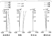
Fig. 2 A, Fig. 2 B, Fig. 2 C and Fig. 2 D be according to first embodiment of the invention respectively at the wide-angle side place, the aberration diagram at zoom position place and telescope end place in the middle of the zoom position place, second in the middle of first.
Fig. 3 illustrates the lens cross section, and (A), (B), (C) and (D) represent respectively according to second embodiment of the invention respectively at the wide-angle side place, the state at zoom position place and telescope end place in the middle of the zoom position place, second in the middle of first.
Fig. 4 A, Fig. 4 B, Fig. 4 C and Fig. 4 D be according to second embodiment of the invention respectively at the wide-angle side place, the aberration diagram at zoom position place and telescope end place in the middle of the zoom position place, second in the middle of first.
Fig. 5 illustrates the lens cross section, and (A), (B), (C) and (D) represent respectively according to third embodiment of the invention respectively at the wide-angle side place, the state at zoom position place and telescope end place in the middle of the zoom position place, second in the middle of first.
Fig. 6 A, Fig. 6 B, Fig. 6 C and Fig. 6 D be according to third embodiment of the invention respectively at the wide-angle side place, the aberration diagram at zoom position place and telescope end place in the middle of the zoom position place, second in the middle of first.
Fig. 7 illustrates the lens cross section, and (A), (B), (C) and (D) represent respectively according to fourth embodiment of the invention respectively at the wide-angle side place, the state at zoom position place and telescope end place in the middle of the zoom position place, second in the middle of first.
Fig. 8 A, Fig. 8 B, Fig. 8 C and Fig. 8 D be according to fourth embodiment of the invention respectively at the wide-angle side place, the aberration diagram at zoom position place and telescope end place in the middle of the zoom position place, second in the middle of first.
Fig. 9 illustrates the lens cross section, and (A), (B), (C) and (D) represent respectively according to fifth embodiment of the invention respectively at the wide-angle side place, the state at zoom position place and telescope end place in the middle of the zoom position place, second in the middle of first.
Figure 10 A, Figure 10 B, Figure 10 C and Figure 10 D be according to fifth embodiment of the invention respectively at the wide-angle side place, the aberration diagram at zoom position place and telescope end place in the middle of the zoom position place, second in the middle of first.
Figure 11 illustrates the lens cross section, and (A), (B), (C) and (D) represent respectively according to sixth embodiment of the invention respectively at the wide-angle side place, the state at zoom position place and telescope end place in the middle of the zoom position place, second in the middle of first.
Figure 12 A, Figure 12 B, Figure 12 C and Figure 12 D be according to sixth embodiment of the invention respectively at the wide-angle side place, the aberration diagram at zoom position place and telescope end place in the middle of the zoom position place, second in the middle of first.
Figure 13 is the synoptic diagram of the major part when being illustrated in zoom lens of the present invention and being applied to digital camera.
Embodiment
To describe the preferred embodiments of the present invention in detail according to accompanying drawing now.
Hereinafter, describe according to zoom lens of the present invention with comprise image pick up equipment according to zoom lens of the present invention.At least comprise five lens units according to zoom lens of the present invention, its from object side to be followed successively by first lens unit with positive refracting power, second lens unit with negative refracting power, aperture diaphragm as side, have the 3rd lens unit of positive refracting power, the 5th lens unit that has the 4th lens unit of negative refracting power and have positive refracting power.Also exist and wherein will have the situation of the 6th lenticular element arrangement of positive refracting power or negative refracting power in the picture side of the 5th lens unit.During zoom, move first lens unit and second lens unit at least.
Specifically; During the zoom from the wide-angle side to the telescope end; First lens unit moves along the track towards image planes side protrusion, makes to compare with wide-angle side that the interval of far-end between first lens unit and second lens unit that be visible increases and interval between second lens unit and the 3rd lens unit reduces.In addition, second lens unit is to the image planes side shifting.Aperture diaphragm moves and makes the interval of the 3rd lens unit change.If with the picture side of the 6th lenticular element arrangement, then do not move the 6th lens unit, but can move the 6th lens unit where necessary for aberration correction for zoom at the 5th lens unit.
(A)-(D) among Fig. 1 illustrates the lens cross section of locating according to zoom position place and telescope end (long focal length extremity) in the middle of the zoom position place, second in the middle of the locating in wide-angle side (short focal length extremity) respectively of the zoom lens of first embodiment of the invention, first.Fig. 2 A, Fig. 2 B, Fig. 2 C and Fig. 2 D be according to the zoom lens of first embodiment respectively at the wide-angle side place, the aberration diagram at zoom position place and telescope end place in the middle of the zoom position place, second in the middle of first.(A) among Fig. 3, (B), (C) and (D) illustrate according to the zoom lens of second embodiment of the invention respectively at the wide-angle side place, in the middle of the zoom position place, second the lens cross section at zoom position place and telescope end place in the middle of first.Fig. 4 A, Fig. 4 B, Fig. 4 C and Fig. 4 D be according to the zoom lens of second embodiment respectively at the wide-angle side place, the aberration diagram at zoom position place and telescope end place in the middle of the zoom position place, second in the middle of first.(A)-(D) among Fig. 5 illustrate according to the zoom lens of third embodiment of the invention respectively at the wide-angle side place, in the middle of the zoom position place, second the lens cross section at zoom position place and telescope end place in the middle of first.
Fig. 6 A, Fig. 6 B, Fig. 6 C and Fig. 6 D be according to the zoom lens of the 3rd embodiment respectively at the wide-angle side place, the aberration diagram at zoom position place and telescope end place in the middle of the zoom position place, second in the middle of first.(A)-(D) among Fig. 7 illustrate according to the zoom lens of fourth embodiment of the invention respectively at the wide-angle side place, in the middle of the zoom position place, second the lens cross section at zoom position place and telescope end place in the middle of first.Fig. 8 A, Fig. 8 B, Fig. 8 C and Fig. 8 D be according to the zoom lens of the 4th embodiment respectively at the wide-angle side place, the aberration diagram at zoom position place and telescope end place in the middle of the zoom position place, second in the middle of first.(A)-(D) among Fig. 9 illustrate according to the zoom lens of fifth embodiment of the invention respectively at the wide-angle side place, in the middle of the zoom position place, second the lens cross section at zoom position place and telescope end place in the middle of first.Figure 10 A, Figure 10 B, Figure 10 C and Figure 10 D be according to the zoom lens of the 5th embodiment respectively at the wide-angle side place, the aberration diagram at zoom position place and telescope end place in the middle of the zoom position place, second in the middle of first.(A)-(D) among Figure 11 illustrate according to the zoom lens of sixth embodiment of the invention respectively at the wide-angle side place, in the middle of the zoom position place, second the lens cross section at zoom position place and telescope end place in the middle of first.Figure 12 A, Figure 12 B, Figure 12 C and Figure 12 D be according to the zoom lens of the 6th embodiment respectively at the wide-angle side place, the aberration diagram at zoom position place and telescope end place in the middle of the zoom position place, second in the middle of first.
Figure 13 is the synoptic diagram that the major part of the camera (image pick up equipment) that comprises zoom lens of the present invention is shown.The zoom lens of each embodiment are the capture lens systems that are used for image pick up equipment (for example video camera, digital camera and silver halide film camera).In the lens cross section, the left side is corresponding to object side (object side) (front side), and the right side is corresponding to picture side (rear side).In the lens cross section, the order of the lens unit that i representes to begin from object side, and Li representes i lens unit.
In the lens cross section of first embodiment that in Fig. 1, Fig. 5, Fig. 7 and Fig. 9, illustrates respectively, the 3rd embodiment, the 4th embodiment and the 5th embodiment, zoom lens comprise the first lens unit L1, the second lens unit L2 with negative refracting power, the 3rd lens unit L3 with positive refracting power with positive refracting power, have the 4th lens unit L4 of negative refracting power and have the 5th lens unit L5 of positive refracting power.Each embodiment among those embodiment describes the five unit zoom lens that just guide (positive-lead) type.
In the lens cross section of second embodiment shown in Fig. 3, zoom lens comprise the first lens unit L1, the second lens unit L2 with negative refracting power, the 3rd lens unit L3 with positive refracting power, the 4th lens unit L4 with negative refracting power with positive refracting power, have the 5th lens unit L5 of positive refracting power and have the 6th lens unit L6 of positive refracting power.Second embodiment describes the six unit zoom lens that just guiding type.In the lens cross section of the 6th embodiment shown in Figure 11, zoom lens comprise the first lens unit L1, the second lens unit L2 with negative refracting power, the 3rd lens unit L3 with positive refracting power, the 4th lens unit L4 with negative refracting power with positive refracting power, have the 5th lens unit L5 of positive refracting power and have the 6th lens unit L6 of negative refracting power.The 6th embodiment describes the six unit zoom lens that just guiding type.
In each embodiment, aperture diaphragm SP is disposed in the object side of the 3rd lens unit L3.Optical block G is corresponding to light filter, panel (face plate), crystal low-pass filter, infrared cutoff filter etc.When zoom lens are used as the photographic optical system of video camera or digital still camera, arrange that the photosensitive surface corresponding with the imaging plane of solid-state image pickup device (OE converter element) (for example charge-coupled device (CCD) sensor or complementary metal oxide semiconductor (CMOS) (CMOS) sensor) is as image planes IP.Alternately,, arrange by zoom lens when being used for the silver halide film camera and the corresponding photosensitive surface in film surface.In aberration diagram, d, g, C and F represent d line, g line, C line and F line respectively.Δ M and Δ S represent meridianal image surface and sagittal image surface respectively.Lateral chromatic aberration is represented by g line, C line and F line.Symbol " w " is represented half-court angle (becoming the half value of the angle of image field), and Fno representes the F number.In addition, in each embodiment that is described below, wide-angle side and telescope end refer to the zoom position when the lens unit that is used for zoom is positioned at each the end place along the mechanical mobile range of optical axis.In each embodiment, arrow is pointed out during the zoom from the wide-angle side to the telescope end or the motion track during focusing on.
In each embodiment, during zoom, move the first lens unit L1 and the second lens unit L2 at least.In this case, compare the interval of far-end between the first lens unit L1 and the second lens unit L2 that be visible with wide-angle side and increase, make the zoom ratio of the second lens unit L2 increase.Interval between the second lens unit L2 and the 3rd lens unit L3 reduces, and makes the 3rd lens unit L3 have to be used to reduce the Zoom effect of variation of the spherical aberration that caused by zoom and filed curvature.Specifically, during the zoom from the wide-angle side to the telescope end the first lens unit L1 along moving towards track as side protrusion as arrow is shown.
Zoom position when here, the first lens unit L1 is positioned at during the zoom the position near the image planes side is a zoom position in the middle of first.Be illustrated respectively in the focal length of the wide-angle side place and the far-end total system of being visible by fw and ft.In this case, when representing the focal length of total system by fm2, the zoom position that satisfies the focal distance f m2 of following formula is the second middle zoom position.
fm2=(fw.ft)
1/2...(A)
Compare the far-end second lens unit L2 that is visible to the image planes side shifting with the wide-angle side place.Aperture diaphragm SP moves along the track different with the track of the 3rd lens unit L3.The 3rd lens unit L3 moves or does not move to object side.The 4th lens unit L4 moves to object side or to the image planes side monotonously, does not perhaps move.
The 5th lens unit L5 moves with non-directional mode, changes thereby proofread and correct the image planes that caused by zoom.In addition, adopt back focusing type, on optical axis, move the 5th lens unit L5 therein to be used for focusing.Be visible far-end from the object of unlimited distance to the focusing of the object of close, shown in the arrow 5c in each lens cross section, with the 5th lens unit L5 band to the front side.Block curve 5a relevant with the 5th lens unit L5 and dashed curve 5b represent to be used to proofread and correct the motion track of the image planes variation that when the object of object that focuses on unlimited distance or close, is caused by the zoom from the wide-angle side to the telescope end respectively.Note that and to carry out focusing through moving the 4th lens unit L4.
In second embodiment shown in Fig. 3 and Figure 11 and the 6th embodiment, do not move the 6th lens unit L6 for zoom.In order to obtain the high zoom ratios in the five unit zoom lens, be more preferably setting and have second lens unit L2 of big zoom effect and the big amount of movement during zoom of the 3rd lens unit L3.Yet, utilizing this method, the interval that is between the second lens unit L2 and the 3rd lens unit L3 in wide-angle side increases.Therefore,, then increase, and the lens that therefore constitute the first lens unit L1 become big at the interval that wide-angle side is between front lens (the first lens unit L1) and the aperture diaphragm SP if aperture diaphragm SP and the 3rd lens unit L3 are integral.For fear of this, move aperture diaphragm SP independently with other lens unit, make that comparing the interval of far-end between aperture diaphragm SP and the 3rd lens unit L3 that be visible with the wide-angle side place diminishes.Because aperture diaphragm SP is arranged to and has than the 3rd lens unit L3 more near the interval of object side the scope from wide-angle side to middle zooming range; Therefore with near aperture diaphragm SP being arranged in the 3rd lens unit L3 make the situation that they move integratedly compare, the entrance pupil distance reduces.Therefore, can reduce through the first lens unit L1 and the second lens unit L2 from the height of incidence of Axial Bundle.Therefore, can obtain to constitute thickness and the effect that effective diameter reduces of the lens of lens unit.In addition, if move aperture diaphragm SP integratedly with the 3rd lens unit L3, then scope from wide-angle side to middle zooming range in order to ensure light quantity enough on the periphery of screen, reduced sharp in the peripheral upper periphery light quantity of screen.
On the other hand, if scope, aperture diaphragm SP is moved suitable amount from the 3rd lens unit L3 to object side from wide-angle side to middle zooming range, then since axial pencil disperse and can reduce the aperture diaphragm diameter.Through reducing the aperture diaphragm diameter and, can clipping a part that arrives the low image height with the rink corner of periphery from Axial Bundle through aperture diaphragm SP is arranged in object side.Therefore therefore, the minimizing of the light quantity on the periphery of screen can be mild, and the minimizing of peripheral light amount is not remarkable.In addition, because aperture diaphragm is arranged to than the 3rd lens unit L3 more near object side in middle zooming range, therefore can clip flash of light (flare) component from Axial Bundle.Note that at each zoom position place aperture diaphragm diameter can be that fix or variable.Preferably the aperture diaphragm diameter is fixed, because the control of aperture diaphragm SP becomes easy.
On the other hand, the aperture diaphragm diameter can be variable, thereby the scope from middle zooming range to telescope end, reduces the aperture diaphragm diameter.According to this configuration, can scope, clip from the flash of light component of Axial Bundle and can reduce the height on the front lens of Axial Bundle process, and therefore can reduce the front lens effective diameter from middle zooming range to telescope end.In each embodiment, move aperture diaphragm SP as described above, thereby reduce the height of distance through the optical axis of the peripheral light beam of front lens at zoom position place near wide-angle side.As a result, confirm the front lens effective diameter by the height of incidence of zoom position place peripheral light beam in the middle of first.In order to realize further reducing of front lens effective diameter, preferably reduce the height of incidence of the light beam of zoom position place process front lens in the middle of first.Therefore, preferably the first lens unit L1 moves along the track towards image planes side protrusion during zoom, thereby the zoom position place is more near aperture diaphragm SP in the middle of first.Note that with the first lens unit L1 towards image planes move by side to zoom position in the middle of first and the far-end that is visible subsequently from first in the middle of the method that moves towards object side of zoom position can give the second lens unit L2 enough zoom ratios.Foregoing description is the condition of motion track that in each embodiment, is used to realize the aperture diaphragm during zoom and the lens unit of high zoom ratios and little front lens effective diameter.
Next, describe and to be arranged to than aperture diaphragm SP more near the negative refracting power of the 4th lens unit L4 of image planes side.Because having the lens unit of negative refracting power is arranged to than aperture diaphragm SP more near the image planes side; Therefore compare with the zoom lens of four cellular constructions that comprise positive lens, negative lens, positive lens and positive lens; The front lens effective diameter can reduce, and this is for realizing that the angle, square is favourable.Reason is described as follows.Between with respect to the object side of aperture diaphragm SP and image planes side, has light beam height from Axial Bundle with respect to the optical axis counter-rotating.From Axial Bundle through being arranged to than aperture diaphragm SP more near the image planes side have the lens unit of negative refracting power the time receive the influence of disperse function, but the aperture diaphragm SP that is inverted than its place's light beam height of incidence is more near the influence that Axial Bundle receives converging action of leaving of object side.Therefore, the 4th lens unit L4 that has negative refracting power therein is arranged to than aperture diaphragm SP more can further reduce the height of incidence from Axial Bundle through front lens near the structure of image planes side.In addition, because the 4th lens unit L4 can share zoom ratio, therefore compare with the zoom lens of four cellular constructions that comprise positive lens, negative lens, positive lens and positive lens, this structure is favourable for the high zoom ratios that realizes zoom lens also.In each embodiment; As stated; Be arranged on the motion track of the first lens unit L1 and aperture diaphragm SP during the zoom; And suitably be provided with and be arranged to than aperture diaphragm SP, thereby realize reducing of high zoom ratios and front lens effective diameter more near the negative refracting power of the 4th lens unit L4 of image planes side.
In each embodiment, the focal length of the 4th lens unit L4 represented by f4, and the be visible focal length of far-end of total system is represented by ft.Represent by m1 with respect to the wide-angle side amount of movement of the far-end first lens unit L1 on optical axis direction that be visible, and the zoom position when being positioned at the position near the image planes side from wide-angle side to the first lens unit L1, the amount of movement of the first lens unit L1 on optical axis direction represented by m1mid.Thereby expression formula meets the following conditions.
0.10<|f4/ft|<0.45 ...(1)
0.03<m1mid/|m1|<0.70 ...(2)
Amount of movement m1 is the first lens unit L1 poor between the position of the position at wide-angle side place and the far-end that is visible, and amount of movement m1mid is the first lens unit L1 the position at wide-angle side place and poor between the position at zoom position place in the middle of first.In addition, if the position at lens unit each place in the zoom position in the middle of telescope end and first with compare in the position at wide-angle side place more near the image planes side, then the symbol of amount of movement is set as positive.
The technical meaning of conditional expression (1) and (2) next, is described.Conditional expression (1) limits the refracting power of the 4th lens unit L4.If the refracting power of the 4th lens unit L4 becomes too little so that surpasses the higher limit of conditional expression (1), the disperse function from Axial Bundle that then is applied to the image planes side of aperture diaphragm SP becomes too little.As a result, big through the height of incidence change from Axial Bundle of front lens (the first lens unit L1), and therefore become difficult to achieve reducing of front lens effective diameter.In addition, sharing of the zoom of the 4th lens unit L4 becomes too little, and therefore becomes difficult to achieve high zoom ratios.If the refracting power of the 4th lens unit L4 becomes too big so that is lower than the lower limit of conditional expression (1); The disperse function that then is applied to from the 4th lens unit L4 of Axial Bundle becomes too big; And the filed curvature or the lateral chromatic aberration that produce become too big, and therefore become and be difficult to proofread and correct filed curvature or the lateral chromatic aberration that is produced by other lens unit.
Conditional expression (2) limits the motion track of the first lens unit L1 that follows zoom.The first lens unit L1 moves along the track towards image planes side protrusion, and therefore near the scope zoom position in the middle of wide-angle side to the first the entrance pupil distance reduce.Therefore, realize little front lens effective diameter.If the amount of movement at first lens unit L1 zoom position place in the middle of first becomes too big so that surpasses the higher limit of conditional expression (2); Then as the flex point of motion track first in the middle of near the zoom position the variation of filed curvature become too big, and therefore become and be difficult to proofread and correct this flex point by other lens unit.On the contrary; If the first lens unit L1 becomes too little so that is lower than the lower limit of conditional expression (2) to the amount of movement of image planes side; Then the height of incidence from Axial Bundle through front lens increases near zoom position in the middle of first, and therefore the front lens effective diameter increases inadequately.The numerical range of conditional expression (1) and (2) more preferably is set as follows.
0.12<|f4/ft|<0.42 ...(1a)
0.08<m1mid/|m1|<0.65 ...(2a)
In addition, conditional expression (1a) and numerical range (2a) more preferably are set.
0.13<|f4/ft|<0.40 ...(1b)
0.12<m1mid/|m1|<0.60 ...(2b)
Utilize said structure, can obtain to have little front lens effective diameter, angle, square, high zoom ratios and the zoom lens of on whole zooming range, fully proofreading and correct the high optical property of the various aberrations that comprise aberration on the axle, lateral chromatic aberration, spherical aberration and filed curvature.
In each embodiment, one or more in more preferably meeting the following conditions.By dspw and dspt be illustrated respectively in the wide-angle side place and be visible far-end aperture diaphragm SP and the 3rd lens unit L3 near the interval between the lens surface of object side.By d23w be illustrated in wide-angle side be in the second lens unit L2 near the lens surface of image planes side and the 3rd lens unit L3 near the interval between the lens surface of object side.The focal length of the first lens unit L1, the second lens unit L2 and the 5th lens unit L5 is represented by f1, f2 and f5 respectively.Total system is represented by fw at the focal length at wide-angle side place.The first lens unit L1 comprises one or more positive lens.Among positive lens, be arranged near the refractive index about the d line of the material of the positive lens of object side and represent, and the Abbe number of this material is represented by vd1p by nd1p.
The second lens unit L2 is represented by β 2w and β 2t respectively with the lateral magnification of the far-end that is visible at the lateral magnification at wide-angle side place.The 3rd lens unit L3 is represented by β 3w and β 3t respectively with the lateral magnification of the far-end that is visible at the lateral magnification at wide-angle side place.The amount of movement on optical axis direction from the wide-angle side to the telescope end of the second lens unit L2 is represented by m2.Represent by BFw and BFt respectively in the back focal length (back focus) at wide-angle side place and the back focal length of the far-end that is visible.In this case, preferably meet the following conditions in the expression formula one or more.
0.05<(dspw-dspt)/d23w<0.40 ...(3)
8.0<f1/fw<30.0...(4)
vd1p>65.0...(5)
nd1p>-0.0050·vd1p+1.885...(6)
1.5<(β2t/β2w)/(β3t/β3w)<5.0...(7)
-12.0<f1/t2<-4.0...(8)
2.0<f5/fw<15.0...(9)
10<(β2t·β3t)/(β2w·β3w)<40...(10)
-3.5<m1/m2<0.0...(11)
0.7<BFt/BFw<1.3...(12)
Note that back focal length is defined in the air scaled value of the distance between last surface of lens and the paraxonic imaging surface (air-converted value).In addition, amount of movement m2 is the second lens unit L2 poor between the position of the position at wide-angle side place and the far-end that is visible.In addition, when the far-end lens that are visible with respect to wide-angle side during more near the image planes side, the symbol of amount of movement m2 is considered to positive.
Next, the technical meaning of above-mentioned conditional expression is described.What conditional expression (3) limited aperture diaphragm SP follows moving of zoom.If the interval between aperture diaphragm SP of wide-angle side place and the 3rd lens unit L3 becomes too big so that surpasses the higher limit of conditional expression (3), then the wide-angle side place through the axle of the 3rd lens unit L3 on the height of incidence of light beam become too big.As a result, the effective diameter that constitutes the lens of the 3rd lens unit L3 becomes too big inadequately.In addition, the center thickness that constitutes the positive lens of the 3rd lens unit L3 increases, and the thickness increase of whole the 3rd lens unit L3 on optical axis direction, and therefore total length of lens increases.On the contrary; If be in the lower limit that interval between aperture diaphragm SP and the 3rd lens unit L3 becomes too little so that is lower than conditional expression (3) in wide-angle side; Then the entrance pupil distance becomes too big the scope from wide-angle side to middle zooming range, and therefore the front lens effective diameter increases.
Conditional expression (4) limits the refracting power of the first lens unit L1.If the refracting power of the first lens unit L1 becomes too little so that surpasses the higher limit of conditional expression (4); Then in order to realize having the angle, square at about 35 degree or bigger imaging half-court angle at the wide-angle side place, the refracting power of the 3rd lens unit L3 and the 4th lens unit L4 becomes too big.As a result, become to be difficult to proofread and correct fully and change and flash of light at the imaging surface on the screen periphery during the zoom.In addition, the amount of movement of the first lens unit L1 increases during zoom, and therefore total length of lens and the increase of front lens effective diameter.On the contrary; If the refracting power of the first lens unit L1 becomes too big so that is lower than the lower limit of conditional expression (4); Then the bigger wide-angle side place of height of incidence from Axial Bundle on the first lens unit L1 produces a lot of lateral chromatic aberrations therein, and therefore becomes and be difficult to proofread and correct lateral chromatic aberration by other lens unit.
Conditional expression (5) and (6) limit be included among the first lens unit L1 and be arranged to material near the positive lens G1p of object side.If the Abbe number vd1p of the material of positive lens G1p becomes too little so that is lower than the value on the right side of conditional expression (5), then becoming is difficult to proofread and correct the second order spectrum that in the first lens unit L1, produces.Especially, be visible that the second order spectrum of aberration and lateral chromatic aberration increases on the far-end axle.As a result, the color stain (color stain) that the quilt of the captured image of far-end that particularly is visible is taken the photograph on the profile of body increases, and resolution reduces, and therefore becoming is difficult to obtain high optical property.In addition, if the refractive index of the material of positive lens G1p becomes too little so that is lower than the value that the right side conditional expression (6) limits, then the curvature of the lens surface of positive lens G1p becomes big (precipitous).Therefore therefore, produce a lot of spherical aberrations, and become and be difficult to by other lens correction spherical aberration.
Conditional expression (7) is limited to the ratio between the zoom ratio of zoom ratio and the 3rd lens unit L3 of the second lens unit L2.If the zoom ratio of the second lens unit L2 becomes too big so that surpasses the higher limit of conditional expression (7); Then follow the for example lateral chromatic aberration that zoom produces in the second lens unit L2 and the various aberrations of filed curvature to become too greatly, and therefore become and be difficult to change by other lens correction aberration.On the contrary; If the zoom ratio of the 3rd lens unit L3 becomes too big so that is lower than the lower limit of conditional expression (7); Then follow the spherical aberration that in the 3rd lens unit L3, produces of zoom to become too big, therefore becoming is difficult to by other lens unit correcting spherical aberration.
Conditional expression (8) is limited to the ratio between the refracting power of refracting power and the second lens unit L2 of the first lens unit L1.If the refracting power of the second lens unit L2 becomes too little so that surpasses the higher limit of conditional expression (8), then being used to guarantee is the amount of movement increase of the required zoom ratio of the second lens unit L2, and therefore total length of lens and the increase of front lens effective diameter.On the contrary; If the refracting power of the second lens unit L2 becomes too big so that is lower than the lower limit of conditional expression (8); Then produce a lot of lateral chromatic aberrations or filed curvature by the second lens unit L2; Therefore and it is too big that the variation of following zoom becomes, and become and be difficult to by other lens unit it proofreaied and correct.
Conditional expression (9) limits the refracting power of the 5th lens unit L5.If the refracting power of the 5th lens unit L5 becomes too little so that surpasses the higher limit of conditional expression (9), the calibration capability that then is used to follow the image planes of zoom to change at the zoom position place near telescope end becomes not enough.As a result, the amount of movement of the 5th lens unit L5 during zoom becomes and makes total length of lens increase too greatly.In addition, at the zoom position place near telescope end, the 5th lens unit L5 follows the amount of movement of focusing to become too big so that can not be set to the distance of the object of close.On the other hand; If the refracting power of the 5th lens unit L5 becomes too big so that is lower than the lower limit of conditional expression (9); The variation of then following the for example axle of focusing to go up the aberration of aberration, lateral chromatic aberration and filed curvature becomes too big, and therefore worsens in the optical property of the object of close.
Conditional expression (10) limits the zoom ratio of the second lens unit L2 and the 3rd lens unit L3.If the zoom ratio of the second lens unit L2 and the 3rd lens unit L3 becomes too big so that surpasses the higher limit of conditional expression (10); Therefore then follow the variation of lateral chromatic aberration, spherical aberration and the filed curvature of zoom to become too big, and become and be difficult to proofread and correct this variation by other lens unit.If the zoom ratio of the second lens unit L2 and the 3rd lens unit L3 becomes too little so that is lower than the lower limit of conditional expression (10), then becoming is difficult to obtain high zoom ratios.
Conditional expression (11) limits the first lens unit L1 and the amount of movement of the second lens unit L2 during zoom.If compare be visible the far-end first lens unit L1 and the second lens unit L2 moved so that surpassed higher limit from conditional expression (11) to unidirectional position with the wide-angle side place; Then becoming is difficult to obtain enough zoom ratios by the second lens unit L2, and therefore becomes and be difficult to obtain high zoom ratios.In addition; On the contrary; If the amount of movement of the first lens unit L1 becomes too big so that is lower than the lower limit of conditional expression (11); Then total length of lens increases, and is increasing through the height of incidence from Axial Bundle of the first lens unit L1 near the zoom position place of telescope end, and therefore the front lens effective diameter increases.
Conditional expression (12) is limited to the ratio between the back focal length of the back focal length at wide-angle side place and the far-end that is visible.The far-end back focal length becomes oversize so that surpasses the higher limit of conditional expression (12) if be visible, and total length of lens of the far-end that then is visible increases.The far-end back focal length becomes too short so that is lower than the lower limit of conditional expression (12) if be visible, and then becomes to be difficult to absorb the variation of the back focal length that the foozle by lens causes, and therefore becomes and be difficult to guarantee the focusing to the infinite distance object.Note that the numerical range that preferably is provided with as follows in conditional expression (3)-(5) and (7)-(12).
0.07<(dspw-dspt)/d23w<0.35...(3a)
9.0<f1/fw<25.0...(4a)
vd1p>66.5...(5a)
1.8<(β2t/β2w)/(β3t/β3w)<4.0...(7a)
-10.0<f1/t2<-5.0...(8a)
2.5<f5/fw<13.0...(9a)
12<(β2t·β3t)/(β2w·β3w)<33...(10a)
-3.0<m1/m2<-0.2...(11a)
0.8<BFt/BFw<1.2...(12a)
In addition, more preferably be provided with as follows conditional expression (3a)-(5a) with (7a)-(12a) in numerical range so that make the maximum effect that obtains by each conditional expression.
0.08<(dspw-dspt)/d23w<0.30...(3b)
10.0<f1/fw<22.0...(4b)
vd1p>68.0...(5b)
2.0<(β2t/β2w)/(β3t/β3w)<3.2...(7b)
-9.0<f1/f2<-6.0...(8b)
3.0<f5/fw<12.0...(9b)
15<(β2t·β3t)/(β2w·β3w)<28...(10b)
-2.5<m1/m2<-0.3...(11b)
0.90<BFt/BFw<1.15...(12b)
In each embodiment, preferably constitute the 4th lens unit L4 by a lens subassembly.
This lens subassembly helps to reduce total length of lens, and can reduce the weight of the 4th lens unit L4, and this is for being favourable in the zoom drive.A lens subassembly can or comprise that the balsaming lens of one or more positive lens and negative lens constitutes by simple lens.Balsaming lens can help when realizing the angle, square of zoom lens, suitably to proofread and correct the lateral chromatic aberration at the wide-angle side place.Compare with the amount of movement of the 3rd lens unit L3 with the second lens unit L2, the amount of movement of the 4th lens unit L4 during zoom is little, thereby but sharing zoom ratio helps to realize high zoom ratios.Preferably constitute the 5th lens unit L5 by a lens subassembly.Moving the 5th lens unit L5 proofreaies and correct with the imaging surface that is used to follow zoom and is used for focusing on.Therefore, amount of movement is bigger, and its frequency is higher.For this reason, preferably constitute the 5th lens unit L5, thereby realize being used to reduce the light weight of driving moment by a lens subassembly.
In each embodiment, utilize said structure, realize 32 degree or the bigger imaging half-court angle and 20 or bigger zoom ratio at wide-angle side place.Note that a part and the 4th lens unit L4 that can move whole the 3rd lens unit L3 or the 3rd lens unit L3 make to have the component on the direction vertical with optical axis, are used to proofread and correct the fuzzy of captured image.The opening diameter of aperture diaphragm SP can be constant or variable during zoom.If the opening diameter of aperture diaphragm SP is constant, then the control of aperture diaphragm diameter can be simplified.On the other hand,, then be controlled as at the zoom position place hour, improve optical characteristics thereby can clip unnecessary light at the opening diameter of aperture diaphragm SP if bigger in any zoom position place's spherical aberration or flash of light.As stated, according to each embodiment, can obtain to have little front lens effective diameter, the zoom lens of little total length of lens, angle, square and high zoom ratios.Next, the lens arrangement of each embodiment is described.
First embodiment
Hereinafter, with reference to (A)-(D) among the figure 1, the zoom lens of the first embodiment of the present invention are described.The zoom lens of first embodiment from object side to comprising successively as side: have the first lens unit L1 of positive refracting power, the second lens unit L2 with negative refracting power, diaphragm (aperture diaphragm) SP, have positive refracting power the 3rd lens unit L3, have the 4th lens unit L4 of negative refracting power and have the 5th lens unit L5 of positive refracting power.In first embodiment, move each lens unit to be used for zoom.In this case, and compare at the wide-angle side place, the interval of far-end between the first lens unit L1 and the second lens unit L2 that be visible becomes bigger, so that increase the zoom ratio of the second lens unit L2.Then, move each lens unit, make that the interval between the second lens unit L2 and the 3rd lens unit L3 reduces.Therefore therefore, the 3rd lens unit L3 has Zoom effect, and can suppress to follow the variation of the filed curvature and the spherical aberration of zoom effectively.
Balsaming lens and the positive lens G13 that has the meniscus shape of nonreentrant surface at object side of negative lens G11 that the first lens unit L1 has positive lens G12 by gummed and has the meniscus shape of nonreentrant surface at object side constitutes.The first lens unit L1 is made up of three lens, and therefore acquisition high zoom ratios in the aberration of aberration and lateral chromatic aberration on can suitably proofreading and correct for example spherical aberration, axle.The second lens unit L2 is made up of three lens; Its from object side to be included in successively as side object side have the meniscus shape of nonreentrant surface negative lens, have towards the negative lens on the recessed surface of image planes side and have positive lens, so that suppress to follow the various aberrations of zoom to change thus towards the nonreentrant surface of object side.The 3rd lens unit L3 is by having towards the positive lens of the nonreentrant surface of object side, having towards the negative lens on the recessed surface of image planes side and the positive lens that has towards the nonreentrant surface of image planes side and constitute.Utilize this configuration of the 3rd lens unit L3, the object side principal point of the 3rd lens unit L3 can be disposed among the 3rd lens unit L3 near near the lens surface of object side, this is favourable for reducing the front lens diameter.In first embodiment, utilize above-mentioned configuration, realize the ω=imaging half-court angle of 37.9 degree at wide-angle side place and 26.8 zoom ratio.
Second embodiment
With reference to (A)-(D) among the figure 3, the zoom lens of the second embodiment of the present invention are described.These zoom lens from object side to comprising successively as side: have positive refracting power the first lens unit L1, have negative refracting power the second lens unit L2, have positive refracting power the 3rd lens unit L3, have negative refracting power the 4th lens unit L4, have the 5th lens unit L5 of positive refracting power and have the 6th lens unit L6 of positive refracting power.In a second embodiment, move the first lens unit L1 to the, five lens unit L5 to be used for zoom.In a second embodiment, realize the ω=half-court angle of 44.9 degree at wide-angle side place and about 30 zoom (zoom factor).Compare with first embodiment, added a lens unit becoming six cellular constructions, and therefore help higher aberration correction.Do not move the 6th lens unit L6, and the 6th lens unit L6 is arranged in the position near imaging surface for zoom.Just fixing the 6th lens unit L6 is enough in the place ahead of imaging device (solid-state image pickup device), and therefore can not make the zoom lens of realizing present embodiment under the lens barrel structure complicated situation like this of first embodiment.Owing to make the object side surface of the positive lens that constitutes the 6th lens unit L6 have aspherical shape, therefore suitably proofread and correct filed curvature.Thereby aspherical shape can be applied to obtaining identical effect as side surface.
In order to realize the angle, square and the high zoom ratios at wide-angle side place, through the incident angle of the peripheral light beam of the second lens unit L2 and height of incidence different widely between wide-angle side place and the telescope end place.Therefore, the filed curvature that in these lens units, produces that is caused by zoom and the variation (zoom variation) of lateral chromatic aberration cause problem.Therefore, the second lens unit L2 is made up of four lens, makes the zoom of the various aberrations follow zoom change to be suppressed for being little, and makes a surface of lens have aspherical shape.Therefore, especially, suitably proofread and correct the filed curvature on the direction (over direction) of crossing that produces at the wide-angle side place.Other lens arrangement of lens unit is basically the same as those in the first embodiment.
The 3rd embodiment
With reference to (A)-(D) among the figure 5, the zoom lens of the third embodiment of the present invention are described.Lens arrangement is five cellular constructions identical with first embodiment.Move the first lens unit L1 to the, five lens unit L5 to be used for zoom.For the ω=imaging half-court angle of 45.7 degree at realization wide-angle side place and about 30 zoom in the 3rd embodiment, the 4th lens unit L4 is made up of the balsaming lens that comprises positive lens and negative lens (lens subassembly).Therefore, suitably proofread and correct the variation of filed curvature and the lateral chromatic aberration of following zoom.In addition, in order to increase one-tenth objective angle of image field, must increase the refracting power of the second lens unit L2 at the wide-angle side place.Follow this, be in the big filed curvature that was created among the second lens unit L2 on the direction in wide-angle side.Therefore, make the surface that is positioned near the image planes side of the lens of the position of object side of the second lens unit L2 have aspherical shape, local radius-of-curvature increases (that is, focal power dies down) near lens surface therein.Therefore, proofread and correct filed curvature at the wide-angle side place, the feasible flatness that suitably keeps imaging surface.In addition, the lens that constitute the second lens unit L2 are processed by the glass material with high index of refraction.Therefore, suppress to cut down now and (Petzval sum) increase on negative direction by what the refracting power of following the second lens unit L2 that angle, square and high zoom ratios cause increased.Other lens arrangement of lens unit is basically the same as those in the first embodiment.
The 4th embodiment
With reference to (A)-(D) among the figure 7, the zoom lens of the fourth embodiment of the present invention are described.Lens arrangement is five cellular constructions identical with the 3rd embodiment.Move the first lens unit L1 to the, five lens unit L5 to be used for zoom.In the present embodiment, in order to realize the wider rink corner at wide-angle side place, the second lens unit L2 has aspheric four lens by each and constitutes, thus the appearance of the various aberrations of the for example lateral chromatic aberration at inhibition wide-angle side place and filed curvature.In the 4th embodiment, realize the ω=imaging half-court angle of 47.1 degree at wide-angle side place and about 30 zoom.Other lens arrangement of lens unit is identical with the 3rd embodiment's.
The 5th embodiment
With reference to (A)-(D) among the figure 9, the zoom lens of the fifth embodiment of the present invention are described.Lens arrangement is five cellular constructions identical with first embodiment.In the present embodiment, do not move the 3rd lens unit L3 for zoom.Therefore, the actuator that is used to drive the 3rd lens unit L3 becomes unnecessary, makes lens actuating device to be simplified, and this is favourable for reduction in power consumption with for noiseless driving.In the 5th embodiment, realize the ω=imaging half-court angle of 37.9 degree at wide-angle side place and about 20 zoom.
The 6th embodiment
With reference to (A)-(D) among Figure 11, the zoom lens of the sixth embodiment of the present invention are described.These zoom lens from object side to comprising successively as side: have positive refracting power the first lens unit L1, have negative refracting power the second lens unit L2, have positive refracting power the 3rd lens unit L3, have negative refracting power the 4th lens unit L4, have the 5th lens unit L5 of positive refracting power and have the 6th lens unit L6 of negative refracting power.Do not move the 4th lens unit L4 and the 6th lens unit L6 for zoom.Therefore, realize being used to driving the minimizing and the simplification of lens actuating device of quantity of the actuator of lens unit, and therefore compare with the situation of driving lens unit, present embodiment is favourable for reduction in power consumption with for noiseless driving.In addition, the 6th lens unit L6 is disposed in the position near imaging surface.Because the surface of the object side of the lens of formation the 6th lens unit L6 has aspherical shape, therefore suitably proofread and correct filed curvature.Thereby aspherical shape can be applied to obtaining identical effect as side surface.In the 6th embodiment, realize the ω=imaging half-court angle of 36.0 degree at wide-angle side place and about 20 zoom.
Described exemplary embodiment of the present invention above, but the invention is not restricted to those embodiment, it can be revised in the scope of spirit or changed variedly.Above-mentioned optical system in an embodiment is suitable for being used for the imaging len of camera.When camera was digital still camera or digital camera, camera comprised the solid-state image pickup device of the light of the image that reception is formed by imaging len.In each embodiment, near wide-angle side, produce the barrel distortion aberration widely, make the imaging scope of solid-state image pickup device be set to scope less than the imaging scope in other zoom position.The distortion of the image information that is obtained can be proofreaied and correct on electricity in the signal processing circuit of the view data of handling solid-state image pickup device, and therefore can export the image with distortion seldom.
Next, being described in reference to Figure 13 wherein will be according to the embodiment of zoom lens of the present invention as the digital still camera of photographic optical system.In Figure 13, digital still camera comprises camera body 20 and by any one photographic optical system that constitutes 21 in the top zoom lens of in first to the 6th embodiment, describing.Digital still camera also comprise be merged in the camera body, be used to receive the quilt that forms by photographic optical system 21 and take the photograph the solid-state image pickup device of the image of body (OE converter element) 22, for example ccd sensor or cmos sensor.Digital still camera also comprises storer 23, is used to write down and the corresponding information of image of by solid-state image pickup device 22 its quilt of carrying out opto-electronic conversion being taken the photograph body.Digital still camera also comprises the view finder 24 that is made up of display panels etc., is used to observe the image that the quilt that on solid-state image pickup device 22, forms is taken the photograph body.By this way, through zoom lens according to the present invention are used for image pick up equipment (for example digital still camera or video camera), the small-sized image pick up equipment with high optical property can be provided.In each embodiment, produce barrel distortion widely at the wide-angle side place, and therefore the imaging scope of solid-state image pickup device is set to less than the scope at other zoom position place.Can be by being used to handle the distortion of on electricity, proofreading and correct the image information that is obtained from the signal processing circuit of the signal of solid-state image pickup device, thus output has the image of distortion seldom.
Hereinafter, describe respectively and embodiments of the invention value corresponding embodiment.In each numerical value embodiment; The order of the optical surface that surface number i representes to begin from object side; Ri representes the radius-of-curvature of i optical surface; Di is illustrated in the distance between i surface and (i+1) individual surface, and ndi and vdi represent refractive index and the Abbe number of the material of i optics about the d line respectively.Back focal length (BF) is defined in the air scaled value of the distance between last surface of lens and the paraxonic imaging surface, and total length of lens is defined as through back focal length (BF) being added to the value that the distance between lens front surface and the last surface of lens obtains.The unit of length is mm.In addition, K representes eccentricity, and A4, A6, A8 and A10 represent asphericity coefficient, and is represented by x with respect to the displacement on optical axis direction of surface vertices in the position apart from the height H of optical axis.Thereby, express aspherical shape by following equality.
(equality 1)
Wherein R representes radius-of-curvature.In addition, for example, the statement of " e-Z " means " 10
-z".In addition, corresponding being illustrated in the table 1 between above-mentioned conditional expression and each numerical value embodiment.Symbol f representes focal length, and Fno representes the F number, and ω representes the half-court angle.The half-court angle is by the definite value of light beam track (trace).
Unit: mm
Surface data
Surface number (i) r d nd vd
1 121.799 1.60 1.80610 33.3
2 49.556 4.62 1.49700 81.5
3 -194.668 0.18
4 42.248 3.00 1.60311 60.6
5 133.383 (variable)
6 84.974 1.00 1.88300 40.8
7 8.369 4.26
8 -24.608 0.70 1.77250 49.6
9 58.741 0.22
10 18.926 2.07 1.94595 18.0
11 102.403 (variable)
12 (diaphragm) ∞ (variable)
13*10.353 2.801.5831359.4
14*-109.462 2.90
15 23.498 0.70 1.84666 23.9
16 9.540 0.66
17 18.598 1.97 1.48749 70.2
18-25.104 (variable)
19 782.644 0.70 1.48749 70.2
20 24.650 (variable)
21 17.657 1.65 1.48749 70.2
22-1178.697 (variable)
23 ∞ 0.80 1.51633 64.1
24 ∞ 0.50
Image planes ∞
The non-spherical surface data
The 13 surface
K=5.51145e-001 A4=-1.38948e-004 A6=-8.42963e-007 A8=-1.89369e-008
The 14 surface
K=-1.00023e+001 A4=4.54336e-005
Various data
Zoom ratio 26.79
Focal length 5.15 8.68 26.98 137.95
F several 2.87 3.56 4.75 5.76
Half-court angle 37.9 24.9 8.16 1.60
Picture altitude 3.49 3.88 3.88 3.88
Total length of lens 90.92 85.01 103.56 127.20
BF 10.18 12.52 20.94 10.73
d5 0.78 6.37 31.22 57.27
d11 31.79 22.02 10.64 2.46
d12 10.87 4.78 1.08 0.80
d18 2.59 4.26 6.26 8.71
d20 5.68 6.01 4.38 18.20
d22 9.15 11.50 19.92 9.70
The Zoom lens unit data
Unit first surface focal length
1 1 78.27
2 6 -10.23
3 13 18.01
4 19 -52.23
5 21 35.70
Numerical value embodiment 2
Surface data
Surface number (i) r d nd vd
1 85.200 1.60 1.80000 29.8
2 41.164 6.05 1.49700 81.5
3 1981.992 0.18
4 42.972 3.38 1.71300 53.9
5 163.523 (variable)
6 120.140 1.00 1.80400 46.6
7 8.988 3.38
8 21.988 0.80 1.85960 40.4
9* 11.1792.96
10 -121.625 0.70 1.81600 46.6
11 30.103 0.30
12 16.537 2.12 1.92286 18.9
13 73.840 (variable)
14 (diaphragm) ∞ (variable)
15*7.856 2.621.5831359.4
16*21.3403.07
17 17.051 0.70 1.80518 25.4
18 8.004 0.32
19 9.507 2.79 1.48749 70.2
20-9.954 (variable)
21 -7.647 0.70 1.77250 49.6
22-16.822 (variable)
23 28.147 1.70 1.48749 70.2
24-96.067 (variable)
25*68.3211.001.5533271.7
26 153.178 1.00
27 ∞ 0.80 1.51633 64.1
28 ∞ 0.50
Image planes ∞
The non-spherical surface data
The 9th surface
K=-8.45926e-001 A4=3.70989e-005 A6=-1.14391e-007
The 15 surface
K=7.23287e-002 A4=-1.12090e-004 A6=-1.00884e-006 A8=-3.88181e-008
The 16 surface
K=-1.00023e+001 A4=2.35114e-004
The 25 surface
K=-4.82923e+001 A4=-1.50317e-004 A6=2.85996e-006
Various data
Zoom ratio 29.86
Focal length 3.95 7.34 21.44 117.99
F several 2.77 3.34 4.34 5.76
Half-court angle 44.9 28.2 10.1 1.86
Picture altitude 3.49 3.88 3.88 3.88
Total length of lens 91.75 85.38 101.15 126.62
BF 2.03 2.03 2.03 2.03
d5 0.78 6.46 25.81 50.32
d13 30.98 16.87 5.76 1.57
d14 11.13 8.04 5.60 1.32
d20 1.90 1.91 1.93 1.96
d22 2.69 5.91 8.63 24.05
d24 6.88 8.79 16.03 10.00
The Zoom lens unit data
Unit first surface focal length
1 1 71.32
2 6 -8.80
3 15 12.65
4 21 -18.77
5 23 44.86
6 252 21.96
Surface data
Surface number (i) r d nd vd
1 79.548 1.40 2.00069 25.5
2 48.163 4.93 1.49700 81.5
3 46140.146 0.15
4 47.433 3.21 1.77250 49.6
5 153.622 (variable)
6 180.621 1.10 1.88300 40.8
7 9.363 4.17
8 77.921 1.00 1.85960 40.4
9* 10.8882.59
10 18.975 2.23 1.94595 18.0
11 105.900 (variable)
12 (diaphragm) ∞ (variable)
13*7.739 2.901.5831359.4
14*19.3493.62
15 16.658 0.70 1.80518 25.4
16 7.512 0.22
17 8.191 2.59 1.48749 70.2
18-9.227 (variable)
19 -7.147 0.55 1.77250 49.6
20 -22.848 1.00 1.48749 70.2
21-16.607 (variable)
22 29.150 1.70 1.48749 70.2
23-37.230 (variable)
24 ∞ 0.80 1.51633 64.1
25 ∞ 0.80
Image planes ∞
The non-spherical surface data
The 9th surface
K=-8.88155e-001 A4=-5.86626e-005 A6=-2.32149e-007 A8=-3.41828e-009
The 13 surface
K=-2.16367e-001 A4=-6.54315e-006 A6=2.96112e-007 A8=-2.57814e-008
The 14 surface
K=-1.00023e+001 A4=3.61034e-004
Various data
Zoom ratio 29.87
Focal length 3.85 7.40 21.131 14.99
F several 2.87 3.78 4.65 5.76
Half-court angle 45.7 28.4 10.3 1.93
Picture altitude 3.49 3.88 3.88 3.88
Total length of lens 90.07 80.37 101.14 126.73
BF 9.13 10.88 16.70 9.94
d5 0.78 4.47 26.76 53.64
d11 37.08 21.57 7.65 1.59
d12 5.42 1.25 2.59 1.34
d18 1.95 2.03 2.03 2.06
d21 1.63 6.10 11.34 24.09
d23 7.81 9.55 15.37 8.61
The Zoom lens unit data
Unit first surface focal length
1 1 74.39
2 6 -9.18
3 13 12.39
4 19 -15.88
5 22 33.82
Numerical value embodiment 4
Surface data
Surface number (i) r d nd vd
1 88.341 1.40 2.00069 25.5
2 51.711 4.76 1.49700 81.5
3 -533.545 0.15
4 47.021 3.21 1.77250 49.6
5 134.387 (variable)
6 222.276 1.00 1.88300 40.8
7 9.418 3.74
8 33.065 1.00 1.85960 40.4
9*9.308 1.94
10 24.992 1.00 1.48749 70.2
11 18.144 0.84
12 16.663 2.28 1.92286 18.9
13 75.945 (variable)
14 (diaphragm) ∞ (variable)
15* 7.809 2.511.5533271.7
16* 33.9773.17
17 15.741 0.70 1.80518 25.4
18 8.129 0.42
19 11.872 2.28 1.48749 70.2
20-10.484 (variable)
21 -7.560 0.55 1.80400 46.6
22 78.309 1.25 1.48749 70.2
23-11.119 (variable)
24 27.138 1.70 1.48749 70.2
25-33.257 (variable)
26 ∞ 0.80 1.51633 64.1
27 ∞ 1.00
Image planes ∞
The non-spherical surface data
The 9th surface
K=-2.37707e+000 A4=1.61662e-004 A6=-1.57508e-006
The 15 surface
K=-3.51719e-001 A4=-9.49961e-006 A6=-4.43262e-007 A8=5.01439e-009
The 16 surface
K=-1.00023e+001 A4=1.75529e-004
Various data
Zoom ratio 29.56
Focal length 3.65 7.07 19.95 108.00
F several 2.87 3.70 4.56 5.76
Half-court angle 47.1 28.7 10.9 1.96
Picture altitude 3.49 3.88 3.88 3.70
Total length of lens 89.74 83.62 99.91 127.25
BF 8.51 9.88 16.60 9.33
d5 0.70 7.53 27.32 54.61
d13 34.882 1.32 7.34 1.60
d14 7.78 2.89 2.71 2.38
d20 2.61 2.72 2.72 2.79
d23 1.36 5.38 9.31 22.64
d25 6.98 8.35 15.08 7.81
The Zoom lens unit data
Unit first surface focal length
1 1 75.11
2 6 -8.94
3 15 12.48
4 21 -16.34
5 24 30.94
Numerical value embodiment 5
Surface data
Surface number (i) r d nd vd
1 88.862 1.30 1.90366 31.3
2 50.706 6.58 1.43387 95.1
3 -294.700 0.18
4 46.692 4.60 1.60311 60.6
5 201.469 (variable)
6 209.273 0.65 1.91082 35.3
7 8.482 3.68
8 -39.316 0.50 1.83481 42.7
9 24.823 0.56
10 20.991 1.97 2.00178 19.3
11*-276.414 (variable)
12 (diaphragm) ∞ (variable)
13*12.7222.151.5831359.4
14*-42.406 3.73
15 37.545 0.60 2.00069 25.5
16 11.693 0.30
17 14.132 1.91 1.51742 52.4
18 -16.875 0.30
19 ∞ (variable)
20 -165.497 0.55 1.59282 68.6
21 12.483 (variable)
22 14.630 3.28 1.69680 55.5
23 -20.789 0.50 1.94595 18.0
24-41.827 (variable)
25 ∞ 0.80 1.51633 64.1
26 ∞ 0.50
Image planes ∞
The non-spherical surface data
The 11 surface
K=-6.00511e+002 A4=-3.47482e-005 A6=-2.10099e-007
The 13 surface
K=2.30042e+000 A4=-1.82916e-004 A6=-2.13114e-006 A8=-1.06313e-008
A10=-1.07559e-009
The 14 surface
K=-1.00023e+001 A4=6.90199e-005 A6=-3.08796e-007
Various data
Zoom ratio 20.00
Focal length 5.15 8.13 23.07 103.00
F several 2.87 3.11 3.30 3.91
Half-court angle 37.9 26.3 9.49 2.15
Picture altitude 3.49 3.88 3.88 3.88
Total length of lens 105.66 98.67 111.64 122.17
BF 8.50 8.04 8.83 8.33
d5 0.78 8.42 36.61 59.17
d11 33.20 15.64 4.89 1.62
d12 11.86 14.79 10.33 1.57
d19 1.26 3.97 9.01 10.99
d21 16.73 14.48 8.65 7.17
d24 7.47 7.01 7.80 7.30
The Zoom lens unit data
Unit first surface focal length
1 1 80.90
2 6 -9.85
3 13 15.85
4 20 -19.56
5 22 17.52
Numerical value embodiment 6
Surface data
Surface number (i) r d nd vd
1 114.980 1.20 1.90366 31.3
2 42.641 0.15
3 43.124 3.37 1.59282 68.6
4 -192.018 0.16
5 35.490 2.61 1.60311 60.6
6 149.203 (variable)
7 213.504 0.75 1.88300 40.8
8 8.812 4.04
9 -21.897 0.65 1.71300 53.9
10 49.832 0.15
11 19.595 1.80 1.94595 18.0
12 154.459 (variable)
13 (diaphragm) ∞ (variable)
14* 11.364 2.981.5831359.4
15* -108.280 3.60
16 25.650 0.60 1.84666 23.9
17 10.138 0.49
18 15.249 2.07 1.48749 70.2
19 -27.912 0.30
20 ∞ (variable)
21 165.797 0.60 1.48749 70.2
22 17.437 (variable)
23 13.492 1.85 1.48749 70.2
24-193.547 (variable)
25* -75.8480.751.5533271.7
26 55.219 1.00
27 ∞ 0.80 1.51633 64.1
28 ∞ 0.50
Image planes ∞
The non-spherical surface data
The 14 surface
K=6.70000e-001 A4=-1.05133e-004 A6=-6.34101e-007 A8=-1.04927e-008
The 15 surface
K=-1.00023e+001 A4=5.28572e-005
The 25 surface
K=-1.10605e+004 A4=-3.01010e-004 A6=5.44350e-006
Various data
Zoom ratio 19.78
Focal length 5.50 9.80 24.50 108.80
F several 2.87 3.44 4.01 5.21
Half-court angle 36.0 22.4 9.03 2.02
Picture altitude 3.49 3.88 3.88 3.88
Total length of lens 91.76 83.93 94.18 106.11
BF 2.03 2.03 2.03 2.03
d6 0.70 5.50 22.50 41.00
d12 33.27 20.21 10.24 2.60
d13 9.90 5.86 3.58 1.35
d20 1.70 6.17 11.66 14.98
d22 8.77 8.18 4.96 11.18
d24 7.26 7.85 11.07 4.85
The Zoom lens unit data
Unit first surface focal length
1 1 60.31
2 7 -9.96
3 14 18.29
4 21 -40.03
5 23 25.95
6 25 -57.63
Table 1
Table 1

Though reference example property embodiment has described the present invention, should be appreciated that to the invention is not restricted to disclosed exemplary embodiment.Thereby the scope of following claim will be given the wideest explanation comprises all such modifications, equivalent configurations and function.
Claims (14)
1. zoom lens comprise to the image planes side from object side successively:
First lens unit with positive refracting power;
Second lens unit with negative refracting power;
Aperture diaphragm;
The 3rd lens unit with positive refracting power;
The 4th lens unit with negative refracting power; And
The 5th lens unit with positive refracting power, wherein:
During the zoom from the wide-angle side to the telescope end, first lens unit moves along the track towards image planes side protrusion, and second lens unit is towards the image planes side shifting, and aperture diaphragm moves;
The place compares with wide-angle side, the far-end that is visible, and the interval between first lens unit and second lens unit increases, and the interval between second lens unit and the 3rd lens unit reduces, and the interval between aperture diaphragm and the 3rd lens unit reduces; And
Expression formula meets the following conditions:
0.10 | f4/ft| < 0.45; And
0.03
<m1mid/>|m1|<0.70,
Wherein f4 representes the focal length of the 4th lens unit; Ft is illustrated in the focal length of telescope end place total system; M1 is illustrated in the amount of movement of first lens unit on optical axis direction during the zoom from the wide-angle side to the telescope end, and the zoom position of m1mid when representing to be positioned at the position near the image planes side from wide-angle side to first lens unit, the amount of movement of first lens unit on optical axis direction.
2. zoom lens according to claim 1, expression formula wherein meets the following conditions:
0.05<(dspw-dspt)/>d23w<0.40,
Wherein dspw and dspt represent separately: wide-angle side be in aperture diaphragm and the 3rd lens unit near the interval between the lens surface of object side; And be visible far-end aperture diaphragm and the 3rd lens unit near the interval between the lens surface of object side, and d23w be illustrated in wide-angle side be in second lens unit near the lens surface of image planes side and the 3rd lens unit near the interval between the lens surface of object side.
3. zoom lens according to claim 1, expression formula wherein meets the following conditions:
8.0
<f1/>fw<30.0,
Wherein f1 representes the focal length of first lens unit, and fw is illustrated in the focal length of wide-angle side place total system.
4. zoom lens according to claim 1, wherein:
First lens unit comprises one or more positive lens; And
Expression formula meets the following conditions:
ν d1p>65.0; With
nd1p>-0.0050·νd1p+1.885,
Wherein nd1p representes to be arranged to the refractive index about the d line near the material of the positive lens of object side, and ν d1p representes the Abbe number of said material.
5. zoom lens according to claim 1, expression formula wherein meets the following conditions:
1.5<(β2t/>β2w)/(β3t/β3w)<5.0,
Wherein β 2w and β 2t represent second lens unit respectively at the lateral magnification at the wide-angle side place lateral magnification with the far-end that is visible, and β 3w representes respectively that with β 3t the 3rd lens unit is at the lateral magnification at wide-angle side place and the lateral magnification of the far-end that is visible.
6. zoom lens according to claim 1, expression formula wherein meets the following conditions:
-12.0
<f1/>f2<-4.0,
Wherein f1 representes the focal length of first lens unit, and f2 representes the focal length of second lens unit.
7. zoom lens according to claim 1, expression formula wherein meets the following conditions:
2.0
<f5/>fw<15.0,
Wherein f5 representes the focal length of the 5th lens unit, and fw is illustrated in the focal length of wide-angle side place total system.
8. zoom lens according to claim 1, expression formula wherein meets the following conditions:
10<(β2t·β3t)/>(β2w·β3w)<40,
Wherein β 2w and β 2t represent second lens unit respectively at the lateral magnification at the wide-angle side place lateral magnification with the far-end that is visible, and β 3w representes respectively that with β 3t the 3rd lens unit is at the lateral magnification at wide-angle side place and the lateral magnification of the far-end that is visible.
9. zoom lens according to claim 1, expression formula wherein meets the following conditions:
-3.5
<m1/>m2<0.0,
Wherein m2 representes the amount of movement on optical axis direction from the wide-angle side to the telescope end of second lens unit.
10. zoom lens according to claim 1, expression formula wherein meets the following conditions:
0.7
<BFt/>BFw<1.3,
Wherein BFw and BFt are illustrated respectively in the back focal length at wide-angle side place and the back focal length of the far-end that is visible.
11. zoom lens according to claim 1, wherein the 4th lens unit is made up of a lens subassembly.
12. zoom lens according to claim 1, wherein the 5th lens unit is made up of a lens subassembly.
13. zoom lens according to claim 1, said zoom lens form image on solid-state image pickup device.
14. an image pick up equipment comprises:
According to any one described zoom lens in the claim 1 to 13; And
The solid-state image pickup device of the light image that reception is formed by zoom lens.
Applications Claiming Priority (2)
| Application Number | Priority Date | Filing Date | Title |
|---|---|---|---|
| JP2009-281431 | 2009-12-11 | ||
| JP2009281431A JP5489686B2 (en) | 2009-12-11 | 2009-12-11 | Zoom lens and imaging apparatus having the same |
Publications (2)
| Publication Number | Publication Date |
|---|---|
| CN102096179A CN102096179A (en) | 2011-06-15 |
| CN102096179B true CN102096179B (en) | 2012-11-14 |
Family
ID=44129342
Family Applications (1)
| Application Number | Title | Priority Date | Filing Date |
|---|---|---|---|
| CN2010105755989A Active CN102096179B (en) | 2009-12-11 | 2010-12-07 | Zoom lens and image pickup apparatus including the same |
Country Status (3)
| Country | Link |
|---|---|
| US (1) | US8184377B2 (en) |
| JP (1) | JP5489686B2 (en) |
| CN (1) | CN102096179B (en) |
Families Citing this family (20)
| Publication number | Priority date | Publication date | Assignee | Title |
|---|---|---|---|---|
| JP5624377B2 (en) * | 2009-07-23 | 2014-11-12 | 富士フイルム株式会社 | Zoom lens and imaging device |
| JP5720434B2 (en) * | 2011-06-23 | 2015-05-20 | 株式会社リコー | Imaging lens, camera device, and portable information terminal device |
| US8797655B2 (en) * | 2011-10-05 | 2014-08-05 | Canon Kabushiki Kaisha | Zoom lens and image pickup apparatus having the same |
| JP5436518B2 (en) * | 2011-10-21 | 2014-03-05 | キヤノン株式会社 | Zoom lens and imaging apparatus having the same |
| JP6004789B2 (en) * | 2012-07-03 | 2016-10-12 | キヤノン株式会社 | Zoom lens and imaging apparatus having the same |
| JPWO2014006653A1 (en) * | 2012-07-04 | 2016-06-02 | パナソニックIpマネジメント株式会社 | Zoom lens system, imaging device and camera |
| JP5798255B2 (en) | 2012-09-14 | 2015-10-21 | 富士フイルム株式会社 | Zoom lens and imaging device |
| JP2014145983A (en) | 2013-01-30 | 2014-08-14 | Olympus Imaging Corp | Zoom lens and imaging apparatus using the same |
| JP6212264B2 (en) * | 2013-02-05 | 2017-10-11 | オリンパス株式会社 | Zoom lens |
| JP6143501B2 (en) * | 2013-03-13 | 2017-06-07 | キヤノン株式会社 | Zoom lens and imaging apparatus having the same |
| JP5977888B2 (en) * | 2013-05-30 | 2016-08-24 | オリンパス株式会社 | Zoom lens and image pickup apparatus including the same |
| WO2015004703A1 (en) | 2013-07-12 | 2015-01-15 | パナソニックIpマネジメント株式会社 | Zoom lens system, imaging device, and camera |
| JP6261235B2 (en) * | 2013-08-28 | 2018-01-17 | キヤノン株式会社 | Zoom lens and imaging apparatus having the same |
| JP6223141B2 (en) * | 2013-11-18 | 2017-11-01 | キヤノン株式会社 | Zoom lens and imaging apparatus having the same |
| KR102094508B1 (en) | 2013-12-11 | 2020-03-27 | 삼성전자주식회사 | Zoom lens and photographing lens having the same |
| JP6880544B2 (en) * | 2015-09-30 | 2021-06-02 | 株式会社ニコン | Zoom lenses and optics |
| US10012822B2 (en) * | 2016-02-18 | 2018-07-03 | Panasonic Intellectual Property Management Co., Ltd. | Zoom lens system, interchangeable lens device and camera system with zoom lens system, and imaging apparatus with zoom lens system |
| JP7158849B2 (en) * | 2017-12-05 | 2022-10-24 | キヤノン株式会社 | ZOOM LENS AND IMAGING DEVICE HAVING THE SAME |
| JP2022063727A (en) * | 2020-10-12 | 2022-04-22 | キヤノン株式会社 | Zoom lens and image capturing device |
| JP2022088182A (en) * | 2020-12-02 | 2022-06-14 | キヤノン株式会社 | Zoom lens, lens device having the same, and image capturing device |
Citations (1)
| Publication number | Priority date | Publication date | Assignee | Title |
|---|---|---|---|---|
| CN101369049A (en) * | 2007-08-15 | 2009-02-18 | 索尼株式会社 | Zoom lens and image forming apparatus |
Family Cites Families (6)
| Publication number | Priority date | Publication date | Assignee | Title |
|---|---|---|---|---|
| US6124972A (en) | 1994-03-18 | 2000-09-26 | Canon Kabushiki Kaisha | Zoom lens having an image stabilizing function |
| JP4266617B2 (en) | 2001-12-28 | 2009-05-20 | オリンパス株式会社 | Wide-angle high-magnification zoom lens and photographing apparatus using the same |
| JP4794912B2 (en) * | 2005-06-02 | 2011-10-19 | キヤノン株式会社 | Zoom lens and imaging apparatus having the same |
| JP5111059B2 (en) * | 2007-11-05 | 2012-12-26 | キヤノン株式会社 | Zoom lens and imaging apparatus having the same |
| JP5294051B2 (en) * | 2008-03-25 | 2013-09-18 | 株式会社リコー | Zoom lens, imaging device |
| JP5541663B2 (en) * | 2009-10-06 | 2014-07-09 | キヤノン株式会社 | Zoom lens and imaging apparatus having the same |
-
2009
- 2009-12-11 JP JP2009281431A patent/JP5489686B2/en active Active
-
2010
- 2010-11-05 US US12/940,743 patent/US8184377B2/en active Active
- 2010-12-07 CN CN2010105755989A patent/CN102096179B/en active Active
Patent Citations (1)
| Publication number | Priority date | Publication date | Assignee | Title |
|---|---|---|---|---|
| CN101369049A (en) * | 2007-08-15 | 2009-02-18 | 索尼株式会社 | Zoom lens and image forming apparatus |
Non-Patent Citations (1)
| Title |
|---|
| JP特开2009-236973A 2009.10.15 |
Also Published As
| Publication number | Publication date |
|---|---|
| JP2011123337A (en) | 2011-06-23 |
| JP5489686B2 (en) | 2014-05-14 |
| US20110141577A1 (en) | 2011-06-16 |
| US8184377B2 (en) | 2012-05-22 |
| CN102096179A (en) | 2011-06-15 |
Similar Documents
| Publication | Publication Date | Title |
|---|---|---|
| CN102096179B (en) | Zoom lens and image pickup apparatus including the same | |
| CN102033304B (en) | Zoom lens system and image pickup apparatus including the same | |
| CN101587233B (en) | Zoom lens and image pickup apparatus including the same | |
| CN102216825B (en) | Zoom lens system and camera including the same | |
| JP6192338B2 (en) | Zoom lens and imaging apparatus having the same | |
| CN102109665B (en) | Zoom lens and image pickup apparatus including the same | |
| CN105739071A (en) | Zoom Lens And Image Pickup Apparatus Including The Same | |
| CN102243363A (en) | Zoom lens and imaging apparatus | |
| JP6004820B2 (en) | Zoom lens and image pickup apparatus having the same | |
| JP5959938B2 (en) | Zoom lens and imaging apparatus having the same | |
| JP2014202841A5 (en) | ||
| CN106468826B (en) | Zoom lens and image pick-up device comprising zoom lens | |
| JP2014021232A (en) | Zoom lens and image capturing device having the same | |
| CN103454758B (en) | Zoom lens and be equipped with the image pick up equipment of zoom lens | |
| CN107290844A (en) | Zoom lens and the image pick-up device using zoom lens | |
| JP2016048354A (en) | Zoom lens and imaging apparatus including the same | |
| JP6223141B2 (en) | Zoom lens and imaging apparatus having the same | |
| JP6579828B2 (en) | Zoom lens and imaging apparatus having the same | |
| CN102645733A (en) | Zoom lens and imaging apparatus | |
| JP6016500B2 (en) | Zoom lens and imaging apparatus having the same | |
| JP2017191126A (en) | Zoom lens and imaging device using the same | |
| CN102169223B (en) | Zoom lens and image pickup apparatus having the same | |
| JP6566747B2 (en) | Zoom lens and imaging apparatus having the same | |
| JP2010008679A (en) | Zoom lens and imaging apparatus | |
| JP5541749B2 (en) | Zoom lens and imaging apparatus having the same |
Legal Events
| Date | Code | Title | Description |
|---|---|---|---|
| C06 | Publication | ||
| PB01 | Publication | ||
| C10 | Entry into substantive examination | ||
| SE01 | Entry into force of request for substantive examination | ||
| C14 | Grant of patent or utility model | ||
| GR01 | Patent grant |