JP5111059B2 - Zoom lens and imaging apparatus having the same - Google Patents
Zoom lens and imaging apparatus having the same Download PDFInfo
- Publication number
- JP5111059B2 JP5111059B2 JP2007287273A JP2007287273A JP5111059B2 JP 5111059 B2 JP5111059 B2 JP 5111059B2 JP 2007287273 A JP2007287273 A JP 2007287273A JP 2007287273 A JP2007287273 A JP 2007287273A JP 5111059 B2 JP5111059 B2 JP 5111059B2
- Authority
- JP
- Japan
- Prior art keywords
- lens
- lens group
- zoom
- image
- wide
- Prior art date
- Legal status (The legal status is an assumption and is not a legal conclusion. Google has not performed a legal analysis and makes no representation as to the accuracy of the status listed.)
- Expired - Fee Related
Links
Images


Classifications
-
- G—PHYSICS
- G02—OPTICS
- G02B—OPTICAL ELEMENTS, SYSTEMS OR APPARATUS
- G02B15/00—Optical objectives with means for varying the magnification
- G02B15/14—Optical objectives with means for varying the magnification by axial movement of one or more lenses or groups of lenses relative to the image plane for continuously varying the equivalent focal length of the objective
- G02B15/145—Optical objectives with means for varying the magnification by axial movement of one or more lenses or groups of lenses relative to the image plane for continuously varying the equivalent focal length of the objective having five groups only
- G02B15/1451—Optical objectives with means for varying the magnification by axial movement of one or more lenses or groups of lenses relative to the image plane for continuously varying the equivalent focal length of the objective having five groups only the first group being positive
- G02B15/145121—Optical objectives with means for varying the magnification by axial movement of one or more lenses or groups of lenses relative to the image plane for continuously varying the equivalent focal length of the objective having five groups only the first group being positive arranged +-+-+
Landscapes
- Physics & Mathematics (AREA)
- General Physics & Mathematics (AREA)
- Optics & Photonics (AREA)
- Lenses (AREA)
- Studio Devices (AREA)
Description
本発明はズームレンズ及びそれを有する撮像装置に関し、例えばビデオカメラや電子スチルカメラやTVカメラ、そして銀塩写真用のカメラ等に好適なものである。 The present invention relates to a zoom lens and an image pickup apparatus having the same, and is suitable for, for example, a video camera, an electronic still camera, a TV camera, and a silver salt photography camera.
近年、固体撮像素子を用いたビデオカメラ、デジタルスチルカメラ、放送用カメラ、そして銀塩フィルムを用いたカメラ等の撮像装置は高機能化され、又装置全体が小型化されている。そしてそれに用いる撮影光学系としてレンズ全長が短く、コンパクトでしかも高解像力、高ズーム比のズームレンズが要求されている。 In recent years, imaging devices such as a video camera using a solid-state imaging device, a digital still camera, a broadcast camera, and a camera using a silver salt film have been improved in function, and the entire device has been downsized. As a photographic optical system used therefor, a zoom lens having a short overall lens length, a compact size, a high resolution, and a high zoom ratio is required.
ズームレンズとして、最も物体側のレンズ群が正の屈折力のレンズ群より成るポジティブリード型のズームレンズは、全系の小型化を図りつつ、高ズーム比化が比較的容易であるという特徴がある。 As a zoom lens, a positive lead type zoom lens in which the lens unit closest to the object side is composed of a lens unit having a positive refractive power is characterized in that a high zoom ratio is relatively easy while miniaturizing the entire system. is there.
このうち、物体側より像側へ順に、正、負、正、負の屈折力の4つのレンズ群を有し、複数のレンズ群を移動させてズーミングを行うポジティブリード型の4群ズームレンズが知られている(特許文献1、2)。 Among these, a positive lead type four-group zoom lens having four lens groups of positive, negative, positive, and negative refractive power in order from the object side to the image side and performing zooming by moving a plurality of lens groups. Known (Patent Documents 1 and 2).
又、物体側から像側へ順に、正、負、正、負、正の屈折力の5つのレンズ群より成り、このうち複数のレンズ群を移動させてズーミングを行うポジティブリード型の5群ズームレンズが知られている(特許文献3〜7)。 Further, in order from the object side to the image side, it is composed of five lens groups of positive, negative, positive, negative, and positive refractive power, and among these, a positive lead type five-group zoom that performs zooming by moving a plurality of lens groups. Lenses are known (Patent Documents 3 to 7).
この5群ズームレンズは、4群ズームレンズに比べて前玉を通る軸外光線高を低くすることができるので、高ズーム比化を図りつつ、前玉径を小さくすることが容易となる。 Since this 5-group zoom lens can reduce the height of off-axis rays passing through the front lens compared to the 4-group zoom lens, it is easy to reduce the front lens diameter while achieving a high zoom ratio.
又、前述のポジティブリード型の5群ズームレンズにおいて、第3レンズ群を光軸と垂直方向に移動させて、ズームレンズが振動したときに生ずる画像ブレを補正するようにしたズームレンズが知られている(特許文献8)。
一般にズームレンズにおいて、所定のズーム比を確保しつつ、全系の小型化を図るためには、ズームレンズを構成する各レンズ群の屈折力を強めつつ、レンズ枚数を削減すれば良い。 In general, in a zoom lens, in order to reduce the size of the entire system while ensuring a predetermined zoom ratio, the number of lenses may be reduced while increasing the refractive power of each lens group constituting the zoom lens.
しかしながら、このようにしたズームレンズは、各面の屈折力の増加に伴いレンズ肉厚が増してしまい、レンズ系の短縮効果が不十分になると同時に諸収差の補正が困難になってくる。 However, in such a zoom lens, the lens thickness increases as the refractive power of each surface increases, and the effect of shortening the lens system becomes insufficient, and correction of various aberrations becomes difficult.
またカメラの非使用時に各レンズ群を沈胴して収納しようとするとメカ構造的にどうしてもレンズ及びレンズ群の倒れなどの誤差が大きくなってくる。このときレンズ及びレンズ群の敏感度が大きいと光学性能の劣化やズーミング時の像ゆれが生じてしまう。 Further, when the lens groups are retracted and stored when the camera is not used, errors such as the tilting of the lenses and the lens groups inevitably increase due to the mechanical structure. At this time, if the sensitivity of the lens and the lens group is large, the optical performance is deteriorated and the image is shaken during zooming.
このためズームレンズにおいては、レンズやレンズ群の敏感度はなるべく小さくなるように構成するのが高い光学性能を得るのに望ましい。 For this reason, in a zoom lens, it is desirable that the sensitivity of the lens and the lens group be as small as possible to obtain high optical performance.
ポジティブリード型のズームレンズにおいて、全系の小型化と、高ズーム比を確保しつつ高い光学性能を得るには、ズームレンズの各要素を適切に設定するこが重要となってくる。例えばズームタイプ(レンズ群の数や各レンズ群の屈折力)、各レンズ群のズーミングに伴う移動軌跡、そして各レンズ群の変倍負担等の構成を適切に設定することが重要である。 In the positive lead type zoom lens, it is important to appropriately set each element of the zoom lens in order to obtain a high optical performance while ensuring a small size of the entire system and a high zoom ratio. For example, it is important to appropriately set the configuration such as the zoom type (the number of lens groups and the refractive power of each lens group), the movement trajectory accompanying zooming of each lens group, and the variable magnification burden of each lens group.
これらの構成が適切でないと、高ズーム比化を図る際に全系が大型化し、又、ズーミングに伴う諸収差の変動が増大し、全ズーム範囲、及び画面全体にわたり高い光学性能を得るのが大変難しくなってくる。 If these configurations are not appropriate, the entire system becomes large when a high zoom ratio is achieved, and variations in various aberrations associated with zooming increase, resulting in high optical performance over the entire zoom range and the entire screen. It becomes very difficult.
本発明は、レンズ系全体が小型で、高ズーム比のズームレンズ及びそれを用いた撮像措置の提供を目的とする。 An object of the present invention is to provide a zoom lens having a small overall lens system and a high zoom ratio, and an imaging measure using the same.
この他本発明は、高ズーム化を図ると共に、前玉径の小型化を維持して広角端から望遠端に至る全ズーム範囲にわたり良好なる光学性能を有する、ズームレンズ及びそれを有する撮像装置の提供を目的とする。 In addition to this, the present invention provides a zoom lens and an image pickup apparatus having the zoom lens having high optical performance over the entire zoom range from the wide-angle end to the telephoto end while achieving a high zoom and maintaining a small front lens diameter. For the purpose of provision.
本発明のズームレンズは、物体側より像側へ順に、正の屈折力の第1レンズ群、負の屈折力の第2レンズ群、正の屈折力の第3レンズ群、負の屈折力の第4レンズ群、正の屈折力の第5レンズ群より構成され、ズーミングに際して各レンズ群が光軸方向に移動するズームレンズにおいて、前記第2レンズ群は、ズーミングに際して像側に凸状の軌跡を描いて移動し、広角端に比べて望遠端で前記第1レンズ群は物体側に位置し、広角端に比べて望遠端で前記第2レンズ群は像側に位置し、前記第2レンズ群の焦点距離をf2、前記ズームレンズの広角端と望遠端における全系の焦点距離を各々fw、ft、前記第2レンズ群の広角端と望遠端における結像倍率を各々β2w、β2tとし、前記第3レンズ群の広角端と望遠端における結像倍率を各々β3w、β3tとするとき、
−0.7<f2/√(fw・ft)<−0.2
2.23≦(β2t/β2w)/(β3t/β3w)<9.0
なる条件を満たすことを特徴としている。
The zoom lens according to the present invention includes, in order from the object side to the image side, a first lens group having a positive refractive power, a second lens group having a negative refractive power, a third lens group having a positive refractive power, and a negative lens having a negative refractive power. The zoom lens includes a fourth lens group and a fifth lens group having a positive refractive power, and each lens group moves in the optical axis direction during zooming. The second lens group has a locus convex to the image side during zooming. The first lens group is located on the object side at the telephoto end compared to the wide-angle end, the second lens group is located on the image side at the telephoto end compared to the wide-angle end, and the second lens The focal length of the group is f2, the focal lengths of the entire system at the wide-angle end and the telephoto end of the zoom lens are fw and ft , respectively, and the imaging magnifications at the wide-angle end and the telephoto end of the second lens group are β2w and β2t, respectively. Imaging magnification at the wide-angle end and the telephoto end of the third lens group Each β3w, when the β3t,
−0.7 <f2 / √ (fw · ft) <− 0.2
2.23 ≦ (β2t / β2w) / (β3t / β3w) <9.0
It is characterized by satisfying the following condition.
なる条件を満たすことを特徴としている。 It is characterized by satisfying the following condition.
本発明によれば、レンズ系全体が小型で、高ズーム比のズームレンズ及びそれを用いた撮像措置が得られる。 According to the present invention, it is possible to obtain a zoom lens having a small overall lens system and a high zoom ratio, and an imaging measure using the same.
以下、本発明のズームレンズ及びそれを有する撮像装置の実施例について説明する。 Embodiments of the zoom lens of the present invention and an image pickup apparatus having the same will be described below.
本発明のズームレンズは、物体側より像側へ順に、ズーミング時に光軸方向に移動する正の屈折力の第1レンズ群、ズーミング時に像側に凸状の軌跡を描いて移動する負の屈折力の第2レンズ群を有している。更に、正の屈折力の第3レンズ群、負の屈折力の第4レンズ群、正の屈折力の第5レンズ群の5つのレンズ群より構成されている。 The zoom lens of the present invention is a first lens unit having a positive refractive power that moves in the direction of the optical axis during zooming in order from the object side to the image side, and negative refraction that moves while drawing a convex locus on the image side during zooming. A second lens group of force. Further, the lens unit includes five lens groups, a third lens group having a positive refractive power, a fourth lens group having a negative refractive power, and a fifth lens group having a positive refractive power.
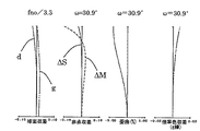
図1は本発明の実施例1のズームレンズの広角端(短焦点距離端)におけるレンズ断面図である。図2、図3はそれぞれ実施例1のズームレンズの広角端、望遠端(長焦点距離端)における収差図である。 FIG. 1 is a lens cross-sectional view at the wide-angle end (short focal length end) of the zoom lens according to Embodiment 1 of the present invention. 2 and 3 are aberration diagrams of the zoom lens of Example 1 at the wide-angle end and the telephoto end (long focal length end), respectively.
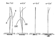
図4は本発明の実施例2のズームレンズの広角端におけるレンズ断面図である。図5、図6はそれぞれ実施例2のズームレンズの広角端、望遠端における収差図である。 FIG. 4 is a lens cross-sectional view at the wide-angle end of the zoom lens according to Embodiment 2 of the present invention. FIGS. 5 and 6 are aberration diagrams of the zoom lens of Example 2 at the wide-angle end and the telephoto end, respectively.
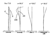
図7は本発明の実施例3のズームレンズの広角端におけるレンズ断面図である。図8、図9はそれぞれ実施例3のズームレンズの広角端、望遠端における収差図である。 FIG. 7 is a lens cross-sectional view at the wide-angle end of the zoom lens according to Embodiment 3 of the present invention. 8 and 9 are aberration diagrams of the zoom lens of Example 3 at the wide-angle end and the telephoto end, respectively.
図10は本発明の実施例4のズームレンズの広角端におけるレンズ断面図である。図11、図12はそれぞれ実施例4のズームレンズの広角端、望遠端における収差図である。 FIG. 10 is a lens cross-sectional view at the wide-angle end of the zoom lens according to a fourth embodiment of the present invention. 11 and 12 are aberration diagrams of the zoom lens of Example 4 at the wide-angle end and the telephoto end, respectively.
図13は本発明のズームレンズを備えるカメラ(撮像装置)の要部概略図である、各実施例のズームレンズはビデオカメラやデジタルカメラそして銀塩フィルムカメラ等の撮像装置に用いられる撮影レンズ系である。レンズ断面図において、左方が物体側(前方)で、右方が像側(後方)である。 FIG. 13 is a schematic diagram of a main part of a camera (imaging device) including the zoom lens of the present invention. The zoom lens of each embodiment is a photographing lens system used in an imaging device such as a video camera, a digital camera, a silver salt film camera, It is. In the lens cross-sectional view, the left side is the object side (front), and the right side is the image side (rear).
尚、各実施例のズームレンズをプロジェクター等の投射レンズとして用いても良い。このときは左方がスクリーン、右方が被投射画像となる。 In addition, you may use the zoom lens of each Example as projection lenses, such as a projector. At this time, the left side is the screen and the right side is the projected image.
レンズ断面図において、iは物体側からのレンズ群の順番を示し、Liは第iレンズ群である。 In the lens cross-sectional view, i indicates the order of the lens groups from the object side, and Li is the i-th lens group.
レンズ断面図において、L1は正の屈折力(光学的パワー=焦点距離の逆数)の第1レンズ群、L2は負の屈折力の第2レンズ群、L3は正の屈折力の第3レンズ群、L4は負の屈折力の第4レンズ群、L5は正の屈折力の第5レンズ群である。 In the lens cross-sectional view, L1 is a first lens group having a positive refractive power (optical power = reciprocal of focal length), L2 is a second lens group having a negative refractive power, and L3 is a third lens group having a positive refractive power. , L4 is a fourth lens group having a negative refractive power, and L5 is a fifth lens group having a positive refractive power.
SPは開口絞りであり、第3レンズ群L3の物体側に配置している。 SP is an aperture stop, which is disposed on the object side of the third lens unit L3.
Gは光学フィルター、フェースプレート、水晶ローパスフィルター、赤外カットフィルター等に相当する光学ブロックである。 G is an optical block corresponding to an optical filter, a face plate, a quartz low-pass filter, an infrared cut filter, or the like.
IPは像面であり、ビデオカメラやデジタルスチルカメラの撮影光学系として使用する際にはCCDセンサやCMOSセンサ等の固体撮像素子(光電変換素子)の撮像面に、銀塩フィルム用カメラのときはフィルム面に相当する感光面が置かれる。 IP is an image plane, and when used as a photographing optical system for a video camera or a digital still camera, on the imaging surface of a solid-state imaging device (photoelectric conversion device) such as a CCD sensor or a CMOS sensor, Is provided with a photosensitive surface corresponding to the film surface.
収差図において、d、gは各々d線及びg線、ΔM,ΔSはメリディオナル像面、サジタル像面、倍率色収差はg線によって表している。ωは半画角、fnoはFナンバーである。 In the aberration diagrams, d and g are d-line and g-line, ΔM and ΔS are meridional image surface, sagittal image surface, and lateral chromatic aberration are represented by g-line. ω is a half angle of view, and fno is an F number.
尚、以下の各実施例において広角端と望遠端は変倍用のレンズ群が機構上光軸上を移動可能な範囲の両端に位置したときのズーム位置をいう。 In the following embodiments, the wide-angle end and the telephoto end refer to zoom positions when the zoom lens units are positioned at both ends of a range in which the mechanism can move on the optical axis.
各実施例では、広角端から望遠端へのズーミングに際して矢印のように各レンズ群を移動させている。 In each embodiment, each lens group is moved as indicated by an arrow during zooming from the wide-angle end to the telephoto end.
具体的には、図1、図4の実施例1、2では広角端から望遠端へのズーミングに際して図中矢印のように第1レンズ群L1を像側に凸状の軌跡を描いて移動させている。又、第2レンズ群L2を像側に凸状の軌跡を描きながら移動させている。 Specifically, in Examples 1 and 2 of FIGS. 1 and 4, during zooming from the wide-angle end to the telephoto end, the first lens unit L1 is moved in a convex locus toward the image side as indicated by an arrow in the drawing. ing. The second lens unit L2 is moved while drawing a convex locus on the image side.
更に第3レンズ群L3を物体側へ、第4レンズ群L4を物体側へ移動させ、第5レンズ群L5を物体側に凸状の軌跡を描いて移動させている。 Further, the third lens unit L3 is moved toward the object side, the fourth lens unit L4 is moved toward the object side, and the fifth lens unit L5 is moved along a locus convex toward the object side.
開口絞りSPはズーミングに際し、第3レンズ群L3と一体的に移動している。 The aperture stop SP moves integrally with the third lens unit L3 during zooming.
又、第5レンズ群L5を光軸上移動させてフォーカスを行うリヤーフォーカス式を採用している。 In addition, a rear focus type is employed in which the fifth lens unit L5 is moved on the optical axis for focusing.
望遠端において無限遠物体から近距離物体へフォーカスを行う場合には矢印5cに示すように第5レンズ群L5を前方に繰り出すことによって行っている。第5レンズ群L5の実線の曲線5aと点線の曲線5bは各々無限遠物体と近距離物体にフォーカスしているときの広角端から望遠端へのズーミングに伴う際の像面変動を補正するための移動軌跡を示している。
When focusing from an infinitely distant object to a close object at the telephoto end, the fifth lens unit L5 is extended forward as indicated by an
図7の実施例3では、広角端から望遠端へのズーミングに際して図中矢印のように第1レンズ群L1を像側に凸状の軌跡を描いて移動させている。又、第2レンズ群L2を像側に凸状の軌跡を描きながら移動させている。 In Example 3 of FIG. 7, during zooming from the wide-angle end to the telephoto end, the first lens unit L1 is moved in a convex locus on the image side as indicated by an arrow in the drawing. The second lens unit L2 is moved while drawing a convex locus on the image side.
更に第3レンズ群L3を物体側へ移動させている。第4レンズ群L4と第5レンズ群L5は物体側に凸状の軌跡を描いて移動させている。 Further, the third lens unit L3 is moved to the object side. The fourth lens unit L4 and the fifth lens unit L5 are moved with a convex locus on the object side.
開口絞りSPは、各レンズ群とは独立に物体側へ移動している。フォーカスは第5レンズ群L5で行っており、フォーカスの際の移動軌跡は実施例1、2と同じである。 The aperture stop SP moves to the object side independently of each lens group. Focusing is performed by the fifth lens unit L5, and the movement locus during focusing is the same as in the first and second embodiments.
図10の実施例4は、図1、図4の実施例1、2に比べて広角端から望遠端へのズーミング時において第4レンズ群L4を像側に非直線的に移動させる点が異なっている。この他の構成は実施例1、2と同じである。 Example 4 of FIG. 10 differs from Examples 1 and 2 of FIGS. 1 and 4 in that the fourth lens unit L4 is moved non-linearly to the image side during zooming from the wide-angle end to the telephoto end. ing. Other configurations are the same as those in the first and second embodiments.
各実施例では、ズーミングに際し、広角端に比べて望遠端において第1レンズ群L1と第3レンズ群L3が物体側に位置する様に移動させている。これにより広角端におけるレンズ全長を短くしつつ、大きなズーム比(高ズーム比)が得られるようにしている。 In each embodiment, during zooming, the first lens unit L1 and the third lens unit L3 are moved closer to the object side at the telephoto end than at the wide-angle end. This makes it possible to obtain a large zoom ratio (high zoom ratio) while shortening the total lens length at the wide-angle end.
このとき第2レンズ群L2は像側に凸状の軌跡を描く事で、第3レンズ群L3の移動ストロークを確保している。 At this time, the second lens unit L2 ensures a moving stroke of the third lens unit L3 by drawing a convex locus on the image side.
各実施例では、ズーミングに際して第3レンズ群L3を物体側に移動させることにより、第3レンズ群L3と第4レンズ群L4にも変倍分担を持たせている。更に正の屈折力の第1レンズ群L1を物体側へ移動することで第2レンズ群L2に大きな変倍効果を持たせている。 In each embodiment, the third lens unit L3 and the fourth lens unit L4 are also assigned a variable magnification by moving the third lens unit L3 to the object side during zooming. Further, by moving the first lens unit L1 having positive refractive power toward the object side, the second lens unit L2 has a large zooming effect.
これにより第1レンズ群L1と、第2レンズ群L2の屈折力をあまり強くすることなく高いズーム比が得られるようにしている。 Thus, a high zoom ratio can be obtained without increasing the refractive power of the first lens unit L1 and the second lens unit L2.
また、各実施例においては、軽量な第5レンズ群L5を光軸上移動させてフォーカシングを行うリヤーフォーカス式を採用している。 In each embodiment, a rear focus type in which focusing is performed by moving the lightweight fifth lens unit L5 on the optical axis is employed.
各実施例では、軽量な第5レンズ群L5をフォーカスの為に移動することで迅速なフォーカスを、例えば自動焦点検出を容易にしている。また、フォーカスレンズ群の選択は第5レンズ群に限定されるものではなく、第4レンズ群L4を光軸方向に移動させることによっても達成可能である。 In each embodiment, quick focusing, for example, automatic focus detection, is facilitated by moving the lightweight fifth lens unit L5 for focusing. The selection of the focus lens group is not limited to the fifth lens group, and can be achieved by moving the fourth lens group L4 in the optical axis direction.
各実施例においては、第3レンズ群L3を光軸と垂直方向の成分を持つように移動させて光学系全体が振動したときの像ぶれを補正するようにしている。 In each embodiment, the third lens unit L3 is moved so as to have a component perpendicular to the optical axis so as to correct image blur when the entire optical system vibrates.
これにより、可変頂角プリズム等の光学部材や防振のためのレンズ群を新たに付加することなく防振を行うようにし、光学系全体が大型化するのを防止している。 As a result, image stabilization is performed without newly adding an optical member such as a variable apex angle prism or a lens group for image stabilization, and the entire optical system is prevented from being enlarged.
なお、実施例1、2、4においては、開口絞りSPはズーミング時に第3レンズ群L3と一体にて移動している。このため、移動/可動で分けられる群数が少なくなり、メカ構造が簡素化しやすくなる。 In Examples 1, 2, and 4, the aperture stop SP moves integrally with the third lens unit L3 during zooming. For this reason, the number of groups divided by movement / movability is reduced, and the mechanical structure is easily simplified.
一方、実施例3では、開口絞りSPはズーミングに際して第3レンズ群L3と別体で移動している。これによって、広画角域での入射瞳位置をより物体側に近づけるようにして、前玉径(第1レンズ群L1の有効径)を小さくする事に大きく寄与している。 On the other hand, in Example 3, the aperture stop SP moves separately from the third lens unit L3 during zooming. This greatly contributes to reducing the front lens diameter (the effective diameter of the first lens unit L1) by making the entrance pupil position in the wide field angle region closer to the object side.
尚、開口絞りSPを固定とする場合は絞りユニットを移動させる必要がないため、ズーミングの際、駆動させるアクチュエータの駆動トルクを小さく設定できる省電力化の点で有利となる。 When the aperture stop SP is fixed, it is not necessary to move the aperture unit, and this is advantageous in terms of power saving because the driving torque of the actuator to be driven can be set small during zooming.
次に各レンズ群のレンズ構成に関して説明する。 Next, the lens configuration of each lens group will be described.
まず第1レンズ群L1について説明する。第1レンズ群L1は有効レンズ径が大きくなるので、レンズ枚数が少ない方が小型、軽量化のために好ましい。 First, the first lens unit L1 will be described. Since the first lens unit L1 effective lens diameter increases, better lenses is small size, good preferable for weight reduction.
各実施例においては、負レンズと正レンズの各1枚を接合した接合レンズと、正レンズを加えて全体として3枚のレンズで第1レンズ群L1を構成している。これにより高ズーム比化を図る際に発生する球面収差と色収差を抑制している。 In each embodiment, the first lens unit L1 is composed of a cemented lens obtained by cementing one each of a negative lens and a positive lens and a positive lens, and a total of three lenses. This suppresses spherical aberration and chromatic aberration that occur when a high zoom ratio is achieved.
次に第2レンズ群L2について説明する。第2レンズ群L2は実施例1、2において、物体側の面が凸でメニスカス形状の負レンズ、両レンズ面が凹形状の負レンズ、物体側の面が凸形状の正レンズの独立した3つのレンズより構成している。これによってズーミング時の(ズーミングの際の)収差変動を少なくし、特に広角端における歪曲収差及び望遠端における球面収差を良好に補正している。 Next, the second lens unit L2 will be described. In the first and second embodiments, the second lens unit L2 is independent of the negative lens having a convex surface on the object side and a meniscus shape, a negative lens having a concave shape on both lens surfaces, and a positive lens having a convex shape on the object side. It consists of two lenses. As a result, aberration fluctuations during zooming (during zooming) are reduced, and in particular, distortion at the wide-angle end and spherical aberration at the telephoto end are corrected well.
実施例3においては、第2レンズ群L2を物体側より順に3枚の負レンズと1枚の正レンズにより構成している。これにより、軸外収差の補正を良好に行い、広角端での画角の増大に適したレンズ群構成としている。 In Example 3, the second lens unit L2 includes three negative lenses and one positive lens in order from the object side. Thereby, the correction of off-axis aberration is performed satisfactorily, and a lens group configuration suitable for increasing the angle of view at the wide-angle end is obtained.
実施例4においては、第2レンズ群L2を物体側より順に2枚の負レンズと、正レンズと負レンズの接合レンズにより構成している。これにより、ズーミング時の色収差の変動を抑制するのに有利なレンズ群構成としている。 In Example 4, the second lens unit L2 includes two negative lenses in order from the object side, and a cemented lens of a positive lens and a negative lens. Thus, the lens unit configuration is advantageous for suppressing fluctuations in chromatic aberration during zooming.
次に第3レンズ群L3について説明する。第3レンズ群L3は実施例1、2、3において2枚の正レンズと像面側の面が凹形状の負レンズを含むように構成している。これにより、第2レンズ群L2と第3レンズ群L3間の主点間隔を小さくすることで第3レンズ群L3以降のレンズ長を短縮している。 Next, the third lens unit L3 will be described. In the first, second, and third embodiments, the third lens unit L3 is configured to include two positive lenses and a negative lens having a concave surface on the image side. Thereby, the lens length after the third lens unit L3 is shortened by reducing the principal point interval between the second lens unit L2 and the third lens unit L3.
また、これらの各実施例においては第3レンズ群L3が1以上の非球面を有するようにしている。これによってズーミングに伴う収差変動を良好に補正している。 In each of these embodiments, the third lens unit L3 has one or more aspheric surfaces. As a result, aberration fluctuations accompanying zooming are corrected satisfactorily.
更に実施例3では、負レンズと正レンズから成る接合レンズを用いる事で、ズーミング時の色収差の変動を抑制すると伴に、第3レンズ群L3を光軸から偏芯させて防振動作を行う際の、偏芯による収差発生を抑えている。 Further, in Example 3, by using a cemented lens composed of a negative lens and a positive lens, the variation in chromatic aberration during zooming is suppressed, and at the same time, the third lens unit L3 is decentered from the optical axis to perform an image stabilization operation. The occurrence of aberration due to decentration is suppressed.
実施例4において第3レンズ群L3は他の実施例とは異なり、像側に凸面を有するメニスカス状の負レンズと正レンズとを接合している。この形状は軸上光束の収差補正に効果的であり、Fナンバーを小さく明るくするのに適している。 In the fourth embodiment, unlike the other embodiments, the third lens unit L3 cements a meniscus negative lens having a convex surface on the image side and a positive lens. This shape is effective for correcting the aberration of the axial beam, and is suitable for making the F number small and bright.
次に第4レンズ群L4について説明する。第4レンズ群L4は実施例1〜4において、物体側の面が凸形状の1枚の負レンズ或いは、正レンズと負レンズの接合レンズを有するようにしている。実施例4においては、非球面を採用する事でズーミング中の収差変動を抑制している。 Next, the fourth lens unit L4 will be described. In the first to fourth embodiments, the fourth lens unit L4 includes one negative lens having a convex object-side surface or a cemented lens of a positive lens and a negative lens. In the fourth embodiment, aberration variation during zooming is suppressed by using an aspherical surface.
次に第5レンズ群L5について説明する。第5レンズ群L5は、1枚の正レンズで構成する場合は分散の小さい硝材を用い、フォーカス時の色収差の変動を抑制している。又、第5レンズ群L5を2枚以上のレンズで構成する場合は、接合レンズを有するようにして、同様に色収差の変動を抑制している。 Next, the fifth lens unit L5 will be described. When the fifth lens unit L5 is composed of a single positive lens, a glass material with low dispersion is used to suppress fluctuations in chromatic aberration during focusing. In the case where the fifth lens unit L5 is composed of two or more lenses, a variation in chromatic aberration is similarly suppressed by having a cemented lens.
各実施例では以上のようなレンズ構成とすることで、高ズーム比でありながら前玉径が小さく及び沈胴長が短くコンパクトなズームレンズを達成している。 In each embodiment, the above-described lens configuration achieves a compact zoom lens with a small front lens diameter and a short retractable length while having a high zoom ratio.
各実施例では以上のような構成とすることで高ズーム比でありながら全系がコンパクトなズームレンズを達成している。各実施例において、更に好ましくは以下の条件式のうち、少なくとも1つを満足するのが良い。これによれば、条件式に対応した効果を得ることができる。 In each embodiment, the above-described configuration achieves a zoom lens in which the entire system is compact while maintaining a high zoom ratio. In each embodiment, it is more preferable that at least one of the following conditional expressions is satisfied. According to this, the effect corresponding to the conditional expression can be obtained.
第2レンズ群L2の焦点距離をf2とする。ズームレンズの広角端における全系の焦点距離をfwとする。望遠端における全系の焦点距離をftとする。第2レンズ群L2の広角端と望遠端における結像倍率を各々β2w、β2t、第3レンズ群L3の広角端と望遠端における結像倍率を各々β3w、β3tとする。 Let the focal length of the second lens unit L2 be f2. Let fw be the focal length of the entire system at the wide-angle end of the zoom lens. Let ft be the focal length of the entire system at the telephoto end. The imaging magnifications at the wide-angle end and the telephoto end of the second lens unit L2 are β2w and β2t, respectively, and the imaging magnifications at the wide-angle end and the telephoto end of the third lens unit L3 are β3w and β3t, respectively.
広角端から望遠端へのズーミングにおける第1レンズ群L1の移動量をm1とする。同じく第2レンズ群L2の移動量をm2とする。このときの移動量は、移動レンズ群の広角端での像面に対する位置と、望遠端での像面に対する位置との差分であり、符号は、広角端に対し望遠端で像側に変位した場合を正とする。 The amount of movement of the first lens unit L1 during zooming from the wide-angle end to the telephoto end is m1. Similarly, the moving amount of the second lens unit L2 is m2. The amount of movement at this time is the difference between the position of the moving lens group relative to the image plane at the wide-angle end and the position relative to the image plane at the telephoto end, and the sign is displaced toward the image side at the telephoto end relative to the wide-angle end. The case is positive.
全系の焦点距離 Focal length of the entire system

なるズーム位置における第5レンズ群L5の最も像側の面(屈折力のある面)から像面までの空気換算長をbfmとする。 Let bfm be the air-converted length from the most image side surface (surface having refractive power) to the image surface of the fifth lens unit L5 at the zoom position.
望遠端における該第5レンズ群L5の最も像側の面(屈折力のある面)から像面までの空気換算長をbftとする。このとき、 The air-converted length from the most image side surface (surface having refractive power) of the fifth lens unit L5 at the telephoto end to the image surface is bft. At this time,
なる条件を満足するのが良い。 It is good to satisfy the condition.
本発明において、 条件式(1)は第2レンズ群L2の焦点距離を適切に選択する事で、ズームレンズの高ズーム比化を実現する条件式である。条件式(1)の下限を超えて第2レンズ群L2の焦点距離が小さくなると、小さな移動ストロークでの高ズーム比化が可能となる。しかしながら、屈折力の増加に伴う収差が増大し、これを抑制するのが困難となる。 In the present invention, the conditional expression (1) is a conditional expression for realizing a high zoom ratio of the zoom lens by appropriately selecting the focal length of the second lens unit L2. When the lower limit of conditional expression (1) is exceeded and the focal length of the second lens unit L2 becomes small, a high zoom ratio can be achieved with a small movement stroke. However, the aberration accompanying the increase in refractive power increases, and it is difficult to suppress this.
上限を超えて第2レンズ群L2の焦点距離が大きくなると、高ズーム比化のためにはレンズ群の移動量を大きくする必要が生じる。そうすると、レンズ全系の小型化が困難となる。 If the focal length of the second lens unit L2 increases beyond the upper limit, it is necessary to increase the amount of movement of the lens unit in order to increase the zoom ratio. This makes it difficult to downsize the entire lens system.
また、本発明において好ましくは、
2.23≦(β2t/β2w)/(β3t/β3w)<9.0・・・(2)
−7.0<m1/m2<−1.0 ・・・(3)
1.2<bfm/bft<3.0 ・・・(4)
なる条件のうち1以上を満足するのが良い。
In the present invention, preferably,
2.23 ≦ (β2t / β2w) / (β3t / β3w) <9.0 (2)
−7.0 <m1 / m2 <−1.0 (3)
1.2 <bfm / bft <3.0 (4)
It is preferable to satisfy one or more of the following conditions.
各実施例では、それぞれの条件式を満足することによって、それに応じた効果を得ている。 In each embodiment, by satisfying each conditional expression, an effect corresponding to the conditional expression is obtained.
次に各条件式の技術的な意味について説明する。 Next, the technical meaning of each conditional expression will be described.
条件式(2)は第2レンズ群L2と第3レンズ群L3の変倍負担を定めたものである。通常、各実施例のズームタイプにおいては主変倍レンズ群は第2レンズ群である。条件式(2)の下限を超えて第2レンズ群L2の変倍負担が小さくなると、高ズーム比化が困難となる。 Conditional expression (2) defines the variable magnification load of the second lens unit L2 and the third lens unit L3. Usually, in the zoom type of each embodiment, the main variable magnification lens group is the second lens group. If the zoom ratio of the second lens unit L2 is reduced beyond the lower limit of conditional expression (2), it is difficult to achieve a high zoom ratio.
逆に条件式(2)の上限を超えると第2レンズ群L2の変倍寄与が大きくなりすぎる。この結果、ズーミング時の収差変動や偏芯敏感度が増加してくるので、好ましくない。 Conversely, if the upper limit of conditional expression (2) is exceeded, the variable power contribution of the second lens unit L2 becomes too large. As a result, aberration fluctuation and decentering sensitivity during zooming increase, which is not preferable.
条件式(3)は第1レンズ群L1と第2レンズ群L2のズーミング時の移動量の比率を適切に定めたものである。条件式(3)の下限を超えると第1レンズ群L1と比較して第2レンズ群L2の移動量が大きくなりすぎるため、広角端において最も物体側の面と絞りSPとの間隔が大きくなり、入射瞳位置が、より像側になってくる。 Conditional expression (3) appropriately determines the ratio of the amount of movement during zooming between the first lens unit L1 and the second lens unit L2. If the lower limit of conditional expression (3) is exceeded, the amount of movement of the second lens unit L2 becomes too large compared to the first lens unit L1, and therefore the distance between the surface closest to the object side and the stop SP at the wide angle end becomes large. The entrance pupil position is closer to the image side.
結果として広角端近傍で軸外光線の入射高が大きくなり、前玉径が増大してくるので小型化の目的には適さない。 As a result, the incident height of off-axis rays increases near the wide-angle end and the front lens diameter increases, which is not suitable for downsizing purposes.
条件式(3)の上限を超えると、第1レンズ群L1の移動量が大きくなりすぎるため、望遠端において軸外光線の入射高が大きくなり、前玉径が増大してくるので好ましくない。 Exceeding the upper limit of conditional expression (3) is not preferable because the amount of movement of the first lens unit L1 becomes too large, and the incident height of off-axis rays increases at the telephoto end and the front lens diameter increases.
条件式(4)は、ズーミングに伴う第5レンズ群L5と像面との間隔を適正化したものである。 Conditional expression (4) optimizes the distance between the fifth lens unit L5 and the image plane that accompanies zooming.
各実施例のズームレンズにおいて、高ズーム比化を図るためにレンズ群の繰出し量を十分に確保するためには、望遠端近傍で第4レンズ群L4と第5レンズ群L5の間隔が充分に確保される事が望ましい。 In the zoom lens of each embodiment, in order to secure a sufficient amount of extension of the lens unit in order to achieve a high zoom ratio, the distance between the fourth lens unit L4 and the fifth lens unit L5 is sufficiently close in the vicinity of the telephoto end. It is desirable to be secured.
単純にレンズ群間隔を広げると、レンズ全長の増大に繋がるので、ズーム中間域で第5レンズ群L5が物体側へ繰出し、望遠端近傍で像側へ繰り込む軌跡が好ましい。 If the distance between the lens groups is simply widened, the total length of the lens is increased. Therefore, it is preferable that the fifth lens group L5 extends toward the object side in the zoom intermediate range and retracts toward the image side near the telephoto end.
条件式(5)の上下限値は、高ズーム比化を実現しつつ、コンパクト化(レンズ全長の短縮化)を図るための条件である。下限を超えると至近被写体へのフォーカスの際の繰出し量の確保が困難になると同時に、第5レンズ群L5の変倍負担が減倍方向に働くため、高ズーム比化には不利となる。 The upper and lower limit values of the conditional expression (5) are conditions for achieving compactness (shortening the total lens length) while realizing a high zoom ratio. If the lower limit is exceeded, it becomes difficult to secure the amount of extension when focusing on the closest subject, and at the same time, the variable magnification burden of the fifth lens unit L5 acts in the reduction direction, which is disadvantageous for achieving a high zoom ratio.
反対に上限を超えると、高ズーム比化には有利であるが、フォーカス敏感度が低下するために、部品公差や温度変化によるピント変動を第5レンズ群L5で補正する事が困難になる。 On the contrary, if the upper limit is exceeded, it is advantageous for achieving a high zoom ratio, but the focus sensitivity is lowered, so that it is difficult to correct the focus fluctuation due to component tolerance or temperature change by the fifth lens unit L5.
尚、各実施例において、更に収差補正及びズーミングの際の収差変動を小さくしつつ高ズーム比化を図るには、条件式(1)〜(4)の数値範囲を次の如く設定するのが良い。 In each embodiment, in order to achieve a high zoom ratio while further reducing aberration fluctuation during aberration correction and zooming, the numerical ranges of conditional expressions (1) to (4) are set as follows. good.
2.23≦(β2t/β2w)/(β3t/β3w)<7.0・・・(2a)
−5.0<m1/m2<−1.8・・・(3a)
1.3<bfm/bft<2.5・・・(4a)
以上のように各実施例によれば、ズーミングにおける各レンズ群の移動量と各レンズ群の屈折力等を適切に設定することで、高ズーム比にもかかわらずレンズ全長の短い小型化のズームレンズを達成することが出来る。
2.23 ≦ (β2t / β2w) / (β3t / β3w) <7.0 (2a)
−5.0 <m1 / m2 <−1.8 (3a)
1.3 <bfm / bft <2.5 (4a)
As described above, according to each embodiment, by appropriately setting the amount of movement of each lens unit and the refractive power of each lens unit in zooming, a compact zoom with a short overall lens length despite a high zoom ratio. Lens can be achieved.
特に広角端から望遠端に至る全ズーム範囲にわたり良好なる光学性能を有するズームレンズを得ることができる。 In particular, it is possible to obtain a zoom lens having good optical performance over the entire zoom range from the wide-angle end to the telephoto end.
次に、本発明の実施例1〜4に各々対応する数値実施例1〜4を示す。各数値実施例においてiは物体側からの光学面の順序を示す。riは第i番目の光学面(第i面)の曲率半径、diは第i面と第i+1面との間の間隔、niとνiはそれぞれd線に対する第i番目の光学部材の材料の屈折率、アッベ数を示す。 Next, numerical examples 1 to 4 corresponding to the first to fourth embodiments of the present invention will be described. In each numerical example, i indicates the order of the optical surfaces from the object side. ri is the radius of curvature of the i-th optical surface (i-th surface), di is the distance between the i-th surface and the i + 1-th surface, and ni and νi are the refractions of the material of the i-th optical member with respect to the d-line, respectively. Indicates the rate and Abbe number.
またkを離心率、B、C、D、Eを非球面係数、光軸からの高さhの位置での光軸方向の変位を面頂点を基準にしてxとするとき、非球面形状は、
x=(h2/R)/[1+[1−(1+k)(h/R)2]1/2]+Bh4+Ch6
+Dh8+Eh10
で表示される。
Further, when k is an eccentricity, B, C, D, and E are aspheric coefficients, and the displacement in the optical axis direction at the position of the height h from the optical axis is x with respect to the surface vertex, the aspheric shape is ,
x = (h 2 / R) / [1+ [1- (1 + k) (h / R) 2 ] 1/2 ] + Bh 4 + Ch 6
+ Dh 8 + Eh 10
Is displayed.
但しRは曲率半径である。また例えば「E−Z」の表示は「10−Z」を意味する。 Where R is the radius of curvature. Also for example, a display of the "E-Z" means "10 -Z".
数値実施例において最後の2つの面は、フィルター、フェースプレート等の光学ブロックの面である。 In the numerical example, the last two surfaces are surfaces of an optical block such as a filter and a face plate.
また、各数値実施例における上述した条件式との対応を表1に示す。BFは最終面から像面までの距離である。 Table 1 shows the correspondence with the above-described conditional expressions in each numerical example. BF is the distance from the final surface to the image surface.
[数値実施例1]
単位 mm
面データ
面番号 r d nd νd
1 70.9695 1.300 1.806100 33.3
2 32.9073 4.500 1.496999 81.5
3 -111.7649 0.100 1.
4 26.7420 2.400 1.603112 60.6
5 52.6149 可変
6 28.2339 0.700 1.882997 40.8
7 6.1390 2.600 1.
8 -22.7407 0.600 1.696797 55.5
9 23.8455 0.400 1.
10 12.0313 1.700 1.922860 18.9
11 37.6285 可変
12 (絞り) 1.500 1.
13 13.8130 2.000 1.693500 53.2
14* -95.8833 3.000 1.
15 51.5950 0.600 1.846660 23.9
16 10.7382 0.272 1.
17 11.7596 1.700 1.603112 60.6
18 -18.7628 可変
19 29.5071 1.200 1.761821 26.5
20 51.5358 0.600 1.603112 60.6
21 10.0344 可変
22 18.6244 3.200 1.804000 46.6
23 -12.1545 0.600 1.805181 25.4
24 -54.2790 可変 1.
25 ∞ 1.200 1.516330 64.1
26 ∞ BF
非球面データ
(第14面)k=-1.41507E+03 B=-5.53469E-05 C= 7.53066E-06
D-1.49270E-07
各種データ
ズーム比 14.75
広角 中間 望遠
焦点距離 6.10 23.40 89.99
Fナンバー 2.90 3.26 4.29
画角 30.3 8.7 2.3
像高 3.6 3.6 3.6
レンズ全長 67.99 82.94 98.99
BF 8.27 14.63 6.14
d5 0.70 23.50 38.58
d11 19.78 3.83 1.53
d18 1.50 3.55 3.65
d21 8.76 8.45 20.13
d24 5.58 11.94 3.44
ズームレンズ群データ
群 始面 焦点距離
1 1 56.05
2 6 -8.53
3 12 14.05
4 19 -27.98
5 22 17.68
[数値実施例2]
単位 mm
面データ
面番号 r d nd νd
1 37.4429 1.100 1.805181 25.4
2 24.2372 3.300 1.487490 70.2
3 110.4237 0.200 1.
4 32.7375 2.500 1.696797 55.5
5 153.2020 可変
6 26.3687 0.800 1.804000 46.6
7 6.5704 3.89340 1.
8 -18.9046 0.700 1.603112 60.6
9 26.4998 0.700 1.
10 13.7742 1.600 1.922860 18.9
11 30.6924 可変
12 (絞り) 2.200 1.
13* 9.2003 3.000 1.583126 59.4
14 -61.1241 2.400 1.
15 25.9673 0.700 1.846660 23.9
16 8.7391 0.800 1.
17 25.1623 2.000 1.487490 70.2
18 -21.3178 可変
19 38.4933 1.000 1.487490 70.2
20 22.0000 可変
21 13.4000 2.000 1.487490 70.2
22 -175.1720 可変
23 ∞ 0.800 1.498310 65.1
24 ∞ BF
非球面データ
(第13面)k=-2.49846 B= 2.27368E-4 C=-6.59585E-7 D=-9.99386E-8
E= 3.92484E-9
各種データ
ズーム比 13.33
広角 中間 望遠
焦点距離 6.00 21.90 79.99
Fナンバー 3.34 3.84 4.95
画角 30.9 9.3 2.6
像高 3.6 3.6 3.6
レンズ全長 69.63 77.05 89.11
BF 10.62 15.65 7.45
d5 0.80 18.73 30.24
d11 24.53 7.94 1.69
d18 2.16 2.31 5.57
d20 2.63 3.73 15.27
d22 5.10 10.13 1.92
ズームレンズ群データ
群 始面 焦点距離
1 1 48.43
2 6 -9.05
3 12 17.91
4 19 -107.46
5 21 25.62
[数値実施例3]
単位 mm
面データ
面番号 r d nd νd
1 75.6161 1.900 1.806100 33.3
2 38.4904 5.500 1.496999 81.5
3 1574.3184 0.200 1.
4 40.1987 4.300 1.603112 60.6
5 195.3611 可変
6 43.9723 1.000 1.882997 40.8
7 10.3266 2.700 1.
8 25.5214 0.850 1.834807 42.7
9 10.7219 3.600 1.
10 -23.5964 0.800 1.834807 42.7
11 -171.2663 0.116 1.
12 21.7930 2.250 1.922860 18.9
13 487.0594 可変
14 (絞り) 可変
15* 12.0562 3.450 1.583126 59.4
16 -82.0366 2.800 1.
17 42.0042 1.150 1.603420 38.0
18 12.5862 0.300 1.
19 21.2243 0.800 2.003300 28.3
20 8.5720 2.150 1.719995 50.2
21 -58.7695 可変
22 55.2648 1.000 1.761821 26.5
23 69.9209 0.600 1.603112 60.6
24 18.0000 可変
25 20.2436 4.000 1.772499 49.6
26 -9.8847 0.600 1.806100 33.3
27 -50.8951 可変
28 ∞ 0.800 1.516330 64.1
29 ∞ BF
非球面データ
(第15面)k= 2.38663E-01 B=-9.34063E-05 C=-4.27892E-07 D= 3.73118E-08
E=-1.75451E-09
各種データ
ズーム比 17.48
広角 中間 望遠
焦点距離 5.15 21.52 89.99
Fナンバー 2.87 3.85 5.22
画角 36.8 10.1 2.4
像高 3.9 3.9 3.9
レンズ全長 92.73 102.23 125.15
BF 10.53 17.93 10.75
d5 0.90 25.33 46.76
d13 25.63 5.06 1.76
d14 10.21 3.52 1.78
d21 1.00 4.56 13.30
d24 4.40 5.77 10.74
d27 8.00 15.39 8.22
ズームレンズ群データ
群 始面 焦点距離
1 1 70.34
2 6 -10.20
3 15 19.96
4 22 -46.37
5 25 20.27
[数値実施例4]
単位 mm
面データ
面番号 r d nd νd
1 129.3681 3.000 1.846660 23.9
2 76.8780 7.500 1.583126 59.4
3 3331.9206 0.200 1.
4 74.1874 4.500 1.696797 55.5
5 138.3490 可変
6 52.4076 1.500 1.834807 42.7
7 13.9045 7.800 1.
8 -96.1039 1.100 1.772499 49.6
9 43.8328 0.700 1.
10 23.0329 4.400 1.846660 23.9
11 -166.9463 1.100 1.834807 42.7
12 40.9356 可変
13 (絞り) 2.850 1.
14 55.4646 2.600 1.696797 55.5
15 -37.4229 0.500 1.
16 143.4269 3.400 1.603112 60.6
17 -18.5766 0.800 1.846660 23.9
18 -52.0513 可変.
19* -16.4692 2.500 1.688931 31.1
20 -12.3790 1.000 1.516330 64.1
21 202.3067 可変
22 19.1851 5.000 1.696797 55.5
23 -43.2878 0.200 1.
24 15.6598 5.000 1.496999 81.5
25 -19.3663 0.800 1.806100 33.3
26 18.4800 1.300 1.
27 -180.4304 2.400 1.583126 59.4
28* -51.6191 可変
29 ∞ 3.500 1.516330 64.2
30 ∞ BF
非球面データ
(第19面)k= 1.48433E-1 B= 1.54153E-5 C= 3.68917E-7
D= -7.67521E-9
(第28面)k=-7.84496E+1 B= 5.99482E-5 C= 5.10736E-7
D= -1.13419E-9
各種データ
ズーム比 12.11
広角 中間 望遠
焦点距離 7.44 25.87 90.17
Fナンバー 2.50 3.10 3.60
画角 36.5 12.0 3.5
像高 5.5 5.5 5.5
レンズ全長 128.58 148.52 192.40
BF 11.59 14.85 10.57
d5 1.00 39.98 85.65
d12 40.33 9.34 1.80
d18 1.29 14.03 22.87
d21 14.22 10.17 11.35
d28 3.70 6.96 2.68
ズームレンズ群データ
群 始面 焦点距離
1 1 135.38
2 6 -17.77
3 13 26.64
4 19 -33.58
5 22 21.41
[Numerical Example 1]
Unit mm
Surface data surface number rd nd νd
1 70.9695 1.300 1.806100 33.3
2 32.9073 4.500 1.496999 81.5
3 -111.7649 0.100 1.
4 26.7420 2.400 1.603112 60.6
5 52.6149 Variable
6 28.2339 0.700 1.882997 40.8
7 6.1390 2.600 1.
8 -22.7407 0.600 1.696797 55.5
9 23.8455 0.400 1.
10 12.0313 1.700 1.922860 18.9
11 37.6285 Variable
12 (Aperture) 1.500 1.
13 13.8130 2.000 1.693500 53.2
14 * -95.8833 3.000 1.
15 51.5950 0.600 1.846660 23.9
16 10.7382 0.272 1.
17 11.7596 1.700 1.603112 60.6
18 -18.7628 Variable
19 29.5071 1.200 1.761821 26.5
20 51.5358 0.600 1.603112 60.6
21 10.0344 Variable
22 18.6244 3.200 1.804000 46.6
23 -12.1545 0.600 1.805181 25.4
24 -54.2790 Variable 1.
25 ∞ 1.200 1.516 330 64.1
26 ∞ BF
Aspheric data (14th surface) k = -1.41507E + 03 B = -5.53469E-05 C = 7.53066E-06
D-1.49270E-07
Various data zoom ratio 14.75
Wide angle Medium telephoto focal length 6.10 23.40 89.99
F number 2.90 3.26 4.29
Angle of view 30.3 8.7 2.3
Image height 3.6 3.6 3.6
Total lens length 67.99 82.94 98.99
BF 8.27 14.63 6.14
d5 0.70 23.50 38.58
d11 19.78 3.83 1.53
d18 1.50 3.55 3.65
d21 8.76 8.45 20.13
d24 5.58 11.94 3.44
Zoom lens group data group Start surface Focal length
1 1 56.05
2 6 -8.53
3 12 14.05
4 19 -27.98
5 22 17.68
[Numerical Example 2]
Unit mm
Surface data surface number rd nd νd
1 37.4429 1.100 1.805181 25.4
2 24.2372 3.300 1.487490 70.2
3 110.4237 0.200 1.
4 32.7375 2.500 1.696797 55.5
5 153.2020 Variable
6 26.3687 0.800 1.804000 46.6
7 6.5704 3.89340 1.
8 -18.9046 0.700 1.603112 60.6
9 26.4998 0.700 1.
10 13.7742 1.600 1.922860 18.9
11 30.6924 Variable
12 (Aperture) 2.200 1.
13 * 9.2003 3.000 1.583126 59.4
14 -61.1241 2.400 1.
15 25.9673 0.700 1.846660 23.9
16 8.7391 0.800 1.
17 25.1623 2.000 1.487490 70.2
18 -21.3178 Variable
19 38.4933 1.000 1.487490 70.2
20 22.0000 Variable
21 13.4000 2.000 1.487490 70.2
22 -175.1720 Variable
23 ∞ 0.800 1.498310 65.1
24 ∞ BF
Aspheric data (13th surface) k = -2.49846 B = 2.27368E-4 C = -6.59585E-7 D = -9.99386E-8
E = 3.92484E-9
Various data zoom ratio 13.33
Wide angle Medium Telephoto focal length 6.00 21.90 79.99
F number 3.34 3.84 4.95
Angle of view 30.9 9.3 2.6
Image height 3.6 3.6 3.6
Total lens length 69.63 77.05 89.11
BF 10.62 15.65 7.45
d5 0.80 18.73 30.24
d11 24.53 7.94 1.69
d18 2.16 2.31 5.57
d20 2.63 3.73 15.27
d22 5.10 10.13 1.92
Zoom lens group data group Start surface Focal length
1 1 48.43
2 6 -9.05
3 12 17.91
4 19 -107.46
5 21 25.62
[Numerical Example 3]
Unit mm
Surface data surface number rd nd νd
1 75.6161 1.900 1.806100 33.3
2 38.4904 5.500 1.496999 81.5
3 1574.3184 0.200 1.
4 40.1987 4.300 1.603112 60.6
5 195.3611 Variable
6 43.9723 1.000 1.882997 40.8
7 10.3266 2.700 1.
8 25.5214 0.850 1.834807 42.7
9 10.7219 3.600 1.
10 -23.5964 0.800 1.834807 42.7
11 -171.2663 0.116 1.
12 21.7930 2.250 1.922860 18.9
13 487.0594 Variable
14 (Aperture) Variable
15 * 12.0562 3.450 1.583126 59.4
16 -82.0366 2.800 1.
17 42.0042 1.150 1.603420 38.0
18 12.5862 0.300 1.
19 21.2243 0.800 2.003 300 28.3
20 8.5 720 2.150 1.719995 50.2
21 -58.7695 Variable
22 55.2648 1.000 1.761821 26.5
23 69.9209 0.600 1.603112 60.6
24 18.0000 Variable
25 20.2436 4.000 1.772499 49.6
26 -9.8847 0.600 1.806100 33.3
27 -50.8951 Variable
28 ∞ 0.800 1.516 330 64.1
29 ∞ BF
Aspheric data (15th surface) k = 2.38663E-01 B = -9.34063E-05 C = -4.27892E-07 D = 3.73118E-08
E = -1.75451E-09
Various data zoom ratio 17.48
Wide-angle Medium Telephoto focal length
F number 2.87 3.85 5.22
Angle of view 36.8 10.1 2.4
Image height 3.9 3.9 3.9
Total lens length 92.73 102.23 125.15
BF 10.53 17.93 10.75
d5 0.90 25.33 46.76
d13 25.63 5.06 1.76
d14 10.21 3.52 1.78
d21 1.00 4.56 13.30
d24 4.40 5.77 10.74
d27 8.00 15.39 8.22
Zoom lens group data group Start surface Focal length
1 1 70.34
2 6 -10.20
3 15 19.96
4 22 -46.37
5 25 20.27
[Numerical Example 4]
Unit mm
Surface data surface number rd nd νd
1 129.3681 3.000 1.846660 23.9
2 76.8780 7.500 1.583126 59.4
3 3331.9206 0.200 1.
4 74.1874 4.500 1.696797 55.5
5 138.3490 Variable
6 52.4076 1.500 1.834807 42.7
7 13.9045 7.800 1.
8 -96.1039 1.100 1.772499 49.6
9 43.8328 0.700 1.
10 23.0329 4.400 1.846660 23.9
11 -166.9463 1.100 1.834807 42.7
12 40.9356 Variable
13 (Aperture) 2.850 1.
14 55.4646 2.600 1.696797 55.5
15 -37.4229 0.500 1.
16 143.4269 3.400 1.603112 60.6
17 -18.5766 0.800 1.846660 23.9
18 -52.0513 Variable.
19 * -16.4692 2.500 1.688931 31.1
20 -12.3790 1.000 1.516330 64.1
21 202.3067 Variable
22 19.1851 5.000 1.696797 55.5
23 -43.2878 0.200 1.
24 15.6598 5.000 1.496999 81.5
25 -19.3663 0.800 1.806 100 33.3
26 18.4800 1.300 1.
27 -180.4304 2.400 1.583 126 59.4
28 * -51.6191 Variable
29 ∞ 3.500 1.516 330 64.2
30 ∞ BF
Aspheric data (19th surface) k = 1.48433E-1 B = 1.54153E-5 C = 3.68917E-7
D = -7.67521E-9
(Section 28) k = -7.84496E + 1 B = 5.99482E-5 C = 5.10736E-7
D = -1.13419E-9
Various data zoom ratio 12.11
Wide angle Medium Telephoto focal length
F number 2.50 3.10 3.60
Angle of view 36.5 12.0 3.5
Image height 5.5 5.5 5.5
Total lens length 128.58 148.52 192.40
BF 11.59 14.85 10.57
d5 1.00 39.98 85.65
d12 40.33 9.34 1.80
d18 1.29 14.03 22.87
d21 14.22 10.17 11.35
d28 3.70 6.96 2.68
Zoom lens group data group Start surface Focal length
1 1 135.38
2 6 -17.77
3 13 26.64
4 19 -33.58
5 22 21.41
次に各実施例に示したようなズームレンズを撮影光学系として用いたデジタルスチルカメラの実施形態を図13を用いて説明する。 Next, an embodiment of a digital still camera using a zoom lens as shown in each embodiment as a photographing optical system will be described with reference to FIG.
図13において、20はカメラ本体、21は実施例1〜4で説明したいずれかのズームレンズによって構成された撮影光学系である。22はカメラ本体に内蔵され、撮影光学系21によって形成された被写体像を受光するCCDセンサやCMOSセンサ等の固体撮像素子(光電変換素子)である。23は固体撮像素子22によって光電変換された被写体像に対応する情報を記録するメモリである。24は液晶ディスプレイパネル等によって構成され、固体撮像素子22上に形成された被写体像を観察するためのファインダである。
In FIG. 13,
このように本発明のズームレンズをデジタルスチルカメラ等の撮像装置に適用することにより、小型で高い光学性能を有する撮像装置が実現できる。 In this way, by applying the zoom lens of the present invention to an imaging apparatus such as a digital still camera, a compact imaging apparatus having high optical performance can be realized.
L1 第1レンズ群
L2 第2レンズ群
L3 第3レンズ群
L4 第4レンズ群
L5 第5レンズ群
d d線
g g線
ΔM メリディオナル像面
ΔS サジタル像面
SP 絞り
G CCDのフォースプレートやローパスフィルター等のガラスブロック
ω 半画角
fno Fナンバー
L1 1st lens group L2 2nd lens group L3 3rd lens group L4 4th lens group L5 5th lens group d d line g g line ΔM meridional image surface ΔS sagittal image surface SP aperture G CCD force plate, low pass filter, etc. Glass block ω Half angle of view fno F number
Claims (8)
−0.7<f2/√(fw・ft)<−0.2
2.23≦(β2t/β2w)/(β3t/β3w)<9.0
なる条件を満たすことを特徴とするズームレンズ。 In order from the object side to the image side, a first lens group having a positive refractive power, a second lens group having a negative refractive power, a third lens group having a positive refractive power, a fourth lens group having a negative refractive power, and a positive lens In a zoom lens that includes a fifth lens unit having refractive power, and in which each lens unit moves in the optical axis direction during zooming, the second lens unit moves along a convex locus on the image side during zooming, and has a wide angle. The first lens group is located on the object side at the telephoto end compared to the end, the second lens group is located on the image side at the telephoto end compared to the wide angle end, and the focal length of the second lens group is f2, The focal lengths of the entire system at the wide-angle end and the telephoto end of the zoom lens are fw and ft , respectively, and the imaging magnifications at the wide-angle end and the telephoto end of the second lens group are β2w and β2t, respectively. each imaging magnification at the end and at the telephoto end? 3w, and β3t Come,
−0.7 <f2 / √ (fw · ft) <− 0.2
2.23 ≦ (β2t / β2w) / (β3t / β3w) <9.0
A zoom lens characterized by satisfying the following condition.
−7.0<m1/m2<−1.0
なる条件を満たすことを特徴とする請求項1に記載のズームレンズ。 When the movement amounts of the first lens group and the second lens group in zooming from the wide-angle end to the telephoto end are m1 and m2, respectively.
−7.0 <m1 / m2 <−1.0
The zoom lens according to claim 1, wherein the following condition is satisfied.
としたとき、全系の焦点距離がfmであるズーム位置における前記第5レンズ群の最も像側の面から像面までの空気換算長をbfm、望遠端における前記第5レンズの最も像側の面から像面までの空気換算長をbftとするとき、
1.2<bfm/bft<3.0
なる条件を満たすことを特徴とする請求項1乃至3のいずれか1項に記載のズームレンズ。 fm = √ (fw · ft)
Where bfm is the air-converted length from the most image side surface of the fifth lens group to the image plane at the zoom position where the focal length of the entire system is fm, and the most image side of the fifth lens at the telephoto end. When the air equivalent length from the surface to the image surface is bft,
1.2 <bfm / bft <3.0
Satisfies the condition zoom lens according to any one of claims 1 to 3, characterized in comprising.
Priority Applications (3)
| Application Number | Priority Date | Filing Date | Title |
|---|---|---|---|
| JP2007287273A JP5111059B2 (en) | 2007-11-05 | 2007-11-05 | Zoom lens and imaging apparatus having the same |
| CN2008101736591A CN101430418B (en) | 2007-11-05 | 2008-11-05 | Zoom lens and image pickup apparatus having the same |
| US12/264,911 US7630141B2 (en) | 2007-11-05 | 2008-11-05 | Zoom lens and image pickup apparatus having the zoom lens |
Applications Claiming Priority (1)
| Application Number | Priority Date | Filing Date | Title |
|---|---|---|---|
| JP2007287273A JP5111059B2 (en) | 2007-11-05 | 2007-11-05 | Zoom lens and imaging apparatus having the same |
Publications (3)
| Publication Number | Publication Date |
|---|---|
| JP2009115958A JP2009115958A (en) | 2009-05-28 |
| JP2009115958A5 JP2009115958A5 (en) | 2010-12-24 |
| JP5111059B2 true JP5111059B2 (en) | 2012-12-26 |
Family
ID=40587840
Family Applications (1)
| Application Number | Title | Priority Date | Filing Date |
|---|---|---|---|
| JP2007287273A Expired - Fee Related JP5111059B2 (en) | 2007-11-05 | 2007-11-05 | Zoom lens and imaging apparatus having the same |
Country Status (3)
| Country | Link |
|---|---|
| US (1) | US7630141B2 (en) |
| JP (1) | JP5111059B2 (en) |
| CN (1) | CN101430418B (en) |
Families Citing this family (21)
| Publication number | Priority date | Publication date | Assignee | Title |
|---|---|---|---|---|
| US7777966B2 (en) * | 2007-11-07 | 2010-08-17 | Samsung Electronics Co., Ltd. | Compact zoom lens |
| JP5448574B2 (en) * | 2009-05-26 | 2014-03-19 | キヤノン株式会社 | Zoom lens and imaging apparatus having the same |
| JP5328484B2 (en) * | 2009-05-26 | 2013-10-30 | キヤノン株式会社 | Zoom lens and imaging apparatus having the same |
| JP5599022B2 (en) * | 2009-08-03 | 2014-10-01 | キヤノン株式会社 | Zoom lens and imaging apparatus having the same |
| JP5523007B2 (en) * | 2009-08-06 | 2014-06-18 | キヤノン株式会社 | Zoom lens and imaging apparatus having the same |
| JP5541663B2 (en) * | 2009-10-06 | 2014-07-09 | キヤノン株式会社 | Zoom lens and imaging apparatus having the same |
| JP5489686B2 (en) * | 2009-12-11 | 2014-05-14 | キヤノン株式会社 | Zoom lens and imaging apparatus having the same |
| JP2011232620A (en) * | 2010-04-28 | 2011-11-17 | Olympus Imaging Corp | Imaging optical system and electronic imaging apparatus equipped with the same |
| US8564711B2 (en) | 2011-01-31 | 2013-10-22 | Olympus Imaging Corp. | Zoom lens and image pickup apparatus having the same |
| JP5436518B2 (en) | 2011-10-21 | 2014-03-05 | キヤノン株式会社 | Zoom lens and imaging apparatus having the same |
| JP5893959B2 (en) * | 2012-02-28 | 2016-03-23 | 株式会社タムロン | Zoom lens |
| KR101932722B1 (en) | 2012-09-14 | 2018-12-26 | 삼성전자주식회사 | Zoom lens and photographing apparatus having the same |
| JP6424414B2 (en) * | 2012-10-23 | 2018-11-21 | 株式会社ニコン | Variable magnification optical system, optical device |
| JP2014126851A (en) | 2012-12-27 | 2014-07-07 | Tamron Co Ltd | Zoom lens and image capturing device |
| JP6207237B2 (en) * | 2013-05-30 | 2017-10-04 | キヤノン株式会社 | Zoom lens and imaging apparatus having the same |
| JP6168425B2 (en) | 2013-07-12 | 2017-07-26 | パナソニックIpマネジメント株式会社 | Zoom lens system, imaging device and camera |
| WO2015075943A1 (en) | 2013-11-22 | 2015-05-28 | 株式会社ニコン | Zoom lens, optical device, and method for manufacturing zoom lens |
| WO2017131223A1 (en) * | 2016-01-28 | 2017-08-03 | 株式会社ニコン | Zoom lens, optical device, and method for manufacturing zoom lens |
| US10908400B2 (en) * | 2016-12-09 | 2021-02-02 | Canon Kabushiki Kaisha | Zoom lens, image pickup apparatus including the same, and control device for the same |
| JP7249486B2 (en) * | 2016-12-28 | 2023-03-31 | パナソニックIpマネジメント株式会社 | IMAGING OPTICAL SYSTEM AND IMAGING APPARATUS AND CAMERA SYSTEM INCLUDING THE SAME |
| JP7412914B2 (en) * | 2019-07-29 | 2024-01-15 | キヤノン株式会社 | zoom lenses and optics |
Family Cites Families (12)
| Publication number | Priority date | Publication date | Assignee | Title |
|---|---|---|---|---|
| JP2816436B2 (en) | 1995-08-19 | 1998-10-27 | 株式会社リコー | High-magnification large-aperture zoom optical system |
| US6704149B2 (en) | 1998-04-21 | 2004-03-09 | Minolta Co., Ltd. | Lens optical system |
| US7336419B2 (en) | 1998-06-01 | 2008-02-26 | Matsushita Electric Industrial Co., Ltd. | Zoom lens, still image camera comprising the zoom lens, and video camera comprising the zoom lens |
| JPH11352401A (en) | 1998-06-04 | 1999-12-24 | Nikon Corp | Variable focal length lens system |
| JP3391342B2 (en) | 1999-10-29 | 2003-03-31 | ミノルタ株式会社 | Imaging lens device |
| JP4813670B2 (en) | 2001-01-30 | 2011-11-09 | パナソニック株式会社 | Zoom lens and video camera using the same |
| JP4266617B2 (en) | 2001-12-28 | 2009-05-20 | オリンパス株式会社 | Wide-angle high-magnification zoom lens and photographing apparatus using the same |
| US6763186B2 (en) * | 2002-01-25 | 2004-07-13 | Canon Kabushiki Kaisha | Zoom lens, and camera incorporating such zoom lens |
| JP4731834B2 (en) * | 2004-06-04 | 2011-07-27 | キヤノン株式会社 | Zoom lens and imaging apparatus having the same |
| JP4677249B2 (en) * | 2005-02-22 | 2011-04-27 | キヤノン株式会社 | Zoom lens and imaging apparatus having the same |
| JP4764051B2 (en) | 2005-04-01 | 2011-08-31 | キヤノン株式会社 | Zoom lens and imaging apparatus having the same |
| JP4878199B2 (en) * | 2006-04-11 | 2012-02-15 | オリンパスイメージング株式会社 | Zoom lens and imaging apparatus using the same |
-
2007
- 2007-11-05 JP JP2007287273A patent/JP5111059B2/en not_active Expired - Fee Related
-
2008
- 2008-11-05 CN CN2008101736591A patent/CN101430418B/en not_active Expired - Fee Related
- 2008-11-05 US US12/264,911 patent/US7630141B2/en not_active Expired - Fee Related
Also Published As
| Publication number | Publication date |
|---|---|
| US20090116120A1 (en) | 2009-05-07 |
| US7630141B2 (en) | 2009-12-08 |
| CN101430418B (en) | 2010-08-25 |
| CN101430418A (en) | 2009-05-13 |
| JP2009115958A (en) | 2009-05-28 |
Similar Documents
| Publication | Publication Date | Title |
|---|---|---|
| JP5111059B2 (en) | Zoom lens and imaging apparatus having the same | |
| JP4794912B2 (en) | Zoom lens and imaging apparatus having the same | |
| US7894135B2 (en) | Zoom lens and image pickup apparatus including the lens | |
| JP5046747B2 (en) | Zoom lens and imaging apparatus having the same | |
| JP5344549B2 (en) | Zoom lens and imaging apparatus having the same | |
| JP4976867B2 (en) | Zoom lens and imaging apparatus having the same | |
| JP5053750B2 (en) | Zoom lens and imaging apparatus having the same | |
| JP5414205B2 (en) | Zoom lens and imaging apparatus having the same | |
| JP5436518B2 (en) | Zoom lens and imaging apparatus having the same | |
| JP5072447B2 (en) | Zoom lens and imaging apparatus having the same | |
| JP5111007B2 (en) | Zoom lens and imaging apparatus having the same | |
| JP4817699B2 (en) | Zoom lens and imaging apparatus having the same | |
| JP2009223008A (en) | Zoom lens and image pickup apparatus with the same | |
| JP5274265B2 (en) | Zoom lens and imaging apparatus having the same | |
| JP2009223008A5 (en) | ||
| JP6278700B2 (en) | Zoom lens and imaging apparatus having the same | |
| JP5202076B2 (en) | Zoom lens and imaging apparatus having the same | |
| JP4902191B2 (en) | Zoom lens and imaging apparatus having the same | |
| JP5599022B2 (en) | Zoom lens and imaging apparatus having the same | |
| JP4950608B2 (en) | Zoom lens and imaging apparatus having the same | |
| JP2006293012A (en) | Zoom lens and imaging apparatus having the same | |
| JP5730134B2 (en) | Zoom lens and imaging apparatus having the same | |
| JP4847091B2 (en) | Zoom lens and imaging apparatus having the same | |
| JP4865218B2 (en) | Zoom lens and imaging apparatus having the same | |
| JP4914097B2 (en) | Zoom lens and imaging apparatus having the same |
Legal Events
| Date | Code | Title | Description |
|---|---|---|---|
| A521 | Request for written amendment filed |
Free format text: JAPANESE INTERMEDIATE CODE: A523 Effective date: 20101102 |
|
| A621 | Written request for application examination |
Free format text: JAPANESE INTERMEDIATE CODE: A621 Effective date: 20101102 |
|
| A977 | Report on retrieval |
Free format text: JAPANESE INTERMEDIATE CODE: A971007 Effective date: 20120531 |
|
| A131 | Notification of reasons for refusal |
Free format text: JAPANESE INTERMEDIATE CODE: A131 Effective date: 20120605 |
|
| A521 | Request for written amendment filed |
Free format text: JAPANESE INTERMEDIATE CODE: A523 Effective date: 20120726 |
|
| TRDD | Decision of grant or rejection written | ||
| A01 | Written decision to grant a patent or to grant a registration (utility model) |
Free format text: JAPANESE INTERMEDIATE CODE: A01 Effective date: 20120911 |
|
| A01 | Written decision to grant a patent or to grant a registration (utility model) |
Free format text: JAPANESE INTERMEDIATE CODE: A01 |
|
| A61 | First payment of annual fees (during grant procedure) |
Free format text: JAPANESE INTERMEDIATE CODE: A61 Effective date: 20121009 |
|
| FPAY | Renewal fee payment (event date is renewal date of database) |
Free format text: PAYMENT UNTIL: 20151019 Year of fee payment: 3 |
|
| R151 | Written notification of patent or utility model registration |
Ref document number: 5111059 Country of ref document: JP Free format text: JAPANESE INTERMEDIATE CODE: R151 |
|
| FPAY | Renewal fee payment (event date is renewal date of database) |
Free format text: PAYMENT UNTIL: 20151019 Year of fee payment: 3 |
|
| RD03 | Notification of appointment of power of attorney |
Free format text: JAPANESE INTERMEDIATE CODE: R3D03 |
|
| LAPS | Cancellation because of no payment of annual fees |