CN102073975B - User terminal apparatus, drawing processing system and drawing processing method - Google Patents
User terminal apparatus, drawing processing system and drawing processing method Download PDFInfo
- Publication number
- CN102073975B CN102073975B CN2010105550298A CN201010555029A CN102073975B CN 102073975 B CN102073975 B CN 102073975B CN 2010105550298 A CN2010105550298 A CN 2010105550298A CN 201010555029 A CN201010555029 A CN 201010555029A CN 102073975 B CN102073975 B CN 102073975B
- Authority
- CN
- China
- Prior art keywords
- image
- erasing
- input message
- user terminal
- input
- Prior art date
- Legal status (The legal status is an assumption and is not a legal conclusion. Google has not performed a legal analysis and makes no representation as to the accuracy of the status listed.)
- Active
Links
Images


Classifications
-
- G—PHYSICS
- G06—COMPUTING; CALCULATING OR COUNTING
- G06T—IMAGE DATA PROCESSING OR GENERATION, IN GENERAL
- G06T11/00—2D [Two Dimensional] image generation
- G06T11/60—Editing figures and text; Combining figures or text
-
- G—PHYSICS
- G06—COMPUTING; CALCULATING OR COUNTING
- G06F—ELECTRIC DIGITAL DATA PROCESSING
- G06F3/00—Input arrangements for transferring data to be processed into a form capable of being handled by the computer; Output arrangements for transferring data from processing unit to output unit, e.g. interface arrangements
- G06F3/01—Input arrangements or combined input and output arrangements for interaction between user and computer
- G06F3/048—Interaction techniques based on graphical user interfaces [GUI]
- G06F3/0487—Interaction techniques based on graphical user interfaces [GUI] using specific features provided by the input device, e.g. functions controlled by the rotation of a mouse with dual sensing arrangements, or of the nature of the input device, e.g. tap gestures based on pressure sensed by a digitiser
- G06F3/0488—Interaction techniques based on graphical user interfaces [GUI] using specific features provided by the input device, e.g. functions controlled by the rotation of a mouse with dual sensing arrangements, or of the nature of the input device, e.g. tap gestures based on pressure sensed by a digitiser using a touch-screen or digitiser, e.g. input of commands through traced gestures
-
- G—PHYSICS
- G06—COMPUTING; CALCULATING OR COUNTING
- G06V—IMAGE OR VIDEO RECOGNITION OR UNDERSTANDING
- G06V30/00—Character recognition; Recognising digital ink; Document-oriented image-based pattern recognition
- G06V30/10—Character recognition
- G06V30/32—Digital ink
- G06V30/333—Preprocessing; Feature extraction
- G06V30/347—Sampling; Contour coding; Stroke extraction
-
- G—PHYSICS
- G06—COMPUTING; CALCULATING OR COUNTING
- G06V—IMAGE OR VIDEO RECOGNITION OR UNDERSTANDING
- G06V30/00—Character recognition; Recognising digital ink; Document-oriented image-based pattern recognition
- G06V30/10—Character recognition
- G06V30/32—Digital ink
- G06V30/36—Matching; Classification
- G06V30/373—Matching; Classification using a special pattern or subpattern alphabet
-
- G—PHYSICS
- G06—COMPUTING; CALCULATING OR COUNTING
- G06V—IMAGE OR VIDEO RECOGNITION OR UNDERSTANDING
- G06V30/00—Character recognition; Recognising digital ink; Document-oriented image-based pattern recognition
- G06V30/10—Character recognition
- G06V30/14—Image acquisition
- G06V30/142—Image acquisition using hand-held instruments; Constructional details of the instruments
- G06V30/1423—Image acquisition using hand-held instruments; Constructional details of the instruments the instrument generating sequences of position coordinates corresponding to handwriting
Abstract
A user terminal apparatus includes an input receiver, an intersecting-image information obtaining unit and a divider. The input receiver receives input information relating to image-drawing and image-erasing. The intersecting-image information obtaining unit obtains image-drawing input information intersecting image-erasing input information as intersecting-image information when the input receiver receives image-erasing input information. The divider divides the intersecting-image information to erase a portion of the intersecting-image information contained in an erasing area computed from the image-erasing input information when the input information is image-erasing input information.
Description
The cross reference of related application
The application advocates the Japanese patent application No.2009-265068 that submits on November 20th, 2009 and the benefit of priority of the Japanese patent application No.2010-186567 that submits on August 23rd, 2010, and its full content is incorporated herein by reference.
Technical field
The present invention relates to user terminal apparatus, graphics processing system and drawing processing method.
Background technology
A plurality of personal computers (PC) via network connection can be used as a kind of architectural system, and this system is used for sharing and upper information or the data of inputting of each PC of editor.Such system can be used as for example assisting the conference system (for example, tele-conferencing system) of Knowledge Creation, and such as meeting, communication, thought exchange etc. also can be used to connect a plurality of remote sites, and that for example describes in JP-4053378-B is the same.
For example, utilize various application such as word processing editing machine, electrical form software, mapping software, teleconference software to input various objects (text, figure, image etc.) from each PC.And then all participants can be simultaneously at the object of the screen editor who shares from each PC input.
The management of teleconference can be carried out by the Sharing Management unit of the administrator PC that for example is activated at first, and such PC is called as administrator PC.For the information of inputting from each PC to other PC demonstration simultaneously, the Sharing Management unit of administrator PC will send to from the information of each PC input the Sharing Management unit of other PC.And then administrator PC will be sent to simultaneously by the working result that a PC carries out the Sharing Management unit of other PC.Utilize such configuration, the user can check in real time the working result of being carried out by each PC and carry out meeting.
As mentioned above, utilize such conference system, can edit various objects such as text, figure.For example, information input equipment and touch-screen can be used to generate, edit and handle the hand-written object of manual input, wherein touch-screen comprises the display that plays the display unit function and the input information/output unit with coordinate detector, this coordinate detector is used for detecting the coordinate position by in the coordinate measurement zone of indicating equipment indication, indicating equipment all in this way finger tip, nib etc., same as disclosed among the JP-4053378-B.
And then JP-3789946-B discloses and has a kind ofly utilized OO display to draw/drafting/editing system of editing graph, and the drawing system of wherein sharing comprises the user interface of the hand-written operation that is applicable to provide more natural operation.In the system of such paint type, the user can utilize pen naturally to select and edit given object at touch-screen.
And then, JP-H11-96387-A discloses the technology that can switch between the edit pattern of the edit pattern of stroke (stroke) data and data bitmap, can delete point by point hand-written object and come one by one object Delete Shape object by switching between drawing (paint) type system and drawing (draw) type system by this technology.
Yet, above-mentioned technology existent defect.For example, in the system that JP-4053378-B describes, hand-written object is retained as bitmap images, has increased thus the Internet Transmission load.And then, handle each object although can be used as integral body, can not carry out the operation of parts in object of deletion.
And then, in the system that JP-3789946-B describes, the user can delete intersects the object of (intersect) with handwritten stroke, can carry out more natural deletion action thus, but still can not carry out the operation of parts in the object that keeps in the deletion system.
And then, in JP-H11-96387-A, if the drawing type system in the bitmap images save data, then when the enlarged image data meeting so that the picture quality variation.And then, need between above-mentioned two kinds of patterns, switch clearly, this will reduce the efficient of operation.
Summary of the invention
In one aspect of the invention, designed a kind of user terminal apparatus, it comprises input sink, cross-image information acquisition unit and dispenser.Input sink is used for the reception input message relevant with drawing and image-erasing.The cross-image information acquisition unit is used for when input sink receives the image-erasing input message, obtains the drawing input message that intersects with the image-erasing input message as cross-image information.Dispenser is used for when input message is the image-erasing input message, cuts apart cross-image information to delete the part cross-image information that comprises in the deletion zone that is calculated by the image-erasing input message.
In another aspect of this invention, designed a kind of graphics processing system.Graphics processing system comprises one or more user terminal and the server that is connected with each other via network, and wherein server process is from the information of each user terminal transmission.Each user terminal comprises: input sink is used for the reception input message relevant with drawing and image-erasing; The cross-image information acquisition unit is used for when input sink receives the image-erasing input message, obtains the drawing input message that intersects with the image-erasing input message as cross-image information; And processing request generator, be used for generating the processing request that comprises the drawing input that is received by input sink, or when input sink receives the image-erasing input message, generate the processing request that comprises cross-image information and image-erasing input message.Server comprises: process the request receiving device, be used for from the request of user terminal reception ﹠ disposal; The response maker is used for generating the response message that processing is asked; And dispenser, be used for when received processing request comprises the image-erasing input message, cut apart cross-image information to delete the part cross-image information that comprises in the deletion zone that is calculated by the image-erasing input message.
In another aspect of this invention, designed a kind of computer-readable medium, preserved and comprise when computing machine is carried out so that computing machine is carried out the program of the instruction of processing the method for drawing.Described method comprises the following steps: to receive the input message relevant with drawing and image-erasing; When receiving the image-erasing input message, obtain the drawing input message that intersects with the image-erasing input message as cross-image information; And when the image-erasing input message is received as input message, cut apart cross-image information to delete the part cross-image information that comprises in the deletion zone that is calculated by the image-erasing input message.
Description of drawings
With reference to appended accompanying drawing, obtain more complete understanding for the embodiment of back, and can easily obtain and understand advantage and the feature that exists in the open text, wherein:
Fig. 1 shows the example overall configuration according to the user terminal of the first example embodiment;
Fig. 2 shows the exemplary screen shots of display unit of the user terminal of the first example embodiment;
Fig. 3 shows example plots entering stroke and the image-erasing entering stroke by the input receiving element input of the first example embodiment;
Fig. 4 shows explanation by the process flow diagram of the step of the operational processes of the user terminal execution of the first example embodiment;
Fig. 5 shows the example condition when obtaining the cross-image information of the first example embodiment;
Fig. 6 shows the example condition before cutting apart stroke by the stroke dispenser of the first example embodiment;
Fig. 7 shows the example condition after cutting apart stroke by the stroke dispenser of the first example embodiment;
Fig. 8 shows the example overall configuration according to the system of the shared pictorial information of the second example embodiment;
Fig. 9 A and Fig. 9 B show the process flow diagram of the step of the operational processes that explanation carried out by the system according to the shared pictorial information of the second example embodiment;
Figure 10 shows the example overall configuration according to the graphics processing system of the 3rd example embodiment;
Figure 11 A and Figure 11 B show explanation by the process flow diagram of the step of the operational processes of system's execution of the shared pictorial information of the 3rd example embodiment;
Figure 12 A and Figure 12 B show the process flow diagram of the step of the operational processes that the information of sharing the drawing entering stroke information of being inputted by other user terminals is described;
Figure 13 shows the example overall configuration according to the user terminal of the 4th example embodiment;
Figure 14 shows explanation by the process flow diagram of the step of the operational processes of the user terminal execution of the 4th example embodiment;
Figure 15 shows the example about the deletion zone with different sizes of the 4th example embodiment;
Figure 16 shows the example overall configuration according to the user terminal of the 5th example embodiment;
Figure 17 shows the process flow diagram of the step of the operational processes that the user terminal of explanation the 5th example embodiment carries out;
Figure 18 shows the example overall configuration according to the user terminal of the 6th example embodiment;
Figure 19 shows explanation by the process flow diagram of the step of the operational processes of the user terminal execution of the 6th example embodiment;
The scheme that it is closed loop that Figure 20 shows definite image-erasing entering stroke of being carried out by the closed loop computing unit;
Figure 21 shows deletion and determines scheme as another of the zone of the image-erasing entering stroke of closed loop;
Figure 22 show with the drawing shown in solid line input, with the input of the image-erasing shown in the fine rule and with shown in the dot-and-dash line will be deleted part;
Figure 23 shows explanation by the process flow diagram of the step of the operational processes of the user terminal execution of the 7th example embodiment;
Figure 24 show with the drawing shown in solid line input, with the input of the image-erasing shown in the fine rule and with shown in the dot-and-dash line will be deleted part;
Figure 25 shows the example overall configuration according to the user terminal of the 8th example embodiment;
Figure 26 shows explanation by the process flow diagram of the step of the operational processes of the user terminal execution of the 8th example embodiment;
Figure 27 shows for the recovery button of recovering or cancel the deleted stroke of operation;
Figure 28 shows the example overall configuration according to the graphics processing system of the 9th example embodiment;
Figure 29 A and Figure 29 B show explanation by the process flow diagram of the step of the operational processes of the graphics processing system execution of the 9th example embodiment;
Figure 30 shows the example overall configuration according to the graphics processing system of the tenth example embodiment;
Figure 31 A and Figure 31 B show explanation by the process flow diagram of the step of the operational processes of the graphics processing system execution of the tenth example embodiment;
Figure 32 shows the example overall configuration according to the graphics processing system of the 11 example embodiment;
Figure 33 A and Figure 33 B show explanation by the process flow diagram of the step of the operational processes of the graphics processing system execution of the 11 example embodiment;
Figure 34 shows the example overall configuration according to the graphics processing system of the 12 example embodiment;
Figure 35 A and Figure 35 B show explanation by the process flow diagram of the step of the operational processes of the graphics processing system execution of the 12 example embodiment;
Figure 36 shows the exemplary hardware configuration as the signal conditioning package of the user terminal of example embodiment; And
Figure 37 shows the exemplary hardware configuration as the signal conditioning package of the server of example embodiment.
The scope that appended accompanying drawing should not be construed as limiting the invention for describing exemplary embodiment of the present invention.Only mention clearly, appended accompanying drawing should not be considered to proportionally draw, and has specified same or analogous Reference numeral for the same or analogous parts between several accompanying drawings.
Embodiment
Now exemplary embodiment of the present invention is provided explanation.What should be noted that is, although can be used to describe various elements, parts, zone, layer and/or part here such as first, second term such as grade, but it should be understood that such element, parts, zone, layer and/or part are not limited to this, because these terms are relative, namely only be used for distinguishing an element, parts, zone, layer or part and another element, parts, zone, layer or part.Therefore, for example, under the prerequisite that does not break away from teaching of the present invention, the first element discussed below, parts, zone, layer or part can be used for the second element, parts, zone, layer or part.
In addition, it should be noted that term used herein is only for specific embodiment being described and not being used for limiting the present invention.Therefore, for example, as used herein, " " of singulative, " one " and " being somebody's turn to do (described) " should also comprise plural form, and only other situations clearly indicated in context.In addition, when in this piece instructions, using term " to comprise " and/or when " comprising ", specify the existence of mentioned feature, integral body, step, operation, element and/or parts, but do not get rid of the existence of one or more other features, integral body, step, operation, element, parts and/or their group or append.
And then, although in the view illustrated in the accompanying drawings, used specific term for purpose clearly, but current open text is not limited to selected particular term, but should be understood to that each particular element comprises in a similar manner all technical equivalents things of operation.With reference now to accompanying drawing,, the following describes image processing apparatus or system for the treatment of drawing according to example embodiment.
The first example embodiment: user terminal
[configuration]
Fig. 1 shows the example arrangement according to the graphics processing device of the first example embodiment, and wherein user terminal or user terminal apparatus are used as graphics processing device.For example, the user terminal 1a-1 among Fig. 1 can comprise input receiving element 11, display unit 12, cross-image information acquisition unit 13, stroke dispenser 51 and storer 15.Input receiving element 11 receives user's input.Display unit 12 shows image.Cross-image information acquisition unit 13 is obtained cross-image information.Stroke dispenser 51 is divided into a plurality of parts with cross-image information such as the information of drawing entering stroke or data, and carries out given deletion action.So, stroke dispenser 51 can be used as the dispenser of split image information, if but and need to deleted image information.Storer 15 can comprise for the first memory 15a that preserves provisionally information or data.
The information (such as input message) that is received by input receiving element 11 can be drawing input message and image-erasing input message.Such input message comprises the information of various objects (text, figure, image etc.).In the example below, for example, utilize indicating equipment that stroke is input as simple stroke, and carry out such stroke information input by manual or handwriting input.Such entering stroke can comprise with given at least one or a plurality of coordinate as list of coordinates arranged sequentially.
For example, utilize radio button can carry out the switching of drawing/image-erasing operation, as shown in Figure 2, this radio button can be selected a project from a plurality of options, or specific input equipment can be used as each operation in drawing and the image-erasing operation, wherein pen type equipment can be used for the input of drawing, and the rubber type equipment can be used for the image-erasing input, but is not limited to this.
When utilizing indicating equipment to input stroke under the input receiving mode of drawing, the input message that receives can be called as such as " drawing entering stroke ", " drawing input message " or " pictorial information " etc., and when utilizing indicating equipment to input stroke under image-erasing input receiving mode, the input message that receives can be called as such as " image-erasing entering stroke ", " image-erasing input message " or " image-erasing information " etc.
Fig. 3 shows the example of drawing entering stroke and image-erasing entering stroke, and wherein the angle of θ can be the angle that is limited by 2 the line that connects the image-erasing entering stroke and the line parallel with the x axle.In Fig. 3 and other accompanying drawings, empty circles with intersection mark, such as (the x5 among Fig. 3, y5) middle coordinate (intervening coordinate) of end points of expression or image-erasing input coordinate, and blank square mark, such as (x5-asin θ, y5+acos θ), the angle end points coordinate in expression deletion zone.And then, represent a middle coordinate of an end points or drawing entering stroke such as the mark such as (x1, y1) solid circles among Fig. 3.Can set the deletion zone to each given stroke interval of image-erasing entering stroke.For example, 10 pixels can be set as the stroke interval to set the deletion zone.Although figure 3 illustrates the shape in each deletion zone is the shape of square type, the shape in each deletion zone is not limited to this, if need also can use such as rectangle, circle, ellipse, polygon etc. as the deletion zone.
And then, utilize coordinate information can identify or express drawing entering stroke and image-erasing entering stroke, this coordinate can be such as (x1, y1), (x2, y2) ... the combination of coordinates such as (xn, yn) (being coordinate data).Drawing entering stroke and image-erasing entering stroke also can be called as respectively drawing input message and image-erasing input message.
The cross-image information of being obtained by cross-image information acquisition unit 13 that provides for user terminal 1a-1 comprises the coordinate data of the drawing entering stroke (for example, the drawing entering stroke 1 and 2 among Fig. 3) of intersecting with the image-erasing entering stroke.And then, except such as (x1, y1), (x2, y2) ... (xn, yn) etc. outside the coordinate data, cross-image information also can comprise the position coordinates in the upper left corner of boundary rectangle of type (for example, the dot-and-dash line of dot-and-dash line, single-point), image rise time, image update data and institute's perpetual object of thickness about identifier, color, line, transparency, line.
Identifier is the identifier of identifying uniquely each drawing entering stroke.For example, in Fig. 3, the identifier of drawing entering stroke 1 can be set to " ID:1 ", and the identifier of drawing entering stroke 2 can be set to " ID:2 ".If necessary, the formal representation identifier that can also select.
" update time " is the time of carrying out such as the move operation of the drawing entering strokes such as input, image-erasing input of drawing.
For example, except identifier, also can identify the drawing entering stroke with the position coordinates in the upper left corner of the boundary rectangle of rise time, update time, institute's perpetual object.
[operational processes]
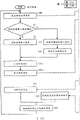
Fig. 4 shows explanation by the process flow diagram of the step of the operational processes of the user terminal 1a-1 execution of the first example embodiment.The user can carry out draw input and/or image-erasing input (seeing Fig. 2) at the drawing screen.For example utilize radio button shown in Figure 2 between drawing input pattern and image-erasing input pattern, to switch the input receiving mode, but be not limited to this.
As shown in Figure 4, when user terminal 1a-1 is received in input under the input receiving mode of drawing (step S1: be), obtain by the stroke of user input and be kept at (step S3) in the middle of the first memory 15a as drawing entering stroke (step S2) and with it, and be plotted in subsequently all strokes (step S4) of preserving among the first memory 15a.
On the one hand, when user terminal 1a-1 receives not under the input receiving mode of drawing but during the input under image-erasing input receiving mode (step S1: no), obtain the stroke of user's input as image-erasing entering stroke (step S5), and obtain subsequently cross-image information (step S6).
Hereinafter, with reference to figure 5 explanation cross-image information.For example, for user terminal 1a-1, drawing input message is determined to be in the cross-image information that whether has any one coordinate of image-erasing entering stroke in the circumscribed rectangular region of a drawing entering stroke.Utilization is specified circumscribed rectangular region about the point of drawing entering stroke.For example, limit as shown in Figure 5 the circumscribed rectangular region of a drawing entering stroke by four angle end points and dot-and-dash line.
In Fig. 5, for example, drawn and had coordinate (x1, y1), (x2, y2), (x3, y3) and (x4, y4) drawing entering stroke A, have the drawing entering stroke B of coordinate (x5, y5) and (x6, y6) and have coordinate (x7, y7), (x8, y8), (x9, y9), (x10, y10) (x11, y11) and the drawing entering stroke of (x12, y12).Because the coordinate (x10 of image-erasing entering stroke, y10) and (x11, y11) be present in the circumscribed rectangular region by the drawing entering stroke A shown in the dot-and-dash line, the entering stroke A that therefore draws is called as the cross-image of intersecting with the image-erasing entering stroke.In Fig. 5, owing to there not being any one coordinate of image-erasing entering stroke in the circumscribed rectangular region of the drawing entering stroke B shown in the dot-and-dash line, the entering stroke B that therefore draws is not called as cross-image.
In the application was open, the information of the drawing entering stroke of intersecting with image-erasing entering stroke information was called as " cross-image information " or " cross-image ".
As shown in Figure 4, user terminal 1a-1 is based on acquisition of information deletion zone (seeing Fig. 3) (step S7) of image-erasing entering stroke.Such deletion zone can generate or set by setting given stroke interval for the image-erasing entering stroke.For example, the stroke interval of image-erasing entering stroke can be set as 10 pixels.For example, when the information of image-erasing entering stroke as shown in Figure 3 comprises coordinate (x5, y5) and when (x6, y6), deletion can be set to four rectangles that point limits by following formula (1), (2), (3) and (4) appointment.
(formula 1)
(x5-asinθ,y5+acosθ) (1)
(x5+asinθ,y5-acosθ) (2)
(x6+asinθ,y6-acosθ) (3)
(x6-asinθ,y6+acosθ) (4)
Wherein, set cos θ=(x6-x5)/r, sin θ=(y6-y5)/r and r=√ are [(x6-x5)
2+ (y6-y5)
2], and for example, a=10 pixel.
Subsequently, in user terminal 1a-1, from storer 15, delete the coordinate (step S8) of the cross-image information that deletion comprises in the zone, and from the image that display unit 12 shows also with its deletion.And then, at step S8, the coordinate that is not included in the deletion zone is kept in the first memory 15.In the application was open, for simple purpose, the term coordinate was used to represent a coordinate or a plurality of coordinate.In the application was open, " coordinate is contained in " or " coordinate is present in " had similar implication.
Explain when when the graphics processing device input picture is deleted entering stroke, utilizing stroke dispenser 51 to cut apart stroke information (or data) with reference to figure 6 and Fig. 7.Fig. 6 shows by the example condition before stroke dispenser 51 split images, and Fig. 7 shows by the example condition after stroke dispenser 51 split images.
At first, suppose that the user has inputted the specific input such as entering stroke, but wherein user's example such as mouse as input receiving element 11.The user-operable mouse input have coordinate (x8, y8), the image-erasing entering stroke of (x9, y9), (x10, y10), (x11, y11), (x12, y12) and (x13, y13).Subsequently, cross-image information acquisition unit 13 is obtained the coordinate of the drawing entering stroke that intersects with the entering stroke of relevant deletion input picture, and the coordinate of drawing entering stroke is kept in the storer 15.For example, in Fig. 6, can obtain have coordinate (x1, y1), the drawing entering stroke 1 of (x2, y2), (x3, y3), (x4, y4) and (x5, y5), and it is kept in the middle of the storer 15.
Subsequently, user terminal 1a-1 obtains the coordinate of the information of image-erasing entering stroke of concern and the drawing entering stroke that intersects such as the image-erasing entering stroke with paying close attention to of the drawing entering stroke 1 of Fig. 6 as " cross-image information " from storer 15, and utilizes the computing method that the following describes to calculate any one coordinate that whether has the drawing entering stroke in the inside in each deletion zone (seeing Fig. 6).User terminal 1a-1 deletes the coordinate that comprises in the deletion zone, and utilize any coordinate that is not included in the deletion zone to generate new coordinate, this deletion zone comprises at least one coordinate and is arranged as list of coordinates with given order, all image informations 3 and 4 as shown in Figure 7.
(calculating of stroke dispenser)
Calculate each deletion intra-zone in the image-erasing entering stroke with reference to figure 6 explanation by stroke dispenser 51 and whether have each coordinate in the cross-image information.
For example, for the image-erasing entering stroke, limit two continuous coordinate points (x8 by four following points, y8) and the deletion of (x9, y9) zone, wherein set cos θ=(x9-x8)/r, sin θ=(y9-y8)/r, r=√ is [(x9-x8)
2+ (y9-y8)
2], and a=10 pixel for example.
(formula 2)
(x8-asinθ,y8+acosθ) (6)
(x8+asinθ,y8-acosθ) (7)
(x9+asinθ,y9-acosθ) (8)
(x9-asinθ,y9+acosθ) (9)
If four formula below any one coordinate (x, y) satisfies determine that then coordinate (x, y) is present in the deletion intra-zone corresponding to two continuous coordinate points (x8, y8) and (x9, y9).
y≥-(x-x8)/d+y8 (9)
y≤-(x-x9)/d+y9 (10)
y≥d(x-(x8+asinθ))+(y8-acosθ) (11)
y≤d(x-(x8-asinθ))+(y8+acosθ) (12)
In above-mentioned formula, d=(y9-y8)/(x9-x8).
For example, carry out above-mentioned calculating for per two continuous coordinate of image-erasing entering stroke.
So, in the first example embodiment, by the information of user input (for example, utilize indicating equipment as the view data of hand-written object input) can be treated to the coordinate data in the user terminal, can suppress thus the decline of picture quality and can delete any part (or any part of deleted image data) of such input message, thereby improve the convenience that the user uses graphics processing device.Owing to can replace with vector data the data bitmap of tradition use, so the present invention can obtain above-mentioned effect.
The second example embodiment: server
[configuration]
Fig. 8 shows the example overall configuration according to the graphics processing system of the second example embodiment.The graphics processing system of Fig. 8 comprises a PC (hereinafter, user terminal 1a-2) and the server 2-1 that interconnects each other via network 3.Compare with the first example embodiment, in the second example embodiment, with the similar ground of the first example embodiment, user terminal 1a-2 can comprise input receiving element 11, display unit 12 and cross-image information acquisition unit 13, and server 2-1 can comprise the stroke dispenser 22 corresponding to the stroke dispenser 51 of the first example embodiment.And then user terminal 1a-2 also can comprise draw processing request generator 52 and storer 15, and server 2-1 also can comprise draw processing request receiving device 26, response maker 23 and storer 24.In the second example embodiment, omitted the explanation about the similar elements shown in the first example embodiment.
So, user terminal 1a-2 comprise input receiving element 11 for the input that receives the user, be used for showing image display unit 12, be used for obtaining the cross-image information acquisition unit 13 of cross-image information and draw and process request generator 52.For example, drawing is processed request generator 52 and can be generated the drawing processing request that comprises entering stroke information and the cross-image information of having obtained.
Processing drawing that request generator 52 generates by the drawing that provides among the user terminal 1a-2 processes request and can comprise such as the current entering stroke information that receives of the coordinate data of entering stroke and the cross-image information of having obtained.Correspondingly, request is processed in the user terminal 1a-2 drawing that can generate for example each input, each stroke or each mouse action (such as the action that makes progress from mouse to the downward action of mouse).And then, draw and process the identifier information that request can comprise server 2-1, such as Hostname or Internet protocol address, for example can be Uniform Resource Identifier (URI), " somewhere " that for example is described below.
Specify such drawing to process request by Uniform Resource Identifier (URI), uniform resource locator (URL) etc.For example, have at server the drawing area that is called as " canvas ", URL is in the situation of " somewhere ", appointed information as follows.
When the input of drawing is input as the drawing entering stroke 1 with (x1, y1) shown in Figure 3 and (x2, y2), specify following form (13).
http://somewhere/canvas?cmd=draw&pos=x1,y1,x2,y2 (13)
When the image-erasing input is input as the image-erasing entering stroke with (x5, y5) and (x6, y6), specify following form (14).
http://somewhere/canvas?cmd=erase&pos1=x1,y1,x2,y2&pos2=x3,y3,x4,y4&pos3=x5,y5,x6,y6 (14)
In Fig. 3, image-erasing entering stroke and two objects with (x5, y5) and (x6, y6) intersect: an object is (x1, y1) to (x2, y2), and another object is that (x3, y3) is to (x4, y4).
For example, server 2-1 can comprise draw processing request receiving device 26, stroke dispenser 22, response maker 23 and storer 24.Draw and process the drawing processing request that request receiving device 26 receives user terminal 1a-2 transmission.Process when asking to comprise the information of image-erasing entering stroke when drawing, stroke dispenser 22 will be divided into a plurality of parts as the cross-image information of drawing entering stroke information, and carry out given deletion action.Response maker 23 generates to draw processes the response message of request.Storer 24 is preserved for example identifier of stroke information and stroke information.
For example, the response message that is generated by the response maker 23 of server 2-1 comprises a plurality of drawing entering stroke information that obtain by stroke information being divided into a plurality of parts.
Form of description/form of draw processing the data that comprise in the response message of request can be the structured format, XML (extend markup language) such as JSON (Java (registered trademark) scripting object note) etc., also can be the destructuring form such as text formatting, but be not limited to this.For example, when using the JSON form, can following form (15) appointed information.
[“cmd”:“draw”,“result”:[[“id”:pos1,“pos”:[[x1,y1],[x2,y2]]],[“id”:pos2,“pos”:[[x3,y3],[x4,y4]]]]] (15)
[operational processes]
Fig. 9 A and Fig. 9 B show explanation by the process flow diagram of the step of the operational processes of the graphics processing system execution of the second example embodiment.In the second example embodiment, omitted the explanation about the similar elements shown in the first example embodiment.The user can carry out draw input and/or image-erasing input at drawing screen (seeing Fig. 2).For example, can utilize radio button shown in Figure 2 etc. between drawing input pattern and image-erasing input pattern, to switch the input receiving mode, but be not limited to this.
Shown in Fig. 9 A, when user terminal 1a-2 is received in input under the input receiving mode of drawing (step S1: be), obtain stroke by user input as drawing entering stroke (step S2), and generate the drawing that comprises that pay close attention to or relevant drawing entering stroke and process request (1) (step S51 among Fig. 9 A).
On the one hand, when user terminal 1a-2 receives not under the input receiving mode of drawing but during the input under image-erasing input receiving mode (step S1: no), obtain stroke by user input as image-erasing entering stroke (the step S31 among Fig. 9 A), the information of the drawing entering stroke that the image-erasing entering stroke of obtaining subsequently and paying close attention to intersects (for example, coordinate data) is as cross-image information (the step S41 among Fig. 9 A).
And then request generator 52 is processed in the drawing of user terminal 1a-2 can generate drawing processing request (2) (the step S51 among Fig. 9 A) that comprises image-erasing entering stroke and cross-image information.User terminal 1a-2 sends the drawing that generates and processes request to server 2-1 (the step S61 among Fig. 9 A).
As mentioned above, drawing is processed request generator 52 and is generated the drawing processing request (1) of the information that comprises the drawing entering stroke or comprise the image-erasing entering stroke and the drawing of cross-image information processing request (2), and will draw and process the graphics processing device of asking to send to such as server 2-1.
Subsequently, server 2-1 receives to draw and processes request (the step S9 among Fig. 9 B).Process the information that request does not comprise the image-erasing entering stroke if draw, process request (1) (step S10 among Fig. 9 B: no) if namely receiving draws, then in such as the first memory of storer 24, preserve faithfully received drawing and process the drawing entering stroke information (the step S14 among Fig. 9 B) that comprises in the request.Subsequently, server 2-1 generates response message (3) (the step S15 among Fig. 9 B) with reference to the content in the first memory, and sends response message (3) (the step S16 among Fig. 9 B) to user terminal 1a-2.Protect stored first memory and can be such as the volatile memory of random access storage device (RAM) or such as the nonvolatile memory of ROM (read-only memory) (ROM).
If server 2-1 receives the drawing of the information that comprises the image-erasing entering stroke and processes request, process request (2) (step S10 among Fig. 9 B: be) if namely receiving draws, then based on the acquisition of information deletion zone (the step S11 among Fig. 9 B) of the image-erasing entering stroke of paying close attention to, wherein obtain the deletion zone by carrying out the processing similar to the first example embodiment.
Subsequently, server 2-1 determines whether to exist each coordinate (the step S12 among Fig. 9 B) of drawing entering stroke in the deletion zone of paying close attention to, and preserves the coordinate (step S13) that does not comprise in the deletion zone in first memory.At step S12, determine for each coordinate of drawing entering stroke whether each coordinate is present in the deletion zone of paying close attention to, and continue so definite processing until checked all coordinates of drawing entering stroke.
When having finished for all coordinates of drawing entering stroke, server 2-1 all carries out (the step S12 among Fig. 9 B: no) when determine processing, server 2-1 generates response message (step S15) with reference to the content in the first memory, and response message is sent to user terminal 1a-2 (the step S16 among Fig. 9 B).
As mentioned above, the response message that is generated by response maker 23 can comprise by stroke information being divided into a plurality of parts obtains a plurality of drawing entering stroke information.
When user terminal 1a-2 had been inputted the image-erasing entering stroke, similar with the processing of the first example embodiment, the stroke dispenser 22 of server 2-1 was cut apart stroke information.
At first, suppose that user terminal 1a-2 sends following drawing and processes request, wherein the user uses mouse as input receiving element 11.For example, user's operating mouse input have coordinate (x8, y8), the image-erasing entering stroke of (x9, y9), (x10, y10), (x11, y11), (x12, y12) and (x13, y13).Subsequently, cross-image information acquisition unit 13 is obtained the coordinate of the drawing entering stroke that the image-erasing entering stroke with correlated inputs intersects, and preserves the drawing entering stroke in storer 15.In Fig. 6, obtain have coordinate (x1, y1), the drawing entering stroke 1 of (x2, y2), (x3, y3), (x4, y4) and (x5, y5) and it is kept in the storer 15.
Subsequently, draw and process request generator 52 is obtained the information of the image-erasing entering stroke of paying close attention to and the drawing entering stroke that intersects with the image-erasing entering stroke of paying close attention to (the drawing entering stroke 1 of Fig. 6) from storer 15 coordinate conduct " cross-image information ", and generate the information comprise the image-erasing entering stroke of paying close attention to and request (2) is processed in the drawing of the coordinate of the drawing entering stroke that intersects with the image-erasing entering stroke of paying close attention to, and will draw to process and ask to send to server 2-1.
Subsequently, ask the server 2-1 of (2) in the drawing processing that receives from user terminal 1a-2 transmission, stroke dispenser 22 utilizes above-mentioned computing method to calculate each coordinate that whether has the cross-image information that comprises in the drawing processing request (2) in regional (the seeing Fig. 6) inside of each deletion.Server 2-1 deletes the coordinate that comprises in the deletion zone, and utilize any coordinate be not included in the deletion zone to generate new stroke, wherein new stroke comprise with all as shown in Figure 7 image information 3 and given tactic at least one coordinate of 4 list of coordinates.
Subsequently, response maker 23 generates and comprises that the new stroke that generated by stroke dispenser 22 (for example, the response message of the drawing entering stroke (image information 2 of Fig. 7) that the image information 3 and 4 of Fig. 7) and does not intersect with cross-image information, and beam back new stroke information (step S71) to user terminal 1a-2.
So, in the second example embodiment, can be used as coordinate data operation or by the information of user's input (for example process, utilize indicating equipment as the view data of hand-written object input), can reduce thus network load and can delete any part (but or any part in the deleted image data) in the input message, thereby improve the convenience that the user uses graphics processing system.
The 3rd example embodiment: graphics processing system
[configuration]
Figure 10 shows the example overall configuration according to the graphics processing system of the 3rd example embodiment.The graphics processing system of Figure 10 comprises at least one, or two and more PC (hereinafter, user terminal 1a-3,1b to 1n) and the server 2-2 that is connected with each other via network 3.Compare with the second example embodiment, in the 3rd example embodiment, user terminal 1a-3 (with user terminal 1b to 1n) can comprise transmission request generator 14.In the 3rd example embodiment, omitted the explanation about the similar elements shown in the second example embodiment.
The transmission request by transmitting request generator 14 generations that provides to user terminal 1a-3 can comprise the current entering stroke information that receives (such as the coordinate data of entering stroke) and the cross-image information of obtaining.Correspondingly, user terminal 1a-2 generates the transmission request of (such as from mouse action downwards to upwards action of mouse) of each input, each stroke or each mouse action.And then, draw and process the identification information that request can comprise server 2-2, such as Hostname or Internet protocol address, for example can be that " somewhere " is set to Uniform Resource Identifier (URI), as described below.
Specify the request of transmission by Uniform Resource Identifier (URI), uniform resource locator (URL) etc.For example, have at server in the situation of URL " somewhere " of the drawing project that is called as " canvas ", as follows appointed information.
When the input of drawing is input as the drawing entering stroke 1 with (x1, y1) shown in Figure 3 and (x2, y2), specify following form (16).
http://somewhere/canvas?cmd=draw&pos=x1,y1,x2,y2 (16)
When the image-erasing input is input as the image-erasing entering stroke with (x5, y5) and (x6, y6), specify following form (17).
http://somewhere/canvas?cmd=erase&pos1=x1,y1,x2,y2&pos2=x3,y3,x4,y4&pos3=x5,y5,x6,y6 (17)
In Fig. 3, image-erasing entering stroke and two objects intersect: an object is (x1, y1) to (x2, y2), and another object is that (x3, y3) is to (x4, y4).
For example, server 2-2 can comprise transmission request receiving device 21, stroke dispenser 22, response maker 23 and storer 24.Transmit request receiving device 21 and receive the transmission request that is sent by user terminal 1a-3.When the request of transmitting comprises the information of image-erasing entering stroke, stroke dispenser 22 will be divided into a plurality of parts as the cross-image information of drawing entering stroke information, and carry out given deletion action.Response maker 23 generates the response message of the request of transmission.
For example, the response message that is generated by the response maker 23 of server 2-2 comprises a plurality of drawing entering stroke information that obtain by stroke information being divided into a plurality of parts.
Form of description/the form of the data that comprise in the response message of the request of transmitting can be the structured format, XML (extend markup language) such as JSON (Java (registered trademark) scripting object note) etc., also can be the destructuring form such as text formatting, but be not limited to this.For example, when using the JSON form, can following form (18) appointed information.
[“cmd”:“draw”,“result”:[[“id”:pos1,“pos”:[[x1,y1],[x2,y2]]],[“id”:pos2,“pos”:[[x3,y3],[x4,y4]]]]] (18)
[operational processes]
Figure 11 A and Figure 11 B show explanation by the process flow diagram of the step of the operational processes of the graphics processing system execution of the 3rd example embodiment.In the 3rd example embodiment, omitted the explanation about the similar elements shown in the second example embodiment.The user can carry out draw input and/or image-erasing input at drawing screen (seeing Fig. 2).For example, can utilize radio button shown in Figure 2 etc. between drawing input pattern and image-erasing input pattern, to switch the input receiving mode, but be not limited to this.
When user terminal 1a-3 is received in input under the input receiving mode of drawing (the step S1 among Figure 11: be), obtain stroke by user input as drawing entering stroke (the step S2 among Figure 11), and generate the transmission request (1) (the step S51a among Figure 11 A) that comprises the drawing entering stroke of paying close attention to.
On the one hand, when user terminal 1a-3 receives not under the input receiving mode of drawing but during the input under image-erasing input receiving mode (the step S1 among Figure 11 A: no), obtain stroke by user input as image-erasing entering stroke (the step S31 among Figure 11 A), the information of the drawing entering stroke that the image-erasing entering stroke of obtaining subsequently and paying close attention to intersects (for example, coordinate data) is as cross-image information (the step S41 among Figure 11 A).
Subsequently, transmit request generator 14 and can generate the information that comprises the image-erasing entering stroke and the transmission request (2) (the step S51a among Figure 11 A) of cross-image information.User terminal 1a-3 sends the drawing that generates and processes request to server 2-2 (the step S61a among Figure 11 A).
As mentioned above, transmit the transmission request (2) that request generator 14 generates the transmission request (1) of the information that comprises the drawing entering stroke or comprises information and the cross-image information of image-erasing entering stroke, and the request of will transmitting sends to server 2-2.
Subsequently, server 2-2 receives the request of transmitting (the step S9a among Figure 11 B).If the request of transmission does not comprise the information of image-erasing entering stroke, transmit request (1) (step S10 among Figure 11 B: no) if namely receive, then in storer 24 or first memory 24a, preserve faithfully received drawing and process the drawing entering stroke information (the step S14 among Figure 11 B) that comprises in the request.
Subsequently, the content among server 2-2 reference memory 24 or the first memory 24a generates response message (3) (the step S15 among Figure 11 B), and sends response message (3) (the step S16 among Figure 11 B) to user terminal 1a-3.Storer 24 can comprise such as the volatile memory of random access storage device (RAM) or such as the first memory of the nonvolatile memory of ROM (read-only memory) (ROM).
If server 2-2 receives the transmission request of the information that comprises the image-erasing entering stroke, transmit request (2) (step S10 among Figure 11 B: be) if namely receive, then based on acquisition of information deletion zone (seeing the example of Fig. 3) (step S11 among Figure 11 B) of the image-erasing entering stroke of paying close attention to, wherein obtain the deletion zone by carrying out the processing similar to the first example embodiment.
Subsequently, server 2-1 determines whether to exist each coordinate (the step S12 among Figure 11 B) of drawing entering stroke in the deletion zone of paying close attention to, and preserves the coordinate (the step S13 among Figure 11 B) that does not comprise in the deletion zone in first memory.At step S12, determine for each coordinate of drawing entering stroke whether each coordinate is present in the deletion zone of paying close attention to, and continue so definite processing until checked all coordinates of drawing entering stroke.
When having finished for all coordinates of drawing entering stroke, server 2-2 all carries out (the step S12 among Figure 11 B: no) when determine processing, server 2-2 generates response message (step S15) with reference to the content in the first memory, and response message is sent to user terminal 1a-2 (step S16).As mentioned above, the response message that is generated by response maker 23 can comprise by stroke information being divided into a plurality of parts obtains a plurality of drawing entering stroke information.
When user terminal 1a-3 had been inputted the image-erasing entering stroke, similar with the processing of the first example embodiment, the stroke dispenser 22 of server 2-2 was cut apart stroke information.
With reference to figure 12A and Figure 12 B the information of being shared by user terminal is described, is wherein shared from the drawing entering stroke information of each user terminal input by other user terminal.In Figure 12 A and Figure 12 B, specified identical step number to processing with the same operation shown in Figure 11 A and Figure 11 B, and omitted the explanation for these steps.
The below carries out the information sharing between the user terminal.Before receiving input message (that is, when just beginning), such as each user terminal of 1a-3 and 1b to 1n the information sharing request is sent to server 2-2 (the step S00 of Figure 12 A).When server 2-2 receives the information sharing request (the step S100 among Figure 12 B), server 2-2 refusal response message sharing request.Subsequently, after the response message that has sent server 2-2 (the step S16 among Figure 12 B), server 2-2 sends the response (step S19, S20) of information sharing request to each user terminal, and this is unaccepted as mentioned above.And then, if do not carry out the input of drawing for user terminal 1a-3, user terminal 1a-3 only sends information sharing request (S00 among Figure 12 A) and receives the response (S90) of information sharing request, can share drawing entering stroke information thus in the middle of other user terminal 1b to 1n and user terminal 1a-3.
So, in the 3rd example embodiment, can be used as coordinate data operation or by the information of user's input (for example process, utilize indicating equipment as the view data of hand-written object input), can reduce thus because the network load that the information of sharing causes, suppress the picture quality variation, and can delete any part (but or any part in the deleted image data) in the input message, thereby improved the convenience that the user uses graphics processing system.
The 4th example embodiment: the user terminal of Negotiation speed deletion
[configuration]
Figure 13 shows the example overall configuration according to the user terminal of the 4th example embodiment.Compare with the first example embodiment, the user terminal of the 4th example embodiment can comprise stroke dispenser 51, translational speed computing unit 54 and delete regional generation unit 55.The translational speed of translational speed computing unit 54 computed image deletion entering stroke.Delete regional generation unit 55 based on the translational speed generation deletion zone of image-erasing entering stroke.The coordinate of the drawing entering stroke that comprises in the deletion zone that stroke dispenser 51 deletion generates is wherein cut apart in the deletion zone and is deleted stroke.In the 4th example embodiment, omitted the explanation about the similar elements shown in the first example embodiment.
In the 4th example embodiment, the translational speed of image-erasing entering stroke determines because the size in deletion zone is based on, and therefore only can delete many image objects by an input operation of image-erasing entering stroke.In traditional configuration, when carrying out deletion work, the user needs actions menu to change the width of deletion interimly, but in the present invention, the user need not to operate such menu, can delete many image objects by the image-erasing entering stroke that input has a fast speed.
[operational processes]
Figure 14 shows explanation by the process flow diagram of the step of the operational processes of the graphics processing device execution of the 4th example embodiment.In Figure 14, provided identical step number for the identical operational processes shown in the first example embodiment, and omitted the explanation for these processing.
In the 4th example embodiment, when user terminal 1a-1 receives not under the input receiving mode of drawing but during the input under image-erasing input receiving mode (the step S1 among Figure 14: no), user terminal 1a-4 obtains the entering stroke that receives as image-erasing entering stroke (the step S5 among Figure 14).
When user terminal 1a-4 received the input of image-erasing entering stroke, cross-image information acquisition unit 13 was obtained the coordinate data of the drawing entering stroke that intersects with the image-erasing entering stroke of paying close attention to as cross-image information (the step S6 among Figure 14).And then, translational speed computing unit 54 is based on (for example inputting the start time, mouse is (mouse-down timing) downwards regularly) to the end of input time (for example, mouse is (mouse-up timing) upwards regularly) between the translational speed (the step S66 among Figure 14) of the image-erasing entering stroke paid close attention to of distance (measuring with the pixel) calculating of elapsed time (for example, with metering second) and image-erasing entering stroke.Subsequently, delete regional generation unit 55 and obtain deletion zone (the step S7 among Figure 14) based on information and the translational speed of image-erasing entering stroke.
Figure 15 shows the difference in size according to the deletion zone of the 4th example embodiment.When deletion zone is the rectangle that is for example limited by four angle end points, deletes regional generation unit 55 and can determine to delete regional size based on the translational speed of image-erasing entering stroke.For example, Figure 15 shows deletion zone 1 and the deletion zone 2 in the deletion zone with different sizes, and wherein the translational speed of the image-erasing entering stroke in deletion zone 2 is faster than the translational speed of the image-erasing entering stroke in deletion zone 1.
Consider the convenience that the user operates, the zone can be limited threshold value " a " and be set as " a=0.75v[pixel] ", wherein " v " is the translational speed of obtaining, such as 1000 pixel/seconds, and 0.75 be the coefficient that represents in response to the order of magnitude in the deletion zone of translational speed, and coefficient is larger, and the size in deletion zone is just larger.Coefficient is not limited to 0.75.
Subsequently, in first memory 15a, preserve the coordinate (the step S8 among Figure 14) that does not comprise in the deletion zone.Step subsequently is similar to Fig. 4, therefore no longer it is given unnecessary details.
As mentioned above, in the 4th example embodiment, the translational speed of image-erasing entering stroke generates because deletion zone is based on, and therefore can seamlessly carry out the switching in deletion zone.This more seamless operation means from for example automatically changing the deletion width by the regional predetermined deletion width of the predefined deletion of user.Concrete, when the translational speed of image-erasing entering stroke is set to when very fast, can increase the deletion width; Opposite, when the translational speed of image-erasing entering stroke is set to when slower, can reduce to delete width.And then, after carrying out deletion action, can automatically the deletion width of deleting the zone be turned back to predetermined deletion width.Utilize such configuration, when each execution deletion work, the user need not the menu of operation with traditional and selects to delete regional size, designs thus efficient operation.
The 5th example embodiment: by the deletion of length
[configuration]
Figure 16 shows the example overall configuration according to the graphics processing device of the 5th example embodiment.For example, compare with the 4th example embodiment, the user terminal 1a-5 of the 5th example embodiment can comprise movable length computing unit 56 and the regional generation unit 55 of deletion.The movable length of movable length computing unit 56 computed image deletion entering stroke, and delete regional generation unit 55 based on the movable length generation deletion zone of image-erasing entering stroke.In the 5th example embodiment, omitted the explanation about the similar elements shown in the 4th example embodiment.
So, in the 5th example embodiment, the movable length of image-erasing entering stroke determines because the size in deletion zone is based on, and therefore only can delete many image objects by an input operation of image-erasing entering stroke.Utilize such configuration, when each execution deletion work, the menu that the user need not operation with traditional comes the size in interim selection deletion zone, can delete many image objects by the image-erasing entering stroke that input has a longer movable length.
[operational processes]
Figure 17 shows explanation by the process flow diagram of the step of the operational processes of the graphics processing device execution of the 5th example embodiment.In Figure 17, for having provided identical step number with the identical operational processes shown in the 4th example embodiment, and omitted the explanation for these processing.
In the 5th example embodiment, user terminal 1a-5 receives the input of image-erasing entering stroke, and cross-image information acquisition unit 13 is obtained the coordinate data of the drawing entering stroke that intersects with the image-erasing entering stroke of paying close attention to as study course image information (the step S6 among Figure 17).And then, movable length computing unit 56 is based on (for example inputting the start time, the downward timing of mouse) calculates the displacement (the step S66a among Figure 17) of the image-erasing entering stroke of being paid close attention to the distance (for example, with the pixel metering) of the image-erasing entering stroke between the end of input time (mouse upwards regularly).Subsequently, delete regional generation unit 55 and obtain deletion zone (the step S7 among Figure 17) based on the information of image-erasing entering stroke and movable length.
Consider the convenience that the user operates, the zone can be limited threshold value " a " and be set as " a=0.75L[pixel] ", wherein " L " is the movable length that obtains, such as the 1000[pixel], and 0.75 be the coefficient that represents in response to the order of magnitude in the deletion zone of movable length, and coefficient is larger, and the size in deletion zone is just larger.Coefficient is not limited to 0.75.
Subsequently, in the first memory 15a of user terminal 1a-5, preserve the coordinate (the step S8 among Figure 17) that does not comprise in the deletion zone.Step subsequently is similar to Fig. 4, therefore no longer it is given unnecessary details.
As mentioned above, in the 5th example embodiment, the regional movable length that is based on the image-erasing entering stroke of deletion generates, but therefore the switching of deleting the zone is carried out on pattern ground.The operation of this non-mode means from for example automatically changing the deletion width by the regional predetermined deletion width of the predefined deletion of user.Concrete, when the movable length of image-erasing entering stroke is set to when longer, can increase the deletion width; Opposite, when the movable length of image-erasing entering stroke is set to more in short-term, can reduce to delete width.And then, after carrying out deletion action, can automatically the deletion width of deleting the zone be turned back to predetermined deletion width.Utilize such configuration, when each execution deletion work, the user need not the menu of operation with traditional and selects to delete regional size, designs thus efficient operation.
The 6th example embodiment: by the deletion of shape
[configuration]
Figure 18 shows the example overall configuration according to the graphics processing system of the 6th example embodiment.For example, compare with the 4th and the 5th example embodiment, the user terminal 1a-6 of the 6th example embodiment can comprise the closed loop computing unit 59 that whether has formed closed loop for computed image deletion entering stroke.When any one coordinate of image-erasing entering stroke formation closed loop and formation drawing entering stroke is present in closed loop inside, stroke dispenser 51 can be deleted all coordinates that consist of the drawing entering stroke, can delete thus whole drawing entering stroke (or whole object).And then, when the image-erasing entering stroke does not consist of closed loop (, the closed loop of part), obtain the deletion zone similar to the aforementioned embodimently, and delete the drawing entering stroke (being called the part delet method) that comprises in the closed loop inside of part.In the 6th example embodiment, omitted the explanation about the similar elements shown in the 4th and the 5th example embodiment.
Figure 19 shows explanation by the process flow diagram of the step of the operational processes of the graphics processing device execution of the 6th example embodiment.In Figure 19, for having provided identical step number with the identical operational processes shown in Figure 17 of the 4th example embodiment, and omitted the explanation for these processing.
In the 6th example embodiment, when user terminal 1a-6 receives the image-erasing entering stroke (the step S1 among Figure 19: no), closed loop computing unit 59 determines whether the image-erasing entering stroke consists of closed loop (the step S300 among Figure 19).
When any one coordinate that has consisted of closed loop and consisted of the drawing entering stroke when the image-erasing entering stroke was present in the inside of closed loop, user terminal 1a-6 deletion consisted of all coordinates (the step S310 among Figure 19) of drawing entering stroke.
Determine that by the closed loop computing unit 59 of user terminal 1a-6 the image-erasing entering stroke is the scheme of closed loop with reference to Figure 20 explanation.For example, closed loop computing unit 59 determines that as follows the image-erasing entering stroke is closed loop.Under the situation of Figure 20, inputted and had coordinate (x1, y1), (x2, y2), the image information of (x3, y3) and (x4, y4) and have a coordinate (x5, y5) and the image information 2 of (x6, y6), also inputted and had coordinate (x7, y7), (x8, y8), (x9, y9), (x10, y10), (x11, y11), (x12, y12), (x13, y13) and the image-erasing entering stroke of (x14, y14).When having inputted such image-erasing entering stroke, coordinate (x7, y7) be (for example to input the start time, the downward timing of mouse) coordinate of input, and coordinate (x14, y14) be (for example to begin the time in end of input, mouse is up and down regularly) coordinate of input, and input middle coordinate (x8, y8), (x9, y9), (x10 between the time in input start time and end of input, y10), (x11, y11), (x12, y12) and (x13, y13).When following condition (19) and (20) when all satisfying, the loop wire with above-mentioned these coordinates is confirmed as closed loop.
(formula 3)
√[xmax-xmin]
2+(ymax-ymin)
2]>Ft (19)
Xmax:x7, x8, x9, x10, x11, x12, x13, the maximal value of x14
Xmin:x7, x8, x9, x10, x11, x12, x13, the minimum value of x14
Ymax:y7, y8, y9, y10, y11, y12, y13, the maximal value of y14
Ymin:y7, y8, y9, y10, y11, y12, y13, the minimum value of y14
Ft=50pixel
√[x14-x7]
2+(y14-y7)
2]<Lt (20)
(the threshold value of closed loop: the Lt=20 pixel)
In the 6th example embodiment, when the image-erasing entering stroke is closed loop and any one coordinate that consists of the drawing entering stroke when being present in the inside of closed loop, 51 deletions of stroke dispenser consist of all coordinates of drawing entering strokes.And then, as shown in figure 21, in the time of within any one coordinate that consists of the drawing entering stroke is present in by the deletion zone of closed loop appointment, 51 deletions of stroke dispenser consist of the coordinate of drawing entering stroke, wherein can delete the part or the whole drawing stroke that are present in the closed loop outside, further improve thus the convenience that the user uses.
As mentioned above, in the 6th example embodiment, whether be closed loop by determining stroke information, but non-mode ground the part of object delete and the complete deletion of object between switch.Utilize above-mentioned configuration, when each execution deletion work, the menu that the user need not operation with traditional comes the part deletion of alternative and the complete deletion of object, designs thus efficient operation.
The 7th example embodiment: will deleted part painted
[configuration]
Compare with the first example embodiment, in the 7th example embodiment, for example by setting different colors, can will deleted part differently show with drawing entering stroke and image-erasing entering stroke the coordinate of cross-image information.In the 7th example embodiment, omitted the explanation with the similar elements shown in the first example embodiment.
As shown in figure 22, in the 7th example embodiment, for example, with solid line (for example, black line on the true screen) shows the drawing entering stroke, show the image-erasing input with fine rule (for example, the red line on the true screen), and with dot-and-dash line (for example, the gray line on the true screen) show will be deleted part.So, change the display type of object that will be deleted by the type that changes color and/or line, thus the user can confirm at last will be deleted that part, carry out mouse upwards delete subsequently after the action will be deleted part.Like this will deleted part be the intersect each other part of fork of image-erasing input line and drawing input line.The number of different colours (such as red, blue etc.) can be set to required any number.
[operational processes]
Figure 23 shows the process flow diagram of the step of the operational processes of being carried out by the user terminal of the 7th example embodiment.In Figure 23, for having provided identical step number with the identical operational processes shown in the first example embodiment of Fig. 4, and omitted the explanation for these processing.
When user terminal receives input under image-erasing input receiving mode (the step S1 among Figure 23: no), obtain stroke by user input as image-erasing entering stroke (the step S5 among Figure 23), and obtain cross-image information (the step S6 among Figure 23).User terminal is deleted zone (the step S7 among Figure 23) based on the acquisition of information of image-erasing entering stroke, and utilizes given color to be presented at the stroke (such as coordinate and line) (the step S400 among Figure 23) that comprises in the deletion zone.User terminal determines whether to have confirmed deletion action subsequently, such as whether having made upwards action (the step S410 among Figure 23) of mouse.Confirm action if carried out deletion, then from first memory 15a, delete the coordinate (the step S8 among Figure 23) that comprises in deleting in the zone, and draw new stroke (the step S4 among Figure 23).If there is not coordinate in the deletion zone, then not execution action and end process.
As mentioned above, in the 7th example embodiment, by to will be deleted the different forms of settings such as color, line of stroke part will partly differently show with drawing entering stroke and image-erasing entering stroke by deleted stroke, the user can confirm that part of stroke that will be deleted easily before making deletion thus, prevent thus faulty operation, such as the part of deletion error.
The 8th example embodiment: stroke recovers action
[configuration]
Figure 25 shows the configured in one piece according to the graphics processing device of the 8th example embodiment.Compare with the first example embodiment, also comprise for recovering or cancelling operation by the stroke recovery unit 58 of the coordinate of image-erasing input deletion.In the 8th example embodiment, omitted the explanation with the similar elements shown in the first example embodiment.First memory 15a can be LIFO (last in, first out) storer that keeps latest data for interim, and such as the data before carrying out deletion action, wherein the up-to-date data that write can take the lead in being read out.Stroke recovery unit 58 can be by to as shown in figure 27 " recover (or returning) " button press, touch or provide instruction and be activated.
[operational processes]
Figure 26 shows the process flow diagram of the step of the operational processes of being carried out by the user terminal of the 8th example embodiment.In the 8th example embodiment, omitted the explanation with the similar elements shown in the first example embodiment.
User terminal 1a-7 determines whether the user operates is that stroke recovers action (the step S120 among Figure 26) in the 8th example embodiment.Recover action (step S120: be) if made stroke, then user terminal 1a-7 obtains up-to-date cross-image information (the step S121 Figure 26: be) from storer 15 or the first memory 15a that is used as stacked memory, and draws the stroke (the step S4 among Figure 26) that is resumed.If not making stroke recovers action (the step S120 among Figure 26: no) and has used image-erasing input receiving mode (the step S1 among Figure 26: no), then obtain stroke by user input as image-erasing entering stroke (the step S5 among Figure 26), and obtain cross-image information (the step S6 among Figure 26).In being used as the first memory 15a of stacked memory, preserve subsequently cross-image information (the step S500 among Figure 26).User terminal 1a-7 obtains deletion zone (the step S7 among Figure 26) based on entering stroke information, from first memory 15a, delete the coordinate that comprises in the deletion zone and the coordinate (the step S8 among Figure 26) that in the deletion zone, does not comprise to first memory 15a preservation, and draw new stroke (the step S4 among Figure 26).
As mentioned above, in the 8th example embodiment, the deleted stroke of operation can be recovered or cancel, operation can be recovered easily or cancel thus because the stroke of maloperation deletion.
The 9th example embodiment: the operation of the server of Negotiation speed deletion
[configuration]
Figure 28 shows the example overall configuration according to the graphics processing system of the 9th example embodiment.Compare with the second example embodiment, in the graphics processing system according to the 9th example embodiment, server 2-3 can comprise based on the translational speed of image-erasing entering stroke and generate the deletion zone generation unit 55 in deletion zone and be used for the coordinate dispenser 22 of the coordinate of the drawing entering stroke that deletion comprises in the deletion zone that generates, and wherein stroke dispenser 22 can be used for cutting apart and deleting stroke.In the 9th example embodiment, omitted the explanation about the similar elements shown in the second example embodiment.
So, in the 9th example embodiment, the translational speed of image-erasing entering stroke determines because the size in deletion zone is based on, and therefore only can delete many image objects by an input operation of image-erasing entering stroke.Utilize above-mentioned configuration, when each execution deletion work, the menu that the user need not operation with traditional to select to delete the size in zone interimly, and deletes many image objects by input picture deletion input more rapidly.
[operational processes]
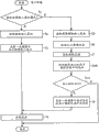
Figure 29 A and Figure 29 B show explanation by the process flow diagram of the step of the operational processes of the graphics processing system execution of the 9th example embodiment.In Figure 29 A and Figure 29 B, provided identical step number for the identical operational processes shown in the second example embodiment of Fig. 9 A and Fig. 9 B, and omitted the explanation for these processing.
In the graphics processing system of the 9th example embodiment, when user terminal 1a-8 receives not under the input receiving mode of drawing but during the input under image-erasing input receiving mode (step S1: no), obtain stroke by user's input as image-erasing entering stroke (the step S31 among Figure 29 A).
In graphics processing system, when receiving the input of image-erasing entering stroke, cross-image information acquisition unit 13 is obtained the coordinate data of the drawing entering stroke that intersects with the image-erasing entering stroke of paying close attention to as cross-image information (the step S41 among Figure 29 A).And then, translational speed computing unit 54 is based on (for example inputting the start time, the downward timing of mouse) to the end of input time (for example, mouse is upwards regularly) between the translational speed (the step S66 among Figure 29 A) of the image-erasing entering stroke paid close attention to of distance (measuring with the pixel) calculating of elapsed time (for example, with metering second) and image-erasing entering stroke.
The cross-image information of being obtained by cross-image information acquisition unit 13 and all be stored in the middle of the storer 15 by the translational speed that translational speed computing unit 54 calculates.
Subsequently, draw and process request generator 52 from storer 15 extraction (or fetching) all image-erasing and drawing entering stroke, cross-image information and translational speeds, process request (the step S51 among Figure 29 A) in order to generate to draw.
Now explanation receives the operational processes of the server 2-3 of the processing request of drawing from user terminal 1a-8.Server 2-3 receives to draw and processes request (the step S9 among Figure 29 B).Comprise image-erasing entering stroke (the step S10 among Figure 29 B: be) if request is processed in the drawing that receives, delete regional generation unit 55 and obtain deletion zone (the step S11 among Figure 29 B) based on the information of the image-erasing entering stroke that comprises in the processing request of drawing and the translational speed of image-erasing entering stroke.Carry out the processing that generates the deletion zone with the 4th example embodiment similarly, therefore no longer the generation of deleting the zone is processed describing.
Subsequently, server 2-3 determines whether each coordinate of drawing entering stroke is present in (the step S12 among Figure 29 B) in the deletion zone of paying close attention to, and preserves the coordinate (the step S13 among Figure 29 B) that is not included in the deletion zone to first memory.In step S12, determine for each coordinate of drawing entering stroke whether each coordinate is present in the deletion zone of paying close attention to, and repeat definite the processing until all coordinates of drawing entering stroke are all checked.Server 2-3 preserves the coordinate (the step S13 among Figure 29 B) that is not included in the deletion zone to the storer 24 that comprises first memory.Step subsequently is similar to Fig. 9, therefore it is repeated no more.
As mentioned above, in the 9th example embodiment, the translational speed of image-erasing input determines because the size in deletion zone is based on, and therefore seamlessly (modelessly) carries out the switching in deletion zone.Utilize above-mentioned configuration, when each execution deletion work, the user need not the menu of operation with traditional and selects to delete regional size, designs thus efficient operation.
The tenth example embodiment: by the deletion of length
[configuration]
Figure 30 shows the example overall configuration according to the graphics processing system of the tenth example embodiment.For example, compare with the 9th example embodiment, in the graphics processing system according to the tenth example embodiment, server 2-4 can comprise that the movable length based on the image-erasing entering stroke generates the deletion zone generation unit 55 in deletion zone.In the tenth example embodiment, omitted the explanation about the similar elements shown in the 9th example embodiment.
So, in the tenth example embodiment, the movable length of image-erasing entering stroke determines because the size in deletion zone is based on, and therefore only can delete many image objects by an input operation of image-erasing entering stroke.Utilize such configuration, when each execution deletion work, the menu that the user need not operation with traditional comes the size in interim selection deletion zone, can delete many image objects by the image-erasing entering stroke that input has a longer movable length.
[operational processes]
Figure 31 A and Figure 31 B show explanation by the process flow diagram of the step of the operational processes of the graphics processing system execution of the tenth example embodiment.In Figure 31 A and Figure 31 B, provided identical step number for the identical operational processes shown in the 9th example embodiment of Figure 29 A and Figure 29 B, and omitted the explanation for these processing.
In the tenth example embodiment, when user terminal 1a-9 received the input of image-erasing entering stroke, cross-image information acquisition unit 13 was obtained the coordinate data of the drawing entering stroke that intersects with the image-erasing entering stroke of paying close attention to as cross-image information (the step S41 among Figure 31 A).And then, movable length computing unit 56 is based on (for example inputting the start time, the downward timing of mouse) to the end of input time (for example, mouse is upwards regularly) between distance (for example, with pixel metering) the calculating movable length (the step S66a among Figure 31 A) of image-erasing entering stroke.
The cross-image information of being obtained by cross-image information acquisition unit 13 and all be stored in the middle of the storer 15 by the movable length that movable length computing unit 56 calculates.
Subsequently, draw and process request generator 52 from storer 15 extraction (or fetching) all image-erasing and drawing entering stroke, cross-image information and movable lengths, process request (the step S51 among Figure 31 A) in order to generate to draw.
Now explanation receives the operational processes of the server 2-4 of the processing request of drawing from user terminal 1a-9.Server 2-4 receives to draw and processes request (the step S9 among Figure 31 B).Comprise image-erasing entering stroke (the step S10 among Figure 31 B: be) if request is processed in the drawing that receives, delete regional generation unit 55 and obtain deletion zone (the step S11 among Figure 31 B) based on the information of the image-erasing entering stroke that comprises in the processing request of drawing and the movable length of image-erasing entering stroke.Carry out the processing that generates the deletion zone with the 4th example embodiment similarly, therefore no longer the generation of deleting the zone is processed describing.
Subsequently, server 2-4 determines whether each coordinate of drawing entering stroke is present in (the step S12 among Figure 31 B) in the deletion zone of paying close attention to, and preserves the coordinate (the step S13 among Figure 31 B) that is not included in the deletion zone to first memory.In step S12, determine for each coordinate of drawing entering stroke whether each coordinate is present in the deletion zone of paying close attention to, and repeat definite the processing until all coordinates of drawing entering stroke are all checked.Server 2-4 preserves the coordinate (the step S13 among Figure 31 B) that is not included in the deletion zone to the storer 24 that comprises first memory.Step subsequently is similar to Figure 29 A and Figure 29 B, therefore it is repeated no more.
As mentioned above, in the tenth example embodiment, the movable length of image-erasing input determines because the size in deletion zone is based on, but therefore the regional switching of deletion is carried out on non-mode ground.Utilize above-mentioned configuration, when each execution deletion work, the user need not the menu of operation with traditional and selects to delete regional size, designs thus efficient operation.
The 11 example embodiment: by the deletion of shape
[configuration]
Figure 32 shows the example overall configuration according to the graphics processing system of the 11 example embodiment.For example, compare with the 9th and the tenth example embodiment, in the 11 example embodiment, user terminal 1a-10 can comprise the closed loop computing unit 59 that whether has consisted of closed loop for definite image-erasing entering stroke, and server 2-5 can comprise be used to the stroke dispenser 22 of cutting apart stroke.When the image-erasing entering stroke is that closed loop and any one coordinate that consists of the drawing entering stroke are present in closed loop when inner, 22 deletions of stroke dispenser consist of all coordinates of drawing entering strokes, delete thus whole drawing entering stroke (or whole object).And then, when the image-erasing entering stroke is not closed loop (, part closed loop), obtain the deletion zone with the mode that is similar to above-described embodiment, and the coordinate of the drawing entering stroke that comprises of deletion closed loop inside.In the 11 example embodiment, omitted the explanation about the similar elements shown in the first example embodiment.
Figure 33 A and Figure 33 B show explanation by the process flow diagram of the step of the operational processes of the graphics processing device execution of the 11 example embodiment.In Figure 33 A and Figure 33 B, for having provided identical step number with Figure 29 A/29B of the tenth example embodiment with the identical operational processes shown in Figure 31 A/31B with reference to the 9th, and omitted the explanation for these processing.
In the 11 example embodiment, when receiving the image-erasing entering stroke, closed loop computing unit 59 determines whether the image-erasing entering stroke is stroke (the step S300 among Figure 33 A).
In first memory 15a, preserve the result who whether forms closed loop.When the image-erasing entering stroke is not closed loop, in first memory 15a, preserve the cross-image information of being obtained by cross-image information acquisition unit 13.Subsequently, the processing request generator 52 of drawing is extracted (or fetching) all image-erasings and definite result of drawing entering stroke, cross-image information and closed loop from storer 15, asks (the step S51 among Figure 33 A) in order to generate to draw to process.Can carry out the processing of being carried out by closed loop computing unit 59 with the 6th example embodiment similarly, therefore no longer it be given unnecessary details.
Now explanation receives the operational processes of the server 2-5 of the processing request of drawing from user terminal 1a-10.Server 2-5 receives to draw and processes request (the step S9 among Figure 33 B).Received drawing is processed request and is comprised image-erasing entering stroke (the step S10 among Figure 33 B: be), and this is confirmed as closed loop in step S300.When any one coordinate that has formed closed loop and consisted of the drawing entering stroke when the image-erasing entering stroke was present in the inside of image-erasing entering stroke, deletion consisted of all coordinates of the drawing entering stroke of paying close attention to.In this case, response message is based on (the step S15 among Figure 33 B) that the identifier as the drawing entering stroke of paying close attention to of drawing entering stroke that will be deleted generates, and response message is sent to user terminal 1a-10 (the step S16 among Figure 33 B).
When will delete the stroke of being identified by pos1 and pos2 by deletion action the time, for example can be by the JSON form specified response information shown in (21).
[“cmd”:“erase”,“id”:[pos1,pos2]] (21)
As mentioned above, in the 11 example embodiment, whether be closed loop by determining stroke information, but the switching between the integral body deletion of the part deletion of object and object of non-mode ground.Utilize above-mentioned configuration, when each execution deletion work, the menu that the user need not operation with traditional comes the part deletion of alternative and the integral body deletion of object, designs thus efficient operation.
The 12 example embodiment: stroke recovers action
[configuration]
Figure 34 shows the configured in one piece according to the graphics processing device of the 12 example embodiment.Compare with the 8th example embodiment, server 2-6 comprises the stroke recovery unit 58 that recovers the coordinate deleted by the image-erasing input.In the 12 example embodiment, omitted the explanation with the similar elements shown in the 8th example embodiment.When pressing " recovery " button (seeing Figure 27), user terminal 1a-10 sends the drawing that for example has following form (22) and processes request.
http://somewhere/canvas?cmd=undo (22)
Shown in Figure 35 A and Figure 35 B, when receiving drawing processing request, server 2-6 obtains up-to-date cross-image information from the first memory 15a that is used as stacked memory, and generates the response message that comprises cross-image information.For example with the response format of the JSON form appointment shown in following (23), wherein hypothesis has the cross-image information pos1 of (x1, y1) and (x2, y2) and has (x3, y3) and the cross-image information pos2 of (x4, y4) be up-to-date deletion information.
[“cmd”:“undo”,“result”:[[“id”:pos1,“pos”:[[x1,y1],[x2,y2]]],[“id”:pos2,“pos”:[[x3,y3],[x4,y4]]]]] (23)
Shown in Figure 35 A and Figure 35 B, if receiving to draw, server 2-6 do not process request, then user terminal 1a-10 determines to exist the image-erasing input.If the image-erasing input exists, then preserving in being used as the first memory 15a of stacked memory draws processes the cross-image information that comprises in the request.Step subsequently is similar to the 11 example embodiment, therefore no longer it is given unnecessary details.
As mentioned above, in the 12 example embodiment, can recover deleted stroke, recover easily because the stroke that maloperation is deleted thus.
[hardware configuration]
The user terminal 1 that now explanation is used in above-mentioned example embodiment and the hardware configuration of server 2.
As shown in figure 36, user terminal 1 can be signal conditioning package 100, by signal conditioning package 100, each participant of meeting can with reference to, the input or edit file, and signal conditioning package 100 can be desktop PC, notebook-sized personal computer, such as the portable information terminal equipment of personal digital assistant (PDA) and such as electron plates such as blanks, but be not limited to this, demand of considering the user etc. can change the size of signal conditioning package 100.Hereinafter, the exemplary hardware configuration of user terminal 1 (for example, notebook-sized personal computer) is described with reference to Figure 36, Figure 36 shows the example block diagram of the unit that is electrically connected in signal conditioning package 100.So, Figure 36 shows the exemplary hardware configuration of the signal conditioning package 100 (such as user terminal 1) that uses as example embodiment.
As shown in figure 36, signal conditioning package 100 (as user terminal 1) can be computer system, it comprises CPU (central processing unit) (CPU) 101, ROM (read-only memory) (ROM) 102 and random access storage device (RAM) 103, CPU 101 control system on the whole wherein, ROM 102 preserves active program etc., and RAM 103 is used as the working storage territory of CPU 101.Signal conditioning package 100 further comprises keyboard 104, indicating equipment 105, hard disk 106, display 107, network interface (I/F) 108 and bus 109.Keyboard 104 is used for input text, character, numeral, instruction etc., and display 107 is such as display devices such as LCD (liquid crystal display), and network I/F 108 is used for interconnection network 3, and bus 109 is used for the said units of link information treating apparatus 100.
Indicating equipment 105 is mouse, touch pad, trace ball etc. typically, and it is used for mobile cursor, selects the zone, but is not limited to this.In the present invention, indicating equipment 105 can be used as the message unit of input message, also can be used as the unit of detection coordinates.
For example, the indicating equipment such as mouse can be used as coordinate detector.For example, when equipment was used to the input operation event, " mouse button is downward " action was corresponding to the input beginning, and " mouse button upwards ", action was corresponding to end of input, and " mouse button moves down " action continues mobile (that is, just in entering stroke) corresponding to input.
The information input unit for detection of coordinate like this can be mouse, but is not limited to this.For example, such information input unit can be pointer or indicating equipments such as finger tip, pen, can point to thus and the detection coordinates surveyed area in coordinate position.And then information input unit can be input information/output unit, and such as the touch pad type, it can integrally be placed on the demonstration side of the display screen that is used as display unit.In such input information/output unit, a face not only can be used for showing (or output) but also can be used for writing (or input) information.
The coordinate measurement that can carry out by some known methods is such as light shield (light shield) method (seeing JP-2000-105671-A) etc.; Light reflecting method detects such sensing position thereby wherein inserted pointer with the luminous flux in the reflection coordinate measurement zone; The camera method for catching, the pointer that is wherein caught in the coordinate measurement zone by camera points to the position to detect; Light emitting diode (LED) array approach; Ultrasonic elastic wave method; Simulation capacitive coupling method; Pressure-sensing method etc.
As shown in figure 37, signal conditioning package 200 (as server 2) can be computer system, it comprises CPU (central processing unit) (CPU) 201, ROM (read-only memory) (ROM) 202 and random access storage device (RAM) 203, CPU 201 control system on the whole wherein, ROM 202 preserves active program etc., and RAM 203 is used as the working storage territory of CPU 201.Signal conditioning package 200 further comprises keyboard 204, mouse 205, hard disk 206, display 207, network interface (I/F) 208 and bus 209.Keyboard 204 is used for input text, character, numeral, instruction etc., and display 207 is such as display devices such as LCD (liquid crystal display), and network I/F 208 is used for interconnection network 3, and bus 209 is used for the said units of link information treating apparatus 200.
Hard disk 206 is preserved operating system (OS) 210 and various application program (AP) 211, such as mapping software, word processor, electrical form software, displaying software etc.
(program)
And then, can be prepared as computer-readable program in the above-mentioned process flow diagram processing shown in each accompanying drawing, and can be by the CPU object computer readable program of signal conditioning package.Such program can be stored in the storage medium, such as semiconductor memory, optical memory, magnetic store etc.And then the CPU executive routine by system uses such program and storage medium in being different from the system of above-mentioned example embodiment, and obtains being similar to the effect of above-mentioned example embodiment.So, in above-mentioned exemplary embodiment, computing machine can come with computer-readable program the functional module of use in control information disposal system or the device.For example, specific computing machine can utilize be used to the computer-readable program control information treating apparatus of carrying out above-mentioned processing or step.And then, in above-mentioned exemplary embodiment, the memory device (or recording medium) of preserving computer-readable program can be floppy disk, CD-ROM (compact disc ROM (read-only memory)), DVD (digital versatile disk [Sony]), storage card, storage chip etc., but is not limited to these.And then, also can computer-readable program (for example be downloaded to specific computing machine via network, personal computer), or computer-readable program is installed to specific computing machine from above-mentioned memory device, specific computing machine can be used as information handling system or the device according to example embodiment thus.
As mentioned above, by utilizing the coordinate information managing image object of image, can reduce and carry out the network load that information sharing causes, any part of deleted image object has improved thus the user and has used the convenience of drawing and processing and/or drawing and share effectively.
According to obtaining various extra modifications and distortion under the above-mentioned teaching.Therefore be understandable that within the scope of the appended claims, can the mode different from the mode of special description implement the present invention.For example, in the scope of and claims open in the application, can combination with one another and/or replace each other different examples and the element in the illustrative embodiment and/or feature.
Claims (12)
1. user terminal apparatus comprises:
Input sink is used for the reception input message relevant with drawing and image-erasing, and wherein input message is coordinate data, and
The deletion zone of image-erasing input message is the zone of setting as two continuity points of the coordinate of composing images deletion input message, and described two continuity points are set as and have predetermined interval;
The cross-image information acquisition unit is used for when input sink receives the image-erasing input message, obtains the drawing input message that intersects with the image-erasing input message as cross-image information; And
Dispenser is used for when input message is the image-erasing input message, cuts apart cross-image information to delete the part cross-image information that comprises in the deletion zone that is calculated by the image-erasing input message.
2. user terminal apparatus according to claim 1 further comprises:
The translational speed computing unit is used for the translational speed that computed image is deleted input message; With
Delete regional generation unit, be used for when having inputted the image-erasing input message, generate the deletion zone that has corresponding to the size of translational speed,
And described dispenser is cut apart the part cross-image information that cross-image information comprises in the deletion zone that is generated with deletion.
3. user terminal apparatus according to claim 1 further comprises:
The movable length computing unit is used for the stroke length that computed image is deleted input message; With
Delete regional generation unit, be used for when having inputted the image-erasing input message, generate the size deletion zone corresponding with described stroke length,
And described dispenser is cut apart the part cross-image information that cross-image information comprises in the deletion zone that is generated with deletion.
4. user terminal apparatus according to claim 1 further comprises:
The closed loop computing unit is used for computed image deletion input message and whether has formed closed loop;
And when input be the image-erasing input message, the image-erasing input message is confirmed as closed loop, and any coordinate of cross-image information is when being present in the closed loop, all coordinates of deletion cross-image information.
5. user terminal apparatus according to claim 1, wherein,
When having inputted the image-erasing input message, with the color demonstration cross-image information different with the employed color of image-erasing input message from the input of show drawing will be deleted the part coordinate.
6. user terminal apparatus according to claim 1 further comprises:
Recovery unit is used for the stroke that recovery is deleted by the image-erasing input message.
7. user terminal apparatus according to claim 1, wherein,
Described deletion zone is rectangle.
8. a graphics processing system comprises one or more user terminal and the server that are connected with each other via network, the information that server process sends from each user terminal, and graphics processing system comprises:
Each user terminal comprises:
Input sink is used for the reception input message relevant with drawing and image-erasing, and wherein input message is coordinate data, and
The deletion zone of image-erasing input message is the zone of setting as two continuity points of the coordinate of composing images deletion input message, and described two continuity points are set as and have predetermined interval;
The cross-image information acquisition unit is used for when input sink receives the image-erasing input message, obtains the drawing input message that intersects with the image-erasing input message as cross-image information; And
Process request generator, be used for generating the processing request that comprises the drawing input that is received by input sink, or when input sink receives the image-erasing input message, generate the processing request that comprises cross-image information and image-erasing input message,
Server comprises:
Process the request receiving device, be used for from the request of user terminal reception ﹠ disposal;
The response maker is used for generating the response message that processing is asked; And
Dispenser is used for when received processing request comprises the image-erasing input message, cuts apart cross-image information to delete the part cross-image information that comprises in the deletion zone that is calculated by the image-erasing input message.
9. graphics processing system according to claim 8, wherein,
The pictorial information that sends each user terminal arrives server as described information,
Each user terminal comprises as the drawing of described processing request generator processes request generator, generate the drawing that comprises cross-image information and image-erasing input message when receiving the image-erasing input message at input sink to process request,
Server comprises as the drawing of described processing request receiving device processes the request receiving device, processes request to receive from user terminal to draw,
Described response maker generates to draw processes the response message of request, and
When received drawing processing request comprised the image-erasing input message, dispenser was cut apart cross-image information to delete the part cross-image information that comprises in the deletion zone that is calculated by the image-erasing input message.
10. graphics processing system according to claim 8, wherein,
Each user terminal sends described information and shares with the use server to server,
Each user terminal comprises the transmission request generator as described processing request generator, generates the transmission request that comprises cross-image information and image-erasing input message when receiving the image-erasing input message at input sink,
Server comprises the transmission request receiving device as described processing request receiving device, asks to receive to transmit from user terminal,
Described response maker generates the response message of the request of transmission, and
When received transmission request comprised the image-erasing input message, dispenser was cut apart cross-image information to delete the part cross-image information that comprises in the deletion zone that is calculated by the image-erasing input message.
11. graphics processing system according to claim 8, wherein,
Described deletion zone is rectangle.
12. graphics processing system according to claim 8, wherein,
The coordinate of the cross-image information that the dispenser deletion comprises in the deletion zone.
Applications Claiming Priority (4)
| Application Number | Priority Date | Filing Date | Title |
|---|---|---|---|
| JP2009265068 | 2009-11-20 | ||
| JP2009-265068 | 2009-11-20 | ||
| JP2010186567A JP5668365B2 (en) | 2009-11-20 | 2010-08-23 | Drawing processing system, server device, user terminal, drawing processing method, program, and recording medium |
| JP2010-186567 | 2010-08-23 |
Publications (2)
| Publication Number | Publication Date |
|---|---|
| CN102073975A CN102073975A (en) | 2011-05-25 |
| CN102073975B true CN102073975B (en) | 2013-01-09 |
Family
ID=43608835
Family Applications (1)
| Application Number | Title | Priority Date | Filing Date |
|---|---|---|---|
| CN2010105550298A Active CN102073975B (en) | 2009-11-20 | 2010-11-19 | User terminal apparatus, drawing processing system and drawing processing method |
Country Status (4)
| Country | Link |
|---|---|
| US (1) | US9805486B2 (en) |
| EP (1) | EP2325804A3 (en) |
| JP (1) | JP5668365B2 (en) |
| CN (1) | CN102073975B (en) |
Families Citing this family (29)
| Publication number | Priority date | Publication date | Assignee | Title |
|---|---|---|---|---|
| US8542207B1 (en) * | 2011-09-27 | 2013-09-24 | Cosmin Truta | Pencil eraser gesture and gesture recognition method for touch-enabled user interfaces |
| JP6015086B2 (en) * | 2012-04-17 | 2016-10-26 | 株式会社リコー | Information sharing apparatus, information sharing system, drawing processing method, and program |
| CN102830904B (en) * | 2012-06-29 | 2016-08-10 | 鸿富锦精密工业(深圳)有限公司 | Electronic equipment and picture insertion method thereof |
| US8856669B2 (en) * | 2012-07-02 | 2014-10-07 | International Business Machines Corporation | Method for selective erasure based on historical input |
| CN102929503B (en) * | 2012-10-30 | 2016-03-30 | 华为终端有限公司 | The method of select File and terminal |
| JP2014127188A (en) * | 2012-12-27 | 2014-07-07 | Toshiba Corp | Shaping device and method |
| JP6163863B2 (en) * | 2013-05-17 | 2017-07-19 | 株式会社リコー | Information processing apparatus, program, information processing system, and information display method |
| JP6043019B2 (en) | 2013-11-19 | 2016-12-14 | 株式会社ワコム | Method and system for ink data generation, ink data rendering, ink data manipulation, and ink data transmission |
| JP2015172831A (en) * | 2014-03-11 | 2015-10-01 | 東芝テック株式会社 | Distribution system and processing program of distribution data |
| US9747713B2 (en) * | 2014-04-09 | 2017-08-29 | Adobe Systems Incorporated | Performing editing actions on recent drawing marks |
| JP2015210569A (en) | 2014-04-24 | 2015-11-24 | 株式会社リコー | Image processing device, information sharing device, image processing method, and program |
| US9836284B2 (en) * | 2014-06-18 | 2017-12-05 | Vmware, Inc. | HTML5 graph layout for application topology |
| US9852114B2 (en) | 2014-06-18 | 2017-12-26 | Vmware, Inc. | HTML5 graph overlays for application topology |
| US9740792B2 (en) | 2014-06-18 | 2017-08-22 | Vmware, Inc. | Connection paths for application topology |
| US9436445B2 (en) | 2014-06-23 | 2016-09-06 | Vmware, Inc. | Drag-and-drop functionality for scalable vector graphics |
| JP2016071819A (en) * | 2014-10-02 | 2016-05-09 | 株式会社東芝 | Electronic apparatus and method |
| US20160314629A1 (en) * | 2015-04-22 | 2016-10-27 | Ford Global Technologies, Llc | GPS-Enabled On Demand Vehicle Tracking Via A Mobile Software Application |
| EP3293955A4 (en) * | 2015-05-07 | 2018-03-21 | Ricoh Company, Ltd. | Information processing device, information processing method and information processing program |
| CN110720087B (en) | 2017-06-02 | 2023-04-04 | 苹果公司 | Apparatus, method and graphical user interface for annotating content |
| CN108335342B (en) * | 2018-01-31 | 2022-03-29 | 杭州网易智企科技有限公司 | Method, apparatus and computer program product for multi-person drawing on a web browser |
| US10871886B2 (en) * | 2018-05-31 | 2020-12-22 | Apple Inc. | Device, method, and graphical user interface for moving drawing objects |
| CN108805120A (en) * | 2018-06-13 | 2018-11-13 | 广州视源电子科技股份有限公司 | The treating method and apparatus of person's handwriting |
| CN108874275B (en) * | 2018-06-15 | 2020-12-22 | 广州视源电子科技股份有限公司 | Handwriting erasing method, handwriting erasing device, terminal and computer-readable storage medium |
| US11947791B2 (en) * | 2019-05-06 | 2024-04-02 | Apple Inc. | Devices, methods, and systems for manipulating user interfaces |
| CN112286424A (en) | 2019-07-25 | 2021-01-29 | 中兴通讯股份有限公司 | Stroke erasing method, terminal and computer readable storage medium |
| JP7419959B2 (en) * | 2020-05-07 | 2024-01-23 | ブラザー工業株式会社 | editing program |
| CN112527179B (en) * | 2020-12-03 | 2023-01-31 | 深圳市优必选科技股份有限公司 | Scribble image recognition method and device and terminal equipment |
| CN113282214A (en) * | 2021-05-21 | 2021-08-20 | Oppo广东移动通信有限公司 | Stroke rendering method, device, storage medium and terminal |
| CN113720337A (en) * | 2021-08-20 | 2021-11-30 | 珠海格力电器股份有限公司 | Map editing method and device for sweeping robot, storage medium and electronic equipment |
Citations (2)
| Publication number | Priority date | Publication date | Assignee | Title |
|---|---|---|---|---|
| CN1658221A (en) * | 2004-01-14 | 2005-08-24 | 国际商业机器公司 | Method and apparatus for performing handwriting recognition by analysis of stroke start and end points |
| CN101286200A (en) * | 2007-04-09 | 2008-10-15 | 夏普株式会社 | Image processing apparatus and mehthod, image forming apparatus, and image processing system |
Family Cites Families (29)
| Publication number | Priority date | Publication date | Assignee | Title |
|---|---|---|---|---|
| US4633436A (en) * | 1983-12-16 | 1986-12-30 | International Business Machines Corp. | Real-time rub-out erase for an electronic handwriting facility |
| JPS6228655A (en) | 1985-07-30 | 1987-02-06 | Sumitomo Metal Ind Ltd | Diagnosing method for insulation deterioration |
| JPH01196387A (en) | 1988-02-02 | 1989-08-08 | Fuji Photo Film Co Ltd | Recording material |
| US5182548A (en) * | 1990-01-10 | 1993-01-26 | Silicon Graphics, Inc. | Method and apparatus for painting on a computer |
| JPH0453378U (en) | 1990-09-12 | 1992-05-07 | ||
| US5539427A (en) * | 1992-02-10 | 1996-07-23 | Compaq Computer Corporation | Graphic indexing system |
| DE69333096T2 (en) | 1992-04-15 | 2004-02-12 | Xerox Corp. | Devices and methods for graphic drawing and output |
| JPH06324795A (en) * | 1993-11-12 | 1994-11-25 | Toshiba Corp | Display picture selection method |
| JP3486876B2 (en) * | 1994-01-28 | 2004-01-13 | ソニー株式会社 | Handwriting input device and method |
| JP3138390B2 (en) * | 1994-08-08 | 2001-02-26 | シャープ株式会社 | Graphic drawing device |
| US20020002562A1 (en) * | 1995-11-03 | 2002-01-03 | Thomas P. Moran | Computer controlled display system using a graphical replay device to control playback of temporal data representing collaborative activities |
| US6730862B1 (en) * | 1995-12-27 | 2004-05-04 | Lsi Logic Corporation | Erase feature in pen-based computing |
| US5694532A (en) * | 1996-01-26 | 1997-12-02 | Silicon Graphics, Inc. | Method for selecting a three-dimensional object from a graphical user interface |
| US5940082A (en) * | 1997-02-14 | 1999-08-17 | Brinegar; David | System and method for distributed collaborative drawing |
| JPH1196387A (en) | 1997-09-17 | 1999-04-09 | Matsushita Electric Ind Co Ltd | Handwritten data processor |
| JPH11143628A (en) * | 1997-11-05 | 1999-05-28 | Seiko Epson Corp | Handwriting information deletion method, handwriting information processing unit and recording medium recording handwriting information deletion processing program |
| JP2000105671A (en) | 1998-05-11 | 2000-04-11 | Ricoh Co Ltd | Coordinate input and detecting device, and electronic blackboard system |
| US6842175B1 (en) * | 1999-04-22 | 2005-01-11 | Fraunhofer Usa, Inc. | Tools for interacting with virtual environments |
| JP4053378B2 (en) | 2002-09-03 | 2008-02-27 | 株式会社リコー | CONFERENCE SUPPORT DEVICE, COMPUTER-READABLE PROGRAM, AND ELECTRONIC CONFERENCE SYSTEM |
| JP2003162369A (en) * | 2001-11-28 | 2003-06-06 | Canon Inc | Image displaying method and device therefor and recording medium |
| US7299424B2 (en) * | 2002-05-14 | 2007-11-20 | Microsoft Corporation | Lasso select |
| US7259752B1 (en) * | 2002-06-28 | 2007-08-21 | Microsoft Corporation | Method and system for editing electronic ink |
| US7221376B2 (en) * | 2002-08-15 | 2007-05-22 | Microsoft Corporation | Space tool feedback by changing the displayed visual appearance of objects to be moved before deletion of displayed objects occurs |
| US7454702B2 (en) * | 2005-03-21 | 2008-11-18 | Microsoft Corporation | Tool for selecting ink and other objects in an electronic document |
| JP2009265068A (en) | 2008-04-24 | 2009-11-12 | Tozai Denko Co Ltd | Light source apparatus |
| JP2010186567A (en) | 2009-02-10 | 2010-08-26 | Panasonic Corp | Electrode for cold cathode discharge tube, and cold cathode discharge tube |
| US8291349B1 (en) * | 2011-01-19 | 2012-10-16 | Google Inc. | Gesture-based metadata display |
| KR20140111497A (en) * | 2013-03-11 | 2014-09-19 | 삼성전자주식회사 | Method for deleting item on touch screen, machine-readable storage medium and portable terminal |
| KR20140139247A (en) * | 2013-05-27 | 2014-12-05 | 삼성전자주식회사 | Method for operating object and electronic device thereof |
-
2010
- 2010-08-23 JP JP2010186567A patent/JP5668365B2/en active Active
- 2010-11-18 EP EP10191662.5A patent/EP2325804A3/en active Pending
- 2010-11-19 US US12/950,420 patent/US9805486B2/en active Active
- 2010-11-19 CN CN2010105550298A patent/CN102073975B/en active Active
Patent Citations (2)
| Publication number | Priority date | Publication date | Assignee | Title |
|---|---|---|---|---|
| CN1658221A (en) * | 2004-01-14 | 2005-08-24 | 国际商业机器公司 | Method and apparatus for performing handwriting recognition by analysis of stroke start and end points |
| CN101286200A (en) * | 2007-04-09 | 2008-10-15 | 夏普株式会社 | Image processing apparatus and mehthod, image forming apparatus, and image processing system |
Also Published As
| Publication number | Publication date |
|---|---|
| JP2011129092A (en) | 2011-06-30 |
| US9805486B2 (en) | 2017-10-31 |
| EP2325804A2 (en) | 2011-05-25 |
| JP5668365B2 (en) | 2015-02-12 |
| CN102073975A (en) | 2011-05-25 |
| EP2325804A3 (en) | 2016-09-21 |
| US20110126129A1 (en) | 2011-05-26 |
Similar Documents
| Publication | Publication Date | Title |
|---|---|---|
| CN102073975B (en) | User terminal apparatus, drawing processing system and drawing processing method | |
| US20230274513A1 (en) | Content creation in augmented reality environment | |
| US8811667B2 (en) | Terminal device, object control method, and program | |
| JP5741160B2 (en) | Display control apparatus, display control method, and program | |
| US20210390032A1 (en) | Systems, methods and computer readable medium for visual software development quality assurance | |
| CN108280886A (en) | Laser point cloud mask method, device and readable storage medium storing program for executing | |
| US10229543B2 (en) | Information processing device, information superimposed image display device, non-transitory computer readable medium recorded with marker display program, non-transitory computer readable medium recorded with information superimposed image display program, marker display method, and information-superimposed image display method | |
| EP4086730A1 (en) | Touch control method for display, terminal device, and storage medium | |
| US9524573B2 (en) | Systems, methods, and computer-readable media for manipulating and mapping tiles of graphical object data | |
| JP2015158900A (en) | Information processing device, information processing method and information processing program | |
| TW201546699A (en) | Note capture, recognition, and management with hints on a user interface | |
| CN111596848A (en) | Interface color taking method, device, equipment and storage medium | |
| JP2022168167A (en) | Image processing method, device, electronic apparatus, and storage medium | |
| CN112799583B (en) | Point location schematic drawing system based on android platform | |
| US10573033B2 (en) | Selective editing of brushstrokes in a digital graphical image based on direction | |
| US10970320B2 (en) | Systems and methods for coordinate-based search | |
| JP5800386B2 (en) | Map display device, map display method, and program | |
| CN107831920A (en) | Cursor movement display methods, device, mobile terminal and storage medium | |
| JP6225724B2 (en) | Information sharing system, information sharing method, information processing apparatus, and information processing method | |
| CN112765526B (en) | Page screenshot method and device, terminal equipment and medium | |
| CN114092709B (en) | Method, device, equipment and storage medium for identifying target contour in image | |
| US20230119741A1 (en) | Picture annotation method, apparatus, electronic device, and storage medium | |
| JP6171735B2 (en) | Information processing apparatus, information processing method, and program | |
| JP2023003207A (en) | Program, information processor, method for processing information, and method for generating learning model | |
| US20190163969A1 (en) | Stroke based skeletonizer |
Legal Events
| Date | Code | Title | Description |
|---|---|---|---|
| C06 | Publication | ||
| PB01 | Publication | ||
| C10 | Entry into substantive examination | ||
| SE01 | Entry into force of request for substantive examination | ||
| C14 | Grant of patent or utility model | ||
| GR01 | Patent grant |