JP5668365B2 - Drawing processing system, server device, user terminal, drawing processing method, program, and recording medium - Google Patents
Drawing processing system, server device, user terminal, drawing processing method, program, and recording medium Download PDFInfo
- Publication number
- JP5668365B2 JP5668365B2 JP2010186567A JP2010186567A JP5668365B2 JP 5668365 B2 JP5668365 B2 JP 5668365B2 JP 2010186567 A JP2010186567 A JP 2010186567A JP 2010186567 A JP2010186567 A JP 2010186567A JP 5668365 B2 JP5668365 B2 JP 5668365B2
- Authority
- JP
- Japan
- Prior art keywords
- input
- deletion
- stroke
- information
- closed curve
- Prior art date
- Legal status (The legal status is an assumption and is not a legal conclusion. Google has not performed a legal analysis and makes no representation as to the accuracy of the status listed.)
- Active
Links
Images


Classifications
-
- G—PHYSICS
- G06—COMPUTING; CALCULATING OR COUNTING
- G06T—IMAGE DATA PROCESSING OR GENERATION, IN GENERAL
- G06T11/00—2D [Two Dimensional] image generation
- G06T11/60—Editing figures and text; Combining figures or text
-
- G—PHYSICS
- G06—COMPUTING; CALCULATING OR COUNTING
- G06F—ELECTRIC DIGITAL DATA PROCESSING
- G06F3/00—Input arrangements for transferring data to be processed into a form capable of being handled by the computer; Output arrangements for transferring data from processing unit to output unit, e.g. interface arrangements
- G06F3/01—Input arrangements or combined input and output arrangements for interaction between user and computer
- G06F3/048—Interaction techniques based on graphical user interfaces [GUI]
- G06F3/0487—Interaction techniques based on graphical user interfaces [GUI] using specific features provided by the input device, e.g. functions controlled by the rotation of a mouse with dual sensing arrangements, or of the nature of the input device, e.g. tap gestures based on pressure sensed by a digitiser
- G06F3/0488—Interaction techniques based on graphical user interfaces [GUI] using specific features provided by the input device, e.g. functions controlled by the rotation of a mouse with dual sensing arrangements, or of the nature of the input device, e.g. tap gestures based on pressure sensed by a digitiser using a touch-screen or digitiser, e.g. input of commands through traced gestures
-
- G—PHYSICS
- G06—COMPUTING; CALCULATING OR COUNTING
- G06V—IMAGE OR VIDEO RECOGNITION OR UNDERSTANDING
- G06V30/00—Character recognition; Recognising digital ink; Document-oriented image-based pattern recognition
- G06V30/10—Character recognition
- G06V30/32—Digital ink
- G06V30/333—Preprocessing; Feature extraction
- G06V30/347—Sampling; Contour coding; Stroke extraction
-
- G—PHYSICS
- G06—COMPUTING; CALCULATING OR COUNTING
- G06V—IMAGE OR VIDEO RECOGNITION OR UNDERSTANDING
- G06V30/00—Character recognition; Recognising digital ink; Document-oriented image-based pattern recognition
- G06V30/10—Character recognition
- G06V30/32—Digital ink
- G06V30/36—Matching; Classification
- G06V30/373—Matching; Classification using a special pattern or subpattern alphabet
-
- G—PHYSICS
- G06—COMPUTING; CALCULATING OR COUNTING
- G06V—IMAGE OR VIDEO RECOGNITION OR UNDERSTANDING
- G06V30/00—Character recognition; Recognising digital ink; Document-oriented image-based pattern recognition
- G06V30/10—Character recognition
- G06V30/14—Image acquisition
- G06V30/142—Image acquisition using hand-held instruments; Constructional details of the instruments
- G06V30/1423—Image acquisition using hand-held instruments; Constructional details of the instruments the instrument generating sequences of position coordinates corresponding to handwriting
Description
本発明は、描画処理システム、サーバ装置、ユーザ端末、描画処理方法、プログラム及び記録媒体に関し、特にユーザの利便性を向上させる描画処理システム、サーバ装置、ユーザ端末、描画処理方法、プログラム及び記録媒体に関する。 The present invention relates to a drawing processing system, a server device, a user terminal, a drawing processing method, a program, and a recording medium, and in particular, a drawing processing system, a server device, a user terminal, a drawing processing method, a program, and a recording medium that improve user convenience. About.
複数のPC(Personal Computer)がネットワークにより相互に接続することにより構成され、各PCから入力した情報を、共有化、又は編集を加えて構造化するシステムであって、会議、連絡、アイデア発想などの知識創造作業を支援しつつ、遠隔でも利用できる電子会議システムが知られている(特許文献1参照)。 A system in which multiple PCs (Personal Computers) are connected to each other via a network, and the information input from each PC is structured by sharing or editing. An electronic conference system that can be used remotely while supporting the knowledge creation work is known (see Patent Document 1).
各PCでは、様々なアプリケーション、例えばワードプロセッサ用エディタ、表計算用ソフトウェア、描画用ソフトウェア、電子会議用ソフトウェア等を用いて、様々なオブジェクト(テキスト、図形、画像、etc.)を入力することができる。参加者全員が同時に、共有化された画面上で各PCから入力されたオブジェクトを編集したりすることが出来る。 In each PC, various objects (text, graphics, images, etc.) can be input using various applications such as a word processor editor, spreadsheet software, drawing software, and electronic conference software. . All participants can simultaneously edit objects input from each PC on a shared screen.
電子会議の進行の管理は、例えば、最初に立ち上がったPCの共有管理部によって行っても良い(ここで、進行管理を行うPCを管理PCと称す)。各PCからの入力情報を他のPCのディスプレイに同時に表示するために、管理PCの共有管理部は、各PCからの入力情報を他のPCの共有管理部に送信する。さらに、他のPCによって行われた作業結果を、上記と同様に、他のPCの共有管理部に送信する。このような構成により、ユーザは、各PCで行われた作業結果について画面を見ながらリアルタイムで電子会議を進めることができる。 Management of the progress of the electronic conference may be performed, for example, by a share management unit of the PC that has first started up (here, the PC that performs the progress management is referred to as a management PC). In order to simultaneously display the input information from each PC on the display of another PC, the share management unit of the management PC transmits the input information from each PC to the share management unit of the other PC. Further, the result of the work performed by the other PC is transmitted to the share management unit of the other PC in the same manner as described above. With such a configuration, the user can proceed with the electronic conference in real time while viewing the screen for the work results performed on each PC.
上述したように、このような電子会議システムでは、テキストや図形等、様々なオブジェクトを編集することが可能である。例えば、情報入力装置に、タッチパネル(表示装置として機能するディスプレイ及び指先やペン等の指示手段で指示された座標検出領域内の座標位置を検出する座標検出装置で構成される情報入出力部)を利用すれば、手書き入力を含むオブジェクトの生成・編集・操作も可能である(特許文献1 段落「0042」参照)。 As described above, in such an electronic conference system, various objects such as text and graphics can be edited. For example, an information input device includes a touch panel (information input / output unit configured by a coordinate detection device that detects a coordinate position in a coordinate detection region designated by a display functioning as a display device and an instruction unit such as a fingertip or a pen). If used, an object including handwritten input can be generated, edited, and operated (see paragraph “0042” in Patent Document 1).
ここで、特に図形の描画・編集に関し、オブジェクト指向ディスプレイ表現に基づいた描画編集システムが提案されている(特許文献2参照)。手書き操作に着目し、それをユーザインターフェースに取り込むことで、より自然な操作を提供できる描画共有システムである。ドロー系システムの複数のオブジェクトに対して、ユーザがタッチパネル上のペンアクションを行うことで、適切なオブジェクトを自然に選択、編集できる。 Here, a drawing editing system based on an object-oriented display expression has been proposed (particularly with respect to drawing / editing of figures) (see Patent Document 2). It is a drawing sharing system that can provide more natural operations by focusing on handwriting operations and taking them into the user interface. When a user performs a pen action on a touch panel on a plurality of objects in a draw system, an appropriate object can be selected and edited naturally.
また、特許文献3にはストロークデータの編集モードとビットマップデータの編集モードの切り替えを可能にすることで、手書きオブジェクトに対してはドット単位で消去でき、図形オブジェクトに対してはオブジェクト単位で消去できるようなペイント系システムと、ドロー系システムとを交互に切り替えられる技術が示されている。
Further,
しかしながら、上記のような技術には、以下の問題点がある。 However, the above techniques have the following problems.
特許文献1記載のシステムでは、手書き入力されたオブジェクトをビットマップ画像として保持するため、ネットワーク転送の負荷が高く、またオブジェクト単位で操作できる一方で、オブジェクト内の任意の箇所だけを削除するといった操作が実現できないという課題がある。
In the system described in
特許文献2記載のシステムでは、ユーザによる手書きのストロークと交差するオブジェクトを削除する操作により、より自然なイレイサー操作ができる一方で、システムで保持されたオブジェクト内の任意の箇所だけを削除するといった操作は実現できないという課題がある。
In the system described in
また、特許文献3に記載の技術ではペイント系システムと、ドロー系システムとを交互に切り替えられるものの、ペイント系システムとしてビットマップ画像として保存すると、同様に拡大操作時に画質が劣化するという課題があった。また、それらの両モードを明示的に切り替える必要があるため、操作効率が低いという課題もあった。
Further, although the technique described in
本発明はこのような状況に鑑みてなされたものであり、オブジェクトを座標位置情報として管理することで情報共有におけるネットワーク負荷を軽減でき、かつオブジェクトの任意の箇所を削除することもでき、描画処理におけるユーザの利便性を向上させることを目的とする。 The present invention has been made in view of such a situation. By managing an object as coordinate position information, a network load in information sharing can be reduced, and an arbitrary portion of the object can be deleted. The purpose is to improve the convenience of the user.
本発明に係るユーザ端末は、描画入力に関する情報若しくは削除入力に関する情報を受け付ける入力受付手段と、前記入力受付手段によって受け付けられた削除入力に関する情報と交差する描画入力に関する情報を交差画像に関する情報として取得する交差画像情報取得手段と、前記入力受付手段によって受け付けられた削除入力のモーションを算出するモーション算出手段と、前記モーション算出手段によって算出された削除入力が閉曲線を形成するか否かを算出する閉曲線算出手段と、前記閉曲線算出手段によって前記削除入力ストロークが閉曲線を形成すると算出された場合、その内側に、前記描画入力ストロークを構成する座標のいずれかが含まれている場合は、当該描画入力ストロークを構成する全ての座標を削除する第1の削除手段と、前記閉曲線算出手段によって前記削除入力が閉曲線を形成しないと算出された場合、前記交差画像を分割し、該分割された交差画像の内側に含まれる前記削除入力のストロークの座標を削除する第2の削除手段と、を備えることを特徴とする。 The user terminal according to the present invention acquires, as information related to a crossed image, input receiving means for receiving information related to drawing input or information related to deletion input, and information related to drawing input that intersects information related to deletion input received by the input receiving means. An intersecting image information acquisition means, a motion calculation means for calculating a motion of a deletion input received by the input reception means, and a closed curve for calculating whether or not the deletion input calculated by the motion calculation means forms a closed curve a calculation unit, when the erasing input stroke is calculated to form a closed curve by said closed curve calculating means, if the inside of that contains one of the coordinates constituting the drawing input Chikarasu stroke is the corresponding first deleting deleting all coordinates composing the drawing input stroke And when the deletion input is calculated not to form a closed curve by the closed curve calculation means, the intersection image is divided and the coordinates of the stroke of the deletion input included inside the divided intersection image are deleted. And a second deletion means.
本発明によれば、オブジェクトを座標位置情報として管理することで情報共有におけるネットワーク負荷を軽減でき、かつオブジェクトの任意の箇所を削除することもでき、描画共有におけるユーザの利便性を向上させる効果を奏する。 According to the present invention, it is possible to reduce the network load in information sharing by managing an object as coordinate position information, and it is also possible to delete an arbitrary part of the object, thereby improving the convenience of the user in drawing sharing. Play.
以下に、本発明の実施形態について図面を用いて詳細に説明する。なお、以下に述べる実施形態は、本発明の好適な実施形態であるから、技術的に好ましい種々の限定が付されているが、本発明の範囲は、以下の説明において特に本発明を限定する旨の記載がない限り、これらの態様に限られるものではない。 Embodiments of the present invention will be described below in detail with reference to the drawings. The embodiments described below are preferred embodiments of the present invention, and thus various technically preferable limitations are given. However, the scope of the present invention is particularly limited in the following description. As long as there is no description of the effect, it is not restricted to these aspects.
<ユーザ端末>
(第1の実施形態)
〔構成〕
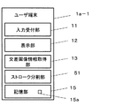
図1は、第1の実施形態に係る描画処理装置の構成図である。
同図に示すユーザ端末1a−1の構成は、ユーザによる入力を受け付ける入力受付部11と、画像を表示する表示部12と、交差画像情報を取得する交差画像情報取得部13と、交差画像情報(描画入力ストローク情報)を複数に分割して所定の削除動作を行うストローク分割部51と、記憶部15と、を備える。
記憶部15は、一時的にデータを記憶する一次記憶部15aを有する。
<User terminal>
(First embodiment)
〔Constitution〕
FIG. 1 is a configuration diagram of a drawing processing apparatus according to the first embodiment.
The configuration of the
The
入力受付部11が受け付ける情報(入力情報)は、描画入力情報と、削除入力情報とがある。入力情報は、様々なオブジェクト(テキスト、図形、画像、etc.)であるが、ここではポインティング・デバイスを用いて単純なストローク(少なくとも一つ以上の座標の要素から構成され、順序を持ったリスト)が入力された場合(手書き入力とも称す)を例として説明する。
Information (input information) received by the
描画/削除の切り替えは、例えば図2に示すようなラジオボタン(複数の選択項目の中から一つだけを選択するための仕組み)で行われても良く、それぞれ専用の入力装置(描画入力を行うペン型デバイス、削除入力を行うイレイサー型デバイス)を用いても良い。 Switching between drawing / deletion may be performed by, for example, a radio button (a mechanism for selecting only one of a plurality of selection items) as shown in FIG. A pen-type device to be performed or an eraser-type device to perform deletion input) may be used.
描画入力受付モードの場合に受け付けた入力情報(ここでは、ポインティング・デバイスを用いて単純なストロークが入力された場合)は「描画入力ストローク」と称し、削除入力受付モードの場合に受け付けた入力情報(同様に単純なストロークが入力された場合)は「削除入力ストローク」と称す。 The input information received in the drawing input acceptance mode (here, when a simple stroke is input using a pointing device) is referred to as a “drawing input stroke”, and the input information received in the deletion input acceptance mode. (When a simple stroke is input in the same manner) is referred to as “deletion input stroke”.
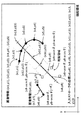
図3に、描画入力ストローク及び削除入力ストロークを図示する。
θは削除入力ストロークの連続する二点を結ぶ直線とx軸とのなす角度である。丸にバツ印は削除入力ストロークの両端を示し、四角印は削除領域の端部を示している。削除領域は削除入力ストロークのストローク間隔(例えば10pix)ごとに生成される。尚、削除領域の形状は図では正方形であるが、限定されるものではなく、長方形、円形、楕円形、多角形のいずれであってもよい。
FIG. 3 illustrates a drawing input stroke and a deletion input stroke.
θ is an angle formed by a straight line connecting two consecutive points of the deletion input stroke and the x axis. The circles indicate the ends of the deletion input stroke, and the squares indicate the ends of the deletion area. The deletion area is generated every stroke interval (for example, 10 pix) of the deletion input stroke. The shape of the deletion area is a square in the figure, but is not limited, and may be any of a rectangle, a circle, an ellipse, and a polygon.
さらに、描画/削除入力ストロークは、座標の組に基づく情報(座標データ)、例えば(x1,y1), (x2,y2),..., (xn,yn)として認識される。 Further, the drawing / deleting input stroke is recognized as information (coordinate data) based on a set of coordinates, for example, (x1, y1), (x2, y2),..., (Xn, yn).
ユーザ端末1a−1が備える交差画像情報取得部13が取得する交差画像情報とは、削除入力ストロークと交差する描画入力ストローク(例えば図3の描画入力ストローク1、2)の座標データである。交差画像情報は、座標データ((x1,y1),(x2,y2),...,(xn,yn))の他、識別子、色、線の太さ、透明度、線の種類(破線、一点鎖線など)、生成時刻、更新時刻、当該オブジェクトの外接矩形の左上端点の位置座標などが含まれてもよい。
The intersection image information acquired by the intersection image
ここで、「識別子」とは、それぞれの描画入力ストロークに対する一意の識別子である。例えば図3においては描画入力ストローク1の識別子をID:1(表記形式は任意)、描画入力ストローク2の識別子をID:2としても良い。
Here, the “identifier” is a unique identifier for each drawing input stroke. For example, in FIG. 3, the identifier of the drawing
「更新時刻」とは、描画入力ストロークの「移動」操作による移動時刻がセットされた時刻である。 The “update time” is the time when the movement time by the “movement” operation of the drawing input stroke is set.
「生成時刻」、「更新時刻」、「当該オブジェクトの外接矩形の左上端点の位置座標」は、上記識別子の代替として、描画入力ストロークを識別するために利用される。 “Generation time”, “update time”, and “position coordinates of the upper left corner of the circumscribed rectangle of the object” are used to identify the drawing input stroke as an alternative to the identifier.
記憶部15は、一次記憶部(RAM;Random Access Memory、揮発性メモリ)15aを用いても良く、不揮発性メモリ(ROM;Read Only Memory)であっても良い。
The
〔動作処理〕
第1の実施形態に係るユーザ端末1a−1の動作処理を図4のフローチャートに示す。
ユーザは図2に示すような描画画面に対して描画入力や、削除入力を行う。描画入力/削除入力は、図2に示すラジオボタン等を用いて入力受付モードを切り替えることで行う場合を例として説明する。
[Operation processing]
The operation process of the
The user performs drawing input or deletion input on the drawing screen as shown in FIG. A case where the drawing input / deletion input is performed by switching the input reception mode using the radio button or the like shown in FIG. 2 will be described as an example.
ユーザ端末1a−1は、描画入力受付モードで受付けた場合(ステップS1/Yes)、ユーザからの入力ストロークは描画入力ストロークとして取得し(ステップS2)、一次記憶部15aに保存し(ステップS3)、一次記憶部15aに保存されているストロークを全て描画する(ステップS4)。
When the
ユーザ端末1a−1は、描画入力受付モードではない場合、つまり削除入力受付モードの場合(ステップS1/No)、ユーザからの入力ストロークは削除入力ストロークとして取得し(ステップS5)、交差画像情報を取得する(ステップS6)。
When the
ここで、交差画像情報について図5を用いて説明する。
例えば、ユーザ端末1a−1は、削除入力ストロークの座標のいずれかが、描画入力ストロークを含む4点で囲まれた外接矩形領域内に含まれるか否かによって判別しても良い。
Here, the intersection image information will be described with reference to FIG.
For example, the
図5では、描画入力ストロークAの外接矩形領域内に、削除入力ストロークの座標(x10,y10)及び(x11,y11)が含まれるため、描画入力ストロークAが、削除入力ストロークと交差する交差画像となる。描画入力ストロークBは、その外接矩形領域内に削除入力ストロークの座標がいずれも含まれないため、交差画像とはならない。 In FIG. 5, since the coordinates (x10, y10) and (x11, y11) of the deletion input stroke are included in the circumscribed rectangular area of the drawing input stroke A, the intersecting image in which the drawing input stroke A intersects the deletion input stroke. It becomes. The drawing input stroke B is not an intersecting image because none of the coordinates of the deletion input stroke is included in the circumscribed rectangular area.
削除入力ストロークと交差する描画入力ストロークの情報を、交差画像情報と称す。 Information on the drawing input stroke that intersects the deletion input stroke is referred to as intersecting image information.
ユーザ端末1a−1は、当該削除入力ストローク情報に従い、削除領域(図3参照)を取得する(ステップS7)。削除領域は削除入力ストロークのストローク間隔(例えば10pix)ごとに生成されても良い。例えば、削除入力ストローク情報が((x5,y5),(x6,y6))である場合、削除領域はそれぞれ下記(1),(2),(3),(4)の4点で囲まれる長方形としても良い(図3参照)。
The

ユーザ端末1a−1は、上記削除領域に含まれる、交差画像情報の座標を記憶部15から削除し(ステップS8)、表示部12の表示から削除する。
The
次に、さらに具体的に、描画処理装置で削除入力ストロークが入力された場合の、ストローク分割部51によるストローク情報の分割について図6及び図7を用いて詳述する。
図6は、本実施形態に係るストローク分割部51による分割前の状態を説明するための図である。図7は、本実施形態に係るストローク分割部による分割後の状態を説明するための図である。
Next, more specifically, division of stroke information by the
FIG. 6 is a diagram for explaining a state before the division by the
まず、ユーザからの入力が以下のようなものであった場合を想定する。
ここでは、入力受付部11としてマウスを用いる。
ユーザのマウス操作により削除入力ストローク((x8,y8), (x9,y9), (x10,y10), (x11,y11), (x12,y12))が入力された場合、交差画像情報取得部13は、かかる削除入力ストロークと交差する描画入力ストロークの座標(図6では描画入力ストローク1、(x1,y1), (x2,y2), (x3,y3), (x4,y4), (x5,y5))を取得し、記憶部15に保存する。
First, it is assumed that the input from the user is as follows.
Here, a mouse is used as the
When the delete input stroke ((x8, y8), (x9, y9), (x10, y10), (x11, y11), (x12, y12)) is input by the user's mouse operation, the intersection image information acquisition
次に、ユーザ端末1a−1は、記憶部15から、削除入力ストローク情報と、前記交差する描画入力ストロークの座標(図6描画入力ストローク1)とを「交差画像情報」として取得し、各座標が各削除領域内(図6参照)に含まれるか否かを算出し(算出方法は下記)、含まれる座標を削除して新たなストローク(少なくとも一つ以上の座標の要素から構成され、順序を持ったリスト)を生成する(図7、画像情報3,4)。
Next, the
ユーザ端末1a−1は、ストローク分割部51で生成された新たなストローク(図7、画像情報3,4)と、交差画像情報と重複しない描画入力ストローク(図7、画像情報2)を描画ストロークとして生成し、記憶部15の一次記憶部15aに保存し、一次記憶部15aに保存された全てを描画する(ステップS9)。
The
<ストローク分割部の算出方法>
ここで、ストローク分割部51が、交差画像情報の各座標が削除入力ストロークの各削除領域内に含まれるか否かを算出する方法について図6を例として参照しながら説明する。
<Calculation method of stroke division part>
Here, a method in which the
以上の算出方法を、削除入力ストローク座標の各連続する2点毎に行っていく。 The above calculation method is performed for every two consecutive points of the deletion input stroke coordinates.
このように、本実施形態では、ユーザが入力した情報(例えば手書きオブジェクト(ポインティング・デバイスを用いて入力した画像データ))を、ユーザ端末にて座標データとして取り扱うことで、画質の劣化を抑制しつつ、かつ入力情報中の任意の箇所を削除することができ(画像データ内の任意の箇所の削除も可能)、ユーザの描画処理装置の利用の利便性を向上することができる。これは、通常はビットマップデータを用いるところ本願ではベクトルデータを用いるためである。 As described above, in the present embodiment, information input by the user (for example, a handwritten object (image data input using a pointing device)) is handled as coordinate data at the user terminal, thereby suppressing deterioration in image quality. At the same time, any part of the input information can be deleted (any part in the image data can be deleted), and the convenience of the user to use the drawing processing apparatus can be improved. This is because, in the present application, vector data is used where bitmap data is normally used.
<サーバ装置>
(第2の実施形態)
〔構成〕
図8は、第2の実施形態に係る描画処理システムの全体構成図である。
同図に示すシステムは、1つのPC(以下、ユーザ端末と称す)1a−2と、サーバ装置2−1とが、ネットワーク3で接続された描画処理システムである。
第2の実施形態は、第1の実施形態と比較すると、ユーザ端末1a−2が、第1の実施形態と同様の入力受付部11、表示部12、及び交差画像情報取得部13を備え、サーバ装置2−1は第1の実施形態におけるストローク分割部51に相当するストローク分割部22を備える。
本実施形態ではさらにそれぞれ、ユーザ端末1a−2は、描画処理要求生成部52と記憶部15とを備え、サーバ装置2−1は、描画処理要求受付部26、応答生成部23、および記憶部24をさらに備える。ここで第1の実施形態と同一の構成要素についてはその説明を省略する。
<Server device>
(Second Embodiment)
〔Constitution〕
FIG. 8 is an overall configuration diagram of a drawing processing system according to the second embodiment.
The system shown in the figure is a drawing processing system in which one PC (hereinafter referred to as a user terminal) 1 a-2 and a server device 2-1 are connected via a
In the second embodiment, compared to the first embodiment, the
In the present embodiment, each of the
ユーザ端末1a−2は、ユーザによる入力を受け付ける入力受付部11と、画像を表示する表示部12と、交差画像情報を取得する交差画像情報取得部13と、入力されたストローク情報及び取得した交差画像情報を含んだ描画処理要求を生成する描画処理要求生成部52とを備える。
The
ユーザ端末1a−2が備える描画処理要求生成部52が生成する描画処理要求は、今回受け付けた入力ストローク情報(入力ストロークの座標データ)と、取得した交差画像情報とを含む。すなわち、ユーザ端末1a−2は、一入力ごと、一ストロークごと、マウスダウンから直後のマウスアップまでごとに、描画処理要求を生成する。さらに、サーバ装置2−1の識別情報(ホスト名、もしくはIPアドレスを指し、下記URLの例におけるsomewhere)を含む。
The drawing process request generated by the drawing process
描画処理要求はURI(Uniform Resource Identifier)などで表され、URL(Uniform Resource Locator)で表されてもよい。例えばURLであればsomewhereというサーバ装置のcanvasという描画対象において、
・描画入力された場合(描画入力ストローク1 (x1,y1),(x2,y2))は、下記(13)の形式
http://somewhere/canvas?cmd=draw&pos=x1,y1,x2,y2 ・・・(13)
・削除入力された場合(削除入力ストローク (x5,y5),(x6,y6))は、下記(14)の形式(なお、該削除入力ストロークは2つのオブジェクト((x1,y1),(x2,y2)と(x3,y3),(x4,y4))と交差している)
The drawing process request may be represented by a URI (Uniform Resource Identifier) or the like, and may be represented by a URL (Uniform Resource Locator). For example, if the URL is a drawing object called canvas on a server device called somewhere,
-When drawing is input (drawing input stroke 1 (x1, y1), (x2, y2)), the following format (13)
http: // somewhere / canvas? cmd = draw & pos = x1, y1, x2, y2 (13)
-When a deletion is entered (deletion input stroke (x5, y5), (x6, y6)), the following format (14) (note that the deletion input stroke consists of two objects ((x1, y1), (x2 , y2) and (x3, y3), (x4, y4)))
http://somewhere/canvas?cmd=erase&pos1=x1,y1,x2,y2&pos2=x3,y3,x4,y4&pos3=x5,y5,x6,y6 ・・・(14)
で指定しても良い。
http: // somewhere / canvas? cmd = erase & pos1 = x1, y1, x2, y2 & pos2 = x3, y3, x4, y4 & pos3 = x5, y5, x6, y6 (14)
You may specify with.
サーバ装置2−1は、ユーザ端末1a−2から送信された描画処理要求を受け付ける描画処理要求受付部26と、描画処理要求に削除入力ストローク情報が含まれている場合に交差画像情報(描画入力ストローク情報)を複数に分割して所定の削除動作を行うストローク分割部22と、描画処理要求への応答情報を生成する応答生成部23と、ストローク情報、およびストローク情報の識別子を記憶する記憶部24と、を備える。
The server device 2-1 receives the drawing process
サーバ装置2−1の応答生成部23が生成する応答情報には、分割後の複数の描画入力ストローク情報が含まれる場合もある。
The response information generated by the
描画処理要求の応答情報に含まれるデータの記述形式はJSON(Java(登録商標)Script Object Notation)、またはXML(eXtensible Markup Language)のように構造化された形式で記述されてもよく、テキスト形式のように構造化されていない形式でもよい。例えばJSON形式であれば、下記(15)のような形式で指定してもよい。
["cmd":"draw", "result":[["id":pos1,"pos":[[x1,y1],[x2,y2]]],["id":pos2,"pos":[[x3,y3],[x4,y4]]]]]
・・・(15)
The description format of the data included in the response information of the rendering processing request may be described in a structured format such as JSON (Java (Script) Script Object Notation) or XML (eXtensible Markup Language). An unstructured form such as For example, in the JSON format, it may be specified in the following format (15).
["cmd": "draw", "result": [["id": pos1, "pos": [[x1, y1], [x2, y2]]], ["id": pos2, "pos" : [[x3, y3], [x4, y4]]]]]
... (15)
ユーザ端末1a−2とサーバ装置2−1とは、HTTP(Hyper Text Transfer Protocol)で通信してもよい。応答情報は、HTTPレスポンスとして取得されてもよい。
The
〔動作処理〕
第2の実施形態に係る描画処理システムの動作処理を図9のフローチャートに示す。ここで前記第1の実施形態と同一の構成要素については説明を省略する。
ユーザは図2に示すような描画画面に対して描画入力や、削除入力を行う。描画入力/削除入力は、図2に示すラジオボタン等を用いて入力受付モードを切り替えることで行う場合を例として説明する。
ユーザ端末1a−2は、描画入力受付モードで受付けた場合(ステップS1/Yes)、ユーザからの入力ストロークは描画入力ストロークとして取得し(ステップS2)、当該描画入力ストロークを含む描画処理要求(1)を生成する(ステップS5)。
[Operation processing]
An operation process of the drawing processing system according to the second embodiment is shown in a flowchart of FIG. Here, the description of the same components as those in the first embodiment is omitted.
The user performs drawing input or deletion input on the drawing screen as shown in FIG. A case where the drawing input / deletion input is performed by switching the input reception mode using the radio button or the like shown in FIG. 2 will be described as an example.
When the
ユーザ端末1a−2は、描画入力受付モードではない場合、つまり削除入力受付モードの場合(ステップS1/No)、ユーザからの入力ストロークは削除入力ストロークとして取得し(ステップS3)、当該削除入力ストロークと交差する描画入力ストロークの情報(座標データ)を交差画像情報として取得する(ステップS4)。
When the
ユーザ端末1a−2の描画処理要求生成部52は、削除入力ストローク情報と交差画像情報とを含む描画処理要求(2)を生成する(ステップS5)。ユーザ端末1a−2は、生成した描画処理要求をサーバ装置2−1に送信する(ステップS6)。
The drawing process
以上説明したように、配信要求生成部は、描画入力ストローク情報を含むもの(描画処理要求(1))、若しくは削除入力ストローク情報及び交差画像情報を含むもの(描画処理要求(2))を生成し、描画処理装置に送信する。 As described above, the distribution request generation unit generates a drawing input stroke information (drawing processing request (1)) or a deletion input stroke information and crossing image information (drawing processing request (2)). To the drawing processing apparatus.
一方、サーバ装置2−1は、描画処理要求を受信し(ステップS9)、描画処理要求に削除入力ストローク情報が含まれていなければ((1)を受信すれば) (ステップS10/No)、描画処理要求に含まれる描画入力ストローク情報をそのまま一次記憶部(記憶部24)に保存し(ステップS14)、一次記憶部の内容を参照して応答情報(3)を生成し(ステップS15)、ユーザ端末1a−2へ送信する(ステップS16)。なお、ここでは「一次記憶部」に保存しているが、記憶部は揮発性メモリ、不揮発性メモリのいずれでも良い。
On the other hand, the server device 2-1 receives the drawing process request (step S9), and if the drawing process request does not include the deletion input stroke information (if (1) is received) (step S10 / No), The drawing input stroke information included in the drawing processing request is directly stored in the primary storage unit (storage unit 24) (step S14), and the response information (3) is generated by referring to the contents of the primary storage unit (step S15). It transmits to the
サーバ装置2−1は、描画処理要求に削除入力ストローク情報が含まれていれば((2)を受信すれば) (ステップS10/Yes)、当該削除入力ストローク情報に従い削除領域を取得する(ステップS11)。ここで削除領域は第1の実施形態と同様の処理により取得される。 If the delete input stroke information is included in the drawing process request (if (2) is received) (step S10 / Yes), the server device 2-1 acquires a delete area according to the delete input stroke information (step S10). S11). Here, the deletion area is acquired by the same processing as in the first embodiment.
その後、サーバ装置2−1は、描画入力ストロークの全ての座標について、上記削除領域に含まれるか否かを判別し(ステップS12)、削除領域に含まれない座標を一次記憶部に保存する(ステップS13)。 Thereafter, the server device 2-1 determines whether or not all the coordinates of the drawing input stroke are included in the deletion area (step S12), and stores the coordinates not included in the deletion area in the primary storage unit (step S12). Step S13).
サーバ装置2−1は、描画入力ストロークの全ての座標について判別が終了したら(ステップS12/No)、一次記憶部の内容を参照して応答情報を生成し(ステップS15)、ユーザ端末1a−2へ送信する(ステップS16)。
When the determination is completed for all the coordinates of the drawing input stroke (step S12 / No), the server device 2-1 generates response information with reference to the contents of the primary storage unit (step S15), and the
上述したように、応答生成部23が生成する応答情報には、分割後の複数のストローク情報を含んでも良い。
As described above, the response information generated by the
ここで、ユーザ端末1a−2で削除入力ストロークが入力された場合の、サーバ装置2−1側のストローク分割部によるストローク情報の分割については、第1の実施形態と同様の処理となる。
Here, when the deletion input stroke is input at the
まず、ユーザ端末1a−2から送信される描画処理要求が以下のようなものであった場合を想定する。ここでは、入力受付部11としてマウスを用いる。ユーザのマウス操作により削除入力ストローク((x8,y8), (x9,y9), (x10,y10), (x11,y11), (x12,y12))が入力された場合、交差画像情報取得部13は、かかる削除入力ストロークと交差する描画入力ストロークの座標(図6では描画入力ストローク1、(x1,y1), (x2,y2), (x3,y3), (x4,y4), (x5,y5))を取得し、記憶部15に保存する。
First, it is assumed that the drawing processing request transmitted from the
次に、描画処理要求生成部52は、記憶部15から、削除入力ストローク情報と、交差する描画入力ストロークの座標(図6描画入力ストローク1)とを取得し、これらを含む描画処理要求(2)を生成し、サーバ装置2−1に送信する。
Next, the drawing process
そして、ユーザ端末1a−2から送信された上記描画処理要求(2)を受信したサーバ装置2−1では、ストローク分割部22において、配信要求(2)に含まれる「交差画像情報」の各座標が、各削除領域内(図6参照)に含まれるか否かを算出し(算出方法は下記)、含まれる座標を削除して新たなストローク(少なくとも一つ以上の座標の要素から構成され、順序を持ったリスト)を生成する(図7、画像情報3,4)。
Then, in the server device 2-1 that has received the drawing processing request (2) transmitted from the
そして応答生成部23は、ストローク分割部22で生成された新たなストローク(図7、画像情報3,4)と、交差画像情報と重複しない描画入力ストローク(図7、画像情報2)を含む応答情報を生成し、ユーザ端末1a−2に返送する。
Then, the
このように、本実施形態では、ユーザが入力した情報(例えば手書きオブジェクト(ポインティング・デバイスを用いて入力した画像データ))を、座標データとして取り扱うことで、ネットワーク負荷を軽減でき、かつ入力情報中の任意の箇所を削除することができ(画像データ内の任意の箇所の削除も可能)、ユーザの描画処理システム利用の利便性を向上することができる。 As described above, in this embodiment, information input by the user (for example, a handwritten object (image data input using a pointing device)) is handled as coordinate data, so that the network load can be reduced and the input information can be reduced. Can be deleted (it is possible to delete any part in the image data), and the convenience of the user to use the drawing processing system can be improved.
<描画処理システム>
(第3の実施形態)
〔構成〕
図10は、第3の実施形態に係る描画処理システムの全体構成図である。
同図に示すシステムは、少なくとも1以上のPC(以下、ユーザ端末と称す)(本実施形態ではユーザ端末1a−3、1b〜1nを図示)と、サーバ装置2−2とが、ネットワーク3で接続された描画処理システムである。
第3の実施形態は、第2の実施形態と比較すると、ユーザ端末1a−3、1b〜1nが、配信要求生成部14、配信要求生成部14を備える。ここで第2の実施形態と同一の構成要素についてはその説明を省略する。
<Drawing processing system>
(Third embodiment)
〔Constitution〕
FIG. 10 is an overall configuration diagram of a drawing processing system according to the third embodiment.
In the system shown in the figure, at least one or more PCs (hereinafter referred to as user terminals) (in this embodiment,
In the third embodiment, the
ユーザ端末1a−3の構成は1b〜1nにおいて同様であるが、ここでは1a−3を用いて説明する。ユーザ端末1a−3は、ユーザによる入力を受け付ける入力受付部11と、画像を表示する表示部12と、交差画像情報を取得する交差画像情報取得部13と、入力されたストローク情報及び取得した交差画像情報を含んだ配信要求を生成する配信要求生成部14を備える。
The configuration of the
ユーザ端末1a−3が備える配信要求生成部14が生成する配信要求は、今回受け付けた入力ストローク情報(入力ストロークの座標データ)と、取得した交差画像情報とを含む。すなわち、一入力ごと、一ストロークごと、マウスダウンから直後のマウスアップまでごとに、配信要求を生成する。さらに、サーバ装置2−2の識別情報(ホスト名、もしくはIPアドレスを指し、下記URLの例におけるsomewhere)を含む。
The distribution request generated by the distribution
配信要求はURI(Uniform Resource Identifier)などで表され、URL(Uniform Resource Locator)で表されてもよい。例えばURLであればsomewhereというサーバ装置のcanvasという描画対象において、
・描画入力された場合(描画入力ストローク1 (x1,y1),(x2,y2))は、下記(16)の形式
http://somewhere/canvas?cmd=draw&pos=x1,y1,x2,y2 ・・・(16)
・削除入力された場合(削除入力ストローク (x5,y5),(x6,y6))は、下記(17)の形式
(なお、該削除入力ストロークは2つのオブジェクト((x1,y1),(x2,y2)と(x3,y3),(x4,y4))と交差している)
http://somewhere/canvas?cmd=erase&pos1=x1,y1,x2,y2&pos2=x3,y3,x4,y4&pos3=x5,y5,x6,y6 ・・・(17)
で指定しても良い。
The distribution request is represented by a URI (Uniform Resource Identifier) or the like, and may be represented by a URL (Uniform Resource Locator). For example, if the URL is a drawing object called canvas on a server device called somewhere,
-When drawing is input (drawing input stroke 1 (x1, y1), (x2, y2)), the following format (16)
http: // somewhere / canvas? cmd = draw & pos = x1, y1, x2, y2 (16)
・ When a deletion is entered (deletion input stroke (x5, y5), (x6, y6)), the following format (17) (Note that the deletion input stroke consists of two objects ((x1, y1), (x2 , y2) and (x3, y3), (x4, y4)))
http: // somewhere / canvas? cmd = erase & pos1 = x1, y1, x2, y2 & pos2 = x3, y3, x4, y4 & pos3 = x5, y5, x6, y6 (17)
You may specify with.
サーバ装置2−2は、ユーザ端末1a−3から送信された配信要求を受け付ける配信要求受付部21と、配信要求に削除入力ストローク情報が含まれている場合に交差画像情報(描画入力ストローク情報)を複数に分割して所定の削除動作を行うストローク分割部22と、配信要求への応答情報を生成する応答生成部23と、記憶部24と、を備える。
The server device 2-2 includes a distribution
応答生成部23が生成する応答情報には、分割後の複数の描画入力ストローク情報が含まれる場合もある。
The response information generated by the
配信要求の応答情報に含まれるデータの記述形式はJSON(Java(登録商標)Script Object Notation)、またはXML(eXtensible Markup Language)のように構造化された形式で記述されてもよく、テキスト形式のように構造化されていない形式でもよい。例えばJSON形式であれば、下記(18)のような形式で指定してもよい。
["cmd":"draw", "result":[["id":pos1,"pos":[[x1,y1],[x2,y2]]],["id":pos2,"pos":[[x3,y3],[x4,y4]]]]] ・・・(18)
The description format of the data included in the response information of the delivery request may be described in a structured format such as JSON (Java (registered trademark) Script Object Notation) or XML (eXtensible Markup Language). An unstructured form may be used. For example, in the JSON format, it may be specified in the following format (18).
["cmd": "draw", "result": [["id": pos1, "pos": [[x1, y1], [x2, y2]]], ["id": pos2, "pos" : [[x3, y3], [x4, y4]]]]] ... (18)
ユーザ端末1a−3とサーバ装置2−2は、HTTP(Hyper Text Transfer Protocol)で通信してもよい。応答情報は、ユーザ端末1a−3からサーバ装置3に生成された二つのHTTPコネクション(HTTP POSTメソッドで入力を行う入力用コネクションとHTTP GETメソッドでポーリングを行う応答取得用コネクション)の応答取得用コネクションのHTTPレスポンスとして取得されてもよい。
The
記憶部15は、一次記憶(RAM;Random Access Memory、揮発性メモリ)として用いても良く、不揮発性メモリ(ROM;Read Only Memory)でも良い。
The
〔動作処理〕
第3の実施形態に係る描画処理システムの動作処理を図11のフローチャートに示す。
ここで第2の実施形態と同一の構成要素については説明を省略する。
ユーザは図2に示すような描画画面に対して描画入力や、削除入力を行う。描画入力/削除入力は、図2に示すラジオボタン等を用いて入力受付モードを切り替えることで行う場合を例として説明する。
[Operation processing]
An operation process of the drawing processing system according to the third embodiment is shown in a flowchart of FIG.
Here, the description of the same components as those of the second embodiment is omitted.
The user performs drawing input or deletion input on the drawing screen as shown in FIG. A case where the drawing input / deletion input is performed by switching the input reception mode using the radio button or the like shown in FIG. 2 will be described as an example.
ユーザ端末1a−3は、描画入力受付モードで受付けた場合(ステップS1/Yes)、ユーザからの入力ストロークは描画入力ストロークとして取得し(ステップS2)、当該描画入力ストロークを含む配信要求(1)を生成する(ステップS5)。
When the
ユーザ端末1a−3は、描画入力受付モードではない場合、つまり削除入力受付モードの場合(ステップS1/No)、ユーザからの入力ストロークは削除入力ストロークとして取得し(ステップS3)、当該削除入力ストロークと交差する描画入力ストロークの情報(座標データ)を交差画像情報として取得する(ステップS4)。
When the
配信要求生成部14は、削除入力ストローク情報と交差画像情報とを含む配信要求(2)を生成する(ステップS5)。ユーザ端末1a−3は、生成した配信要求をサーバ装置2−2に送信する(ステップS6)。
The distribution
以上説明したように、配信要求生成部14は、描画入力ストローク情報を含むもの(配信要求(1))、若しくは削除入力ストローク情報及び交差画像情報を含むもの(配信要求(2))を生成し、サーバ装置2−2に送信する。
As described above, the distribution
一方、サーバ装置2−2は、配信要求を受信し(ステップS9)、配信要求に削除入力ストローク情報が含まれていなければ((1)を受信すれば) (ステップS10/No)、配信要求に含まれる描画入力ストローク情報をそのまま記憶部24もしくは一次記憶部24aに保存し(ステップS14)、一次記憶部24aの内容を参照して応答情報(3)を生成し(ステップS15)、ユーザ端末1a−3へ送信する(ステップS16)。なお、ここでは「一次記憶部」に保存しているが、記憶部24は揮発性メモリ、不揮発性メモリのいずれでも良い。
On the other hand, the server device 2-2 receives the distribution request (step S9). If the deletion request stroke information is not included in the distribution request (if (1) is received) (step S10 / No), the distribution request Is stored in the
サーバ装置2−2は、配信要求に削除入力ストローク情報が含まれていれば((2)を受信すれば) (ステップS10/Yes)、削除入力ストローク情報に従い削除領域(図3参照)を取得する(ステップS11)。ここで削除領域は第1の実施形態と同様の処理により取得される。 If deletion input stroke information is included in the distribution request (if (2) is received) (step S10 / Yes), the server device 2-2 acquires a deletion area (see FIG. 3) according to the deletion input stroke information. (Step S11). Here, the deletion area is acquired by the same processing as in the first embodiment.
その後、サーバ装置2−2は、描画入力ストロークの全ての座標について、上記削除領域に含まれるか否かを判別し(ステップS12)、削除領域に含まれない座標を一次記憶部に保存する(ステップS13)。 Thereafter, the server device 2-2 determines whether or not all the coordinates of the drawing input stroke are included in the deletion area (step S12), and stores the coordinates not included in the deletion area in the primary storage unit (step S12). Step S13).
サーバ装置2−2は、描画入力ストロークの全ての座標について判別が終了したら(ステップS12/No)、一次記憶の内容を参照して応答情報を生成し(ステップS15)、ユーザ端末1aへ送信する(ステップS16)。
上述したように、応答生成部23が生成する応答情報には、分割後の複数のストローク情報を含んでも良い。
When the determination is completed for all coordinates of the drawing input stroke (step S12 / No), the server device 2-2 generates response information with reference to the contents of the primary storage (step S15) and transmits the response information to the
As described above, the response information generated by the
ここで、ユーザ端末1aで削除入力ストロークが入力された場合の、サーバ装置2−2側のストローク分割部によるストローク情報の分割については第2の実施形態と同様の処理となる。
Here, when the deletion input stroke is input at the
ここで、他ユーザ端末1b〜1nにて入力された描画入力ストローク情報の共有について図12のフローチャートを用いて説明する。図11に示すフローチャートの動作処理と同一の処理については同一ステップ番号を振り、その説明を省略する。
Here, sharing of drawing input stroke information input in the
共有化は、まず入力受け付け前(スタート直後)に、各ユーザ端末1a−3、1b〜1nがサーバ装置2−2に対して、情報共有要求を送信する(ステップS30)。
サーバ装置2−2は、受付けた情報共有要求の応答を保留する(ステップS31)。その後、応答情報送信後(ステップS16)に、保留している情報要求の応答を行う(ステップS32、S33)。描画入力が行われないユーザ端末1a−3は情報共有要求の送信(S30)とその応答の受信(S34)のみを行うことにより、他ユーザ端末1b〜1nにて描画入力された描画入力ストローク情報を共有することが可能となる。
For sharing, first, each
The server apparatus 2-2 holds the response to the accepted information sharing request (step S31). Thereafter, after the response information is transmitted (step S16), a response to the pending information request is made (steps S32 and S33). The
このように、本実施形態では、ユーザが入力した情報(例えば手書きオブジェクト(ポインティング・デバイスを用いて入力した画像データ))を、座標データとして取り扱うことで、情報共有の際のネットワーク負荷を軽減でき、かつ入力情報中の任意の箇所を削除することができ(画像データ内の任意の箇所の削除も可能)、ユーザの描画処理システム利用の利便性を向上することができる。 As described above, in this embodiment, information input by the user (for example, a handwritten object (image data input using a pointing device)) is handled as coordinate data, thereby reducing the network load during information sharing. In addition, any part of the input information can be deleted (any part in the image data can be deleted), and the convenience of the user to use the drawing processing system can be improved.
<ユーザ端末の操作>
(速度に応じた削除)
(第4の実施形態)
〔構成〕
図13は、第4の実施形態に係るユーザ端末の全体構成図である。
第4の実施形態は、第1の実施形態と比較すると、本実施形態に係るユーザ端末が、削除入力ストロークの移動速度を算出する移動速度算出部54と、移動速度に応じて削除領域を生成する削除領域生成部55とをさらに備え、ストローク分割部53が、生成された削除領域に含まれる描画入力ストロークの座標を削除(ストロークを分割して削除)することを特徴とする。第1の実施形態と同一の構成要素についてはその説明を省略する。
<User terminal operation>
(Delete according to speed)
(Fourth embodiment)
〔Constitution〕
FIG. 13 is an overall configuration diagram of a user terminal according to the fourth embodiment.
In the fourth embodiment, compared to the first embodiment, the user terminal according to this embodiment generates a deletion area according to the movement speed, and a movement
すなわち本実施形態では、移動速度に応じて削除領域の大きさを決定するため、一度の削除入力ストロークの入力操作で、多くの画像オブジェクトを削除することも可能である。ユーザは、削除作業を行う際に、例えば従来のようなイレイサー(eraser)の幅を段階的に変更できるメニューの操作を行わずに済む。多くの画像オブジェクトを削除する場合は、削除入力ストロークを速い速度で入力すれば良い。 That is, in the present embodiment, since the size of the deletion area is determined according to the moving speed, it is possible to delete many image objects by a single deletion input stroke input operation. When performing the deletion operation, the user does not have to operate a menu that can change the width of an eraser in a stepwise manner, for example. When deleting many image objects, the deletion input stroke may be input at a high speed.
〔動作処理〕
第4の実施形態に係る描画処理装置の動作処理を示すフローチャートを図14に示す。
図14に示す第1実施形態の動作処理と同一の処理については同一ステップ番号を振り、その説明を省略する。
[Operation processing]
FIG. 14 is a flowchart showing the operation process of the drawing processing apparatus according to the fourth embodiment.
The same step number is assigned to the same process as the operation process of the first embodiment shown in FIG. 14, and the description thereof is omitted.
第4の実施形態では、描画入力受付モードでない場合、すなわち削除入力受付モードの場合に(ステップS1/No)、ユーザ端末1a−4は、受付けた入力ストロークを削除入力ストロークとして取得する(ステップS3)。
In the fourth embodiment, when not in the drawing input acceptance mode, that is, in the deletion input acceptance mode (step S1 / No), the
ユーザ端末1a−4は、削除入力ストロークを受付けた場合、交差画像情報取得部13は当該削除入力ストロークと交差する描画入力ストロークの座標データ(交差画像情報)を取得する(ステップS6)。さらに、移動速度算出部54は、当該削除入力ストロークの入力開始時(例えばマウスダウン時)と入力終了時(例えばマウスアップ時)の経過時間[sec]と距離[pixel]から、移動速度を算出する(ステップS7)。
When the
次に削除領域生成部は、削除入力ストローク情報及び移動速度から、削除領域を取得する(ステップS8)。 Next, the deletion area generation unit acquires a deletion area from the deletion input stroke information and the moving speed (step S8).
図15は、本実施形態に係る削除領域の大きさの相違を例示する図である。
削除領域が、例えば4点で囲まれる長方形とした場合に、削除領域生成部55は、移動速度に応じて長方形の大きさを決定する(例えば図15に示す削除領域1、削除領域2)。
FIG. 15 is a diagram illustrating a difference in the size of the deletion area according to the present embodiment.
When the deletion area is, for example, a rectangle surrounded by four points, the deletion
ユーザの操作の利便性を考慮し、領域閾値a=0.75v[pixel]、v:取得した移動速度として例えば1000[pixel/s]としてもよい。本係数0.75は移動速度に対する削除領域の広がりやすさを示し、削除領域の広がりやすさに比例する係数であるが限定されるものではない。 In consideration of the convenience of the user's operation, the area threshold value a = 0.75 v [pixel], and v: the acquired movement speed may be set to 1000 [pixel / s], for example. This coefficient 0.75 indicates the ease of expansion of the deletion area with respect to the moving speed, and is a coefficient proportional to the ease of expansion of the deletion area, but is not limited thereto.
その後、削除領域に含まれない座標を一次記憶部15aに保存する(ステップS9)。以降の動作処理は図4に示す動作処理と同様であるため、その説明を省略する。
Thereafter, the coordinates not included in the deletion area are stored in the
以上説明したように、本実施形態では、削除入力ストロークの移動速度に応じて削除領域を生成することで、削除領域の切り替え操作をシームレスに実現できる。
ここで、シームレスとは、ユーザが削除領域の削除幅を予め決めておいたとしても、自動的に設定が変更され、例えば、削除入力ストロークの速度を速くしたり、移動距離を長くしたりした場合には削除幅が増加し、これとは逆に削除入力ストロークの速度を遅くしたり、移動距離を短くしたりした場合には削除幅が減少することができることを意味する。尚、削除処理後は元の設定に復帰するようになっている。
これにより、ユーザは、削除作業の度に、例えば削除領域の大きさを選択するメニュー操作を行わずに済み、効率的に操作することができる。
As described above, in the present embodiment, the deletion area switching operation can be seamlessly realized by generating the deletion area according to the movement speed of the deletion input stroke.
Here, seamless means that even if the user has determined the deletion width of the deletion area in advance, the setting is automatically changed. For example, the speed of the deletion input stroke is increased or the movement distance is increased. In this case, the deletion width increases. On the contrary, if the speed of the deletion input stroke is decreased or the movement distance is shortened, it means that the deletion width can be reduced. Note that after the deletion process, the original setting is restored.
Thus, the user does not have to perform a menu operation for selecting the size of the deletion area, for example, every time the deletion operation is performed, and can operate efficiently.
(長さに応じた削除)
(第5の実施形態)
〔構成〕
図16は、第5の実施形態に係る描画処理装置の全体構成図である。
第5の実施形態は、第4の実施形態と比較すると、本実施形態に係るユーザ端末1a−5が、削除入力ストロークの移動長を算出する移動長算出部56と、移動長に応じて削除領域を生成する削除領域生成部57とをさらに備えることを特徴とする。第4の実施形態と同一の構成要素についてはその説明を省略する。
(Delete according to length)
(Fifth embodiment)
〔Constitution〕
FIG. 16 is an overall configuration diagram of a drawing processing apparatus according to the fifth embodiment.
In the fifth embodiment, compared to the fourth embodiment, the
すなわち本実施形態では、削除入力の移動長に応じて削除領域の大きさを決定するため、一度の削除入力ストロークの入力操作で、多くの画像オブジェクトを削除することも可能である。ユーザは、削除作業を行う際に、例えば従来のようなイレイサー(eraser)の幅を段階的に変更できるメニューの操作を行わずに済む。多くの画像オブジェクトを削除する場合は、削除入力ストロークの移動距離を長くすれば良い。 That is, in the present embodiment, since the size of the deletion area is determined according to the movement length of the deletion input, it is possible to delete many image objects with a single deletion input stroke input operation. When performing the deletion operation, the user does not have to operate a menu that can change the width of an eraser in a stepwise manner, for example. When deleting many image objects, the moving distance of the deletion input stroke may be increased.
〔動作処理〕
第5の実施形態に係る描画処理装置の動作処理を示すフローチャートを図17に示す。図15に示す第4実施形態の動作処理と同一の処理については同一ステップ番号を振り、その説明を省略する。
[Operation processing]
FIG. 17 is a flowchart showing the operation process of the drawing processing apparatus according to the fifth embodiment. The same step numbers are assigned to the same processes as those of the fourth embodiment shown in FIG. 15, and the description thereof is omitted.
第5の実施形態では、ユーザ端末1a−5が削除入力ストロークを受付けた場合、交差画像情報取得部13は当該削除入力ストロークと交差する描画入力ストロークの座標データ(交差画像情報)を取得する(ステップS6)。さらに、移動長算出部56は、当該削除入力ストロークの入力開始時(例えばマウスダウン時)から入力終了時(例えばマウスアップ時)までの距離[pixel]から、移動長を算出する(ステップS7)。
In the fifth embodiment, when the
次に削除領域生成部57は、削除入力ストローク情報及び移動長から、削除領域を取得する(ステップS8)。
Next, the deletion
ユーザの操作の利便性を考慮し、領域閾値a=0.75L[pixel]、L:取得した移動長として例えば1000[pixel]としてもよい。本係数は移動長に対する削除領域の広がりやすさを示すが限定されるものではない。 Considering the convenience of the user's operation, the area threshold value a = 0.75 L [pixel], and L: the acquired movement length may be set to 1000 [pixel], for example. This coefficient indicates the ease of expanding the deletion area with respect to the movement length, but is not limited.
その後、ユーザ端末1a−5は、削除領域に含まれない座標を一次記憶部に保存する(ステップS9)。以降の動作処理は図4に示す動作処理と同様であるため、その説明を省略する。
Thereafter, the
以上説明したように、本実施形態では、削除入力ストロークの移動長に応じて削除領域を生成することで、削除領域の切り替え操作をモードレスに実現できる。これにより、ユーザは、削除作業の度に、例えば削除領域の大きさを選択するメニュー操作を行わずに済み、効率的に操作することができる。 As described above, in this embodiment, the deletion area can be switched modelessly by generating the deletion area according to the movement length of the deletion input stroke. Thus, the user does not have to perform a menu operation for selecting the size of the deletion area, for example, every time the deletion operation is performed, and can operate efficiently.
(形状に応じた削除)
(第6の実施形態)
〔構成〕
図18は、第6の実施形態に係る描画処理システムの全体構成を示す図である。
第6の実施形態は、第4、第5の実施形態と比較すると、ユーザ端末1a−6が、削除入力ストロークが閉曲線を形成するか否かを算出する閉曲線算出部59をさらに備え、ストローク分割部51は、削除入力ストロークが閉曲線であるときにはその内側に、描画入力ストロークを構成する座標のいずれかが含まれている場合は、当該描画入力ストロークを構成する全ての座標(つまり描画入力ストローク全体、オブジェクト自体)を削除し、閉曲線でないときには上述した各実施形態と同様に削除領域を取得してその内側に含まれる描画入力ストロークの座標を削除(部分削除)することを特徴とする。第4、第5の実施形態と同一の構成要素についてはその説明を省略する。
(Delete according to shape)
(Sixth embodiment)
〔Constitution〕
FIG. 18 is a diagram illustrating an overall configuration of a drawing processing system according to the sixth embodiment.
Compared with the fourth and fifth embodiments, the sixth embodiment further includes a closed
第6の実施形態に係る描画処理装置の動作処理を示すフローチャートを図19に示す。
図17に示す第4の実施形態の動作処理と同一の処理については同一ステップ番号を振り、その説明を省略する。
FIG. 19 is a flowchart showing an operation process of the drawing processing apparatus according to the sixth embodiment.
The same step numbers are assigned to the same processes as those of the fourth embodiment shown in FIG. 17, and the description thereof is omitted.
第6の実施形態では、ユーザ端末1a−6は、削除入力ストロークを受け付けた場合(ステップS1/No)、閉曲線算出部59により削除入力ストロークが閉曲線であるか否かを判別する(ステップS6)。
In the sixth embodiment, when receiving the deletion input stroke (step S1 / No), the
ユーザ端末1a−6は、閉曲線であれば、削除入力ストロークである閉曲線の内側に、描画入力ストロークを構成する座標のいずれかが含まれている場合は当該描画入力ストロークを構成する全ての座標を削除する(ステップS7)。
If the
ユーザ端末1a−6は、閉曲線算出部59による閉曲線の判別について図20を用いて説明する。
閉曲線算出部59による閉曲線の判別は、例えば図20に示すように、削除入力ストロークの入力開始時(例えばマウスダウン時)の座標が(x7,y7)であり、入力終了時(例えばマウスアップ時)の座標が(x14,y14)であり、その中間の座標が(x8,y8),(x9,y9),(x10,y10),(x11,y11),(x12,y12),(x13,y13)であり、下記(19)の条件式かつ(20)の条件式が、真であるときは閉曲線であり、真でないときは閉曲線でないと判別してもよい。
The
For example, as shown in FIG. 20, the closed
なお、上記実施形態では、削除入力ストロークである閉曲線の内側に、描画入力ストロークを構成する座標のいずれかが含まれている場合は当該描画入力ストロークを構成する全ての座標を削除しているが、閉曲線の削除領域に含まれる場合にも、描画入力ストロークの削除を行っても良い(図21参照)。これにより、閉曲線外にあるストロークも削除することが可能となり、利便性が向上する。 In the above embodiment, when any of the coordinates constituting the drawing input stroke is included inside the closed curve as the deletion input stroke, all the coordinates constituting the drawing input stroke are deleted. The drawing input stroke may be deleted even when it is included in the deletion area of the closed curve (see FIG. 21). This makes it possible to delete strokes that are outside the closed curve, improving convenience.
以上説明したように、本実施形態では、ストローク情報が閉曲線か否かを判別することで、オブジェクトの部分削除と、オブジェクト自体の削除との切り替え操作をモードレスに実現できる。これにより、ユーザが作業の度に、オブジェクトの部分削除か、オブジェクト自体の削除かのメニュー操作を行わずに済み、効率的に操作することができる。 As described above, in this embodiment, it is possible to realize a modeless switching operation between partial deletion of an object and deletion of the object itself by determining whether or not the stroke information is a closed curve. Thereby, it is not necessary to perform a menu operation for deleting a part of the object or deleting the object itself every time the user performs a work, and the user can operate efficiently.
(削除予定部分のグレーアウト)
(第7の実施形態)
〔構成〕
第7の実施形態は、第1の実施形態と比較して、削除交差画像情報の座標のうち削除される部分を、描画入力、および削除入力と異なる色で表示することを特徴とする。第1の実施形態と同一の構成要素についてはその説明を省略する。
(Grayed out part to be deleted)
(Seventh embodiment)
〔Constitution〕
Compared with the first embodiment, the seventh embodiment is characterized in that the deleted portion of the coordinates of the deleted intersection image information is displayed in a color different from the drawing input and the deletion input. The description of the same components as those in the first embodiment is omitted.
図22のように、本実施形態において、例えば、描画入力を実線(実画面では黒色線)、削除入力を太破線(実画面では赤色線)、削除される部分を細破線(実画面ではグレー色線)により表示しても良い。すなわち、削除する予定の図形の表示(色もしくは線種)が変化し、最終的にどこが削除されるかをユーザが確認することができ、マウスアップ後は削除予定部分が削除されるようになっている。
ここで、削除予定部分は削除入力の線と描画入力された線とが交差した部分である。
As shown in FIG. 22, in this embodiment, for example, the drawing input is a solid line (black line on the real screen), the deletion input is a thick broken line (red line on the real screen), and the part to be deleted is a thin broken line (gray on the real screen). (Color line) may be displayed. In other words, the display (color or line type) of the figure to be deleted changes so that the user can confirm where it will eventually be deleted, and the scheduled deletion part will be deleted after mouse-up. ing.
Here, the portion to be deleted is a portion where a line for deletion input and a line for drawing input intersect.
〔動作処理〕
第7の実施形態に係るユーザ端末の動作処理を示すフローチャートを図23に示す。図4に示す第1実施形態の動作処理と同一の処理については同一ステップ番号を振り、その説明を省略する。
[Operation processing]
FIG. 23 shows a flowchart showing the operation process of the user terminal according to the seventh embodiment. The same step number is assigned to the same process as the operation process of the first embodiment shown in FIG. 4, and the description thereof is omitted.
ユーザ端末は、削除入力受付モードの場合(ステップS1/No)、ユーザからの入力ストロークは削除入力ストロークとして取得し(ステップS5)、交差画像情報を取得する(ステップS6)。
ユーザ端末は、削除入力ストローク情報に従い、削除領域を取得し(ステップS7)、その削除領域に含まれるストローク(座標、および線分)をグレー表示する(ステップS8)。
ユーザ端末は、その後、削除確定操作(例えばマウスアップ)の有無を判別し(ステップS9)、有れば、削除領域に含まれる座標を一次記憶部15aから削除し(ステップS9)、ストロークを描画する(ステップS4)。無ければ、何も実行せず終了する。
In the deletion input acceptance mode (step S1 / No), the user terminal acquires an input stroke from the user as a deletion input stroke (step S5), and acquires crossing image information (step S6).
The user terminal acquires a deletion area in accordance with the deletion input stroke information (step S7), and displays a stroke (coordinates and line segment) included in the deletion area in gray (step S8).
Thereafter, the user terminal determines whether or not there is a deletion confirmation operation (for example, mouse up) (step S9), and if there is, deletes the coordinates included in the deletion area from the
以上説明したように、本実施形態では、削除されるストロークを描画入力、削除入力と異なる色で表示することで、ユーザが削除ストロークを事前に確認でき、操作ミスを回避することができる。 As described above, in the present embodiment, by displaying the deleted stroke in a color different from the drawing input and the deletion input, the user can confirm the deleted stroke in advance and avoid an operation error.
(復元操作)
(第8の実施形態)
〔構成〕
図25は、第8の実施形態に関わる描画処理装置の構成図である。
第1の実施形態と比較して、削除入力により削除された座標を復元するストローク復元部60を備えたことを特徴とする。
第1の実施形態と同一の構成要素についてはその説明を省略する。
一次記憶部15aは、削除前のデータを一時的に保持する、LIFO(LAST IN FIRST OUT:最後に書き込んだデータが最初に読み出される)形式のメモリである。
ここでストローク復元部60は図27の「元に戻す」ボタンによって、実行されても良い。
(Restore operation)
(Eighth embodiment)
〔Constitution〕
FIG. 25 is a configuration diagram of a drawing processing apparatus according to the eighth embodiment.
Compared to the first embodiment, a
The description of the same components as those in the first embodiment is omitted.
The
Here, the
〔動作処理〕
第8の実施形態に係るユーザ端末の動作処理を図26のフローチャートに示す。ここで第1の実施形態と同一の構成要素については説明を省略する。
[Operation processing]
The operation process of the user terminal according to the eighth embodiment is shown in the flowchart of FIG. Here, the description of the same components as those in the first embodiment is omitted.
第8の実施形態では、ユーザ端末1aは、ユーザによる操作がストローク復元操作か否かを判別し(ステップS10)、復元操作であれば記憶部15もしくは一次記憶部(スタック)15aから直前の交差画像情報を取得し(ステップS11)、描画する(ステップS4)。復元操作でなければ、削除入力受付モードの場合(ステップS1/No)、ユーザからの入力ストロークは削除入力ストロークとして取得し(ステップS5)、交差画像情報を取得する(ステップS6)。交差画像情報を一次記憶部(スタック)15aに保存する(ステップS7)。
ユーザ端末1a−7は、入力ストローク情報に従い、削除領域を取得し(ステップS7)、削除領域に含まれる座標を一次記憶部15aから削除し(ステップS9)、ストロークを描画する(ステップS4)。
In the eighth embodiment, the
The
以上説明したように、本実施形態では、削除したストロークを復元することができ、操作ミスで削除してしまった場合でも容易に復元することができる。 As described above, in this embodiment, the deleted stroke can be restored, and even if it is deleted due to an operation mistake, it can be easily restored.
<サーバの操作>
(速度に応じた削除)
<Server operation>
(Delete according to speed)
(第9の実施形態)
〔構成〕
図28は、第9の実施形態に係る描画処理システムの全体構成図である。
第9の実施形態は、第2の実施形態と比較すると、本実施形態に係るシステムのサーバ装置2−3が、削除入力ストロークの移動速度に応じて削除領域を生成する削除領域生成部57を備え、ストローク分割部22が、生成された削除領域に含まれる描画入力ストロークの座標を削除(ストロークを分割して削除)することを特徴とする。第2の実施形態と同一の構成要素についてはその説明を省略する。
(Ninth embodiment)
〔Constitution〕
FIG. 28 is an overall configuration diagram of a drawing processing system according to the ninth embodiment.
In the ninth embodiment, when compared with the second embodiment, the server apparatus 2-3 of the system according to the present embodiment includes a deletion
すなわち本実施形態では、移動速度に応じて削除領域の大きさを決定するため、一度の削除入力ストロークの入力操作で、多くの画像オブジェクトを削除することも可能である。ユーザは、削除作業を行う際に、例えば従来のようなイレイサー(eraser)の幅を段階的に変更できるメニューの操作を行わずに済む。多くの画像オブジェクトを削除する場合は、削除入力ストロークを速い速度で入力すれば良い。 That is, in the present embodiment, since the size of the deletion area is determined according to the moving speed, it is possible to delete many image objects by a single deletion input stroke input operation. When performing the deletion operation, the user does not have to operate a menu that can change the width of an eraser in a stepwise manner, for example. When deleting many image objects, the deletion input stroke may be input at a high speed.
〔動作処理〕
第9の実施形態に係る描画処理システムの動作処理を示すフローチャートを図29に示す。図9に示す第1実施形態の動作処理と同一の処理については同一ステップ番号を振り、その説明を省略する。
[Operation processing]
FIG. 29 is a flowchart showing the operation processing of the drawing processing system according to the ninth embodiment. The same step numbers are assigned to the same processes as those of the first embodiment shown in FIG. 9, and the description thereof is omitted.
第9の実施形態では、描画処理システムは、描画入力受付モードでない場合、すなわち削除入力受付モードの場合に(ステップS1/No)、受付けた入力ストロークを削除入力ストロークとして取得する(ステップS3)。 In the ninth embodiment, when the drawing processing system is not in the drawing input acceptance mode, that is, in the deletion input acceptance mode (step S1 / No), the drawing processing system acquires the accepted input stroke as the deletion input stroke (step S3).
描画処理システムは、削除入力ストロークを受付けた場合、交差画像情報取得部13は当該削除入力ストロークと交差する描画入力ストロークの座標データ(交差画像情報)を取得する(ステップS4)。さらに、移動速度算出部16は、当該削除入力ストロークの入力開始時(例えばマウスダウン時)と入力終了時(例えばマウスアップ時)の経過時間[sec]と距離[pixel]から、移動速度を算出する(ステップS17)。
When the drawing processing system accepts the deletion input stroke, the intersection image
交差画像情報取得部13が取得した交差画像情報と、移動速度算出部16が算出した移動速度は、記憶部15に保存される。
The intersection image information acquired by the intersection image
このとき描画処理要求生成部52は、全ての削除/描画入力ストロークと、交差画像情報と、移動速度とを、記憶部15から抽出し、描画処理要求を生成する(ステップS18)。
At this time, the drawing process
次に、ユーザ端末1a−8から描画処理要求を受信したサーバ装置2−3の動作処理について説明する。受信した描画処理要求に削除入力ストロークが含まれていれば(描画処理要求を受信すれば)(ステップS10/Yes)、削除領域生成部57は、描画処理要求に含まれる削除入力ストローク情報及び移動速度から、削除領域を取得する(ステップS9)。
ここで削除領域生成に関する処理は第4の実施形態と同様であるので説明を省略する。
Next, an operation process of the server apparatus 2-3 that has received a drawing process request from the
Here, the process related to the deletion area generation is the same as that in the fourth embodiment, and thus the description thereof is omitted.
その後、サーバ装置2−3は、描画入力ストロークの全ての座標について、上記削除領域に含まれるか否かを判別し(ステップS12)、削除領域に含まれない座標を一次記憶部としての記憶部24に保存する(ステップS13)。以降の動作処理は図9に示す動作処理と同様であるため、その説明を省略する。 Thereafter, the server device 2-3 determines whether or not all the coordinates of the drawing input stroke are included in the deletion area (step S12), and stores the coordinates not included in the deletion area as a primary storage unit. 24 (step S13). The subsequent operation processing is the same as the operation processing shown in FIG.
以上説明したように、本実施形態では、削除入力ストロークの移動速度に応じて削除領域を生成することで、削除領域の切り替え操作をモードレスに実現できる。これにより、ユーザは、削除作業の度に、例えば削除領域の大きさを選択するメニュー操作を行わずに済み、効率的に操作することができる。 As described above, in the present embodiment, the deletion area switching operation can be realized in a modeless manner by generating the deletion area according to the moving speed of the deletion input stroke. Thus, the user does not have to perform a menu operation for selecting the size of the deletion area, for example, every time the deletion operation is performed, and can operate efficiently.
(長さに応じた削除)
(第10の実施形態)
〔構成〕
図30は、第10の実施形態に係る描画処理システムの全体構成図である。
第10の実施形態は、第9の実施形態に比較すると、本実施形態に係るシステムのサーバ装置2−4が、削除入力ストロークの移動長に応じて削除領域を生成する削除領域生成部57をさらに備えることを特徴とする。第9の実施形態と同一の構成要素についてはその説明を省略する。
(Delete according to length)
(Tenth embodiment)
〔Constitution〕
FIG. 30 is an overall configuration diagram of a drawing processing system according to the tenth embodiment.
The tenth embodiment is different from the ninth embodiment in that the server apparatus 2-4 of the system according to the present embodiment includes a deletion
すなわち本実施形態では、削除入力の移動長に応じて削除領域の大きさを決定するため、一度の削除入力ストロークの入力操作で、多くの画像オブジェクトを削除することも可能である。ユーザは、削除作業を行う際に、例えばイレイサー(eraser)の幅を段階的に変更できるメニューの操作を行わずに済む。多くの画像オブジェクトを削除する場合は、削除入力ストロークの移動距離を長くすれば良い。 That is, in the present embodiment, since the size of the deletion area is determined according to the movement length of the deletion input, it is possible to delete many image objects with a single deletion input stroke input operation. The user does not have to operate a menu that can change the width of the eraser step by step, for example, when performing the deletion operation. When deleting many image objects, the moving distance of the deletion input stroke may be increased.
〔動作処理〕
第10の実施形態に係る描画処理システムの動作処理を示すフローチャートを図31に示す。図29に示す第1実施形態の動作処理と同一の処理については同一ステップ番号を振り、その説明を省略する。
[Operation processing]
FIG. 31 is a flowchart showing the operation process of the drawing processing system according to the tenth embodiment. The same step numbers are assigned to the same processes as those of the first embodiment shown in FIG. 29, and the description thereof is omitted.
第10の実施形態では、ユーザ端末1a−9が、削除入力ストロークを受付けた場合、交差画像情報取得部13は当該削除入力ストロークと交差する描画入力ストロークの座標データ(交差画像情報)を取得する(ステップS4)。さらに、移動長算出部56は、当該削除入力ストロークの入力開始時(例えばマウスダウン時)と入力終了時(例えばマウスアップ時)の距離[pixel]から、移動長を算出する(ステップS17)。
In the tenth embodiment, when the
交差画像情報取得部13が取得した交差画像情報と、移動速度算出部16が算出した移動速度とは、記憶部15に保存される。
The intersection image information acquired by the intersection image
このとき描画処理要求生成部52は、全ての削除/描画入力ストロークと、交差画像情報と、移動速度とを、記憶部15から抽出し、描画処理要求を生成する(ステップS18)。
At this time, the drawing process
次に、ユーザ端末1a−9から描画処理要求を受信したサーバ装置2−4の動作処理について説明する。
サーバ装置2−4は、受信した描画処理要求に削除入力ストロークが含まれていれば(描画処理要求を受信すれば)(ステップS10/Yes)、削除領域生成部57は、描画処理要求に含まれる削除入力ストローク情報及び移動長から、削除領域を取得する(ステップS9)。
ここで削除領域生成に関する処理は第4の実施形態と同様であるので説明を省略する。
Next, an operation process of the server apparatus 2-4 that has received the drawing process request from the
If the deletion input stroke is included in the received drawing process request (if the drawing process request is received) (step S10 / Yes), the server apparatus 2-4 includes the deletion
Here, the process related to the deletion area generation is the same as that in the fourth embodiment, and thus the description thereof is omitted.
その後、サーバ装置2−4は、描画入力ストロークの全ての座標について、上記削除領域に含まれるか否かを判別し(ステップS12)、削除領域に含まれない座標を記憶部24の一次記憶部24aに保存する(ステップS13)。以降の動作処理は図29に示す動作処理と同様であるため、その説明を省略する。
Thereafter, the server device 2-4 determines whether or not all the coordinates of the drawing input stroke are included in the deletion area (step S12), and the coordinates not included in the deletion area are stored in the primary storage unit of the
以上説明したように、本実施形態では、削除入力ストロークの移動長に応じて削除領域を生成することで、削除領域の切り替え操作をモードレスに実現できる。これにより、ユーザは、削除作業の度に、例えば削除領域の大きさを選択するメニュー操作を行わずに済み、効率的に操作することができる。 As described above, in this embodiment, the deletion area can be switched modelessly by generating the deletion area according to the movement length of the deletion input stroke. Thus, the user does not have to perform a menu operation for selecting the size of the deletion area, for example, every time the deletion operation is performed, and can operate efficiently.
(形状に応じた削除)
(第11の実施形態)
〔構成〕
図32は、第11の実施形態に係る描画処理システムの全体構成を示す図である。
第11の実施形態は、第9、10の実施形態と比較すると、ユーザ端末1a−10が、削除入力ストロークが閉曲線を形成するか否かを判別する閉曲線算出部59を備え、サーバ装置2−5が、ストローク分割機能を含むストローク分割部22とを備え、ストローク分割部22は、削除入力ストロークが閉曲線であるときにはその内側に、描画入力ストロークを構成する座標のいずれかが含まれている場合は、当該描画入力ストロークを構成する全ての座標(つまり描画入力ストローク全体、オブジェクト自体)を削除し、閉曲線でないときには上述した各実施形態と同様に削除領域を取得してその内側に含まれる描画入力ストロークの座標を削除(部分削除)することを特徴とする。第1の実施形態と同一の構成要素についてはその説明を省略する。
(Delete according to shape)
(Eleventh embodiment)
〔Constitution〕
FIG. 32 is a diagram showing an overall configuration of a drawing processing system according to the eleventh embodiment.
Compared with the ninth and tenth embodiments, the eleventh embodiment includes a closed
第11の実施形態に係る描画処理システムの動作処理を示すフローチャートを図33に示す。
図29、31に示す第9、10実施形態の動作処理と同一の処理については同一ステップ番号を振り、その説明を省略する。
FIG. 33 is a flowchart showing the operation processing of the drawing processing system according to the eleventh embodiment.
The same step numbers are assigned to the same processes as those of the ninth and tenth embodiments shown in FIGS. 29 and 31, and the description thereof is omitted.
第11の実施形態では、削除入力ストロークを受付けた場合、閉曲線算出部により削除入力ストロークが閉曲線であるか否かを算出する(ステップS17)。 In the eleventh embodiment, when a deletion input stroke is accepted, the closed curve calculation unit calculates whether or not the deletion input stroke is a closed curve (step S17).
閉曲線の可否を一次記憶部15aに保存し、閉曲線でなければ交差画像情報取得部13が取得した交差画像情報を一次記憶部15aに保存する。このとき描画処理要求生成部52は、全ての削除/描画入力ストロークと、交差画像情報と、閉曲線の可否とを、記憶部15から抽出し、描画処理要求を生成する(ステップS5)。
ここで閉曲線算出部59の処理については第6の実施形態と同様であるため、説明を省略する。
Whether the closed curve is acceptable is stored in the
Here, since the processing of the closed
次に、ユーザ端末1a−10から描画処理要求を受信したサーバ装置2−5の動作処理について説明する。
受信した描画処理要求に削除入力ストロークが含まれていれば(描画処理要求を受信すれば)(ステップS9/Yes)、削除入力ストロークが閉曲線を形成するか否かを判別する(ステップS17)。
閉曲線を形成している場合、削除入力ストロークの内側に、描画入力ストロークを構成する座標のいずれかが含まれている場合は当該描画入力ストロークを構成する全ての座標を削除するため、当該描画入力ストロークの識別子(削除すべき描画入力ストロークの識別子)から応答情報を生成し(ステップS15)、ユーザ端末1a−10へ送信する(ステップS16)。
Next, an operation process of the server apparatus 2-5 that has received a drawing process request from the
If a delete input stroke is included in the received drawing process request (if a drawing process request is received) (step S9 / Yes), it is determined whether or not the delete input stroke forms a closed curve (step S17).
When a closed curve is formed, if any of the coordinates constituting the drawing input stroke is included inside the deletion input stroke, all the coordinates constituting the drawing input stroke are deleted. Response information is generated from the stroke identifier (identifier of the drawing input stroke to be deleted) (step S15) and transmitted to the
削除処理により、pos1,pos2で識別されるストロークが削除された場合は、応答情報は下記(21)のようなJSON形式で指定されても良い。
["cmd":"erase","id":[pos1,pos2]] ・・・(21)
When the strokes identified by pos1 and pos2 are deleted by the deletion process, the response information may be specified in the JSON format as shown in (21) below.
["cmd": "erase", "id": [pos1, pos2]] (21)
以上説明したように、本実施形態では、ストローク情報が閉曲線か否かを判別することで、オブジェクトの部分削除と、オブジェクト自体の削除との切り替え操作をモードレスに実現できる。これにより、ユーザが作業の度に、オブジェクトの部分削除か、オブジェクト自体の削除かのメニュー操作を行わずに済み、効率的に操作することができる。 As described above, in this embodiment, it is possible to realize a modeless switching operation between partial deletion of an object and deletion of the object itself by determining whether or not the stroke information is a closed curve. Thereby, it is not necessary to perform a menu operation for deleting a part of the object or deleting the object itself every time the user performs a work, and the user can operate efficiently.
(復元操作)
(第12の実施形態)
〔構成〕
図34は、第12の実施形態に関わる描画処理装置の構成図である。
第8の実施形態と比較して、削除入力により削除された座標を復元するストローク復元部60を備えたことを特徴とする。
第8の実施形態と同一の構成要素についてはその説明を省略する。
ユーザ端末1a−10は、図27の「元に戻す」ボタンが押下されると、下記(22)の形式で描画処理要求を発行する。
http://somewhere/canvas?cmd=undo ・・・(22)
(Restore operation)
(Twelfth embodiment)
〔Constitution〕
FIG. 34 is a configuration diagram of a drawing processing apparatus according to the twelfth embodiment.
Compared to the eighth embodiment, a
The description of the same components as those in the eighth embodiment is omitted.
When the “undo” button in FIG. 27 is pressed, the
http: // somewhere / canvas? cmd = undo (22)
サーバ装置2−6は、描画処理要求を受け付けると、一次記憶部15a(スタック)から直前の交差画像情報を取得し、交差画像情報を含む応答情報を生成する。この応答情報は例えば、JSON形式であれば、下記(23)のような形式で指定しても良い(ここでは交差画像情報pos1((x1,y1),(x2,y2))、pos2((x3,y3),(x4,y4))が直前に削除されたとする)。
["cmd":"undo", "result":[["id":pos1,"pos":[[x1,y1],[x2,y2]]],["id":pos2,"pos":[[x3,y3],[x4,y4]]]]] ・・・(23)
When the server apparatus 2-6 receives the drawing process request, the server apparatus 2-6 acquires the immediately preceding intersection image information from the
["cmd": "undo", "result": [["id": pos1, "pos": [[x1, y1], [x2, y2]]], ["id": pos2, "pos" : [[x3, y3], [x4, y4]]]]] ... (23)
もし、サーバ装置2−6が描画処理要求を受け付けなければ、ユーザ端末1a−10は、削除入力が含まれるかを判別し、含まれれば描画処理要求に含まれる交差画像情報を一次記憶(スタック)部15aに保存する。
以降の処理は第11の実施形態と同様であるため説明を省略する。
If the server apparatus 2-6 does not accept the drawing process request, the
Subsequent processing is the same as that of the eleventh embodiment, and thus description thereof is omitted.
以上説明したように、本実施形態では、削除したストロークを復元することができ、操作ミスで削除してしまった場合でも容易に復元することができる。 As described above, in this embodiment, the deleted stroke can be restored, and even if it is deleted due to an operation mistake, it can be easily restored.
<ハードウェア構成>
以上の各実施形態に係るユーザ端末1、サーバ装置2の基本的なハードウェア構成を説明する。
<Hardware configuration>
A basic hardware configuration of the
ユーザ端末1は、会議の各参加者が情報の参照や入力、編集等を行うためにそれぞれ使用する情報処理装置100であって、デスクトップ型パーソナルコンピュータやノート型パーソナルコンピュータ、PDA(Personal Digital Assistants)と称される携帯用情報端末等が適用される。なお、ここではノート型パーソナルコンピュータを例に、ユーザ端末1のハードウェア構成(情報処理装置に内蔵される各部の電気的接続を示すブロック構成)について図36を参照して説明する。図36は、本発明の実施形態に係る情報処理装置100(ユーザ端末1)のハードウェア構成図である。
The
図36に示すように、情報処理装置100(ユーザ端末1)は、システム全体を制御するCPU(Central Processing Unit)101と、起動プログラム等を記憶したROM(Read Only Memory)102と、CPU101のワークエリアとして使用されるRAM(Random Access Memory)103とを備えたコンピュータ構成とされ、文字・数値・各種指示等の入力を行うためのキーボード104と、ポインティング・デバイス105と、ハードディスク106と、LCD(Liquid Crystal Display)であるディスプレイ等の表示部107と、ネットワーク3に接続するためのネットワークI/F108と、上記各部を接続するためのバス109とを備える。
As shown in FIG. 36, the information processing apparatus 100 (user terminal 1) includes a CPU (Central Processing Unit) 101 that controls the entire system, a ROM (Read Only Memory) 102 that stores an activation program, and the work of the
ポインティング・デバイス105は、一般的にカーソルの移動や範囲選択等を行うためのマウスやタッチパッド、トラックボール等であることはもちろんであるが、本発明では特に、座標検出を行う情報入力部である。
The
例えば、マウスのようなポインティング・デバイスを座標検出装置として認識し、入力動作イベントとして、「マウスボタンダウン」が入力開始、「マウスボタンアップ」が入力終了、「マウスボタンダウン&ムーブ」が入力したまま移動(ストローク)の各イベントに対応するものとする。 For example, a pointing device such as a mouse is recognized as a coordinate detection device. As an input operation event, “mouse button down” starts input, “mouse button up” ends input, and “mouse button down & move” inputs. It shall correspond to each event of movement (stroke).
座標検出を行う情報入力部は、マウスの他、例えば、指先やペン等の指示手段で指示された座標検出領域内の座標位置を検出する情報入力部でも良い。また、当該情報入力部が、表示部として機能するディスプレイの表示面側に位置するようにして一体化されたタッチパネル形式の情報入出力部(1つの面が情報を表示(出力)する面及び入力(書き込み)する面として機能)でも良い。 The information input unit that performs coordinate detection may be an information input unit that detects a coordinate position in a coordinate detection region specified by an instruction unit such as a fingertip or a pen, in addition to a mouse. Further, an information input / output unit in a touch panel form integrated so that the information input unit is positioned on the display surface side of the display functioning as a display unit (a surface on which one surface displays (outputs information) and an input) (Function as a (writing) surface).
座標検出には、光遮蔽式(特開2000−105671号公報)、指示手段を挿入することで座標検出領域内の光束を反射してその指示位置を検出する光反射方式、座標検出領域内の指示手段をカメラで撮像してその指示位置を検出するカメラ撮像方式、LEDアレイ方式、超音波弾性波方式、アナログ容量結合方式、感圧方式等を適用することも可能である。 For coordinate detection, a light shielding method (Japanese Patent Laid-Open No. 2000-105671), a light reflection method for detecting the indicated position by reflecting a light beam in the coordinate detection area by inserting an instruction means, and in the coordinate detection area It is also possible to apply a camera imaging method, an LED array method, an ultrasonic acoustic wave method, an analog capacitive coupling method, a pressure-sensitive method, etc., in which the instruction means is imaged with a camera and the indicated position is detected.
ハードディスク106には、オペレーティング・システム(OS)110、描画ソフト・ワードプロセッサソフト・表計算ソフト・プレゼンテーションソフト等の各種アプリケーションプログラム(AP)111等が記憶されている。
The
サーバ装置2は、各ユーザ端末からの入力情報を共有化する情報処理装置200である。サーバ装置2のハードウェア構成(情報処理装置に内蔵される各部の電気的接続を示すブロック構成)について図37を参照して説明する。図37は、本発明の実施形態に係る情報処理装置200(サーバ装置2)のハードウェア構成図である。
The
図37に示すように、情報処理装置200(サーバ装置2)は、システム全体を制御するCPU201と、起動プログラム等を記憶したROM202と、CPU201のワークエリアとして使用されるRAM203とを備えたコンピュータ構成とされ、文字・数値・各種指示等の入力を行うためのキーボード204と、マウス205と、ハードディスク206と、表示部207と、ネットワーク3に接続するためのネットワークI/F208と、上記各部を接続するためのバス209とを備える。
As shown in FIG. 37, the information processing apparatus 200 (server apparatus 2) has a computer configuration including a
ハードディスク206には、オペレーティング・システム(OS)210、描画ソフト・ワードプロセッサソフト・表計算ソフト・プレゼンテーションソフト等の各種アプリケーションプログラム(AP)211等が記憶されている。
The
<プログラム>
なお、各図のフローチャートに示す処理を、各CPUが実行するためのプログラムは本発明によるプログラムを構成する。このプログラムを記録する記録媒体としては、半導体記憶部や光学的及び/又は磁気的な記憶部等を用いることができる。このようなプログラム及び記録媒体を、前述した各実施形態とは異なる構成のシステム等で用い、そこのCPUで上記プログラムを実行させることにより、本発明と実質的に同じ効果を得ることができる。
<Program>
Note that the program for each CPU to execute the processing shown in the flowcharts of the respective drawings constitutes a program according to the present invention. As a recording medium for recording the program, a semiconductor storage unit, an optical and / or magnetic storage unit, or the like can be used. By using such a program and a recording medium in a system having a configuration different from that of each of the above-described embodiments and causing the CPU to execute the program, substantially the same effect as the present invention can be obtained.
以上、本発明を好適な実施形態に基づき具体的に説明したが、本発明は上記のものに限定されるものではなく、その要旨を逸脱しない範囲で種々変更可能であることは言うまでもない。 Although the present invention has been specifically described above based on the preferred embodiments, it is needless to say that the present invention is not limited to the above-described ones and can be variously modified without departing from the gist thereof.
1a−1〜1a−11、1b〜1n ユーザ端末
2−1〜2−6 サーバ装置
3 ネットワーク
11 入力受付部
12 表示部
13 交差画像情報取得部
14 配信要求生成部
15 記憶部
15a 一次記憶部
16 移動速度算出部
21 配信要求受付部
22 ストローク分割部
23 応答生成部
24 記憶部
25、57 削除領域生成部
26 描画処理要求受付部
27 ストローク削除部
51 ストローク分割部
56 移動長算出部
59 閉曲線算出部
60 ストローク復元部
100 情報処理装置(ユーザ端末1)
200 情報処理装置(サーバ装置)
101、201 CPU
102、202 ROM
103、203 RAM
104、204 キーボード
105 ポインティング・デバイス
205 マウス
106、206 ハードディスク
107、207 表示部
108、208 ネットワークI/F
109、209 バス
110、210 オペレーティング・システム(OS)
111、211 各種アプリケーションプログラム(AP)
1a-1 to 1a-11, 1b to 1n User terminals 2-1 to 2-6
200 Information processing device (server device)
101, 201 CPU
102, 202 ROM
103, 203 RAM
104, 204
109, 209
111, 211 Various application programs (AP)
Claims (12)
前記入力受付手段によって受け付けられた削除入力に関する情報と交差する描画入力に関する情報を交差画像に関する情報として取得する交差画像情報取得手段と、
前記入力受付手段によって受け付けられた削除入力のモーションを算出するモーション算出手段と、
前記モーション算出手段によって算出された削除入力が閉曲線を形成するか否かを算出する閉曲線算出手段と、
前記閉曲線算出手段によって前記削除入力ストロークが閉曲線を形成すると算出された場合、その内側に、前記描画入力ストロークを構成する座標のいずれかが含まれている場合は、当該描画入力ストロークを構成する全ての座標を削除する第1の削除手段と、
前記閉曲線算出手段によって前記削除入力が閉曲線を形成しないと算出された場合、前記交差画像を分割し、該分割された交差画像の内側に含まれる前記削除入力のストロークの座標を削除する第2の削除手段と、
を備えることを特徴とするユーザ端末装置。 Input receiving means for receiving information related to drawing input or information related to deletion input;
Crossing image information acquisition means for acquiring information on drawing input that intersects information on deletion input received by the input receiving means as information on crossing images;
A motion calculating means for calculating a motion of the deletion input received by the input receiving means;
Closed curve calculation means for calculating whether or not the deletion input calculated by the motion calculation means forms a closed curve;
If the erasing input stroke is calculated to form a closed curve by said closed curve calculating means, on the inside of its, the case where drawing is included either coordinates constituting the input Chikarasu stroke is the the drawing input stroke A first deleting means for deleting all the coordinates constituting ;
When the closed curve calculation means calculates that the deletion input does not form a closed curve, the crossing image is divided, and the coordinates of the deletion input stroke included inside the divided crossing image are deleted. Delete means,
A user terminal device comprising:
前記入力受付手段で受付けた入力情報と、前記受付けた入力情報が削除入力情報の場合は前記削除入力に関する情報から算出される削除領域に含まれる部分のみ削除するよう前記交差画像を分割する分割手段と、を備え、
前記分割手段は、前記生成した削除領域に含まれる部分のみ削除するよう前記交差画像を分割することを特徴とする請求項1に記載のユーザ端末装置。 The motion calculation means calculates a deletion speed of the deletion input, and generates a deletion area having a size according to the movement speed;
A dividing unit that divides the intersecting image so as to delete only the portion included in the deletion area calculated from the input information received by the input receiving unit and the input information received when the received input information is deletion input information. And comprising
The user terminal apparatus according to claim 1, wherein the dividing unit divides the intersecting image so as to delete only a portion included in the generated deletion area.
前記削除領域生成手段は、前記速度上限判別手段で判別された結果に従った大きさの削除領域を生成することを特徴とする請求項2に記載のユーザ端末装置。 A speed upper limit determining means for determining whether or not the moving speed exceeds a predetermined upper limit;
The user terminal apparatus according to claim 2, wherein the deletion area generation unit generates a deletion area having a size according to a result determined by the speed upper limit determination unit.
入力が削除入力の場合、前記ストロークの長さに応じた大きさの削除領域を生成する削除領域生成手段を備え、
前記分割手段は、前記生成した削除領域に含まれる部分のみ削除するよう前記交差画像を分割することを特徴とする請求項2に記載のユーザ端末装置。 The motion calculation means calculates a length of the deletion input stroke,
If the input is a delete input, the delete area generating means for generating a delete area of a size according to the length of the stroke,
The user terminal apparatus according to claim 2, wherein the dividing unit divides the intersecting image so as to delete only a portion included in the generated deletion area.
前記削除領域生成手段は、前記ストローク長判別手段で判別された結果に従った大きさの削除領域を生成することを特徴とする請求項4に記載のユーザ端末装置。 Stroke length determining means for determining the length of the stroke in a plurality of predetermined stages;
5. The user terminal device according to claim 4, wherein the deletion area generation unit generates a deletion area having a size according to a result determined by the stroke length determination unit.
前記ユーザ端末から配信要求を受け付ける配信要求受付手段と、
前記配信要求の応答情報を生成する応答生成手段と、
前記受け付けた配信要求に含まれる入力情報が削除入力情報の場合は、前記削除入力情報から算出される削除領域に含まれる部分のみ削除するよう前記交差画像情報を分割する分割手段と、を備えることを特徴とするサーバ装置。 An input receiving unit that receives information about drawing input or information about deletion input; an intersecting image information acquisition unit that acquires information about drawing input that intersects with information about deletion input received by the input receiving unit; A motion calculating means for calculating a motion of a deletion input received by the input receiving means; a closed curve calculating means for calculating whether or not the deletion input calculated by the motion calculating means forms a closed curve; and the closed curve calculating means when said erasing input stroke is calculated to form a closed curve by, on the inside of its, the drawing if any of the coordinates constituting the input Chikarasu stroke is included, all of which constitute the drawing input stroke First deleting means for deleting coordinates; and the closed curve calculating means Therefore, when it is calculated that the deletion input does not form a closed curve, a second deletion unit that divides the intersection image and deletes the coordinates of the stroke of the deletion input that is included inside the divided intersection image; One or more user terminals comprising: a server device connected via a network, and the server device of the drawing sharing system that shares information from each user terminal with the server device,
A distribution request receiving means for receiving a distribution request from the user terminal;
Response generating means for generating response information of the distribution request;
When the input information included in the received distribution request is deletion input information, a division unit that divides the intersecting image information so as to delete only a portion included in the deletion area calculated from the deletion input information is provided. A server device.
を備えることを特徴とする描画処理システム。 An input receiving unit that receives information about drawing input or information about deletion input; an intersecting image information acquisition unit that acquires information about drawing input that intersects with information about deletion input received by the input receiving unit; A motion calculating means for calculating a motion of a deletion input received by the input receiving means; a closed curve calculating means for calculating whether or not the deletion input calculated by the motion calculating means forms a closed curve; and the closed curve calculating means when said erasing input stroke is calculated to form a closed curve by, on the inside of its, the drawing if any of the coordinates constituting the input Chikarasu stroke is included, all of which constitute the drawing input stroke First deleting means for deleting coordinates; and the closed curve calculating means Therefore, when it is calculated that the deletion input does not form a closed curve, a second deletion unit that divides the intersection image and deletes the coordinates of the stroke of the deletion input that is included inside the divided intersection image; 1 is a drawing processing system in which one or more user terminals and a server device are connected via a network and the drawing information from each user terminal is processed by the server device. An input receiving unit for receiving information, a crossing image information acquisition unit for acquiring information about a drawing input intersecting with the information about the deletion input as information about a crossing image, a dividing unit for dividing the crossing image information,
A drawing processing system comprising:
ことを特徴とする描画処理方法。 Receiving information related to drawing input or information related to deletion input; acquiring information related to drawing input intersecting with information related to deletion input as information related to an intersecting image; calculating a motion of the received deletion input; a step of the calculated erasing input to calculate whether or not to form a closed curve, when the erasing input stroke is calculated to form a closed curve, on the inside of that, the coordinates constituting the drawing input Chikarasu stroke If any of them is included, the step of deleting all the coordinates constituting the drawing input stroke, and if the deletion input is calculated not to form a closed curve, the intersection image is divided and the divided image is divided. Removing the coordinates of the stroke of the deletion input included inside the intersecting image. Drawing processing method characterized by.
前記入力受付処理によって受け付けられた削除入力に関する情報と交差する描画入力に関する情報を交差画像に関する情報として取得する交差画像情報取得処理と、
前記入力受付処理によって受け付けられた削除入力のモーションを算出するモーション算出処理と、
前記モーション算出処理によって算出された削除入力が閉曲線を形成するか否かを算出する閉曲線算出処理と、
前記閉曲線算出手段によって前記削除入力ストロークが閉曲線を形成すると算出された場合、その内側に、前記描画入力ストロークを構成する座標のいずれかが含まれている場合は、当該描画入力ストロークを構成する全ての座標を削除する第1の削除処理と、
前記閉曲線算出処理によって前記削除入力が閉曲線を形成しないと算出された場合、前記交差画像を分割し、該分割された交差画像の内側に含まれる前記削除入力のストロークの座標を削除する第2の削除処理と、
をユーザ端末装置であるコンピュータに実行させることを特徴とする描画処理プログラム。 An input reception process for receiving information related to drawing input or information related to deletion input;
Crossing image information acquisition processing for acquiring information on drawing input crossing information on deletion input received by the input receiving processing as information on crossing images;
A motion calculation process for calculating a motion of a deletion input received by the input reception process;
A closed curve calculation process for calculating whether the deletion input calculated by the motion calculation process forms a closed curve;
If the erasing input stroke is calculated to form a closed curve by said closed curve calculating means, on the inside of its, the case where drawing is included either coordinates constituting the input Chikarasu stroke is the the drawing input stroke A first deletion process for deleting all the coordinates constituting the object;
When it is calculated by the closed curve calculation process that the deletion input does not form a closed curve, the intersection image is divided, and the coordinates of the stroke of the deletion input included inside the divided intersection image are deleted. Delete process,
Is executed by a computer that is a user terminal device.
Priority Applications (4)
| Application Number | Priority Date | Filing Date | Title |
|---|---|---|---|
| JP2010186567A JP5668365B2 (en) | 2009-11-20 | 2010-08-23 | Drawing processing system, server device, user terminal, drawing processing method, program, and recording medium |
| EP10191662.5A EP2325804A3 (en) | 2009-11-20 | 2010-11-18 | Image-drawing processing system, server, user terminal, image-drawing processing method, program, and storage medium |
| CN2010105550298A CN102073975B (en) | 2009-11-20 | 2010-11-19 | User terminal apparatus, drawing processing system and drawing processing method |
| US12/950,420 US9805486B2 (en) | 2009-11-20 | 2010-11-19 | Image-drawing processing system, server, user terminal, image-drawing processing method, program, and storage medium |
Applications Claiming Priority (3)
| Application Number | Priority Date | Filing Date | Title |
|---|---|---|---|
| JP2009265068 | 2009-11-20 | ||
| JP2009265068 | 2009-11-20 | ||
| JP2010186567A JP5668365B2 (en) | 2009-11-20 | 2010-08-23 | Drawing processing system, server device, user terminal, drawing processing method, program, and recording medium |
Publications (3)
| Publication Number | Publication Date |
|---|---|
| JP2011129092A JP2011129092A (en) | 2011-06-30 |
| JP2011129092A5 JP2011129092A5 (en) | 2013-08-22 |
| JP5668365B2 true JP5668365B2 (en) | 2015-02-12 |
Family
ID=43608835
Family Applications (1)
| Application Number | Title | Priority Date | Filing Date |
|---|---|---|---|
| JP2010186567A Active JP5668365B2 (en) | 2009-11-20 | 2010-08-23 | Drawing processing system, server device, user terminal, drawing processing method, program, and recording medium |
Country Status (4)
| Country | Link |
|---|---|
| US (1) | US9805486B2 (en) |
| EP (1) | EP2325804A3 (en) |
| JP (1) | JP5668365B2 (en) |
| CN (1) | CN102073975B (en) |
Families Citing this family (29)
| Publication number | Priority date | Publication date | Assignee | Title |
|---|---|---|---|---|
| US8542207B1 (en) * | 2011-09-27 | 2013-09-24 | Cosmin Truta | Pencil eraser gesture and gesture recognition method for touch-enabled user interfaces |
| JP6015086B2 (en) * | 2012-04-17 | 2016-10-26 | 株式会社リコー | Information sharing apparatus, information sharing system, drawing processing method, and program |
| CN102830904B (en) * | 2012-06-29 | 2016-08-10 | 鸿富锦精密工业(深圳)有限公司 | Electronic equipment and picture insertion method thereof |
| US8856669B2 (en) * | 2012-07-02 | 2014-10-07 | International Business Machines Corporation | Method for selective erasure based on historical input |
| CN102929503B (en) * | 2012-10-30 | 2016-03-30 | 华为终端有限公司 | The method of select File and terminal |
| JP2014127188A (en) * | 2012-12-27 | 2014-07-07 | Toshiba Corp | Shaping device and method |
| JP6163863B2 (en) * | 2013-05-17 | 2017-07-19 | 株式会社リコー | Information processing apparatus, program, information processing system, and information display method |
| JP5997414B1 (en) | 2013-11-19 | 2016-09-28 | 株式会社ワコム | Method and system for ink data generation, ink data rendering, ink data manipulation, and ink data transmission |
| JP2015172831A (en) * | 2014-03-11 | 2015-10-01 | 東芝テック株式会社 | Distribution system and processing program of distribution data |
| US9747713B2 (en) * | 2014-04-09 | 2017-08-29 | Adobe Systems Incorporated | Performing editing actions on recent drawing marks |
| JP2015210569A (en) | 2014-04-24 | 2015-11-24 | 株式会社リコー | Image processing device, information sharing device, image processing method, and program |
| US9740792B2 (en) | 2014-06-18 | 2017-08-22 | Vmware, Inc. | Connection paths for application topology |
| US9836284B2 (en) * | 2014-06-18 | 2017-12-05 | Vmware, Inc. | HTML5 graph layout for application topology |
| US9852114B2 (en) | 2014-06-18 | 2017-12-26 | Vmware, Inc. | HTML5 graph overlays for application topology |
| US9436445B2 (en) | 2014-06-23 | 2016-09-06 | Vmware, Inc. | Drag-and-drop functionality for scalable vector graphics |
| JP2016071819A (en) * | 2014-10-02 | 2016-05-09 | 株式会社東芝 | Electronic apparatus and method |
| US20160314629A1 (en) * | 2015-04-22 | 2016-10-27 | Ford Global Technologies, Llc | GPS-Enabled On Demand Vehicle Tracking Via A Mobile Software Application |
| JP6460228B2 (en) * | 2015-05-07 | 2019-02-06 | 株式会社リコー | Information processing apparatus, information processing method, and information processing program |
| CN116185273A (en) | 2017-06-02 | 2023-05-30 | 苹果公司 | Apparatus, method and graphical user interface for annotating content |
| CN108335342B (en) * | 2018-01-31 | 2022-03-29 | 杭州网易智企科技有限公司 | Method, apparatus and computer program product for multi-person drawing on a web browser |
| US10871886B2 (en) * | 2018-05-31 | 2020-12-22 | Apple Inc. | Device, method, and graphical user interface for moving drawing objects |
| CN108805120A (en) * | 2018-06-13 | 2018-11-13 | 广州视源电子科技股份有限公司 | The treating method and apparatus of person's handwriting |
| CN108874275B (en) * | 2018-06-15 | 2020-12-22 | 广州视源电子科技股份有限公司 | Handwriting erasing method, handwriting erasing device, terminal and computer-readable storage medium |
| US11947791B2 (en) * | 2019-05-06 | 2024-04-02 | Apple Inc. | Devices, methods, and systems for manipulating user interfaces |
| CN112286424A (en) * | 2019-07-25 | 2021-01-29 | 中兴通讯股份有限公司 | Stroke erasing method, terminal and computer readable storage medium |
| JP7419959B2 (en) * | 2020-05-07 | 2024-01-23 | ブラザー工業株式会社 | editing program |
| CN112527179B (en) * | 2020-12-03 | 2023-01-31 | 深圳市优必选科技股份有限公司 | Scribble image recognition method and device and terminal equipment |
| CN113282214A (en) * | 2021-05-21 | 2021-08-20 | Oppo广东移动通信有限公司 | Stroke rendering method, device, storage medium and terminal |
| CN113720337A (en) * | 2021-08-20 | 2021-11-30 | 珠海格力电器股份有限公司 | Map editing method and device for sweeping robot, storage medium and electronic equipment |
Family Cites Families (31)
| Publication number | Priority date | Publication date | Assignee | Title |
|---|---|---|---|---|
| US4633436A (en) * | 1983-12-16 | 1986-12-30 | International Business Machines Corp. | Real-time rub-out erase for an electronic handwriting facility |
| JPS6228655A (en) | 1985-07-30 | 1987-02-06 | Sumitomo Metal Ind Ltd | Diagnosing method for insulation deterioration |
| JPH01196387A (en) | 1988-02-02 | 1989-08-08 | Fuji Photo Film Co Ltd | Recording material |
| US5182548A (en) * | 1990-01-10 | 1993-01-26 | Silicon Graphics, Inc. | Method and apparatus for painting on a computer |
| JPH0453378U (en) | 1990-09-12 | 1992-05-07 | ||
| US5539427A (en) * | 1992-02-10 | 1996-07-23 | Compaq Computer Corporation | Graphic indexing system |
| DE69333096T2 (en) * | 1992-04-15 | 2004-02-12 | Xerox Corp. | Devices and methods for graphic drawing and output |
| JPH06324795A (en) * | 1993-11-12 | 1994-11-25 | Toshiba Corp | Display picture selection method |
| JP3486876B2 (en) * | 1994-01-28 | 2004-01-13 | ソニー株式会社 | Handwriting input device and method |
| JP3138390B2 (en) * | 1994-08-08 | 2001-02-26 | シャープ株式会社 | Graphic drawing device |
| US6332147B1 (en) * | 1995-11-03 | 2001-12-18 | Xerox Corporation | Computer controlled display system using a graphical replay device to control playback of temporal data representing collaborative activities |
| US6730862B1 (en) * | 1995-12-27 | 2004-05-04 | Lsi Logic Corporation | Erase feature in pen-based computing |
| US5694532A (en) * | 1996-01-26 | 1997-12-02 | Silicon Graphics, Inc. | Method for selecting a three-dimensional object from a graphical user interface |
| US5940082A (en) * | 1997-02-14 | 1999-08-17 | Brinegar; David | System and method for distributed collaborative drawing |
| JPH1196387A (en) | 1997-09-17 | 1999-04-09 | Matsushita Electric Ind Co Ltd | Handwritten data processor |
| JPH11143628A (en) * | 1997-11-05 | 1999-05-28 | Seiko Epson Corp | Handwriting information deletion method, handwriting information processing unit and recording medium recording handwriting information deletion processing program |
| JP2000105671A (en) | 1998-05-11 | 2000-04-11 | Ricoh Co Ltd | Coordinate input and detecting device, and electronic blackboard system |
| US6842175B1 (en) * | 1999-04-22 | 2005-01-11 | Fraunhofer Usa, Inc. | Tools for interacting with virtual environments |
| JP4053378B2 (en) | 2002-09-03 | 2008-02-27 | 株式会社リコー | CONFERENCE SUPPORT DEVICE, COMPUTER-READABLE PROGRAM, AND ELECTRONIC CONFERENCE SYSTEM |
| JP2003162369A (en) * | 2001-11-28 | 2003-06-06 | Canon Inc | Image displaying method and device therefor and recording medium |
| US7299424B2 (en) * | 2002-05-14 | 2007-11-20 | Microsoft Corporation | Lasso select |
| US7259752B1 (en) * | 2002-06-28 | 2007-08-21 | Microsoft Corporation | Method and system for editing electronic ink |
| US7221376B2 (en) * | 2002-08-15 | 2007-05-22 | Microsoft Corporation | Space tool feedback by changing the displayed visual appearance of objects to be moved before deletion of displayed objects occurs |
| US20050152600A1 (en) * | 2004-01-14 | 2005-07-14 | International Business Machines Corporation | Method and apparatus for performing handwriting recognition by analysis of stroke start and end points |
| US7454702B2 (en) * | 2005-03-21 | 2008-11-18 | Microsoft Corporation | Tool for selecting ink and other objects in an electronic document |
| JP4436858B2 (en) * | 2007-04-09 | 2010-03-24 | シャープ株式会社 | Image processing apparatus, image forming apparatus, image transmitting apparatus, image reading apparatus, image processing system, image processing method, image processing program, and recording medium thereof |
| JP2009265068A (en) | 2008-04-24 | 2009-11-12 | Tozai Denko Co Ltd | Light source apparatus |
| JP2010186567A (en) | 2009-02-10 | 2010-08-26 | Panasonic Corp | Electrode for cold cathode discharge tube, and cold cathode discharge tube |
| US8291349B1 (en) * | 2011-01-19 | 2012-10-16 | Google Inc. | Gesture-based metadata display |
| KR20140111497A (en) * | 2013-03-11 | 2014-09-19 | 삼성전자주식회사 | Method for deleting item on touch screen, machine-readable storage medium and portable terminal |
| KR20140139247A (en) * | 2013-05-27 | 2014-12-05 | 삼성전자주식회사 | Method for operating object and electronic device thereof |
-
2010
- 2010-08-23 JP JP2010186567A patent/JP5668365B2/en active Active
- 2010-11-18 EP EP10191662.5A patent/EP2325804A3/en active Pending
- 2010-11-19 CN CN2010105550298A patent/CN102073975B/en active Active
- 2010-11-19 US US12/950,420 patent/US9805486B2/en active Active
Also Published As
| Publication number | Publication date |
|---|---|
| US20110126129A1 (en) | 2011-05-26 |
| CN102073975B (en) | 2013-01-09 |
| JP2011129092A (en) | 2011-06-30 |
| US9805486B2 (en) | 2017-10-31 |
| CN102073975A (en) | 2011-05-25 |
| EP2325804A2 (en) | 2011-05-25 |
| EP2325804A3 (en) | 2016-09-21 |
Similar Documents
| Publication | Publication Date | Title |
|---|---|---|
| JP5668365B2 (en) | Drawing processing system, server device, user terminal, drawing processing method, program, and recording medium | |
| JP7042622B2 (en) | Image processing device, image processing system, image processing method, and program | |
| US10855481B2 (en) | Live ink presence for real-time collaboration | |
| JP5118609B2 (en) | Object processing apparatus, processing method thereof, and program | |
| JP5981175B2 (en) | Drawing display device and drawing display program | |
| JP2003050653A (en) | Method for generating input event and information terminal equipment with the same method | |
| KR100984685B1 (en) | Linear shape processing device, linear shape processing method, and information recording medium | |
| US20230078878A1 (en) | Systems and methods for coordinate-based search | |
| JP3938928B1 (en) | Line shape processing apparatus, line shape processing method, and program | |
| JP2009151449A (en) | Electric blackboard with undo function | |
| JP2003208259A (en) | Coordinate input display device | |
| CN104516860A (en) | Methods and systems for selecting text within a displayed document | |
| US20170017370A1 (en) | Device and method for processing data | |
| JPH08255221A (en) | Character graphic input editing device | |
| JP3388524B2 (en) | Image input device | |
| JP5861686B2 (en) | Information processing terminal, control method thereof, and program | |
| JP7331578B2 (en) | Display device, image display method, program | |
| JP5900551B2 (en) | Information processing terminal, control method thereof, and program | |
| JP2020127095A (en) | Information processing system, electronic blackboard, and program | |
| CN114327213A (en) | Canvas scaling method and device, electronic equipment and storage medium | |
| JP2010061337A (en) | Apparatus, system and method for information processing, program and recording medium | |
| JP2017049845A (en) | Screen display program, method and device, processing program, method and device | |
| CN111047666A (en) | Unified digital content selection system for vector graphics and raster graphics | |
| JP2001357076A (en) | Image display method for cad system | |
| JP2016110663A (en) | Information processing terminal, control method therefor, and program |
Legal Events
| Date | Code | Title | Description |
|---|---|---|---|
| A521 | Written amendment |
Free format text: JAPANESE INTERMEDIATE CODE: A523 Effective date: 20130703 |
|
| A621 | Written request for application examination |
Free format text: JAPANESE INTERMEDIATE CODE: A621 Effective date: 20130703 |
|
| A977 | Report on retrieval |
Free format text: JAPANESE INTERMEDIATE CODE: A971007 Effective date: 20140225 |
|
| A131 | Notification of reasons for refusal |
Free format text: JAPANESE INTERMEDIATE CODE: A131 Effective date: 20140304 |
|
| A521 | Written amendment |
Free format text: JAPANESE INTERMEDIATE CODE: A523 Effective date: 20140502 |
|
| A131 | Notification of reasons for refusal |
Free format text: JAPANESE INTERMEDIATE CODE: A131 Effective date: 20140722 |
|
| A521 | Written amendment |
Free format text: JAPANESE INTERMEDIATE CODE: A523 Effective date: 20140812 |
|
| TRDD | Decision of grant or rejection written | ||
| A01 | Written decision to grant a patent or to grant a registration (utility model) |
Free format text: JAPANESE INTERMEDIATE CODE: A01 Effective date: 20141118 |
|
| A61 | First payment of annual fees (during grant procedure) |
Free format text: JAPANESE INTERMEDIATE CODE: A61 Effective date: 20141201 |
|
| R151 | Written notification of patent or utility model registration |
Ref document number: 5668365 Country of ref document: JP Free format text: JAPANESE INTERMEDIATE CODE: R151 |