CN102067133B - System and method for splitting faces on a solid model - Google Patents
System and method for splitting faces on a solid model Download PDFInfo
- Publication number
- CN102067133B CN102067133B CN200980122294.2A CN200980122294A CN102067133B CN 102067133 B CN102067133 B CN 102067133B CN 200980122294 A CN200980122294 A CN 200980122294A CN 102067133 B CN102067133 B CN 102067133B
- Authority
- CN
- China
- Prior art keywords
- solid model
- face
- computer
- user
- revised
- Prior art date
- Legal status (The legal status is an assumption and is not a legal conclusion. Google has not performed a legal analysis and makes no representation as to the accuracy of the status listed.)
- Active
Links
Images


Classifications
-
- G—PHYSICS
- G06—COMPUTING; CALCULATING OR COUNTING
- G06F—ELECTRIC DIGITAL DATA PROCESSING
- G06F30/00—Computer-aided design [CAD]
-
- G—PHYSICS
- G06—COMPUTING; CALCULATING OR COUNTING
- G06F—ELECTRIC DIGITAL DATA PROCESSING
- G06F3/00—Input arrangements for transferring data to be processed into a form capable of being handled by the computer; Output arrangements for transferring data from processing unit to output unit, e.g. interface arrangements
- G06F3/01—Input arrangements or combined input and output arrangements for interaction between user and computer
- G06F3/048—Interaction techniques based on graphical user interfaces [GUI]
- G06F3/0481—Interaction techniques based on graphical user interfaces [GUI] based on specific properties of the displayed interaction object or a metaphor-based environment, e.g. interaction with desktop elements like windows or icons, or assisted by a cursor's changing behaviour or appearance
- G06F3/04815—Interaction with a metaphor-based environment or interaction object displayed as three-dimensional, e.g. changing the user viewpoint with respect to the environment or object
-
- G—PHYSICS
- G06—COMPUTING; CALCULATING OR COUNTING
- G06T—IMAGE DATA PROCESSING OR GENERATION, IN GENERAL
- G06T17/00—Three dimensional [3D] modelling, e.g. data description of 3D objects
- G06T17/10—Constructive solid geometry [CSG] using solid primitives, e.g. cylinders, cubes
-
- G—PHYSICS
- G06—COMPUTING; CALCULATING OR COUNTING
- G06T—IMAGE DATA PROCESSING OR GENERATION, IN GENERAL
- G06T19/00—Manipulating 3D models or images for computer graphics
- G06T19/20—Editing of 3D images, e.g. changing shapes or colours, aligning objects or positioning parts
Abstract
A system, method, and computer program for selecting modifications to a solid model that is manipulated in a computer having software instructions, comprises a computer system, wherein the computer system includes a memory, a processor, a user input device, and a display device; a computer generated geometric model stored in the memory in the memory of the computer system; and wherein the computer system selects a selecting point on a modification feature directly on a solid model using a computer peripheral input; sorts by distance a plurality of adjacent faces that are adjacent to a selection face determined by the selecting point; determines whether a convex condition exists wherein the plurality of adjacent faces are convex to the selection face; determines whether a candidate curves exists where the plurality of adjacent faces share a same surface with a previously visited face and the convex condition exists; imprints the candidate curve on the solid model to prepare the solid model for modification according to a modification intent from a user; modifies the solid model according to the modification intent that results in a modified solid model and modified visual display information; and displays the modified solid model using the modified visual display information to the user, and appropriate means and computer-readable instructions.
Description
the cross reference of related application
The application requires the right of priority of the co-pending interim US application serial No. 61/044,644 of submission on April 14th, 2008.
Technical field
The system of innovation as herein described relates generally to computer aided design software application program.More specifically, described system relates to face (faces) separation during solid model is represented.
Background technology
In the world of current computer-aided design (CAD) (CAD) application program and Geometric Modeling system, conventionally in two ways: based on historical or carry out design part without a kind of in historical (history-less).System based on historical usually take 19th century parameter model example that occurs of the mid-80 be feature.In parameter model system, create formula (recipe) or historical tree to reflect how things is relative to each other.When an original project is modified, all items being produced by this original project in the time is after a while updated.Like this, for example, two faces can keep coplanar because its by with during design process, catch and during renewal process simply this type of relation of " playbacks " design.Fig. 1 a-1c illustrates the trimetric projection of three-dimensional bits.With reference to Fig. 1 a, the C piece 100 of three-dimensional (" 3D ") can be watched and need to both modify by changing bottom leg 105, top leg 110 or bottom leg 105 and top leg 110 by user for user on graphoscope.In the system based on historical, more than user has, easily revise C piece 100 and depend on how it is designed at first in the CAD application program system of the SolidEdge such as Siemens Production Lifecycle Management software company.Conventionally, original designer creates and/or design is modified the part that deviser revises after a while, revises deviser and may be unfamiliar with completely original designer.For example, if original designer, be that people of initial design C piece 100 has the face relevant with top leg 110 with bottom leg 105 is constrained to coplanar method for designing intention, in the modification action of Fig. 1 c illustrated, be easy to use the modeling technique of known parameters basic for the technician in 3D modelling field/based on historical to realize, but explain that for simple a mobile face will impel another side also to move because two faces are confined to coplanarly.If on the other hand, revise deviser's intention and when leaving separately top leg 110, only move the face being associated with bottom leg 105, for example, Fig. 1 b, must there are a plurality of additional steps to remove coplanar constraint, this requires a plurality of additional steps, if from understanding modification deviser is not original designer, two supporting legs that so how to produce C piece 100.In addition, if the original designer of C piece 100 is not modeled as coplanar by bottom leg 105 and top leg 110, but use such as some other method of distance or formula, supporting leg is carried out to modeling, as seen in Fig. 1 c, improve both and will difficulty be increased to revise deviser's degree that C piece 100 is carried out to modeling that also can start anew.
On the other hand, by the company of CoCreate, IronCAD and Kubotek for example of being similar to, taked without historical or method based on main body in revise C piece 100 and fail to keep the history that is made it to popularize by parameter model example to set.In without historical approach, clearly each project on solid model is changed.If the original designer of C piece 100 intention is the face in bottom leg 105 and top leg 110 and keeps coplanar relation, modification after a while requires the manual selection of the face for editing to guarantee the result of expectation, if being intended that of original designer is unknown or unascertainable, this is difficult.For example, revising deviser may be only by selecting a face or selecting individually all other coplanar faces to carry out the variation shown in Fig. 1 b or Fig. 1 c, and this is minority in this example by chance, but in complex assemblies model, can have hundreds of.Or some software application can allow to revise deviser's " make face coplanar " and permanently catching design idea when afterwards editor, but this may be also loaded down with trivial details, particularly in the situation that having very large model.After this kind of variation is by the modification of seeing in Fig. 1 b difficulty that makes to carry out in the future, particularly because present design idea may be baked (baked) in the model contrary with design idea.
The problem that method based on historical exists be when model creation in conjunction with and fixing design idea, this may make when model creation the unexpected change of carrying out the after a while complexity that becomes.On the contrary, without legacy system, aspect variation in the future, be flexibly, but capturing the very little intelligence (intelligence) of how to be correlated with about things.If revise deviser, determine at time point after a while and manually catch this type of intelligence, be similar to the system based on historical, this intelligent quilt in conjunction with and fixing, thereby limit further dirigibility.
That is to say, in Geometric Modeling system, geometry selection technology relates to is selecting, before geometry, option is set, and deviser must want what is selected to prepare it by plan ahead.The warming-up exercise that plan ahead need to be recommended, and in many cases, when select discontented foot to be about to carry out modification time, need the mistake of recommending to recover.These recommend action verified for being that overlabor is intensive for legacy system.In without legacy system order, be used for carrying out the selection option of revising and probably between order session and in order session, changing.For example, use all-moving surface order, deviser can be in an order session mobile boss (boss), rib (rib) and the face that is connected boss and rib.In another order session, deviser can move single or shifting chute simply.There is such technological challenge, the face in what situations of being identified in be present in can the model for the border of restriction (bound) merged rib on, wherein, described merged rib is the rib with the face flushing with non-finned surface.Be known that " rib " is the set that forms the face of convex shape, and " merged rib " 115 has finned surface and must be divided the additional character so that itself and its lap of model are isolated again.For example, if revised, deviser is intended to revise merged rib 115 and intention is only selected 115, merged rib, revise C piece 100 that deviser may unexpectedly be chosen in the indication of 120 places whole.
The inventor advantageously recognize need a kind of at solid model by the system and method for those face separation of the face for revising, particularly merged rib.
Summary of the invention
In order to solve identified needs and relevant issues, a kind of system is provided for selecting the system to the modification of the solid model of handling in having the computing machine of software instruction, comprise computer system, wherein, described computer system comprises storer, processor, user input device and display device; The geometric model that computing machine generates, it is stored in the storer of described computer system; And wherein, described computer system is used computer peripheral input end directly to select to revise the selected element in feature (feature) on solid model; By distance, a plurality of adjacent surfaces that are adjacent to the selection face of being determined by described selected element are classified; Determine whether to exist wherein said a plurality of adjacent surface to the protruding situation of described selection face projection; The candidate's curve that determines whether there is the shared same surface of wherein said a plurality of adjacent surface and the face of previously having accessed and have described protruding situation; Described candidate's curve is marked on described solid model so that solid model is ready for according to the modification intention from user modifies; According to causing the described modification of revising solid model and having revised visible demonstration information to be intended to revise described solid model; And described in using, revised visible demonstration information and revised solid model described in showing to user.
The further feature of described system is partly set forth in following instructions and accompanying drawing, and partly by the enforcement of this system, understands.Referring now to forming its a part of the following drawings, this system is described.Be understood that in the situation that do not depart from the scope of described system, can utilize other embodiment and can modify.
Accompanying drawing explanation
In connection with accompanying drawing, carry out descriptive system hereinafter, wherein, identical sign represents identical element, and:
Fig. 1 a-1c illustrates the trimetric projection of three-dimensional bits;
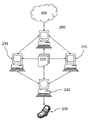
Fig. 2 illustrates sample Virtual Product Development Environment;
Fig. 3 wherein can implement the block scheme of the computer environment of described system;
Fig. 4 a-4b illustrates the universal of the software programming code embodying in software application;
Fig. 5 is the block diagram of the general view of the method that adopts of embodiment;
Fig. 6 illustrates exemplary physical model modification system; And
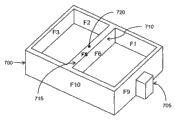
Fig. 7 a-7b illustrates exemplary separation method in solid model modification system.
Embodiment
1. introduce
Described a kind of for revising the method and system of the geometric relationship of solid model.In the following description, for illustrative purposes, many specific detail have been set forth to the thorough understanding to described system is provided.Yet, should it is evident that for a person skilled in the art and can in the situation that there is no these specific detail, implement this system.In other example, with the form of block scheme, well-known structure and equipment are shown to avoid unnecessarily making this system ambiguous hard to understand.
Fig. 2 illustrates sample Virtual Product Development Environment.The current virtual development environment adopting is conventionally from creating product or it in addition improved client requests or intrinsic expectation, generally being illustrated at 200 places.This product can be simple or complicated as submarine as bottle opener.With further reference to Fig. 2, the known method that original designer adopts according to computer-aided design (CAD) (CAD) application program 205 carries out modeling to expected product, on multi-purpose computer, carry out CAD application program 205, described multi-purpose computer becomes subsequently for carrying out in application program and the dedicated computing environment of object computer Computer Aided Design routine when mutual, and its details is below being discussed.CAD application program 205 SolidEdge or NX that preferably Dou You Siemens Production Lifecycle Management software company provides to secure permission.CAD user operates CAD application program 205 in mode well-known and that understood well and is similar to and meets the solid model requiring according to client requests or the definite original design of intrinsic expectation to show virtually.This solid model is generally assembly and a plurality of assembly of parts, and wherein, described a plurality of assemblies are further decomposed into sub-component and/or parts, all preferably has the virtual representation being stored in solid model data file 225 for follow-up re invocation.
Once solid model is confirmed as in requiring consistent appropriate format with original design, preferably by CAE user, use and such as computer-aided engineering (CAE) application program 210 of the NX CAE being provided by Siemens Production Lifecycle Management software company or FEMAP, it is tested, to carry out partial fault-tolerance test and multiple other engineering test.If CAE user determines, must modify successfully pass through tolerating measure to solid model, solid model is returned to CAD user to modify in CAD application program 205.This iteration between CAD application program 205 and CAE application program 210 and each user is recurrence, until solid model is successfully by necessary designing requirement and engineering test.
After being successfully completed, in the solid model with its final design form, also designed to be used the Practical manufacturing in computer-aided manufacturing (CAM) application program 215 of the NX CAM that provides such as Dou You Siemens Production Lifecycle Management software company or CAM Express.By using CAM application program 215, how CAM user will manufacture actual product 230 to numerical control program, mould, instrument and punch die (die) is carried out modeling.CAM user can have additional modifications to meet original design requirement, for example, use electric discharge processing (EDM) may require different technology, depends on whether to use line cutting EDM or die sinking (die sinking) EDM manufactures actual product 230.In order virtually a part to be carried out to milling (mill), 215 definition of CAM application program are for the preferred electrode path of the track of EDM process.CAM user can determine in order to meet design and engine request, and solid model requires trickle modification aspect the size after cooling for example to allow to comprise the sclerosis of the material of actual product 230.
After successful virtual design, through engineering approaches and the manufacture of product, manufacture and economize and all manufacture rules can be linked with the product engineeringization relevant with product, comprising: the production management of the digital plant application program 200 of procedure layout and design, process simulation/through engineering approaches and utilization such as the Tecnomatix being provided by Siemens Production Lifecycle Management software company.Manufacture to economize and may find to improve actual product 230, because CAM user carries out modeling by for example EDM system out-of-date and that require manufacturer to use 5 axle Turing machines (turning machine) to produce necessary base to product, or manufacturer has proceeded to injection molding rather than compression forming forms the part that comprises actual product 230.For example, solid model must be revised as and meet the final requirement of manufacturing actual product 230.
Spread all over above-mentioned VPD, product design for example flows to CAD user to CAE user to CAD user from client requests, is back to CAE user, to CAM user, then to the manufacturer for the actual production of actual product 230.Along with the each editor to solid model, also revise geometric relationship to meet the necessary change in design that for example CAD user, CAE user, CAM user and manufacturer carry out.In addition,, due to each the modification solid model in CAD/CAE/CAM user, the data model of definition solid model is also modified suitably to solve and changes as discussed above and be suitably stored in solid model data file 225.Then, actual product 230 is revised to continue to produce according to original design standard and successive projects by manufacturer.VPD occurs in system, wherein, for revising in the various software application program of the described system and method for the geometric relationship of solid model in can the storer on residing at multiple hardwares system, carries out, and is below described in more detail.
2. computer program
Forward now hardware system to, Fig. 3 wherein can implement the block scheme of the computer system of described system.Fig. 3 and the intention of discussion subsequently provide and wherein can realize the suitable hardware system of the present embodiment and the concise and to the point general remark of computing environment.The present embodiment can be in multiple known calculations environment any middle execution.
With reference to Fig. 3, exemplary computer system comprises the computing equipment of computing machine 300 forms, and such as desk-top computer or laptop computer, it comprises a plurality of associated peripheral (not describing).Computing machine 300 comprises CPU (central processing unit) (CPU) 305 and according to known technology, be used for being connected and can realizing the bus 310 of communication between a plurality of parts of CPU (central processing unit) 305 and computing machine 300.The operation of CPU 350 is thoroughly understood in the art, and it is preferably circuit, can carry out the computer program with the computer executable instructions thereon that is encoded, such as the program module of being carried out by computing machine 300.Conventionally, program module comprises the routine carrying out particular task or realize specific data type, program, object, parts, data structure etc.Preferably, program module comprises document processing module 306, data disaply moudle 307, logic processing module 308 and method processing module 309.Logic processing module 308 sends request to operate according to computer executable instructions to document processing module 306, data disaply moudle 307 and method processing module 309.Similarly, logic processing module receives request to operate according to computer executable instructions from document processing module 306, data disaply moudle 307 and method processing module 309.Bus 310 also makes it possible to realize the communication between various program modules and a plurality of parts.Bus 310 can be any in polytype bus structure, comprises memory bus or Memory Controller, peripheral bus and local bus, and it uses any in multiple bus architecture.Computing machine 300 generally includes CPU (central processing unit) 306 is connected to the user interface adapter 315 such as one or more interfacing equipments of keyboard 320, mouse 325 and/or other interfacing equipment 330 via bus 310, other interfacing equipment 330 can be any user interface facilities, such as touch sensitive screen, digitizing pen tablet etc.Bus 310 is also connected to CPU (central processing unit) 305 via display adapter 340 by the display device such as lcd screen or monitor 335.Bus 310 is also connected to the storer 345 that can comprise ROM, RAM etc. by CPU (central processing unit) 305.
Computing machine 300 also comprises the driving interface 350 that at least one memory device 355 and/or at least one CD-ROM drive 360 is coupled to bus.Memory device 355 can comprise the unshowned hard disk drive for reading and write to it from dish, the unshowned disc driver for reading from removable disk drive or writing to it.Similarly, CD-ROM drive 360 can comprise unshowned CD drive, and it is for the removable disc reading from such as CD ROM or other optical medium or write to it.Aforementioned drives and associated computer-readable media provide computer-readable instruction, data structure, program module and for the non-volatile memories of other data that can be conducted interviews according to the instruction that be received by logic processing module 308 in the described method of the instruction being provided by method processing module 309 by document processing module 306 of computing machine 300.
Computing machine 300 can be via communication channel 365 and other computing machine or computer network communication.Computing machine 300 can be associated with this type of other computing machine in Local Area Network or wide area network (WAN), or it can be the client during the client/server with another computing machine is arranged etc.In addition, can also in distributed computing environment, implement the present embodiment, wherein, by the teleprocessing equipment linking by communication network, carry out the assignment instructions being provided by logic processing module 308 in the described method of the instruction being provided by method processing module 309.In distributed computing environment, program module can be arranged in local and remote memory storage device the two.All these configurations and suitable communication hardware and software are well known in the art.
Forward in more detail now program module to, Fig. 4 a-4b illustrates the universal of the software programming code embodying in software application.With further reference to Fig. 4 a, will program module be described under the background of the present embodiment in more detail below, wherein, software application 400 comprises those addressable program module as discussed above.Software application 400 can be the form of solid modelling application program, such as above-mentioned CAD application program 205, CAE application program 210 or CAM application program 215.In addition can expect by having for access and the specific API(" application programming interface " that utilizes) third-party vendor of calling feature provides software application 400.Continue, along with user and software application 400 interact, some is revised event trigger and interacts with changing modeling tool case (toolkit) 405, and this will discuss in more detail hereinafter.Software application 400 is together with changing modeling tool case 405 or in the described method of the instruction being provided by method processing module 309, utilize individually logic processing module 308 to call rudimentary Geometric Modeling kernel to realize some modification event of solid model according to the order of being selected by user and carried out by software application 400, that as in solid modelling field, understands is such, but discusses in more detail hereinafter.Rudimentary Geometric Modeling kernel be normally similar to the Parasolid being authorized by Siemens Production Lifecycle Management software company at least three-dimensional (3D) Geometric Modeler (modeler) 410 set and 3D DCM(or " DCM " being provided by Siemens Production Lifecycle Management software company is provided) set in how much software part storehouses 415 of product.
On the other hand, with reference to Fig. 4 b, change 405 pairs of variation edit commandss that transmit from software application 400 of modeling tool case and operate.In addition, software application 400 calls (call) by non-variation modeling and is sent to 3D Geometric Modeler 410, and the set in 3D Geometric Modeler 410 how much software part storehouses 415 of utilization, as conventionally understood in Geometric Modeler field.About changing modeling tool case 405 and below by what discuss in more detail, occur and relate to the variation of searching, edit, solving and apply and edit relevant a plurality of operations.The set that is generally understood that above how much software part storehouses in solid modelling field provides modeling function, for example, such as Geometric Constraint Solving, variation design, parameter designing, motion simulation, collision detection, gap calculating, topological structure position, topological structure mobility solution and hidden line, eliminate.It is also contemplated that in the scope of the present embodiment, 3D Geometric Modeler 410 and part library 415 are the parts of same application rather than independent parts or its combination.Described computer program, the more details about piece-rate system are provided now.
3. piece-rate system
Forward now face piece-rate system to, Fig. 5 is the block diagram of the general view of the method that adopts of the present embodiment.With reference to Fig. 5, the present embodiment discloses the logic processing module 308 that the described method of instruction being provided by method processing module 309 is provided, wherein, described method is the method for separating of the face in the solid model of handling at the computing machine with the software instruction for designing, and generally at 500 places, describes.To mention following steps and be in order to provide in the general survey with the embodiment described in the system of details of subsequent discussion.This system is used computer peripheral input end directly on solid model, to select to revise the selected element (step 500) in feature.This system will be adjacent to a plurality of adjacent surface classification (step 505) of the selection face of being determined by selected element by distance.This system determines whether to exist wherein said a plurality of adjacent surface to the protruding situation (step 510) of selection face projection.This system determines whether to exist wherein said a plurality of adjacent surface and previously accessed face to share same surface and has candidate's curve (step 515) of described protruding situation.This system is marked at candidate's curve on solid model and is intended to modify (step 520) so that solid model is ready for according to the modification from user.This system is according to causing the modification of revising solid model and having revised visible demonstration information to be intended to revise solid model (step 525).This system shows and has revised solid model (step 530) to user with revising visible demonstration information.
Fig. 6 illustrates exemplary physical model modification system.Necessity order that user's execution of use software application 400 is used for software application 400 is to access the preferably memory device 355 of hard disk drive 600, hard disk drive 600 has the data relevant with the virtual representation that is stored in the solid model in solid model data file 425, and described solid model data file 425 preferably can be by software application 400, variation modeling tool case 405,3D Geometric Modeler 410 and part library 415 access.With further reference to Fig. 6, software application 400 is characterised in that solid modelling application program 605, its access is preferably constructed to preferably to indicate stand.x_t form, indication for the modeling device transfer files type of 3D Geometric Modeler 410 to be stored in the solid model data file 425 of the data file 610 on hard disk drive 600 for changing the stand.vtk_data form of the variation modeling tool case message file type of modeling tool case 405, wherein, stand* refers to generic part filename.Solid modelling application program 605 has its oneself identification file type extension, APP for example, and it has been identified file type extension with this and has obtained for handling the enough information of solid model.Continue, solid modelling application program 605 is loaded into stand.x_t file by the 3D Geometric Modeler session main body of being accessed by 3D Geometric Modeler 410.Stand.vtk_data file is loaded and adds 3D Geometric Modeler session main body to.Solid modelling application program 605 load about the application data of solid model and according to its oneself file type for example PRT visit data file 610.The deviser who has loaded solid model is intended to revise certain aspect of the solid model of seeing.When this is intended to, deviser's selection can be that the topological structure on face, limit or summit is modified.By selecting topological structure to modify, solid modelling application program starts to interact by means of changing modeling tool case API 615, to process modification calculating by technology as known in the art with variation modeling tool case 405.After solid model is revised, in order to be saved in hard disk drive 600 by revising solid model, piece 620 illustrates the data relevant with changing modeling tool case 405 and is deleted (striped) and be placed into vtk_data data structure from solid model, and described vtk_data data structure is saved to stand.vtk_data file subsequently.Deleted entity body is also saved to hard disk drive 600, as application data.Discuss in more detail below and select for example action of the topological structure of merged rib.
4. separation method
Forward in more detail now face piece-rate system to, this system comprises the face separation method that adopts traversal recursive program multipass, and described recursive program has single and selected element as input.Keep set C to select merged rib to be added to the supplemental characteristic on all new limits of model afterwards to be stored in.The method also keeps by the one group of face F (e) getting rid of from processing, and wherein, list is empty at first.The current state of solid model is stored in S.The method is with single the input with the form reception deviser of selected element.Obtain the adjacent surface of described single and classify by distance.With recursive fashion, check the adjacent surface of classifying and obtaining to determine the potentiality (potential) of rib qualification and restriction rib by separation.For rib qualification, adjacent surface must be with respect to single projection of input.For the potentiality restriction of rib, carry out two and determine.First, if adjacent surface and previously accessed face are shared identical surface and next, if any two masks have and the peripheral loop that was previously identified as the face adjacency of rib, described method is attempted face separation.In addition, if add limit, stop recurrence and use initial input to carry out another time, wherein, these faces are got rid of from any further processing.This second definite scope effectively reducing at all follow-up faces all over middle access, for example, the same face may be more than once separated, therefore can have multipass.The parameter that is used for the limit of all generations is stored in set C.When exhausting (exhausting) this group adjacent surface, recursively access the above-mentioned face that meets rib qualification, until no longer include the face that will access.Now, from set C, abandon the supplemental characteristic on those limits on the border of single of not limiting input.Solid model is returned to the state S of preservation, and the limit being kept in set C is tagged in solid model.
5. separated explanation
Fig. 7 a-7b illustrates exemplary separation in solid model modification system.With reference to Fig. 7 a and 7b, deviser has loaded solid model 700 for revising to show as seen.Solid model 700 has rib 705 and merged rib 710.Deviser is intended to revise merged rib 710 and determines selection face 715 and selected element 720.It is selected of a PT place that system makes FS.F1 and F2 share same surface and both are all adjacent to FS, therefore can carry out parting plane FS with this lip-deep curve.When initialization, system F (e) and C are set to equal empty set { }."current" model state is saved as S.In this example, occur 3 times.At the 1st time,

From foregoing, it is evident that adjacent surface F5 and F6 will not join rib, so recurrence finishes to be defined also segregate rib.Forward now model state S to, and mark curve C 1 and C2 are as a part for solid model 800.
6. conclusion
The present embodiment can be realized in Fundamental Digital Circuit or in computer hardware, firmware, software or in its combination.The device of the present embodiment can be realized at the computer program for being carried out by programmable processor visibly embodying in machine readable storage device; And the method step of the present embodiment can be by coming execution of programs of instructions to carry out to carry out the programmable processor of the function of the present embodiment by input data being operated and generated output.
The present embodiment can advantageously be realized in the one or more computer programs that can carry out on programmable system, and described programmable system comprises being coupled from data-storage system and receives data and instruction and send at least one programmable processor, data-storage system, at least one input equipment and at least one output device of data and instruction to it.If described application program can or be expected to realize with compilation or machine language with advanced procedures or OO programming language; And under any circumstance, described language can be compiling or interpretative code.
Conventionally, processor will receive instruction and data from ROM (read-only memory) and/or random access memory.The memory device that is suitable for visibly embodying computer program instructions and data comprises and comprises for example semiconductor memory devices, such as EPROM, EEPROM and flash memory device by the nonvolatile memory of many forms; Disk, such as internal hard drive and removable dish; Magneto-optic disk; And CD-ROM dish.Aforesaid any one can be by custom-designed ASIC(special IC) supplement or be attached to wherein.
Many embodiment have been described.Be understood that in the situation that do not depart from the spirit and scope of the present embodiment and carry out various modifications.Can expect that disclosed active selective system is for also will be effectively such as the situation such as coplanar, coaxial, because it utilizes feature.Therefore, other is realized in the scope of following claim.
Claims (8)
1. for separating of a method for the face in solid model (700), comprise step:
I) use the directly selected element (720) on the upper selection face (715) of solid model (700) of computer peripheral input end (325);
Ii) by distance, will be adjacent to a plurality of adjacent surfaces (F1, the F2 by the definite selection face (715) of selected element (720); F3, F4, F5, F6, F7, F8) classification;
Iii) determine whether to exist wherein said a plurality of adjacent surface (F1, F2; F3, F4, F5, F6, F7, F8) to the protruding protruding situation of described selection face (715);
Iv) determine whether to exist wherein said a plurality of adjacent surfaces (F1, F2) and previously accessed face to share same surface and have candidate's curve of described protruding situation;
V) candidate's curve is marked to solid model (700) is upper so that solid model (700) is ready for according to the modification intention (200) from user modifies;
Vi) according to the described modification that causes revising solid model (200) and revised visible demonstration information, be intended to (200) and revise solid model (700); And
Vii) with revising visible demonstration information, revised solid model described in showing to user.
2. according to the process of claim 1 wherein that step I ii) carries out by recursive program.
3. according to the method for claim 1 or claim 2, also comprise the solid model data file (610) with visible demonstration data is loaded in solid model modeled applications.
4. according to the method for claim 1, also comprise the described solid model of having revised is calculated in described solid model data file (225).
5. for separating of an equipment for the face in solid model (700), comprising:
I) for using the directly device of the selected element (720) on the upper selection face (715) of solid model (700) of computer peripheral input end (325);
Ii) for being adjacent to a plurality of adjacent surfaces (F1, the F2 by the definite selection face (715) of selected element (720) by distance; F3, F4, F5, F6, F7, F8) device of classification;
Iii) for determining whether to exist wherein said a plurality of adjacent surface (F1, F2; F3, F4, F5, F6, F7, F8) to the device of the protruding situation of described selection face (715) projection;
Iv) for determining whether to exist wherein said a plurality of adjacent surfaces (F1, F2) and previously accessed face to share same surface and having the device of candidate's curve of described protruding situation;
V) for candidate's curve is marked at, solid model (700) is upper so that solid model (700) is ready for the device of modifying according to the modification intention (200) from user;
Vi) for being intended to (200) according to the described modification that causes revising solid model (200) and revised visible demonstration information, revise the device of solid model (700); And
Vii) for the device with having revised visible demonstration information and revised described in showing to user solid model.
6. according to the equipment of claim 5, wherein determine whether to exist wherein said a plurality of adjacent surface (F1, F2; F3, F4, F5, F6, F7, F8) to the device of the protruding protruding situation of described selection face (715), by recursive program, carry out.
7. according to the equipment of claim 5 or claim 6, also comprise for the solid model data file (610) with visible demonstration data being loaded into the device of solid model modeled applications.
8. according to the equipment of claim 5, also comprise for having revised by described the device that solid model calculates described solid model data file (225).
Applications Claiming Priority (5)
| Application Number | Priority Date | Filing Date | Title |
|---|---|---|---|
| US4464408P | 2008-04-14 | 2008-04-14 | |
| US61/044644 | 2008-04-14 | ||
| US12/422350 | 2009-04-13 | ||
| US12/422,350 US8872820B2 (en) | 2008-04-14 | 2009-04-13 | System and method for splitting faces on a solid model |
| PCT/US2009/002307 WO2009128897A1 (en) | 2008-04-14 | 2009-04-14 | System and method for splitting faces on a solid model |
Publications (2)
| Publication Number | Publication Date |
|---|---|
| CN102067133A CN102067133A (en) | 2011-05-18 |
| CN102067133B true CN102067133B (en) | 2014-04-30 |
Family
ID=41163613
Family Applications (1)
| Application Number | Title | Priority Date | Filing Date |
|---|---|---|---|
| CN200980122294.2A Active CN102067133B (en) | 2008-04-14 | 2009-04-14 | System and method for splitting faces on a solid model |
Country Status (5)
| Country | Link |
|---|---|
| US (1) | US8872820B2 (en) |
| EP (1) | EP2281254A1 (en) |
| JP (1) | JP5474045B2 (en) |
| CN (1) | CN102067133B (en) |
| WO (1) | WO2009128897A1 (en) |
Cited By (1)
| Publication number | Priority date | Publication date | Assignee | Title |
|---|---|---|---|---|
| CN106415554A (en) * | 2014-06-03 | 2017-02-15 | 西门子产品生命周期管理软件公司 | Aerospace joggle on multiple adjacent web faces with intersecting runouts |
Families Citing this family (10)
| Publication number | Priority date | Publication date | Assignee | Title |
|---|---|---|---|---|
| US20150278401A1 (en) * | 2014-03-28 | 2015-10-01 | Siemens Product Lifecycle Management Software Inc. | Intelligent offset recognition in cad models |
| US20160328496A1 (en) * | 2015-05-04 | 2016-11-10 | Siemens Product Lifecycle Management Software Inc. | System and method for editing a model |
| US10360312B2 (en) | 2015-05-04 | 2019-07-23 | Siemens Product Lifecycle Management Software Inc. | System and method for identifying clones |
| CN107256004B (en) * | 2017-06-29 | 2020-06-09 | 歌尔股份有限公司 | Product processing method and device |
| US11321605B2 (en) * | 2017-11-13 | 2022-05-03 | Dassault Systemes Solidworks Corporation | Automatic assembly mate creation for frequently-used components |
| CN110213205B (en) * | 2018-03-27 | 2021-08-24 | 腾讯科技(深圳)有限公司 | Verification method, device and equipment |
| EP3690682A1 (en) * | 2019-02-01 | 2020-08-05 | Dassault Systèmes | Designing a part featuring a protrusion or a depression |
| EP3761211A1 (en) | 2019-07-04 | 2021-01-06 | Dassault Systèmes | Designing a part featuring a bump |
| US20230302748A1 (en) * | 2020-09-22 | 2023-09-28 | Hewlett-Packard Development Company, L.P. | Pore placement determinations using anchor points |
| CN113283017A (en) * | 2021-06-25 | 2021-08-20 | 宝能(广州)汽车研究院有限公司 | Part separation method, device, equipment and storage medium |
Citations (3)
| Publication number | Priority date | Publication date | Assignee | Title |
|---|---|---|---|---|
| US6629065B1 (en) * | 1998-09-30 | 2003-09-30 | Wisconsin Alumni Research Foundation | Methods and apparata for rapid computer-aided design of objects in virtual reality and other environments |
| US7042451B2 (en) * | 2002-04-19 | 2006-05-09 | Geometric Software Solutions Co., Limited | Methods using specific attributes and graph grammars in graph-based techniques for feature recognition |
| CN1869993A (en) * | 2005-04-08 | 2006-11-29 | 达索系统公司 | Method of computer-aided design of a modeled object having several faces |
Family Cites Families (4)
| Publication number | Priority date | Publication date | Assignee | Title |
|---|---|---|---|---|
| JP3513562B2 (en) | 2000-04-20 | 2004-03-31 | インターナショナル・ビジネス・マシーンズ・コーポレーション | Shape analysis system, three-dimensional shape model difference detection system, similar shape search system, shape analysis method, and storage medium |
| US7313504B2 (en) * | 2001-10-15 | 2007-12-25 | Solidworks Corporation | Model management technology using grouping of features |
| JP4364520B2 (en) | 2003-01-29 | 2009-11-18 | 富士通株式会社 | Three-dimensional sheet metal model creation method and computer program |
| JP4472642B2 (en) | 2005-01-26 | 2010-06-02 | ダッソー システムズ ソリッドワークス コーポレイション | Recognition and active features for computer-aided design systems |
-
2009
- 2009-04-13 US US12/422,350 patent/US8872820B2/en active Active
- 2009-04-14 JP JP2011505011A patent/JP5474045B2/en active Active
- 2009-04-14 CN CN200980122294.2A patent/CN102067133B/en active Active
- 2009-04-14 WO PCT/US2009/002307 patent/WO2009128897A1/en active Application Filing
- 2009-04-14 EP EP09732090A patent/EP2281254A1/en not_active Withdrawn
Patent Citations (3)
| Publication number | Priority date | Publication date | Assignee | Title |
|---|---|---|---|---|
| US6629065B1 (en) * | 1998-09-30 | 2003-09-30 | Wisconsin Alumni Research Foundation | Methods and apparata for rapid computer-aided design of objects in virtual reality and other environments |
| US7042451B2 (en) * | 2002-04-19 | 2006-05-09 | Geometric Software Solutions Co., Limited | Methods using specific attributes and graph grammars in graph-based techniques for feature recognition |
| CN1869993A (en) * | 2005-04-08 | 2006-11-29 | 达索系统公司 | Method of computer-aided design of a modeled object having several faces |
Cited By (2)
| Publication number | Priority date | Publication date | Assignee | Title |
|---|---|---|---|---|
| CN106415554A (en) * | 2014-06-03 | 2017-02-15 | 西门子产品生命周期管理软件公司 | Aerospace joggle on multiple adjacent web faces with intersecting runouts |
| CN106415554B (en) * | 2014-06-03 | 2021-06-11 | 西门子工业软件公司 | Aeronautical rocking on multiple adjacent web faces with intersecting jumps |
Also Published As
| Publication number | Publication date |
|---|---|
| US8872820B2 (en) | 2014-10-28 |
| EP2281254A1 (en) | 2011-02-09 |
| JP5474045B2 (en) | 2014-04-16 |
| CN102067133A (en) | 2011-05-18 |
| WO2009128897A1 (en) | 2009-10-22 |
| JP2011517000A (en) | 2011-05-26 |
| US20090256842A1 (en) | 2009-10-15 |
Similar Documents
| Publication | Publication Date | Title |
|---|---|---|
| CN102067133B (en) | System and method for splitting faces on a solid model | |
| CN102067130B (en) | System and method for modifying geometric relationships in solid model | |
| CN102067131B (en) | System and method for converting dimensions | |
| CN102053829B (en) | For the method and system of design object assembly in computer aided design system | |
| KR101855736B1 (en) | Designing a modeled object within a session of a computer-aided design system interacting with a database | |
| CN102067132A (en) | System and method for modifying features in a solid model | |
| US20180181682A1 (en) | Replica selection | |
| US9798835B2 (en) | Groups of faces that form a geometrical pattern | |
| US9904524B2 (en) | Method and device for visually implementing software code | |
| CN102073499A (en) | Method and system for designing an assembly of objects in a system of computer-aided design | |
| CN103093036A (en) | Simulation of the machining of a workpiece | |
| CN102779202B (en) | Method and apparatus for the executor of selecting object | |
| CN102831636A (en) | Designing a three-dimensional modeled assembly of objects in a three-dimensional scene | |
| CN102067134B (en) | System and method for active selection in a solid model | |
| US11275870B2 (en) | Designing an assembly of parts in a three-dimensional scene | |
| US11960794B2 (en) | Seamless three-dimensional design collaboration | |
| CN104965938A (en) | Designing industrial products by using geometries connected by geometrical constraints | |
| CN114283441B (en) | Two-dimensional drawing recognition modeling method and device suitable for railway passenger station | |
| Lu et al. | Plastic Product Evaluation Based on Mold Conceptual Design |
Legal Events
| Date | Code | Title | Description |
|---|---|---|---|
| C06 | Publication | ||
| PB01 | Publication | ||
| C10 | Entry into substantive examination | ||
| SE01 | Entry into force of request for substantive examination | ||
| C14 | Grant of patent or utility model | ||
| GR01 | Patent grant | ||
| CP01 | Change in the name or title of a patent holder | ||
| CP01 | Change in the name or title of a patent holder |
Address after: American Texas Patentee after: SIEMENS INDUSTRY SOFTWARE N.V. Address before: American Texas Patentee before: SIEMENS PRODUCT LIFECYCLE MANAGEMENT SOFTWARE Inc. |