CN102067131B - System and method for converting dimensions - Google Patents
System and method for converting dimensions Download PDFInfo
- Publication number
- CN102067131B CN102067131B CN200980122291.9A CN200980122291A CN102067131B CN 102067131 B CN102067131 B CN 102067131B CN 200980122291 A CN200980122291 A CN 200980122291A CN 102067131 B CN102067131 B CN 102067131B
- Authority
- CN
- China
- Prior art keywords
- father
- layer
- geometry
- sketch
- dac
- Prior art date
- Legal status (The legal status is an assumption and is not a legal conclusion. Google has not performed a legal analysis and makes no representation as to the accuracy of the status listed.)
- Expired - Fee Related
Links
Images


Classifications
-
- G—PHYSICS
- G06—COMPUTING; CALCULATING OR COUNTING
- G06F—ELECTRIC DIGITAL DATA PROCESSING
- G06F30/00—Computer-aided design [CAD]
-
- G—PHYSICS
- G06—COMPUTING; CALCULATING OR COUNTING
- G06F—ELECTRIC DIGITAL DATA PROCESSING
- G06F2111/00—Details relating to CAD techniques
- G06F2111/04—Constraint-based CAD
Abstract
A system, method, and computer program for selecting geometries from a solid model that is manipulated in a computer having software instructions, comprising: a computer system, wherein the computer system includes a memory, a processor, a user input device, and a display device; a computer generated geometric model stored in the memory of the computer system; and wherein the computer system selects a two-dimensional sketch geometry from a two-dimensional sketch to form a three-dimensional model using a feature command; identifies a plurality of elements on the two-dimensional sketch geometry that correspond to the three-dimensional model; forms a counterpart element on the three-dimensional model that is one of a dimension and a constraint from the identified plurality of elements; and provides the capability to modify the three-dimensional model by manipulating the counterpart element; and appropriate means and computer-readable instructions.
Description
the cross reference of related application
The application requires the right of priority of the co-pending interim US application serial No. 61/044,620 of submitting on April 14th, 2008.
Technical field
The system of innovation as herein described relates generally to computer aided design software application.More specifically, this system relates to for converting two-dimensional to three-dimensional dimension.
Background technology
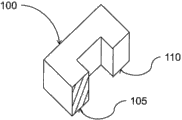
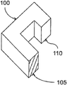
In the field of current computer-aided design (CAD) (CAD) application and geometry modeling system, conventionally with the one in following two kinds of modes, carry out design elements: based on history or without history.System based on historical is usually take the parameter model example in the mid-80 appearance of 20th century as feature.In parameter model system, create method for making (recipe) or historical tree to reflect how things is relative to each other.When an original project is modified, all items producing from this original project in the time is after a while updated.Like this, for example, two faces can keep coplanar because these two faces be used in catch during design process and during renewal process simply this type of relation of " playback " design.Fig. 1 a-1c illustrates the trimetric projection of three-dimensional block.With reference to figure 1a, the C block 100 of three-dimensional (" 3D ") can be watched and need to both modify by changing bottom leg 105, top leg 110 or bottom leg 105 and top leg 110 by user for user on graphoscope.In the system based on historical, user have many easily revise C block 100 depend on this C block 100 at first CAD application system-such as the SolidEdge of Siemens Product Lifecycle Management Software company-in how to be designed.Conventionally, original designer creates and/or design is modified the part that deviser revises after a while, and this modification deviser may be unfamiliar with completely to original designer.For example, if original designer, that people of initial design C block 100 has the face relevant with top leg 110 with bottom leg 105 is constrained to coplanar method for designing intention, if not the object for simple declaration, in the modification action of Fig. 1 c illustrated, be easy to use the modeling technique of known parameters basic for the technician in 3D modelling field/based on historical to realize, because it is coplanar that two faces are confined to, a mobile face will impel another side also to move.If on the other hand, revise deviser's intention and when leaving separately top leg 110, only move the face being associated with bottom leg 105, for example Fig. 1 b, must there are some additional steps to remove coplanar constraint, this requires some additional steps, if from understanding modification deviser is not original designer, two supporting legs that so how to create C block 100.In addition, if the original designer of C block 100 is not modeled as coplanar by bottom leg 105 and top leg 110, but use such as other method of distance or formula, supporting leg is carried out to modeling, as seen in Fig. 1 c, improve both and will difficulty be increased to revise deviser's degree that C block 100 is carried out to modeling that also can start anew.
On the other hand, by the company that is similar to for example CoCreate, IronCAD and Kubotek, taked without historical or method based on main body in revise C block 100 and fail to keep the history of being popularized by parameter model example to set.In without historical approach, clearly the each project on solid model is changed.If the original designer of C block 100 intention is the face in bottom leg 105 and top leg 110 and keeps coplanar relation, the result of the manual selection that modification after a while requires the face for editing to guarantee to expect, if being intended that of original designer is unknown or unascertainable, this is difficult.For example, revising deviser may be only by selecting a face or selecting individually all other coplanar faces to carry out the variation shown in Fig. 1 b or Fig. 1 c, and this is minority in this example by chance, but in complex assemblies model, can have hundreds of.Alternatively, some software application can allow to revise deviser's " make multiple coplanar " and permanently catch design idea after editor, but this may be also loaded down with trivial details, particularly the in the situation that of very large model.This rear a kind of alternative is by the modification difficulty of seeing in Fig. 1 b that makes to carry out in the future, particularly because present design idea may be baked in the model contrary with design idea.
The problem existing based on historical method is combination fixing design idea when model creation, and this may make the unexpected change of carrying out after a while when model creation become complicated.On the contrary, without legacy system, aspect variation in the future, be flexibly, but capturing the very little information of how to be correlated with about things.If modification deviser determines at time point after a while, manually catch this type of information, be similar to the system based on historical, this information is combined and fixing, thereby limits further dirigibility.
That is to say, although without legacy system owing to can be after model creation adding " driving size " and more flexible to solid model, from the size of two-dimentional sketch, can not be transferred to 3D solid model.Driving size is to allow deviser to be caused and revised or replace the size of management design more accurately by the numerical value based on being identified by size.
The inventor advantageously recognizes the needs for size is moved to the system and method for solid model from 2D sketch model.
Summary of the invention
In order to solve identified needs and relevant issues, a kind of system provides a kind of solid model operating in the computing machine with software instruction that is used to select the system of revising, comprise: computer system, wherein said computer system comprises storer, processor, user input device and display device; Be stored in the geometric model that the computing machine in the storer of described computer system generates; And wherein said computer system selects two-dimentional sketch geometry to form three-dimensional model by characteristic commands from two-dimentional sketch; Identify the multiple elements corresponding with three-dimensional model on two-dimentional sketch; On three-dimensional model, form the reciprocity element as one of the size from identified multiple elements and constraint; And provide by operating the first ability of usually revising three-dimensional model of described equity.
The further feature of system is partly set forth in following explanation and accompanying drawing, and partly acquistion from the enforcement of system.Referring now to the following drawings that forms a described system part, described system is described.Should be understood that and can utilize other embodiment, and can modify the in the situation that of detachment system scope not.
Accompanying drawing explanation
In connection with accompanying drawing, carry out descriptive system hereinafter, wherein identical sign represents identical element.
Fig. 1 a-1c illustrates the trimetric projection of three-dimensional block.
Fig. 2 illustrates sample Virtual Product Development Environment.
Fig. 3 is the block scheme that wherein can implement the computer environment of native system.
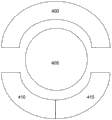
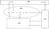
Fig. 4 a-4b illustrates the universal of the software programming code embodying in software application.
Fig. 5 is the block scheme of the general view of the method that adopts of embodiment.
Fig. 6 illustrates exemplary physical model modification system.
Fig. 7 a-7b illustrates the realization of size method.
Embodiment
1. introduce
The method and system of the geometric relationship for revising solid model is described.In the following description, for illustrative purposes, many specific detail have been set forth to the thorough understanding to system is provided.But, it is evident that for a person skilled in the art and can in the situation that there is no these specific detail, implement native system.In other example, with the form of block scheme, illustrate that well-known structure and equipment are to avoid unnecessarily making this system ambiguous hard to understand.
Fig. 2 illustrates sample Virtual Product Development Environment.Current adopted virtual development environment is conventionally from creating product or it in addition improved client requests or intrinsic expectation, usually being illustrated at 200 places.This product can be simple or complicated as submarine as bottle opener.With further reference to Fig. 2, original designer is carried out modeling according to computer-aided design (CAD) (CAD) application 205 known methods that adopt to expected product.On multi-purpose computer, carry out CAD application program 205, described multi-purpose computer becomes the dedicated computing environment for object computer Computer Aided Design routine when application is carried out and be mutual subsequently, and its details is below being discussed.205 SolidEdge or the NX that preferably provided to secure permission by Siemens Product Lifecycle Management Software company are provided CAD.CAD user operates CAD application 205 in mode well-known and that understood well and is similar to and meets the solid model requiring according to client requests or the definite original design of intrinsic expectation to show virtually.This solid model is generally the assembly of assembly and parts, and wherein these assemblies are further decomposed into sub-component and/or subassembly, all preferably has and is stored in the virtual representation for follow-up re invocation in solid model data file 225.
Once solid model is confirmed as taking requiring consistent appropriate format with original design, preferably by CAE user, use such as computer-aided engineering (CAE) application 210 of the NX CAE being provided by Siemens Product Lifecycle Management Software company or FEMAP it is tested, to carry out partial fault-tolerance test and multiple other engineering test.If CAE user determines, must modify successfully pass through tolerating measure to solid model, solid model is returned to CAD user to modify in CAD application 205.This iteration between CAD application 205 and CAE application 210 and each user is recurrence, until solid model is successfully by necessary designing requirement and engineering test.
After being successfully completed, the solid model of final design form also designed to be used such as the physics manufacture in computer-aided manufacturing (CAM) application 215 of the NX CAM being provided by Siemens Product Lifecycle Management Software company or CAM Express.By using CAM application 215, CAM user how to manufacture actual product 230 to numerical control program, mould, instrument and punch die, carry out modeling.CAM user can carry out additional modifications to meet original design requirement, and for example using electric discharge processing (EDM) may basis be with line cutting EDM or die sinking EDM, to manufacture actual product 230 to carry out the different technology of requirement.In order virtually part to be carried out to milling, CAM application 215 definition are for the preferred electrode path of the track of EDM process.CAM user can determine: in order to meet design and engine request, solid model requires the trickle modification of size aspect, for example after cooling to allow the sclerosis of the material that comprises actual product 230.
After successful virtual design, research and development and the manufacture of product, manufacturer can link all manufactures rule with the research and development of products relevant with product, comprising: procedure layout and design, process simulation/research and development and utilize digital plant apply 200-such as the Tecnomatix being provided by Siemens Product Lifecycle Management Software company-production management.Manufacturer may find to improve actual product 230, because CAM user carries out modeling by for example EDM system out-of-date and that require manufacturer's 5 shaft lathes to produce necessary base to product, or manufacturer has proceeded to injection mo(u)lding rather than compression forming forms the part that comprises actual product 230.For example, solid model must be revised as and meet the final requirement of manufacturing actual product 230.
Spread all over above-mentioned VPD, product design for example flows to CAD user to CAE user to CAD user from client requests, is back to CAE user, to CAM user, then to the manufacturer for the actual production of actual product 230.Along with the each editor to solid model, also revise geometric relationship to meet the necessary change in design that for example CAD user, CAE user, CAM user and manufacturer carry out.In addition,, due to each the modification solid model in CAD/CAE/CAM user, the data model of definition solid model is also modified suitably to solve and changes as discussed above and be suitably stored in solid model data file 225.Then, actual product 230 is revised to continue to produce according to original design specification and successive projects by manufacturer.VPD occurs in system, wherein for the described system and method for the geometric relationship of revising solid model, can carry out in the various software application that is arranged in the storer in multiple hardwares system, is below described in more detail.
2. computer program
Forward now hardware system to, Fig. 3 is the block scheme that wherein can implement the computer system of described system.Fig. 3 and the intention of discussion subsequently provide and wherein can realize the suitable hardware system of the present embodiment and the concise and to the point general remark of computing environment.The present embodiment can be in multiple known calculations environment any middle execution.
With reference to figure 3, exemplary computer system comprises the computing equipment of taking computing machine 300 forms, and such as desk-top computer or laptop computer, described computing equipment comprises multiple associated peripheral (not describing).Computing machine 300 comprises CPU (central processing unit) (CPU) 305 and is used for connecting and makes it possible to realize the bus of communicating by letter 310 between CPU (central processing unit) 305 and multiple parts of computing machine 300 according to known technology.The operation of CPU 350 is thoroughly understood in the art, and this CPU 350 is preferably circuit, and this circuit can be carried out the computer program with the superincumbent computer-readable instruction that is encoded, such as the program module of being carried out by computing machine 300.Conventionally, program module comprises the routine, program, object, parts, data structure etc. carrying out particular task or realize specific data type.Preferably, program module comprises document processing module 306, data disaply moudle 307, logic processing module 308 and method processing module 309.Logic processing module 308 sends request to operate according to computer executable instructions to document processing module 306, data display module 307 and method processing module 309.Similarly, logic processing module receives request to operate according to computer executable instructions from document processing module 306, data display module 307 and method processing module 309.Bus 310 also makes it possible to realize the communication between various program modules and multiple parts.Bus 310 can be any in the bus structure of some types, comprises any memory bus or Memory Controller, peripheral bus and the local bus that use in multiple bus architecture.Computing machine 300 generally includes CPU (central processing unit) 306 is connected to the user interface adapter 315 such as one or more interfacing equipments of keyboard 320, mouse 325 and/or other interfacing equipment 330 via bus 310, other interfacing equipment 330 can be any user interface facilities, such as touch-screen, digitizing writing pencil tablet etc.Bus 310 also will be connected to CPU (central processing unit) 305 such as the display device 335 of LCD screen or monitor via display adapter 340.Bus 310 is also connected to the storer 345 that can comprise ROM, RAM etc. by CPU (central processing unit) 305.
Forward in more detail now program module to, Fig. 4 a~4b illustrates the universal of the software programming code embodying in software application.With further reference to Fig. 4 a, will program module be described under the background of the present embodiment in more detail below, wherein software application 400 comprises those addressable program modules as discussed above.Software application 400 can be the form of solid modelling application, such as above-mentioned CAD application 205, CAE application 210 or CAM application 215.In addition, can expect and provide and have for access and the specific API(" application programming interface " that utilizes by third-party vendor) call the software application 400 of feature.Unceasingly, along with user and software application 400 interact, the modeling tool case 405 of specific modification event trigger and variation interacts, and this will be described in more detail below.Software application 400 is together with changing modeling tool case 405 or in the described method of the instruction being provided by method processing module 309, utilize individually logic processing module 308 to call low-level Geometric Modeling core to realize the specific modification event of solid model according to the order of being selected by user and carried out by software application 400, that as in solid modelling field, understands is such, and discusses in more detail hereinafter.Low-level Geometric Modeling core is normally similar to the set in how much software part storehouses 415 of 2D that the set and being similar to of at least three-dimensional (3D) Geometric Modeling instrument 410 of the Parasolid being authorized by Siemens Product Lifecycle Management Software company provides by Siemens Product Lifecycle Management Software company or 3D dimension constraint manager (or " DCM ") product.
On the other hand, with reference to figure 4b, change modeling tool case 405 the variation edit commands transmitting from software application 400 is operated.In addition, software application 400 is called out non-variation modeling to be sent to 3D Geometric Modeling instrument 410, and the set in 3D Geometric Modeling instrument 410 how much software part storehouses 415 of utilization, as conventionally understood in Geometric Modeling field of tool.About changing modeling tool case 405 and below by what discuss in more detail, occur and relate to the variation of searching, edit, solving and applying and edit relevant multiple operations.The set that is generally understood that above how much software part storehouses in solid modelling field provides modeling function, such as Geometric Constraint Solving, variation design, parameter designing, motion simulation, collision detection, clearance calculating, topological structure position, topological structure, moves and decomposes and hidden line elimination.It is also contemplated that in the scope of the present embodiment, 3D Geometric Modeling instrument 410 and part library 415 are the parts of same application rather than independent assembly or its combination.Describe computer program, about piece-rate system, provide more details now.
3. size system
Forward now face piece-rate system to, Fig. 5 is the block diagram of the general view of the method that adopts of the present embodiment.With reference to figure 5, the present embodiment discloses the logic processing module 308 that the described method of instruction being provided by method processing module 309 is provided, wherein said method is the method that the solid model for handling at the computing machine with the software instruction for designing designs, and usually with 500, describes.Following steps are mentioned to provide in the general survey with the embodiment described in the system of details of subsequent discussion.System selects two-dimentional sketch geometry to form three-dimensional model by characteristic commands from two-dimentional sketch.Multiple elements (step 505) on the system identification two-dimentional sketch corresponding with three-dimensional model.System forms reciprocity element on three-dimensional model, and this equity element is (step 510) intrafascicular from the size peace treaty of identified multiple elements.This system provides the ability (step 515) of usually revising three-dimensional model by operating equity unit.
Fig. 6 illustrates exemplary physical model modification system.Use the user of software application 400 to carry out necessity order that is used for software application 400 to access the preferably memory device 355 of hard disk drive 600, hard disk drive 600 has the data relevant with being stored in virtual representation in solid model data file 425, and described solid model data file 425 preferably can be by software application 400, change modeling tool case 405,3D Geometric Modeling instrument 410 and part library 415 access.With further reference to Fig. 6, software application 400 is characterised in that the solid modelling application 605 of access entity model data file 425, this solid model data file 425 is preferably constructed to preferably for the stand.x_t form of the modeling tool Transmit message type of 3D Geometric Modeling instrument 410, indication, for the stand.vtk_data form of the variation modeling tool case message file type that changes modeling tool case 405, to be stored in the data file 610 on hard disk drive 600 with indication, wherein, stand* refers to generic document name.Solid modelling application 605 has its own identification file type extension, for example APP, and this solid modelling is applied 605 use, and this has been identified file type extension and has obtained the enough information for handling solid model.Unceasingly, solid modelling application 605 is loaded into stand.x_t file by the 3D Geometric Modeling instrument session main body of being accessed by 3D Geometric Modeling instrument 410.Stand.vtk_data file is loaded and is added to 3D Geometric Modeling instrument session main body.Solid modelling application 605 loads the application data relevant with solid model and for example, visits data file 610 according to its oneself file type (PRT).
The deviser of the solid model having loaded is intended to revise certain aspect of the solid model of seeing.When planning like this, deviser's selection can be that the topological structure on face, limit or summit is modified.By selecting topological structure to modify, solid modelling is applied beginning and is interacted by means of changing modeling tool case API 615, to process modification calculating by technology as known in the art with variation modeling tool case 405.After solid model is revised, in order to be kept at hard disk drive 600 by revising solid model, square frame 620 illustrates the data relevant with changing modeling tool case 405 of being removed and being placed into from solid model vtk_data data structure, and described vtk_data data structure is saved to stand.vtk_data file subsequently.The entity being eliminated is also saved to hard disk drive 600, as application data.
Generally by first drawing in sketch plane in 3D environment by software application 400 and technology well known in the art and that be generally understood, 2D geometry generates deviser or design entity model and correlated characteristic.Then, planar geometry is size preferably, and by these sizes by revising 2D sketch from deviser's input to change the value of these sizes.The 2D sketch size changing by this way causes the 2D sketch geometry of the 2D dimension constraint manager processes by having discussed, thereby form the required geometry of the change in size that meets the expectation, changes.Except size, can to 2D geometry arrange constraint and other explain object with provide geometric relationship (constraint) or manufacture annotate (note).These objects are jointly called DAC(size, note and constraint).The geometric element that DAC is connected to is called as father's layer (parent) of this DAC.Size is connected to one or two father's layer conventionally, and constraint can be connected to one, two or more father's layers.
4. size method
Forward in more detail now size system to, this system comprises the size method of calling characteristic commands program, and this characteristic commands program is called DAC program according to following sample false code:
Characteristic commands program


5. method illustrates
Fig. 7 a-7b illustrates the realization of size method.With reference to figure 7a, together with size and constraint, illustrate simple 2D sketch 700.Then, by deviser, by selection 2D geometry, as the input to for example characteristic commands of prominent feature order, from simple 2D sketch 700 geometries, create solid model feature.For example, when deviser starts prominent feature order and select 2D face 705 geometry, use in 3D modeling field technology well-known and that be understood to user, to be presented at the 3D solid model 710 of Fig. 7 b illustrated.According to described size method, size is moved to 3D solid model 705 from 2D sketch 700.
Between the startup stage of 3D solid model 710, deviser preferably selects 2D face 705 as the input to prominent feature order.The each 2D geometry segment from simple 2D sketch 700 is followed the tracks of in prominent feature order, and wherein said 2D geometry fragment is used as creating the input of feature.After successfully creating 2D face 705, prominent feature order forms the mapping on the limit that result obtains on 3D solid model 710 corresponding with original 2D geometry or that created by original 2D geometry.Then, prominent feature order makes sketch initialization to carry out the migration of the DAC object that is connected to 2D geometry.Each DAC object determines whether migration is possible, and if migration possibility, DAC object migration, to 3D DAC, keeps the 2D DAC on the limit that reconnects to 3D solid model 710, or can not move.This order provides list L for sketch, and this list L comprises the mapping to the corresponding 3D limit of feature of geometry segment from sketch.This sketch regenerates or moves DAC object according to above-mentioned size method.
6. conclusion
The present embodiment can be realized in Fundamental Digital Circuit or in computer hardware, firmware, software or in their combinations.The device of the present embodiment can be realized at the computer program for being carried out by programmable processor visibly embodying in machine readable storage device; And the method step of the present embodiment can be by carrying out execution of programs of instructions and carry out with the programmable processor of function of carrying out the present embodiment by input data being operated and generated output.
The present embodiment can advantageously be realized in the one or more computer programs that can carry out on programmable system, and described programmable system comprises and is coupled from data-storage system, to receive data and instruction and sends at least one programmable processor, data-storage system, at least one input equipment and at least one output device of data and instruction to it.If described application program can or need to realize with compilation or machine language with advanced procedures or Object-Oriented Programming Language; And under any circumstance, described language can be compiling or interpretative code.
Conventionally, processor will receive instruction and data from ROM (read-only memory) and/or random access memory.The memory device that is suitable for visibly embodying computer program instructions and data comprises and comprises for example semiconductor memory devices, such as EPROM, EEPROM and flash memory device by the nonvolatile memory of many forms; Disk, such as internal hard drive and detachable disk; Magneto-optic disk; And CD-ROM disk.Aforesaid any can be by custom-designed ASIC(special IC) supplement or be attached to wherein.
Many embodiment have been described.Be understood that the spirit and scope in the case of not departing from the present embodiment and can carry out various modifications.Can expect that disclosed active selective system is for also will be effectively such as the condition such as coplanar, coaxial, because this selective system processing feature initiatively.Therefore, other is realized in the scope of following claim.
Claims (2)
- One kind for area of computer aided create the method for solid model, the method is realized by the computing machine (300) with software instruction, and described computing machine (300) comprises storer (345), processor (305), user input device (315,320,325) and display device (335); The geometric model that its Computer generates is stored in the storer (345) of computing machine (300),It is characterized in that following steps:In three-dimensional environment, draw two-dimentional sketch;By selecting two-dimentional sketch geometry as creating solid model feature to the input of characteristic commands;Wherein creating solid model feature comprises:From two-dimentional sketch (700), select two-dimentional sketch geometry (705), wherein said two-dimentional sketch geometry comprises multiple fragments (S); AndForm three-dimensional model (710) by described characteristic commands,Wherein said characteristic commands comprises-using the fragment of selected two-dimentional sketch geometry (S) as input, put into list (L)Start size migration, explain migration and constraint migration, hereinafter referred to as DAC, moving;Migration, the mode of being passed through is-find out all DACs relevant to fragment in list (L);-preservation is associated found out each DAC mapping with fragment (S);-obtain the geometry father layer in list of each DAC and add these father's layers to new list (P);For the each father's layer in list-determine the 2d tie point (CP) of the DAC of this father's layer;-use sketch plane to convert 2d tie point (CP) position to 3d tie point (CP3) position;-find out all 3d edge features that generate from this 2d father's layer;For found out each 3d edge feature-edge projection is arrived to sketch plane;Determine which 3d edge feature has and close to the end points of 3d position and by this 3d edge feature, be appointed as new father's layer;When all new father's layers are determined, use new father's layer to create new 3d DAC element.
- One kind for area of computer aided create the device of solid model, this device is realized by the computing machine (300) with software instruction, and described computing machine (300) comprises storer (345), processor (305), user input device (315,320,325) and display device (335); The geometric model that its Computer generates is stored in the storer (345) of computing machine (300),Described device comprises:For draw the device of two-dimentional sketch at three-dimensional environment;Be used for by selecting two-dimentional sketch geometry as the device that creates solid model feature to the input of characteristic commands;Wherein for the device that creates solid model feature, compriseFor select the device of two-dimentional sketch geometry (705) from two-dimentional sketch (700), wherein said two-dimentional sketch geometry comprises multiple fragments (S);For form the device of three-dimensional model (710) by described characteristic commands,Wherein said characteristic commands comprises-using the fragment of selected two-dimentional sketch geometry (S) as input, put into list (L)Be used for starting size migration, explain migration and constraint migration, at the device hereinafter referred to as DAC migration;For the device moving, the mode of being passed through is-find out all DACs relevant to fragment in list (L);-preservation is associated found out each DAC mapping with fragment (S);-obtain the geometry father layer in list of each DAC and add these father's layers to new list (P);For the each father's layer in list-determine the 2d tie point (CP) of the DAC of this father's layer;-use sketch plane to convert 2d tie point (CP) position to 3d tie point (CP3) position;-find out all 3d edge features that generate from this 2d father's layer;For found out each 3d edge feature-edge projection is arrived to sketch plane;For determining which 3d edge feature has close to the end points of 3d position and this 3d edge feature is appointed as to the device of new father's layer;For using new father's layer to create the device of new 3d DAC element when all new father's layers are determined.
Applications Claiming Priority (5)
| Application Number | Priority Date | Filing Date | Title |
|---|---|---|---|
| US4462008P | 2008-04-14 | 2008-04-14 | |
| US61/044620 | 2008-04-14 | ||
| US12/422368 | 2009-04-13 | ||
| US12/422,368 US20100238167A1 (en) | 2008-04-14 | 2009-04-13 | System and method for converting dimensions |
| PCT/US2009/002306 WO2009128896A1 (en) | 2008-04-14 | 2009-04-14 | System and method for converting dimensions |
Publications (2)
| Publication Number | Publication Date |
|---|---|
| CN102067131A CN102067131A (en) | 2011-05-18 |
| CN102067131B true CN102067131B (en) | 2014-05-07 |
Family
ID=40888090
Family Applications (1)
| Application Number | Title | Priority Date | Filing Date |
|---|---|---|---|
| CN200980122291.9A Expired - Fee Related CN102067131B (en) | 2008-04-14 | 2009-04-14 | System and method for converting dimensions |
Country Status (5)
| Country | Link |
|---|---|
| US (1) | US20100238167A1 (en) |
| EP (1) | EP2277122A1 (en) |
| JP (2) | JP2011517826A (en) |
| CN (1) | CN102067131B (en) |
| WO (1) | WO2009128896A1 (en) |
Families Citing this family (13)
| Publication number | Priority date | Publication date | Assignee | Title |
|---|---|---|---|---|
| US8612184B2 (en) * | 2010-09-29 | 2013-12-17 | Siemens Product Lifecycle Management Software Inc. | Variational modeling with removal features |
| US8723863B2 (en) * | 2010-07-07 | 2014-05-13 | Siemens Product Lifecycle Management Software Inc. | Data processing system with construction geometry |
| US20150278400A1 (en) * | 2014-03-28 | 2015-10-01 | Siemens Product Lifecycle Management Software Inc. | Hybrid variational solving in cad models |
| US20150347366A1 (en) * | 2014-05-28 | 2015-12-03 | Siemens Product Lifecycle Management Software Inc. | Creation of associative 3d product documentation from drawing annotation |
| US9606526B2 (en) * | 2014-05-28 | 2017-03-28 | Siemens Product Lifecycle Management Software Inc. | Intelligent constraint selection for positioning tasks |
| CN105096387A (en) * | 2015-07-16 | 2015-11-25 | 青岛科技大学 | Intelligent three-dimensional processing method of two-dimensional sketch |
| US20180247004A1 (en) * | 2015-09-07 | 2018-08-30 | Siemens Product Lifecycle Management Software Inc. | Modelling method and system |
| EP3403243B1 (en) * | 2016-01-14 | 2024-01-10 | Hewlett-Packard Development Company, L.P. | Ranking target dimensions |
| EP3301652A1 (en) * | 2016-09-29 | 2018-04-04 | Dassault Systèmes | Computer-implemented method of generating and displaying an exploded view |
| WO2018137753A1 (en) * | 2017-01-24 | 2018-08-02 | Siemens Product Lifecycle Management Software Inc. | Method and system for multiple views computer-aided-design including propagation of edit operations across views while ensuring constraints consistency |
| CN110096821B (en) * | 2019-05-07 | 2022-12-09 | 西门子(中国)有限公司 | Product customization method, system and readable storage medium |
| CN113435773B (en) * | 2021-03-16 | 2022-10-21 | 明度智云(浙江)科技有限公司 | Production progress monitoring method, system and storage medium for digital factory |
| CN117421795B (en) * | 2023-11-29 | 2024-04-09 | 上海新迪数字技术有限公司 | Optimization method and system based on sketch modeling |
Family Cites Families (10)
| Publication number | Priority date | Publication date | Assignee | Title |
|---|---|---|---|---|
| US4855939A (en) * | 1987-09-11 | 1989-08-08 | International Business Machines Corp. | 3D Dimensioning in computer aided drafting |
| CA2055532A1 (en) * | 1990-11-26 | 1992-05-27 | Xingzhang F. Niu | Enhanced solid model generation |
| JP3721763B2 (en) * | 1998-02-09 | 2005-11-30 | 株式会社日立製作所 | How to create a 3D model |
| US6629065B1 (en) * | 1998-09-30 | 2003-09-30 | Wisconsin Alumni Research Foundation | Methods and apparata for rapid computer-aided design of objects in virtual reality and other environments |
| US20030071810A1 (en) * | 2001-08-31 | 2003-04-17 | Boris Shoov | Simultaneous use of 2D and 3D modeling data |
| US7042451B2 (en) * | 2002-04-19 | 2006-05-09 | Geometric Software Solutions Co., Limited | Methods using specific attributes and graph grammars in graph-based techniques for feature recognition |
| US7492364B2 (en) * | 2002-07-23 | 2009-02-17 | Imagecom, Inc. | System and method for creating and updating a three-dimensional model and creating a related neutral file format |
| US7586490B2 (en) * | 2004-10-20 | 2009-09-08 | Siemens Aktiengesellschaft | Systems and methods for three-dimensional sketching |
| JP4747632B2 (en) * | 2005-03-28 | 2011-08-17 | 富士通株式会社 | 3D CAD modeling method, program and apparatus for mixing feature-based parametric modeling and direct modeling |
| US20080143708A1 (en) * | 2006-12-18 | 2008-06-19 | John Owen | System and method for auto-dimensioning boundary representation model |
-
2009
- 2009-04-13 US US12/422,368 patent/US20100238167A1/en not_active Abandoned
- 2009-04-14 CN CN200980122291.9A patent/CN102067131B/en not_active Expired - Fee Related
- 2009-04-14 EP EP09732964A patent/EP2277122A1/en not_active Withdrawn
- 2009-04-14 WO PCT/US2009/002306 patent/WO2009128896A1/en active Application Filing
- 2009-04-14 JP JP2011505010A patent/JP2011517826A/en active Pending
-
2015
- 2015-04-01 JP JP2015075316A patent/JP2015146210A/en active Pending
Also Published As
| Publication number | Publication date |
|---|---|
| EP2277122A1 (en) | 2011-01-26 |
| WO2009128896A1 (en) | 2009-10-22 |
| JP2015146210A (en) | 2015-08-13 |
| JP2011517826A (en) | 2011-06-16 |
| CN102067131A (en) | 2011-05-18 |
| US20100238167A1 (en) | 2010-09-23 |
Similar Documents
| Publication | Publication Date | Title |
|---|---|---|
| CN102067131B (en) | System and method for converting dimensions | |
| CN102067130B (en) | System and method for modifying geometric relationships in solid model | |
| CN102067133B (en) | System and method for splitting faces on a solid model | |
| US10896541B2 (en) | Facilitated editing of generative design geometry in computer aided design user interface | |
| US20100013833A1 (en) | System and method for modifying features in a solid model | |
| EP3340084A1 (en) | Replica selection | |
| US11163915B2 (en) | Three-dimensional modeled object | |
| JP2011517826A5 (en) | ||
| EP2750106A1 (en) | Geometrical elements transformed by rigid motions | |
| CA2776638C (en) | Designing a three-dimensional modeled assembly of objects in a three-dimensional scene | |
| CN102542093A (en) | Designing a modeled object within a session of a computer-aided design system interacting with a database | |
| CN103093036A (en) | Simulation of the machining of a workpiece | |
| CN101198957A (en) | Method and device for generation of a parametric model associated with a 3d geometry | |
| CN105389413B (en) | Criteria for in-order update | |
| CN102067134B (en) | System and method for active selection in a solid model | |
| Jayaram et al. | Reorganizing CAD assembly models (as-designed) for manufacturing simulations and planning (as-built) | |
| CN101976273B (en) | The process of the state of relation between upgating object in the computer aided design system of object |
Legal Events
| Date | Code | Title | Description |
|---|---|---|---|
| C06 | Publication | ||
| PB01 | Publication | ||
| C10 | Entry into substantive examination | ||
| SE01 | Entry into force of request for substantive examination | ||
| C14 | Grant of patent or utility model | ||
| GR01 | Patent grant | ||
| CF01 | Termination of patent right due to non-payment of annual fee | ||
| CF01 | Termination of patent right due to non-payment of annual fee |
Granted publication date: 20140507 Termination date: 20160414 |