CN102024924A - Electronic apparatus - Google Patents
Electronic apparatus Download PDFInfo
- Publication number
- CN102024924A CN102024924A CN201010283577XA CN201010283577A CN102024924A CN 102024924 A CN102024924 A CN 102024924A CN 201010283577X A CN201010283577X A CN 201010283577XA CN 201010283577 A CN201010283577 A CN 201010283577A CN 102024924 A CN102024924 A CN 102024924A
- Authority
- CN
- China
- Prior art keywords
- operating portion
- main body
- apparatus main
- cap member
- electronic installation
- Prior art date
- Legal status (The legal status is an assumption and is not a legal conclusion. Google has not performed a legal analysis and makes no representation as to the accuracy of the status listed.)
- Granted
Links
Images


Classifications
-
- H—ELECTRICITY
- H01—ELECTRIC ELEMENTS
- H01M—PROCESSES OR MEANS, e.g. BATTERIES, FOR THE DIRECT CONVERSION OF CHEMICAL ENERGY INTO ELECTRICAL ENERGY
- H01M50/00—Constructional details or processes of manufacture of the non-active parts of electrochemical cells other than fuel cells, e.g. hybrid cells
- H01M50/10—Primary casings; Jackets or wrappings
- H01M50/147—Lids or covers
-
- Y—GENERAL TAGGING OF NEW TECHNOLOGICAL DEVELOPMENTS; GENERAL TAGGING OF CROSS-SECTIONAL TECHNOLOGIES SPANNING OVER SEVERAL SECTIONS OF THE IPC; TECHNICAL SUBJECTS COVERED BY FORMER USPC CROSS-REFERENCE ART COLLECTIONS [XRACs] AND DIGESTS
- Y02—TECHNOLOGIES OR APPLICATIONS FOR MITIGATION OR ADAPTATION AGAINST CLIMATE CHANGE
- Y02E—REDUCTION OF GREENHOUSE GAS [GHG] EMISSIONS, RELATED TO ENERGY GENERATION, TRANSMISSION OR DISTRIBUTION
- Y02E60/00—Enabling technologies; Technologies with a potential or indirect contribution to GHG emissions mitigation
- Y02E60/10—Energy storage using batteries
Landscapes
- Chemical & Material Sciences (AREA)
- Chemical Kinetics & Catalysis (AREA)
- Electrochemistry (AREA)
- General Chemical & Material Sciences (AREA)
- Battery Mounting, Suspending (AREA)
Abstract
本发明涉及一种电子装置,包括:能够收纳电池的装置主体;接合于装置主体的盖元件;在使由电池提供的电源接通的ON位置与使该电源断开的OFF位置之间移动的操作部;以及单元,当操作部没有处于ON位置和OFF位置中的一个位置时,该单元按照盖元件从装置主体的移除或该盖元件与该装置主体的接合而将操作部移动到该位置处,并将该操作部保持在该位置处。
The present invention relates to an electronic device, comprising: a device main body capable of accommodating a battery; a cover member joined to the device main body; an operation part; and a unit for moving the operation part to the position according to the removal of the cover member from the device main body or the engagement of the cover member with the device main body when the operation part is not in one of the ON position and the OFF position. position, and keep the operating part at this position.
Description
技术领域technical field
本发明涉及一种从电池获得电力来工作的电子装置,并且更特别地涉及一种在电池更换后确保电源接通(或断开)的电子装置。The present invention relates to an electronic device that obtains power from a battery to operate, and more particularly, to an electronic device that ensures power on (or off) after battery replacement.
背景技术Background technique
例如,病人经常携带医疗遥测装置,并且该装置工作以便获得并传送生物体信息。当病人携带该装置时,该装置基本在电源接通的状态下使用。当要进行电池更换时,以下面的方式来操作该装置。医务人员等打开装置的盖子,用新的电池更换电池,关上盖子,并且重新接通电源,使得测量继续。For example, medical telemetry devices are often carried by patients and operated to obtain and transmit biological information. When the patient carries the device, the device is basically used in a power-on state. When battery replacement is to be performed, the device is operated in the following manner. A medical worker or the like opens the cover of the device, replaces the batteries with new ones, closes the cover, and turns on the power again so that the measurement continues.
因此,在现有技术的医疗遥测装置中,在电池更换之后电源通常必须处于ON状态。在当要进行电池更换时而断开电源的情况下,操作麻烦,从而导致了工作效率低下的问题。此外,可能发生医务人员忘记接通电源的状况。Therefore, in prior art medical telemetry devices, the power must generally be in the ON state after battery replacement. In the case of disconnecting the power supply when battery replacement is to be performed, the operation is cumbersome, resulting in a problem of poor work efficiency. In addition, it may happen that the medical staff forgets to turn on the power supply.
对此,可以考虑去除电源开关并且通过更换电池来切换电源的ON/OFF状态的技术。然而,在该技术中,在没有使用该装置的情况下,电源也接通,并且消耗电池。因此,电源开关的去除导致了新的问题。In this regard, it is conceivable to remove the power switch and switch the ON/OFF state of the power supply by replacing the battery. However, in this technique, the power is turned on even when the device is not used, and the battery is consumed. Therefore, the removal of the power switch creates new problems.
与之相比,存在具有这样构造的装置,其中电池更换开关在电池收纳部的盖打开的状态下露出。该装置构造成使得在电池更换后,根据盖的接合/分离操作而将电池更换开关自动设置到预定状态(JP-A-5-225140,特别是图6至9以及相应的描述)。In contrast, there is a device having a configuration in which a battery replacement switch is exposed in a state where the cover of the battery storage portion is opened. This device is constructed such that after battery replacement, the battery replacement switch is automatically set to a predetermined state according to the engaging/disengaging operation of the cover (JP-A-5-225140, particularly FIGS. 6 to 9 and corresponding descriptions).
然而,该装置没有构造成使得操作者能够将电源的操作部从ON位置移动到OFF位置。因此,该装置不具有通过改变在电池更换前所得到的操作部的位置来接通或断开该装置的电源的构造。However, this device is not configured so that an operator can move the operation portion of the power source from the ON position to the OFF position. Therefore, the device does not have a configuration to turn on or off the power of the device by changing the position of the operation portion obtained before battery replacement.
发明内容Contents of the invention
因此,本发明的目的是提供一种电子装置,其中能够通过在电池更换中接合或分离盖元件的操作,并且在需要的情况下,通过在电池更换之前改变操作部的位置来接通或断开电源。Therefore, it is an object of the present invention to provide an electronic device in which it is possible to turn on or off by the operation of engaging or separating the cover member in battery replacement and, if necessary, by changing the position of the operation part before battery replacement. Turn on the power.
为了实现该目的,根据本发明,提供一种电子装置,包括:能够收纳电池的装置主体;可接合于装置主体的盖元件;在使由电池提供的电源接通的ON位置与使电源断开的OFF位置之间移动的操作部;以及单元,当操作部没有处于ON位置和OFF位置其中之一的位置时,该单元按照盖元件从装置主体的移除或该盖元件与该装置主体的接合而将操作部移动到该位置并将操作部保持在该位置处。In order to achieve this object, according to the present invention, an electronic device is provided, comprising: a device body capable of accommodating a battery; a cover member engageable to the device body; and an ON position for turning on the power provided by the battery and disconnecting the power supply. an operation part that moves between the OFF position of the device; and a unit that, when the operation part is not in one of the ON position and the OFF position, the unit follows the removal of the cover member from the device main body or the connection of the cover member with the device main body Engagement moves the operating portion to that position and holds the operating portion at that position.
该电子装置还可以包括设置在电源的供电线路中并且关闭和打开该供电线路的开关触点。操作部可以在ON位置和OFF位置之间移动以使开关触点移动,从而关闭或打开供电线路。The electronic device may also include a switch contact disposed in a power supply line of the power source and closing and opening the power supply line. The operating part can move between the ON position and the OFF position to move the switch contact, thereby closing or opening the power supply line.
不考虑将盖元件接合到装置主体的操作,该单元可以继续保持操作部。Regardless of the operation of joining the cover member to the device main body, the unit can continue to hold the operation portion.
所述位置可以是ON位置。The position may be an ON position.
所述盖元件可以通过转动或滑动操作从装置主体移除或接合于该装置主体。The cover element can be removed from or joined to the device body by a turning or sliding operation.
所述操作部可以沿着弧形槽在ON位置和OFF位置之间移动。The operating part can move between an ON position and an OFF position along the arc-shaped groove.
可以通过朝着盖元件推压操作部而使所述操作部从OFF位置移动到ON位置。The operating portion can be moved from the OFF position to the ON position by pressing the operating portion toward the cover member.
所述操作部可以设置在盖元件中。The operating portion may be provided in the cover member.
所述电子装置还可以包括能够测量生物信号的生物信号测量部。The electronic device may further include a biosignal measurement unit capable of measuring a biosignal.
根据本发明,还提供一种电子装置,包括:能够收纳电池的装置主体;可移除地接合于装置主体的盖元件;在使由电池提供的电源接通的ON位置与使电源断开的OFF位置之间移动的操作部;以及单元,当操作部处于作为ON位置和OFF位置中的一个的第一位置时,该单元按照盖元件从装置主体的移除,将操作部移动到作为ON位置和OFF位置中的另一个的第二位置,并将该操作部保持在第二位置处,当操作部处于第二位置时,该单元按照盖元件从装置主体的移除,将该操作部保持在第二位置处。According to the present invention, there is also provided an electronic device comprising: a device main body capable of accommodating a battery; a cover member removably joined to the device main body; an ON position for turning on the power provided by the battery and a switch for turning off the power. An operation portion that moves between OFF positions; and a unit that moves the operation portion to ON as the ON position in accordance with removal of the cover member from the device main body when the operation portion is in a first position that is one of the ON position and the OFF position. position and the OFF position, and keep the operation part at the second position, when the operation part is in the second position, the unit removes the operation part according to the removal of the cover member from the device main body remain in the second position.
附图说明Description of drawings
图1是示出了作为本发明的电子装置的第一实施例的医疗遥测仪的透视图。FIG. 1 is a perspective view showing a medical telemeter as a first embodiment of the electronic device of the present invention.
图2是示出了作为本发明的电子装置的该第一实施例的医疗遥测仪的透视图。FIG. 2 is a perspective view showing the medical telemeter as the first embodiment of the electronic device of the present invention.
图3(a)和3(b)是作为本发明的电子装置的该第一实施例的医疗遥测仪的底视图,图3(a)示出了盖元件关闭的状态,而图3(b)示出了打开该盖元件的过程。Fig. 3 (a) and 3 (b) are the bottom views of the medical telemeter as this first embodiment of the electronic device of the present invention, Fig. 3 (a) has shown the state that lid element is closed, and Fig. 3 (b ) shows the process of opening the cover element.
图4是作为本发明的电子装置的该第一实施例的医疗遥测仪的盖元件打开的状态的透视图。4 is a perspective view of a state where the cover member of the medical telemeter as the first embodiment of the electronic device of the present invention is opened.
图5是作为本发明的电子装置的该第一实施例的医疗遥测仪中的盖元件的组装透视图。5 is an assembled perspective view of a cover member in the medical telemeter as the first embodiment of the electronic device of the present invention.
图6是构成作为本发明的电子装置的该第一实施例的医疗遥测仪中的盖元件的旋转件的透视图。6 is a perspective view of a rotating member constituting a cover member in the medical telemeter as the first embodiment of the electronic device of the present invention.
图7是示出了作为本发明的电子装置的该第一实施例的医疗遥测仪中的盖元件内的开关触点的平面图。7 is a plan view showing switch contacts in the cover member in the medical telemeter as the first embodiment of the electronic device of the present invention.
图8是将作为本发明的电子装置的该第一实施例的医疗遥测仪中的盖元件的一部分组装在一起的状态的透视图。8 is a perspective view of a state where a part of a cover member is assembled together in the medical telemeter as the first embodiment of the electronic device of the present invention.
图9(a)和9(b)是图示出了作为本发明的电子装置的该第一实施例的医疗遥测仪中的盖元件的操作部的操作的平面图。9( a ) and 9 ( b ) are plan views illustrating the operation of the operation portion of the cover member in the medical telemeter as the first embodiment of the electronic device of the present invention.
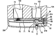
图10是示出了作为本发明的电子装置的第二实施例的医疗遥测仪中的ON状态的剖视图。10 is a cross-sectional view showing an ON state in a medical telemeter as a second embodiment of the electronic device of the present invention.
图11是示出了作为本发明的电子装置的该第二实施例的医疗遥测仪中的OFF状态的剖视图。FIG. 11 is a cross-sectional view showing an OFF state in the medical telemeter as the second embodiment of the electronic device of the present invention.
图12是从作为本发明的电子装置的该第二实施例的医疗遥测仪中的装置主体移除的盖元件的剖视图。12 is a cross-sectional view of the cover member removed from the device main body in the medical telemeter as the second embodiment of the electronic device of the present invention.
图13是示出了作为本发明的电子装置的第三实施例的医疗遥测仪的一部分的平面图。13 is a plan view showing a part of a medical telemeter as a third embodiment of the electronic device of the present invention.
图14是示出了图13的后面的平面图。FIG. 14 is a plan view showing the rear of FIG. 13 .
图15是作为本发明的电子装置的该第三实施例的医疗遥测仪的一部分的剖视图。15 is a cross-sectional view of a part of the medical telemeter as the third embodiment of the electronic device of the present invention.
具体实施方式Detailed ways
下面,将参考附图来描述本发明的电子装置的各实施例。在图中,相同的部件由相同的参考标号来表示,并将省去重复的描述。如图1所示,第一实施例的电子装置是医疗遥测仪,并且包括:具有矩形平行六面体形状的装置主体10。在该装置主体10的一个面上设置显示部11和操作按钮12,该显示部11包括LCD,并在该显示部11上显示测量状态、电池余量等,而该操作按钮12用于执行测量中所需的设定。Hereinafter, embodiments of the electronic device of the present invention will be described with reference to the accompanying drawings. In the drawings, the same components are denoted by the same reference numerals, and repeated descriptions will be omitted. As shown in FIG. 1 , the electronic device of the first embodiment is a medical telemeter, and includes a device
在装置主体10直立的状态下,分别构成连接器的插孔13A、13B设置在装置主体10的上面,使得构成另一连接器的插头14A、14B能够分别连接于该插孔13A、13B。例如,用于ECG的电极连接于该插头14A,而用于测量SpO2的传感器连接于插头14B。When the
在装置主体10直立的状态下,装置主体10的底部形成为盖元件20,并且装置主体10和盖元件20互相接合。如图2所示,弧形槽21形成在盖元件20的底面侧中,并且开关的操作部22插过该槽21,使得操作部22能够在ON位置和OFF位置之间滑动。In a state where the
在盖元件20的底面中形成月牙形凹槽23,用作为在要从装置主体10移除盖元件20的情况下指尖等抠住的手指保持部。如图3(b)所示,能够将盖元件20的外盖24从图3(a)中所示的连接位置以逆时针方向转动。由于外盖24的转动,显露出了作为内盖底板25的一部分的面。箭头M是为了指示倘若移除时的转动方向而通过切削所形成的标记。A crescent-
当拉动外盖24使其从图3(b)的状态中的装置主体10分离时,内盖底板25从装置主体10的底部拆离,并如图4所示显露出底面凹槽15。图4示出了外盖24和内盖底板25互相重叠的状态。实际上,内盖底板25从图3(b)的状态中的装置主体10分离。在装置主体10的底面凹槽15中形成收纳部16的开口,该收纳部16分别收纳用于对内部电子回路供电的电池。在该两个收纳部16之间形成收纳部17的开口,该收纳部17用于收纳设置在盖元件20中的接合片26的头部26A。在收纳部17中设置接合部(未示出),当接合片26的头部26A转动时,该接合部与头部26A接合,以使得盖元件20和装置主体10彼此接合并固定。盖元件20和装置主体10通过具有适宜长度的串接件30而彼此连接,使得当移除盖元件20时,防止盖元件20丢失。When the
图5是盖元件20的组装透视图。该盖元件20包括外盖24、旋转件31、内盖底板25、环27、内盖顶板40和接合片26。在图5中,以从下侧到上侧的方向来绘示这些部件。通过螺栓28将这些部件组装成盖元件20。FIG. 5 is an assembled perspective view of the
如图6所示,操作部22形成在旋转件31的一个面上,该操作部22是具有大致矩形平行六面体形状的小突起。旋转件31形成为圆盘状形状,并在圆盘中部具有由套管32围绕的通孔33。最外圆周部通过大台阶部34和小台阶部35与小直径圆周部接续。套管32形成为圆柱形,并且具有一部分被切掉的平面部32A。与小台阶部35接续的小直径圆周部形成螺旋地延伸的臂状片36的外廓。与大台阶部34接续的小直径圆周部延伸到臂状片36的基部36A。向外突起的突起部36B形成在臂状片36的顶端部。臂状片36具有柔韧性,其中该片关于基部36A向内和向外弯曲。As shown in FIG. 6 , an operating
接合片26下方的大直径部所插入的孔41在内盖顶板40的中部开口。在纵向上与孔41间隔大致相同距离的两个位置中分别形成各孔。由与各电池中的一个电池的负极接触的导电件构成的螺旋弹簧42经过一个孔伸出,而与另一个电池的正极接触的接触凸部43设置在另一个孔中。The
如图7所示,每个都由导电件构成的导电路径44、45连接于内盖顶板40的后面。导电路径44电连接于螺旋弹簧42。在导电路径45上设置接触凸部43,该接触凸部43形成为朝着内盖顶板40的表面一侧凸起。弹性可动片44A设置成在内盖顶板40的宽度方向上延伸,该弹性可动片44A从导电路径44的一个拐角处弯曲以相对于内盖顶板40的后面垂直直立。导电路径45具有朝着弹性可动片44A的顶端部延伸的小宽度部45A。小宽度部的顶端弯曲成相对于内盖顶板40的后面垂直直立,从而形成固定开关触点45B。弹性可动片44A的顶端部形成为与固定开关触点45B相对的可动开关触点44B。As shown in FIG. 7 ,
如图5所示,在内盖底板25上形成壁部51,该壁部51要与内盖顶板40的外周的台阶部嵌合。旋转件31的套管32所插入的孔52形成在内盖底板25的中部。在孔52的外周形成台座53,该台座53突出为一部分被切掉的环形形状。凸起壁54形成在台座53的外周的大约三分之二的部分中。As shown in FIG. 5 , a
环27放置在台座53上。该环27具有旋转件31的套管32所插入的孔55。孔55具有大致圆形形状,但是局部形成有与套管32的平面部32A对应的直线部55A。因此,在旋转件31的套管32被插入到环27的孔55中的状态下,套管32和环27如图8中所示互相一体地嵌合。在这种状态下,可以采用这样的构造,即,手指与旋转件31的操作部22接合,并且使操作部22在槽21中从ON位置滑动到OFF位置,从而使得套管32和环27一体地转动。
环27由于操作部22的滑动运动而转动。在该实施例中,操作部22在槽21的范围之内可以滑动。因此,可以将环27构造成在操作部22可滑动的范围之内可以转动。The
环27的外周具有大致圆环形状。在该环嵌合于套管32并放置在台座53上的状态下,形成有在台座53的不存在凸起壁54的边缘部的方向上突出的突起片56。环27和突起片56一体地转动。替换地,凸起壁54的两端54E可以用作为限动件,并且环27可以在台座53的不存在凸起壁54的范围之内转动。The outer circumference of the
在将旋转件31、内盖底板25和环27组装在一起的状态下,如图8所示那样装上内盖顶板40。当将操作部22定位在形成于外盖24内的槽21中的ON位置处时,环27处于在图7中通过作为虚线的点划线所表示的状态中,并且突起片56定位在导电路径44的弹性可动片44A的基部附近。因此,固定开关触点45B和相对的可动开关触点44B处于触点彼此接触的状态。当操作部22朝着槽21中的OFF位置转动时,突起片56在图7中以逆时针方向转动,以朝着导电路径44推动弹性可动片44A,并因此使固定开关触点45B和相对的可动开关触点44B彼此分离,结果得到了没有电力从电池提供到电子回路的断开状态。In a state in which the rotating
如图5所示,向内突出的轴61形成在外盖24的内底面的中部上。轴61的头部61A具有与形成在接合片26的底部中的矩形孔(未示出)相对应的矩形棱柱状形状。如图9(a)和9(b)中所示,在将轴61插入到旋转件31的通孔33中的状态下,该旋转件31设置在外盖24的内底面上。As shown in FIG. 5 , an inwardly protruding
在外盖24的内底面上,圆筒状导向壁62设置成沿着由轴61枢转地支撑的旋转件31的最外层圆周延伸。在导向壁62的内壁上,假设在纵向方向上垂直延伸的线段将外盖24二等分,那么向内突出的突起63、64分别形成在该线段与外盖24相交的两个位置处。突起63用作为相对于旋转件31的大台阶部34的限动件,而突起64用作为相对于小台阶部35的限动件。On the inner bottom surface of the
如图9(b)所示,在突起63紧靠旋转件31的大台阶部34的状态下,在臂状片36的突起部36B所定位的部分中,台阶部65形成在导向臂62的内壁上。在台阶部65中,使得高度随着在顺时针方向上前进而更高。如图9(b)所示,在突起63紧靠旋转件31的大台阶部34的状态下,臂状片36的突起部36B紧靠台阶部65,并且操作部22处于槽21中的ON位置处。此时,与旋转件31的套管嵌合的环27的突起片56位于使得固定开关触点45B与相对的可动开关触点44B彼此相接触的位置处。As shown in FIG. 9( b), in the state where the
在该状态下,当操作部22朝着槽21中的OFF位置(以图9(a)和9(b)中的顺时针方向)转动时,臂状片36弯曲,并且突起部36B前进以便越过台阶部65并且在导向壁62的内壁上滑动。当操作部进一步转动时,突起64紧靠小台阶部35而起到限动件的作用。此时,操作部22处于槽21中的OFF位置处(图9(a)),并且与旋转件31的套管嵌合的环27的突起片56位于使得固定开关触点45B与相对的可动开关触点44B彼此分离的位置处。In this state, when the
在图9(a)的状态下,与旋转件31的套管32的外壁和内盖底板25中的孔52之间的接合力(摩擦力)相比,外盖24的导向壁62的内壁和旋转件31的外周之间的接合力(摩擦力)非常小。在电池更换中要将盖元件20移除的情况下,外盖24相对于内盖底板25转动(见图3(b)),并且使得旋转件31通过上述接合力之间的差而跟随内盖底板25。In the state of FIG. 9( a), compared with the engaging force (friction force) between the outer wall of the
当获得了图9(b)的状态时,与之相对,旋转件31的套管32的外壁与内盖底板25中的孔52之间的接合力(摩擦力)没有大到使得臂状片36的突起部36B越过台阶部65,并因此旋转件31保持在图9(b)的状态中。因此,在旋转件31和外盖24之间的位置关系处于图9(b)的状态中的情况下,即使当外盖24相对于内盖底板25以任意方向转动时,旋转件31和外盖24之间的位置关系也保持在图9(b)的状态中。When the state of FIG. 9( b) is obtained, on the other hand, the engaging force (frictional force) between the outer wall of the
因此,在更换电池时移除盖元件20之前,在操作部22处于槽21中的OFF位置处(图9(a))的情况下,当外盖24相对于内盖底板25(以图9(a)和9(b)中的顺时针方向)转动时,旋转件31跟随内盖底板25而保持,臂状片36滑过导向壁62的内壁使得臂状片36的突起部36B到达台阶部65,并且突起63紧靠旋转件31的大台阶部34,从而使转动操作停止。即,在电池更换中移除盖元件20之前,即使当操作部22处于槽21的OFF位置时,操作部22也会移动到槽21中的ON位置,并且获得图9(b)的状态。Therefore, before removing the
在电池更换之后,在外盖24以使该外盖24与内盖底板25彼此重合的方向转动的情况下,臂状片36的突起部36B不越过台阶部,并且旋转件31在该旋转件保持在图9(b)的位置中的状态下与外盖24一起转动,并且外盖24与内盖底板25彼此重合。因此,操作部22定位在槽21中的ON位置处。以这种方式,电源被接通,并且电子回路开始工作。After battery replacement, when the
与之相对,在电池更换中移除盖板20之前,在操作部22处于槽21中的ON位置的情况下(图9(b)),即使当外盖24相对于内盖底板25转动时,旋转件31也会在该旋转件保持在图9(b)的位置中的状态下与外盖24一起转动。即,在更换电池中移除盖元件20之前,在操作部22处于槽21中的ON位置的情况下,在维持操作部22保持在槽21中的ON位置处的状态下,旋转件31伴随外盖24一起转动。In contrast, before the
在电池更换后,当外盖24在使该外盖24和内盖底板25彼此重合的方向上进一步转动时,旋转件31以与上述类似的方式在该旋转件保持在图9(b)的位置中的状态下与外盖24一起转动,并且外盖24和内盖底板25彼此重合。因此,电源被接通,并且电子回路开始工作。After the battery is replaced, when the
如上所述,当操作部22没有位于ON和OFF位置中预定的一个位置处时,外盖24、内盖底板25和旋转件31按照从装置主体10将盖元件20的移除,将操作部22移动到预定位置并将其保持在该位置。虽然在本实施例中的预定位置是ON位置,但是对于本领域技术人员容易想到的是,通过修改开关触点的构造,该预定位置可以改变为OFF位置。As described above, when the
图10至图12示出了第二实施例的电子装置的一部分的构造。该装置主体10A包括电子回路,并且电力从电池100提供到该电子回路。盖元件20A可接合于该装置主体10A并可从该装置主体10A拆离。该接合/拆离构造可以与第一实施例的相同,或者可替换地,可以具有由于滑动或拉/推操作的接合/拆离结构。10 to 12 show the configuration of a part of the electronic device of the second embodiment. The device
盖元件20A包括由板状导电件构成的导电路径71。螺旋弹簧73由导电件构成,并且突起71A设置在导电路径71上。杯状压片74设置在突起71的正下方。压片74通过从盖元件20A的侧壁部延伸的中间顶板75的顶端部支撑在孔76的位置处。具有上限动件和下限动件的压销77接合于盖元件20A的底面中在压片74下方的孔。弹簧78插入在压销77的上限动件和盖元件20A的底面之间,以朝着压片74推动压销77。The
L状杆件81设置在压销77的上限动件的那侧中。在杆件81中,基部81A插入到与盖元件20A的顶板贯通的通孔82中,并且从基部81A垂直弯曲的臂部81B是易弯曲的。杆件81由在通孔82下方伸出的支撑部83来支撑,并且能够被提升到在臂部81B上方延伸的限动件84的位置。臂部81B的顶端部与压销77的上限动件相接触。当人工操作该压销77时,由于臂部81B的柔韧性,可以通过压销77的上限动件使该顶端部向上或向下移动,但是并不使其由于弹簧78的力而弯曲。在通孔82的上部中形成斜面89,该斜面89在远离限动件84的一侧包括宽度增加的大宽度部88,并且该斜面随着向下延长而变窄。An L-shaped
导电路径71的突起71A与一个电池的正极相接触或不相接触、设置在供电线路中、并且用作使供电线路关闭/打开的开关触点。导电路径71保持为在盖元件20A中可以垂直移动。压销77包括操作部,该操作部在ON位置和OFF位置之间移动,以便使开关触点移动,从而关闭/打开供电线路。该ON位置是压销77被推入到盖元件20A中的位置(图10),而该OFF位置是压销77被从盖元件20A拉出的位置(图11)。The
在上述构造中,在安装了电池100并且盖元件20A与装置主体10A彼此接合的状态下,当压销77被人工推入到盖元件20A中时,压销77的上限动件在越过臂部81B的同时移动到上部,压片74被弹簧78的推进力推压,并且在该片上方存在的突起71A被向上推动到与电池100中的一个电池的正极相接触,从而达到ON状态(图10)。In the above configuration, in a state where the
在ON状态下,当压销77被人工从盖元件20A拉出时,压销77的上限动件使得臂部81B弯曲,并且在越过该臂部的同时进一步移动到下部,并且获得压片74的上限动件被臂部81B的顶端部推动的状态In the ON state, when the
(图11)。压片74不受到弹簧78的推进,并且突起71A向下移动,因此获得该突起不与电池100的正极相接触的OFF状态。(Figure 11). The
当在图10所示的ON状态下为了进行电池更换而移除盖元件20A时,维持该状态,并且保持ON状态。在电池更换之后,当关闭盖元件20A时,保持图10所示的ON状态。When the
当在图11所示的OFF状态下为了进行电池更换而移除盖元件20A时,压销77受到弹簧78的推进,并且向上移动。此时,压销77的上限动件在臂部81B位于该限动件上的状态下移动。因此,杆件81的基部81A的一部分从通孔82伸出,但是被限动件84阻挡以免进一步上升(图12),并且杆件81被朝着大宽度部88推出、沿着斜面89滑下、并然后被支撑部支撑。杆件81返回到图10中的所示的位置。在该状态下,压销77的上限动件利用弹簧78的推进力向上推压压片74,并且存在于该限动件上方的突起71A被推动直到位于该突起能够与电池100的正极相接触的ON位置的位置。When the
如上所示,当用作为操作部的压销77没有处于ON位置和OFF位置中的预定的一个位置时,压销77、弹簧78、杆件81和通孔82按照将盖元件20A从装置主体10A的移除,将压销77移动到该预定位置并将其保持。而且在第二实施例中,在电池更换中移除盖元件20A之前,即使当压销77处于OFF位置时,压销77也能移动到ON位置。As shown above, when the
图13至15示出了第三实施例的电子装置的一部分的构造。在图13所示的盖元件20B的内顶盖90中形成滑动槽91,滑动壁沿着该滑动槽滑动。该滑动壁形成在与第一实施例相似的电子装置10B的底部上。盖元件20B能够滑动而被移除。螺旋弹簧92A和突起93A从盖元件20B的内顶盖90突出。13 to 15 show the configuration of a part of the electronic device of the third embodiment. In the inner
在图13所示的盖元件20B的内顶盖90的后面上设置导电路径92和导电路径93,该导电路径92连接于螺旋弹簧92A并由导电件构成,该导电路径93中形成有突起93A并由导电件构成。On the rear surface of the inner
在盖元件20B的内顶盖90中,细长的滑动孔94在图13中所示的中部的稍偏右侧的部分中开口。滑动轨94A分别形成在滑动孔94的各长侧中。具有矩形平行六面体形状的操作部95嵌合在滑动孔94中。滑动轨94A的靠近导电路径92的端部构成ON位置,而该滑动轨94A的在纵向上与ON位置相对的端部构成OFF位置。连接于导电路径93的基部93B的并且易弯的易弯片93C在ON位置附近延伸。易弯片的顶端部相对于导电路径93的平面垂直弯曲以形成为开关可动触点93D。在开关可动触点93D附近形成开关固定触点92B,该开关固定触点与开关可动触点93D相对并且相对于导电路径92的平面垂直地弯曲。In the inner
在操作部95的侧壁中,滑动槽95A分别形成在与滑动孔94中的滑动轨94A对应的位置处,使得操作部95能够在ON位置和OFF位置之间滑动。当操作部95定位在ON位置时,该操作部抵着相对的开关固定触点92B推压开关可动触点93D,并且获得电源ON状态。In the side walls of the
如图15所示,当侧向观看滑动孔94时,每个滑动轨94A在相对于中部稍靠近于ON位置的部分中都具有台阶部94B,使得操作部95在靠近于ON位置的部分处下沉,并且在靠近于OFF位置的一侧上突出。As shown in FIG. 15 , when the
如图15所示,在装置主体10的底面中,台阶部96形成在与滑动孔94在OFF位置一侧上的端部对应的位置处,并且相对于台阶部96位于外侧的部分形成为朝着盖元件20B突出的凸部96A。在装置主体10B的底面中,相对于台阶部96位于中间侧的部分构造为与盖元件20B形成间隙的凹部96B。凸部96A和凹部96B之间的尺寸相当于台阶部94B在滑动轨94A中的阶差。As shown in FIG. 15 , in the bottom surface of the device
在移除盖元件20B的情况下,当盖元件20B在图15中的箭头S的方向上滑动时,形成在装置主体10B的底部上的滑动壁在盖元件20B中形成的滑动槽91内滑动,以便能够利用滑动操作来移除盖元件20B。此时,当操作部95位于OFF位置时,装置主体10B的台阶部96推压操作部95的头部以使该部分朝着ON位置移动,并且操作部95在滑动轨94A中越过台阶部94B而到达ON位置。在该状态下,操作部95下沉,并且装置主体10B的台阶部96不推压操作部95的头部。With the cover member 20B removed, when the cover member 20B slides in the direction of arrow S in FIG. , so that the cover member 20B can be removed with a sliding operation. At this time, when the
如上所述,当操作部95没有位于ON和OFF位置中的预定的一个位置处时,滑动孔94、滑动轨94A和台阶部94B按照从装置主体10B移除盖元件20B,使操作部95移动到预定位置处并将其保持。而且在第三实施例中,在电池更换中移除盖元件20B之前,即使当操作部95位于滑动孔94中的OFF位置时,操作部95也能移动到ON位置。在电池更换后,当盖元件20B在与图15中的箭头S相反的方向上滑动时,操作部95没有任何影响地定位在ON位置处,并且抵着相对的开关固定触点92B来推压开关可动触点93D,从而获得电源ON状态。As described above, when the
根据本发明的一方面,当移除盖元件时,操作部被移动到预定位置并且保持在该预定位置处,使得在电池更换后接通或断开电源。因此,无须麻烦的操作,并且,即使当操作者忘记进行接通或断开电源的操作时,电源也能被设定到预定状态。因此,提升了工作效率。此外,在预定状态是ON状态的情况下,可以避免由于在电池更换后操作者忘记接通或断开电子装置的电源的人为错误而使得测量不能进行的状况。According to an aspect of the present invention, when the cover member is removed, the operation portion is moved to and held at a predetermined position so that power is turned on or off after battery replacement. Therefore, troublesome operations are unnecessary, and even when the operator forgets to perform the operation of turning on or off the power supply, the power supply can be set to a predetermined state. Therefore, work efficiency is improved. Furthermore, in the case where the predetermined state is the ON state, it is possible to avoid a situation where measurement cannot be performed due to a human error in which the operator forgets to turn on or off the power of the electronic device after battery replacement.
根据本发明的一方面,因此,即使在盖元件接合于装置主体的情况下,当移除盖元件时,也保持操作部被移动到预定位置的状态,并因此在电池更换后确保电源接通或断开。According to an aspect of the present invention, therefore, even in the case where the cover member is engaged with the device main body, when the cover member is removed, the state in which the operation portion is moved to a predetermined position is maintained, and thus the power-on is ensured after battery replacement or disconnect.
根据本发明的一方面,在通过转动或滑动操作移除盖元件的情况下,保持操作部被移动到预定位置的状态,并因此在电池更换之后确保电源接通或断开。According to an aspect of the present invention, in a case where the cover member is removed by a turning or sliding operation, a state in which the operation portion is moved to a predetermined position is maintained, and thus power ON or OFF is ensured after battery replacement.
Claims (10)
Applications Claiming Priority (2)
| Application Number | Priority Date | Filing Date | Title |
|---|---|---|---|
| JP2009-212442 | 2009-09-14 | ||
| JP2009212442A JP5083674B2 (en) | 2009-09-14 | 2009-09-14 | Electronic equipment |
Publications (2)
| Publication Number | Publication Date |
|---|---|
| CN102024924A true CN102024924A (en) | 2011-04-20 |
| CN102024924B CN102024924B (en) | 2014-08-13 |
Family
ID=43385671
Family Applications (1)
| Application Number | Title | Priority Date | Filing Date |
|---|---|---|---|
| CN201010283577.XA Expired - Fee Related CN102024924B (en) | 2009-09-14 | 2010-09-13 | Electronic apparatus |
Country Status (4)
| Country | Link |
|---|---|
| US (1) | US8399785B2 (en) |
| EP (1) | EP2315295B1 (en) |
| JP (1) | JP5083674B2 (en) |
| CN (1) | CN102024924B (en) |
Families Citing this family (4)
| Publication number | Priority date | Publication date | Assignee | Title |
|---|---|---|---|---|
| US8754343B2 (en) * | 2009-09-30 | 2014-06-17 | Apple Inc. | Rotary slide switches |
| JP5522752B2 (en) * | 2012-06-19 | 2014-06-18 | Necインフロンティア株式会社 | Information terminal device and battery lid fixing method of information terminal device |
| JP7572854B2 (en) * | 2020-12-28 | 2024-10-24 | フクダ電子株式会社 | Medical Devices |
| CN117039321A (en) * | 2023-09-06 | 2023-11-10 | 西安华科光电有限公司 | Battery cover assembly and split type fusion sighting device |
Citations (6)
| Publication number | Priority date | Publication date | Assignee | Title |
|---|---|---|---|---|
| US3071747A (en) * | 1958-10-15 | 1963-01-01 | Welch Allyn Inc | Battery handle construction |
| US3863062A (en) * | 1972-01-26 | 1975-01-28 | Joseph Adalbert Caron | Key holder with flashlight |
| US5097384A (en) * | 1988-10-18 | 1992-03-17 | Sharp Kabushiki Kaisha | Battery powered apparatus having data storage circuits and power off switch automatically actuated by opening of replaceable battery compartment door |
| JPH05225140A (en) * | 1992-02-10 | 1993-09-03 | Sharp Corp | Battery mounting device |
| JP2007000445A (en) * | 2005-06-24 | 2007-01-11 | Ngk Spark Plug Co Ltd | Respiratory state monitoring device and respiratory state monitoring system |
| CN101291153A (en) * | 2007-04-16 | 2008-10-22 | 明基电通股份有限公司 | portable electronic device |
Family Cites Families (12)
| Publication number | Priority date | Publication date | Assignee | Title |
|---|---|---|---|---|
| JPS6031438B2 (en) | 1979-10-13 | 1985-07-22 | ソニー株式会社 | hearing aid battery case |
| NL8004115A (en) * | 1980-07-17 | 1982-02-16 | Philips Nv | ELECTRICAL APPLIANCE, FOR example A SHAVING DEVICE, EQUIPPED WITH A COUNTING MACHINE. |
| US4636596A (en) * | 1985-09-11 | 1987-01-13 | Nikko Co., Ltd. | Power switch for a battery |
| JPH0330636U (en) * | 1989-08-02 | 1991-03-26 | ||
| US5038017A (en) * | 1990-02-13 | 1991-08-06 | Stephen Slenker | Battery pack |
| DE9015923U1 (en) * | 1990-11-22 | 1992-03-19 | Otto Bock Orthopädische Industrie Besitz- und Verwaltungs-Kommanditgesellschaft, 3408 Duderstadt | accumulator |
| JP3003509U (en) * | 1994-04-26 | 1994-10-25 | 旭光学工業株式会社 | Battery storage mechanism |
| JP3030636U (en) | 1996-04-26 | 1996-11-01 | フクダ電子株式会社 | Battery cover with built-in switch |
| JP2000223093A (en) * | 1999-01-29 | 2000-08-11 | Matsushita Electric Works Ltd | Battery-powered electrical equipment |
| JP2000251946A (en) * | 1999-02-26 | 2000-09-14 | Mitsumi Electric Co Ltd | Reset switch mechanism |
| DE20209255U1 (en) * | 2002-06-14 | 2002-11-28 | Shiau, Wen-Chin, Kuei-Shan, Taoyuan | Flashlight with end cap switch |
| JP5360968B2 (en) | 2008-03-03 | 2013-12-04 | パナソニック株式会社 | Information processing apparatus and integrated circuit |
-
2009
- 2009-09-14 JP JP2009212442A patent/JP5083674B2/en not_active Expired - Fee Related
-
2010
- 2010-09-13 CN CN201010283577.XA patent/CN102024924B/en not_active Expired - Fee Related
- 2010-09-13 US US12/880,243 patent/US8399785B2/en not_active Expired - Fee Related
- 2010-09-14 EP EP10176581.6A patent/EP2315295B1/en not_active Not-in-force
Patent Citations (6)
| Publication number | Priority date | Publication date | Assignee | Title |
|---|---|---|---|---|
| US3071747A (en) * | 1958-10-15 | 1963-01-01 | Welch Allyn Inc | Battery handle construction |
| US3863062A (en) * | 1972-01-26 | 1975-01-28 | Joseph Adalbert Caron | Key holder with flashlight |
| US5097384A (en) * | 1988-10-18 | 1992-03-17 | Sharp Kabushiki Kaisha | Battery powered apparatus having data storage circuits and power off switch automatically actuated by opening of replaceable battery compartment door |
| JPH05225140A (en) * | 1992-02-10 | 1993-09-03 | Sharp Corp | Battery mounting device |
| JP2007000445A (en) * | 2005-06-24 | 2007-01-11 | Ngk Spark Plug Co Ltd | Respiratory state monitoring device and respiratory state monitoring system |
| CN101291153A (en) * | 2007-04-16 | 2008-10-22 | 明基电通股份有限公司 | portable electronic device |
Also Published As
| Publication number | Publication date |
|---|---|
| US20110214971A1 (en) | 2011-09-08 |
| CN102024924B (en) | 2014-08-13 |
| JP2011060734A (en) | 2011-03-24 |
| JP5083674B2 (en) | 2012-11-28 |
| EP2315295B1 (en) | 2018-10-24 |
| EP2315295A1 (en) | 2011-04-27 |
| US8399785B2 (en) | 2013-03-19 |
Similar Documents
| Publication | Publication Date | Title |
|---|---|---|
| JP3130882U (en) | Card device | |
| CN102024924B (en) | Electronic apparatus | |
| CN113131556A (en) | Charging device for physiological signal sensor | |
| CN102090136B (en) | Radio base station apparatus | |
| JP2009054381A (en) | Flexible board connection device | |
| CN103733291A (en) | Connector and connector bar | |
| JP2011034950A (en) | Battery holder and portable electronic device using the same | |
| JP3120077U (en) | IC socket | |
| US8877130B2 (en) | Device for measuring biological sample | |
| JP5888507B2 (en) | Outlet | |
| JP5046794B2 (en) | Medical electronics | |
| CN108336794A (en) | A kind of charging unit and handheld game machine for mobile terminal | |
| JP3030636U (en) | Battery cover with built-in switch | |
| CN222508861U (en) | Flashlight charging box and lighting assembly | |
| JP2005011715A (en) | Battery holder | |
| WO2017057704A1 (en) | Pill management device | |
| JPH0447992Y2 (en) | ||
| CN216090844U (en) | Allergy identification card slot | |
| JP3912597B2 (en) | Charger | |
| CN215383013U (en) | Cup set | |
| JP2016031781A (en) | Card connection structure for electronic equipment | |
| CN219553777U (en) | Electronic device and insulin pen | |
| TWM465689U (en) | Communication connector and electronic device using the same | |
| JPH1097876A (en) | Charging device | |
| JP2003086285A (en) | Power supply plug |
Legal Events
| Date | Code | Title | Description |
|---|---|---|---|
| C06 | Publication | ||
| PB01 | Publication | ||
| C10 | Entry into substantive examination | ||
| SE01 | Entry into force of request for substantive examination | ||
| C14 | Grant of patent or utility model | ||
| GR01 | Patent grant | ||
| CF01 | Termination of patent right due to non-payment of annual fee |
Granted publication date: 20140813 Termination date: 20210913 |
|
| CF01 | Termination of patent right due to non-payment of annual fee |