CN101978618B - Multi-resolution beamforming in mimo systems - Google Patents
Multi-resolution beamforming in mimo systems Download PDFInfo
- Publication number
- CN101978618B CN101978618B CN2009801092934A CN200980109293A CN101978618B CN 101978618 B CN101978618 B CN 101978618B CN 2009801092934 A CN2009801092934 A CN 2009801092934A CN 200980109293 A CN200980109293 A CN 200980109293A CN 101978618 B CN101978618 B CN 101978618B
- Authority
- CN
- China
- Prior art keywords
- preferred
- equipment
- wave beam
- sector
- transmit direction
- Prior art date
- Legal status (The legal status is an assumption and is not a legal conclusion. Google has not performed a legal analysis and makes no representation as to the accuracy of the status listed.)
- Active
Links
Images


Classifications
-
- H—ELECTRICITY
- H04—ELECTRIC COMMUNICATION TECHNIQUE
- H04B—TRANSMISSION
- H04B7/00—Radio transmission systems, i.e. using radiation field
- H04B7/02—Diversity systems; Multi-antenna system, i.e. transmission or reception using multiple antennas
- H04B7/04—Diversity systems; Multi-antenna system, i.e. transmission or reception using multiple antennas using two or more spaced independent antennas
- H04B7/0413—MIMO systems
- H04B7/0417—Feedback systems
-
- H—ELECTRICITY
- H04—ELECTRIC COMMUNICATION TECHNIQUE
- H04B—TRANSMISSION
- H04B7/00—Radio transmission systems, i.e. using radiation field
- H04B7/02—Diversity systems; Multi-antenna system, i.e. transmission or reception using multiple antennas
- H04B7/04—Diversity systems; Multi-antenna system, i.e. transmission or reception using multiple antennas using two or more spaced independent antennas
- H04B7/0413—MIMO systems
- H04B7/0426—Power distribution
- H04B7/043—Power distribution using best eigenmode, e.g. beam forming or beam steering
-
- H—ELECTRICITY
- H04—ELECTRIC COMMUNICATION TECHNIQUE
- H04B—TRANSMISSION
- H04B7/00—Radio transmission systems, i.e. using radiation field
- H04B7/02—Diversity systems; Multi-antenna system, i.e. transmission or reception using multiple antennas
- H04B7/04—Diversity systems; Multi-antenna system, i.e. transmission or reception using multiple antennas using two or more spaced independent antennas
- H04B7/0491—Diversity systems; Multi-antenna system, i.e. transmission or reception using multiple antennas using two or more spaced independent antennas using two or more sectors, i.e. sector diversity
-
- H—ELECTRICITY
- H04—ELECTRIC COMMUNICATION TECHNIQUE
- H04B—TRANSMISSION
- H04B7/00—Radio transmission systems, i.e. using radiation field
- H04B7/02—Diversity systems; Multi-antenna system, i.e. transmission or reception using multiple antennas
- H04B7/04—Diversity systems; Multi-antenna system, i.e. transmission or reception using multiple antennas using two or more spaced independent antennas
- H04B7/06—Diversity systems; Multi-antenna system, i.e. transmission or reception using multiple antennas using two or more spaced independent antennas at the transmitting station
- H04B7/0613—Diversity systems; Multi-antenna system, i.e. transmission or reception using multiple antennas using two or more spaced independent antennas at the transmitting station using simultaneous transmission
- H04B7/0615—Diversity systems; Multi-antenna system, i.e. transmission or reception using multiple antennas using two or more spaced independent antennas at the transmitting station using simultaneous transmission of weighted versions of same signal
- H04B7/0619—Diversity systems; Multi-antenna system, i.e. transmission or reception using multiple antennas using two or more spaced independent antennas at the transmitting station using simultaneous transmission of weighted versions of same signal using feedback from receiving side
- H04B7/0621—Feedback content
- H04B7/0626—Channel coefficients, e.g. channel state information [CSI]
-
- H—ELECTRICITY
- H04—ELECTRIC COMMUNICATION TECHNIQUE
- H04B—TRANSMISSION
- H04B7/00—Radio transmission systems, i.e. using radiation field
- H04B7/02—Diversity systems; Multi-antenna system, i.e. transmission or reception using multiple antennas
- H04B7/04—Diversity systems; Multi-antenna system, i.e. transmission or reception using multiple antennas using two or more spaced independent antennas
- H04B7/06—Diversity systems; Multi-antenna system, i.e. transmission or reception using multiple antennas using two or more spaced independent antennas at the transmitting station
- H04B7/0613—Diversity systems; Multi-antenna system, i.e. transmission or reception using multiple antennas using two or more spaced independent antennas at the transmitting station using simultaneous transmission
- H04B7/0615—Diversity systems; Multi-antenna system, i.e. transmission or reception using multiple antennas using two or more spaced independent antennas at the transmitting station using simultaneous transmission of weighted versions of same signal
- H04B7/0619—Diversity systems; Multi-antenna system, i.e. transmission or reception using multiple antennas using two or more spaced independent antennas at the transmitting station using simultaneous transmission of weighted versions of same signal using feedback from receiving side
- H04B7/0621—Feedback content
- H04B7/0634—Antenna weights or vector/matrix coefficients
-
- H—ELECTRICITY
- H04—ELECTRIC COMMUNICATION TECHNIQUE
- H04B—TRANSMISSION
- H04B7/00—Radio transmission systems, i.e. using radiation field
- H04B7/02—Diversity systems; Multi-antenna system, i.e. transmission or reception using multiple antennas
- H04B7/04—Diversity systems; Multi-antenna system, i.e. transmission or reception using multiple antennas using two or more spaced independent antennas
- H04B7/06—Diversity systems; Multi-antenna system, i.e. transmission or reception using multiple antennas using two or more spaced independent antennas at the transmitting station
- H04B7/0613—Diversity systems; Multi-antenna system, i.e. transmission or reception using multiple antennas using two or more spaced independent antennas at the transmitting station using simultaneous transmission
- H04B7/0684—Diversity systems; Multi-antenna system, i.e. transmission or reception using multiple antennas using two or more spaced independent antennas at the transmitting station using simultaneous transmission using different training sequences per antenna
-
- H—ELECTRICITY
- H04—ELECTRIC COMMUNICATION TECHNIQUE
- H04B—TRANSMISSION
- H04B7/00—Radio transmission systems, i.e. using radiation field
- H04B7/02—Diversity systems; Multi-antenna system, i.e. transmission or reception using multiple antennas
- H04B7/04—Diversity systems; Multi-antenna system, i.e. transmission or reception using multiple antennas using two or more spaced independent antennas
- H04B7/08—Diversity systems; Multi-antenna system, i.e. transmission or reception using multiple antennas using two or more spaced independent antennas at the receiving station
- H04B7/0837—Diversity systems; Multi-antenna system, i.e. transmission or reception using multiple antennas using two or more spaced independent antennas at the receiving station using pre-detection combining
- H04B7/0842—Weighted combining
- H04B7/0848—Joint weighting
- H04B7/0851—Joint weighting using training sequences or error signal
-
- H—ELECTRICITY
- H04—ELECTRIC COMMUNICATION TECHNIQUE
- H04B—TRANSMISSION
- H04B7/00—Radio transmission systems, i.e. using radiation field
- H04B7/02—Diversity systems; Multi-antenna system, i.e. transmission or reception using multiple antennas
- H04B7/04—Diversity systems; Multi-antenna system, i.e. transmission or reception using multiple antennas using two or more spaced independent antennas
- H04B7/08—Diversity systems; Multi-antenna system, i.e. transmission or reception using multiple antennas using two or more spaced independent antennas at the receiving station
- H04B7/0837—Diversity systems; Multi-antenna system, i.e. transmission or reception using multiple antennas using two or more spaced independent antennas at the receiving station using pre-detection combining
- H04B7/0842—Weighted combining
- H04B7/086—Weighted combining using weights depending on external parameters, e.g. direction of arrival [DOA], predetermined weights or beamforming
-
- H—ELECTRICITY
- H04—ELECTRIC COMMUNICATION TECHNIQUE
- H04B—TRANSMISSION
- H04B7/00—Radio transmission systems, i.e. using radiation field
- H04B7/02—Diversity systems; Multi-antenna system, i.e. transmission or reception using multiple antennas
- H04B7/04—Diversity systems; Multi-antenna system, i.e. transmission or reception using multiple antennas using two or more spaced independent antennas
- H04B7/06—Diversity systems; Multi-antenna system, i.e. transmission or reception using multiple antennas using two or more spaced independent antennas at the transmitting station
- H04B7/0613—Diversity systems; Multi-antenna system, i.e. transmission or reception using multiple antennas using two or more spaced independent antennas at the transmitting station using simultaneous transmission
- H04B7/0615—Diversity systems; Multi-antenna system, i.e. transmission or reception using multiple antennas using two or more spaced independent antennas at the transmitting station using simultaneous transmission of weighted versions of same signal
- H04B7/0617—Diversity systems; Multi-antenna system, i.e. transmission or reception using multiple antennas using two or more spaced independent antennas at the transmitting station using simultaneous transmission of weighted versions of same signal for beam forming
-
- H—ELECTRICITY
- H04—ELECTRIC COMMUNICATION TECHNIQUE
- H04B—TRANSMISSION
- H04B7/00—Radio transmission systems, i.e. using radiation field
- H04B7/02—Diversity systems; Multi-antenna system, i.e. transmission or reception using multiple antennas
- H04B7/04—Diversity systems; Multi-antenna system, i.e. transmission or reception using multiple antennas using two or more spaced independent antennas
- H04B7/06—Diversity systems; Multi-antenna system, i.e. transmission or reception using multiple antennas using two or more spaced independent antennas at the transmitting station
- H04B7/0613—Diversity systems; Multi-antenna system, i.e. transmission or reception using multiple antennas using two or more spaced independent antennas at the transmitting station using simultaneous transmission
- H04B7/0615—Diversity systems; Multi-antenna system, i.e. transmission or reception using multiple antennas using two or more spaced independent antennas at the transmitting station using simultaneous transmission of weighted versions of same signal
- H04B7/0619—Diversity systems; Multi-antenna system, i.e. transmission or reception using multiple antennas using two or more spaced independent antennas at the transmitting station using simultaneous transmission of weighted versions of same signal using feedback from receiving side
- H04B7/0621—Feedback content
- H04B7/0628—Diversity capabilities
Abstract
Certain aspects of the present disclosure relate to methods for beamforming that achieve beamforming optimality criterions. Some proposed beamforming techniques are based on antenna directions with multiple resolutions. The methods comprise: receiving training signals transmitted from a device using a first set of transmit directions; deriving, from the first set of transmit directions, a preferred transmit direction; and providing, as feedback to the device, an indication of the preferred transmit direction to the device, wherein the feedback is provided by sweeping through a second set of transmit directions.
Description
Require priority based on 35U.S.C. § 119
That the application requires to enjoy is that on March 17th, 2008 submits to, attorney is that 082841P1, application number are 61/037, the priority of 139 U.S. Provisional Patent Application, this temporary patent application has transferred the application's assignee, therefore be incorporated to the application with way of reference clearly.
Technical field
Put it briefly, some aspect of the present invention relates to radio communication, and specifically, the wave beam that some aspect of the present invention relates to signal transmission forms.
Background technology
Support double mode ultra broadband (UWB) physical layer (PHY) of single carrier and OFDM (OFDM) modulation can use common mode.UWB PHY can for example, communicate by letter for millimeter wave (, carrier frequency is 60GHz).Common mode is the single carrier mode that single carrier equipment and OFDM equipment are used for beacon, network control signaling and base speed data signal post.Generally, common mode is that to carry out interactive operation between different equipment and different network necessary.
For space diversity and array gain are provided, millimetre-wave attenuator can also be used wave beam to form on one or more antennas.Numerous antenna configurations such as single antenna unit, sectorized antennas (sectored antenna), change type antenna (switched antenna) and one dimension (1-D) and two dimension (2-D) aerial array can support wave beam to form.Conventional wave beam such as eigen beam forms (Eigen-beamforming) forms and needs channel state information matrix or beam forming matrix, to feed back to emission array.Institute of Electrical and Electric Engineers (IEEE) 802.11n standard specifies comprise the feedback information of the following: the row and column size of feedback matrix, subcarrier grouping big or small (for example, bunch size), quantization bit size and start to the array of the actual quantization data cell of high sub-carrier indices from minimum sub-carrier indices.In order to use pre-coding matrix to carry out wave beam formation, the index that is precoding matrix codebook by the content replacement by beam forming matrix reduces feedback information.
The wave beam of considering two types forms agreement: wave beam forms (on-demandbeamforming) and active beam formation (pro-active beamforming) as required.As required wave beam form can be used between two equipment (DEV) or be used in piconet (piconet) controller (PNC) and equipment (DEV) between, wave beam forms and can occur period in the channel time allocation (CTA) of distributing to DEV in order to carry out wave beam formation as required.When PNC is the data source of one or more DEV, can use active beam to form.This agreement makes a plurality of DEV can train their receiver antenna, in order to preferably receive from PNC in low expense situation.
Consider that two kinds of wave beams form Optimality Criteria: the switched-beam (guiding that is applicable to all antenna configurations, steering) and follow the tracks of (BST) criterion, and for the directional diagram (Pattern) of 1-D linear antenna arrays and 2-D planar antenna array estimate and follow the tracks of (PET) option.Support all DEV of PET method can support the BST criterion.All support the PET criterion if form two DEV of communication link, can only use the PET criterion.Select preferred wave beam one group of wave beam of BST based on from given, PET is based on finding Beam-former and combiner vector (that is, antenna weight), and wherein, these vectors are not to fall into one group of given beam direction.
Therefore, need in the art to realize efficiently that wave beam forms the method for Optimality Criteria.
Summary of the invention
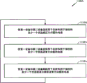
Some aspect provides a kind of method for radio communication.Put it briefly, the method comprises: receive the training signal that uses the first transmit direction collection emission from an equipment; Derive the preferred emission direction from described the first transmit direction collection; The indication of preferred emission direction is provided to described equipment, usings as the feedback to described equipment, wherein said feedback provides by scanning the second transmit direction collection.
Some aspect provides a kind of device for radio communication.Put it briefly, this device comprises: receiver, for receiving the training signal that uses the first transmit direction collection emission from an equipment; Derived circuit, for deriving the preferred emission direction from described the first transmit direction collection; Circuit is provided, the indication of preferred emission direction is provided to described equipment, using as the feedback to described equipment, wherein said feedback provides by scanning the second transmit direction collection.
Some aspect provides a kind of device for radio communication.Put it briefly, this device comprises: receiver module, for receiving the training signal that uses the first transmit direction collection emission from an equipment; Derive module, for from described the first transmit direction collection, deriving the preferred emission direction; Module is provided, for the indication of preferred emission direction is provided to described equipment, usings as the feedback to described equipment, wherein said feedback provides by scanning the second transmit direction collection.
Some aspect provides a kind of computer program for radio communication.Described computer program comprises computer-readable medium, and its coding is useful on the executable instruction of carrying out following operation: receive the training signal that uses the first transmit direction collection emission from an equipment; Derive the preferred emission direction from described the first transmit direction collection; The indication of preferred emission direction is provided to described equipment, usings as the feedback to described equipment, wherein said feedback provides by scanning the second transmit direction collection.
Some aspect provides a kind of access point.Put it briefly, described access point comprises: at least one pair of antenna; Receiver, for using the training signal of the first transmit direction collection emission from an equipment via described at least one pair of antenna reception; Derived circuit, for deriving the preferred emission direction from described the first transmit direction collection; Circuit is provided, for the indication of preferred emission direction is provided to described equipment, usings as the feedback to described equipment, wherein said feedback provides by scanning the second transmit direction collection.
Some aspect provides a kind of method for radio communication.Put it briefly, the method comprises: use the first transmit direction collection to an equipment transmitting training signal; Receive the indication of at least one the first preferred emission direction derived from described the first transmit direction collection from described equipment; Use the second transmit direction collection to described equipment transmitting training signal, wherein said the second transmit direction collection is derived from described at least one first preferred emission direction; Receive the indication of at least one the second preferred emission direction derived from described the second transmit direction collection from described equipment; Use described at least one second preferred emission direction and described equipment to communicate.
Some aspect provides a kind of device for radio communication.Put it briefly, this device comprises: use the circuit of the first transmit direction collection to an equipment transmitting training signal; Receive the circuit of the indication of at least one the first preferred emission direction derived from described the first transmit direction collection from described equipment; Use the circuit of the second transmit direction collection to described equipment transmitting training signal, wherein said the second transmit direction collection is derived from described at least one first preferred emission direction; Receive the circuit of the indication of at least one the second preferred emission direction derived from described the second transmit direction collection from described equipment; The circuit that uses described at least one second preferred emission direction and described equipment to communicate.
Some aspect provides a kind of device for radio communication.Put it briefly, this device comprises: use the module of the first transmit direction collection to an equipment transmitting training signal; Receive the module of the indication of at least one the first preferred emission direction derived from described the first transmit direction collection from described equipment; Use the module of the second transmit direction collection to described equipment transmitting training signal, wherein said the second transmit direction collection is derived from described at least one first preferred emission direction; Receive the module of the indication of at least one the second preferred emission direction derived from described the second transmit direction collection from described equipment; The module of using described at least one second preferred emission direction and described equipment to communicate.
Some aspect provides a kind of computer program for radio communication.Described computer program comprises computer-readable medium, and its coding is useful on the executable instruction of carrying out following operation: use the first transmit direction collection to an equipment transmitting training signal; Receive the indication of at least one the first preferred emission direction derived from described the first transmit direction collection from described equipment; Use the second transmit direction collection to described equipment transmitting training signal, wherein said the second transmit direction collection is derived from described at least one first preferred emission direction; Receive the indication of at least one the second preferred emission direction derived from described the second transmit direction collection from described equipment; Use described at least one second preferred emission direction and described equipment to communicate.
Some aspect provides a kind of access point.Put it briefly, described access point comprises: at least one pair of antenna; Use the circuit of the first transmit direction collection via an equipment transmitting training signal of described at least one pair of sky alignment; Receive the circuit of the indication of at least one the first preferred emission direction derived from described the first transmit direction collection from described equipment via described at least one pair of antenna; Use the circuit of the second transmit direction collection via the described at least one pair of described equipment transmitting training of sky alignment signal, wherein said the second transmit direction collection is derived from described at least one first preferred emission direction; Receive the circuit of the indication of at least one the second preferred emission direction derived from described the second transmit direction collection from described equipment via described at least one pair of antenna; The circuit that uses described at least one second preferred emission direction and described equipment to communicate.
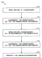
Some aspect provides a kind of method for radio communication.Put it briefly, the method comprises: receive the training signal that uses one group of sector transmission from an equipment; Derive at least one preferred sector from described one group of sector; The indication of described at least one preferred sector is provided to described equipment, usings as the feedback to described equipment, wherein said feedback is to provide by the scanning transmit direction collection relevant to sector; The training signal of at least one group of beam transmission is used in reception from described equipment, wherein said at least one group of wave beam derived from described at least one preferred sector; Derive at least one preferred wave beam from described at least one group of wave beam; The indication of described at least one preferred wave beam is provided to described equipment, usings as the feedback to described equipment, wherein said feedback is by being used described at least one preferred sector to provide; Wherein, sector is the antenna pattern that covers the certain space zone, with the area of space that sector covers, compares, and wave beam is the antenna pattern that covers less area of space.
Some aspect provides a kind of device for radio communication.Put it briefly, this device comprises: receive the circuit that uses the training signal of one group of sector transmission from an equipment; Derive the circuit of at least one preferred sector from described one group of sector; The circuit of the indication of described at least one preferred sector is provided to described equipment, usings as the feedback to described equipment, wherein said feedback is to provide by the scanning transmit direction collection relevant to sector; The circuit of the training signal of at least one group of beam transmission is used in reception from described equipment, wherein said at least one group of wave beam derived from described at least one preferred sector; Derive the circuit of at least one preferred wave beam from described at least one group of wave beam; The circuit of the indication of described at least one preferred wave beam is provided to described equipment, usings as the feedback to described equipment, wherein said feedback is by being used described at least one preferred sector to provide; Wherein, sector is the antenna pattern that covers the certain space zone, with the area of space that sector covers, compares, and wave beam is the antenna pattern that covers less area of space.
Some aspect provides a kind of device for radio communication.Put it briefly, this device comprises: receive the module of using the training signal of one group of sector transmission from an equipment; Derive the module of at least one preferred sector from described one group of sector; The module that provides the indication of described at least one preferred sector to using as the feedback to described equipment to described equipment,, wherein said feedback is to provide by the scanning transmit direction collection relevant to sector; Receive the module of the training signal that uses at least one group of beam transmission from described equipment, wherein said at least one group of wave beam derived from described at least one preferred sector; Derive the module of at least one preferred wave beam from described at least one group of wave beam; The module that provides the indication of described at least one preferred wave beam to using as the feedback to described equipment to described equipment, wherein said feedback is by being used described at least one preferred sector to provide; Wherein, sector is the antenna pattern that covers the certain space zone, with the area of space that sector covers, compares, and wave beam is the antenna pattern that covers less area of space.
Some aspect provides a kind of method for radio communication.Put it briefly, the method comprises: use one group of sector to an equipment transmitting training signal; Receive the indication of at least one preferred sector of deriving from described one group of sector from described equipment; Use at least one group of wave beam to described equipment transmitting training signal, wherein said at least one group of wave beam derived from described at least one preferred sector; Receive the indication of at least one preferred wave beam of deriving from described at least one group of wave beam from described equipment; Use described at least one preferred wave beam and described equipment to communicate; Wherein, sector is the antenna pattern that covers the certain space zone, with the area of space that sector covers, compares, and wave beam is the antenna pattern that covers less area of space.
Some aspect provides a kind of device for radio communication.Put it briefly, this device comprises: use the circuit of one group of sector to an equipment transmitting training signal; Receive the circuit of the indication of at least one preferred sector of deriving from described one group of sector from described equipment; Use the circuit of at least one group of wave beam to described equipment transmitting training signal, wherein said at least one group of wave beam derived from described at least one preferred sector; Receive the circuit of the indication of at least one preferred wave beam of deriving from described at least one group of wave beam from described equipment; The circuit that uses described at least one preferred wave beam and described equipment to communicate; Wherein, sector is the antenna pattern that covers the certain space zone, with the area of space that sector covers, compares, and wave beam is the antenna pattern that covers less area of space.
Some aspect provides a kind of device for radio communication.Put it briefly, this device comprises: use the module of one group of sector to an equipment transmitting training signal; Receive the module of the indication of at least one preferred sector of deriving from described one group of sector from described equipment; Use the module of at least one group of wave beam to described equipment transmitting training signal, wherein said at least one group of wave beam derived from described at least one preferred sector; Receive the module of the indication of at least one preferred wave beam of deriving from described at least one group of wave beam from described equipment; The module of using described at least one preferred wave beam and described equipment to communicate; Wherein, sector is the antenna pattern that covers the certain space zone, with the area of space that sector covers, compares, and wave beam is the antenna pattern that covers less area of space.
The accompanying drawing explanation
In order at length to understand the implementation of above-mentioned each feature of the present invention, the application, by describing for some aspects, has provided the more specifically description of top brief overview, and some in these aspects have given explanation in the accompanying drawings.But, it should be noted in the discussion above that because description of the invention is permitted effective aspect that other is equal to, so these accompanying drawings only to have described some typical pattern of the present invention, it should not be considered to limit the scope of the invention.
Fig. 1 has described the example wireless communications according to some aspect of the present invention.
Fig. 2 has described, according to some aspect of the present invention, can be used in the various assemblies in wireless device.
Fig. 3 has described the block diagram according to the asymmetrical antenna system (AAS) of some aspect of the present invention.
Fig. 4 has described to form term according to the wave beam of some aspect of the present invention.
Fig. 5 has described according to some aspect of the present invention, the wave beam of organizing in the mode of bunching.
Fig. 6 has described according to some aspect of the present invention, the exemplary operation that carries out wave beam formation from the angle of receiver.
Fig. 6 A has described the example components of the operation shown in can execution graph 6.
Fig. 7 has described according to some aspect of the present invention, upgrades the exemplary operation of wave beam formation and mix vector.
Fig. 7 A has described the example components of the operation shown in can execution graph 7.
Fig. 8 A-8C has described respectively according to some aspect of the present invention, four, six and eight beam patterns of four element antenna arrays.
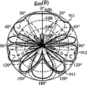
Fig. 9 A has described according to some aspect of the present invention, comprises the beam pattern of six beam patterns that generated by one dimension six cell arrays.
Fig. 9 B has described a pair of sector beam directional diagram according to some aspect of the present invention.
Figure 10 has described to form according to the wave beam of some aspect of the present invention the structure of ability information unit (IE).
Figure 11 has described according to some aspect of the present invention, for carrying out the exemplary operation of multiresolution wave beam formation.
Figure 11 A has described to carry out the example components of the operation shown in Figure 11.
Figure 12 has described according to some aspect of the present invention, for carrying out the exemplary operation of sector level training.
Figure 12 A has described to carry out the example components of the operation shown in Figure 12.
Figure 13 has described according to some aspect of the present invention, determines the exemplary operation of preferred sector in asymmetrical antenna system (AAS).
Figure 13 A has described to carry out the example components of the operation shown in Figure 13.
Figure 14 A-14D has described according to some aspect of the present invention, for determine the frame structure of preferred sector at AAS.
Figure 15 has described according to some aspect of the present invention, determines the exemplary operation of preferred sector in symmetrical antenna system (SAS).
Figure 15 A has described to carry out the example components of the operation shown in Figure 15.
Figure 16 A-16B has described according to some aspect of the present invention, for determine the frame structure of preferred sector at SAS.
Figure 17 has described according to some aspect of the present invention, comprises a pair of example of bunching of a plurality of wave beams.
Figure 18 has described, according to some aspect of the present invention, preferred sector to be divided into to the exemplary operation that wave beam is bunched.
Figure 18 A has described to carry out the example components of the operation shown in Figure 18.
Figure 19 has described according to some aspect of the present invention, the exemplary operation that carries out the training of wave beam level.
Figure 19 A has described to carry out the example components of the operation shown in Figure 19.
Figure 20 has described according to some aspect of the present invention, determines the exemplary operation of preferred wave beam in AAS.
Figure 20 A has described to carry out the example components of the operation shown in Figure 20.
Figure 21 A-21D has described according to some aspect of the present invention, for determine the frame structure of preferred wave beam at AAS.
Figure 22 has described according to some aspect of the present invention, determines the exemplary operation of preferred wave beam in SAS.
Figure 22 A has described to carry out the example components of the operation shown in Figure 22.
Figure 23 A-23B has described according to some aspect of the present invention, for determine the frame structure of preferred wave beam at SAS.
Figure 24 has described according to some aspect of the present invention, for carrying out the exemplary operation of wave beam tracking.
Figure 24 A has described to carry out the example components of the operation shown in Figure 24.
Figure 25 has described, according to some aspect of the present invention, to have the structure of the packet of follow-up control.
Figure 26 has described according to some aspect of the present invention, the exemplary operation that carries out wave beam formation from the angle of transmitter.
Figure 26 A has described to carry out the example components of the operation shown in Figure 26.
Figure 27 has described, according to some aspect of the present invention, to determine the exemplary operation of preferred emission direction from the angle of transmitter.
Figure 27 A has described to carry out the example components of the operation shown in Figure 27.
Figure 28 has described, according to some aspect of the present invention, to determine the exemplary operation of preferred emission direction from the angle of receiver.
Figure 28 A has described to carry out the example components of the operation shown in Figure 28.
Embodiment
Below in conjunction with accompanying drawing, various aspects of the present invention are more fully described.But the present invention can realize with multiple different form, and it should not be construed as limited to and run through any ad hoc structure or the function that the present invention provides.On the contrary, provide these aspects just to make the present invention become thorough and complete, and will intactly pass on protection scope of the present invention to those of ordinary skill in the art.According to teachings herein, those of ordinary skills should be understood that, protection scope of the present invention is intended to cover any aspect of the disclosed content of the application, and no matter it is independent that realize or realize in conjunction with any other side of the present invention.Can implement device or can implementation method in the aspect of any amount of for example, using the application to set forth.In addition, protection scope of the present invention is intended to cover this device or method, and this device or method can or be different from by the 26S Proteasome Structure and Function of setting forth by other structure, function or except the application the 26S Proteasome Structure and Function that the application sets forth and realize.Should be understood that, any aspect of the disclosed content of the application can embody by one or more parts of the present invention.
" exemplary " used in this application word means " as example, illustration or explanation ".Any aspect that is described to " exemplary " in the application should not be interpreted as than other side more preferably or have more advantage.
Therefore, can easily to these aspects of the present invention, make various modifications and substituting form, this paper shows particular exemplary of the present invention aspect and have been described in detail in the mode of example in the accompanying drawings.But, should be understood that, this paper is not intended to the present invention is limited to particular forms disclosed, and on the contrary, the present invention is intended to cover all modifications, equivalent and the substitute that falls into protection range of the present invention.The same tag run through in the description of accompanying drawing identifies identical unit.
Should also be noted that in the implementation substituting at some, the function marked in module/action can be not according to occurring in sequence of illustrating in flow chart.For example, according to the function related to and process, two modules that illustrate continuously in fact can carry out substantially simultaneously or these modules can be carried out sometimes in reverse order.
Exemplary wireless communication system
The technology that the application describes can be for various system of broadband wireless communication, and the latter comprises based on single carrier transmission or the communication system based on OFDM (OFDM).The disclosed aspect of the application is useful especially for the system of using ultra broadband (UWB) signal (it comprises millimeter-wave signal), wherein by using common mode (that is, using single carrier) can realize that wave beam forms.But the present invention is not intended to be limited to these systems, the signal of other coding also can benefit from similar advantage.
Fig. 1 has described the example of a wireless communication system 100, in this system 100, can use of the present invention aspect.Wireless communication system 100 can be system of broadband wireless communication.Wireless communication system 100 can provide communication for a plurality of communities 102, and each 102Dou You base station, community 104 is served.Base station 104 can be the fixed station communicated with user terminal 106.Base station 104 also can be called piconet controller (PNC), access point, Node B or certain other term.
Fig. 1 has described the various user terminals 106 in the system that is scattered in 100.User terminal 106 can be (that is, static) fixed or move.User terminal 106 also can be called distant station, accesses terminal, terminal, subscriber unit, mobile radio station, stand, subscriber equipment etc.User terminal 106 can be wireless device, for example cell phone, personal digital assistant (PDA), handheld device, radio modem, laptop computer, personal computer etc.
Many algorithms and method can be for the transmission between wireless communication system 100 base stations 104 and user terminal 106.For example, can be according to UWB technology sending and receiving signal between base station 104 and user terminal 106.If this is the case, wireless communication system 100 can be referred to as the UWB system.
Contribute to the communication link of realizing 104 transmission to user terminal 106 from base station can be referred to as down link (DL) 108, contribute to realize can be referred to as up link (UL) 110 from the communication link of user terminal 106 transmission of 104 to base station.Perhaps, down link 108 can be referred to as forward link or forward channel, and up link 110 can be referred to as reverse link or backward channel.
Community 102 can be subdivided into to a plurality of sectors 112.Physics overlay area in 112Shi community, sector 102.Base station 104 in wireless communication system 100 can be used the power stream in the particular sector 112 of plurality of antennas ,Jiang community 102 to be concentrated.These antenna can be referred to as directional antenna.
Fig. 2 has described to be used in the various assemblies in wireless device 202, and wherein wireless device 202 is used in wireless communication system 100.Wireless device 202 is can be for an example of the equipment of realizing the described the whole bag of tricks of the application.Wireless device 202 can be base station 104 or user terminal 106.
Wireless device 202 can comprise processor 204, and the latter controls the operation of wireless device 202.Processor 204 can also be referred to as CPU (CPU).The memory 206 that can comprise read-only memory (ROM) and random access memory (RAM) provides instruction and data to processor 204.The part of memory 206 can also comprise nonvolatile RAM (NVRAM).Generally, processor 204 is according to being stored in program command actuating logic and the arithmetical operation in memory 206.Instruction in can execute store 206 is to realize the described method of the application.
Wireless device 202 can also comprise housing 208, and the latter can comprise transmitter 210 and receiver 212, in order to make between wireless device 202 and remote location, can carry out transmitting and receiving of data.Transmitter 210 and receiver 212 can be combined in transceiver 214.Single or multiple transmitting antenna 216 can be connected to housing 208 and be electrically coupled to transceiver 214.Wireless device 202 can also comprise (not illustrating) a plurality of transmitters, a plurality of receiver and a plurality of transceiver.
Wireless device 202 can also comprise signal detector 218, and the latter is for detecting and quantize as possible the level of transceiver 214 received signals.Signal detector 218 can detect such as the energy of whole energy, the every symbol of every subcarrier, signal and other signal power spectral density.Wireless device 202 can also comprise the digital signal processor (DSP) 220 for the treatment of signal.
Can each assembly of wireless device 202 be coupled by bus system 222, wherein bus system 222 also comprises power bus, control signal bus and status signal bus in addition except comprising data/address bus.
The Beam Forming System model
For transmitting and receiving the transceiver that all adopts same antenna, when multipath channel is reciprocity (reciprocal) for another transceiver, it is referred to as symmetrical antenna system (SAS).Use one group of antenna launch and another group transceiver of being received of antenna or multipath channel for another transceiver be not reciprocity the time, it is referred to as asymmetrical antenna system (AAS).Fig. 3 has described the block diagram of AAS.The first transceiver 302 uses M
TIndividual transmitting antenna and M
RIndividual reception antenna.The second transceiver 304 uses N
TIndividual transmitting antenna and N
RIndividual reception antenna.
When the first transceiver 302 transmits to the second transceiver 304, can use channel model H
1 → 2Mean communication environments.Equally, when signal that transceiver 304 emission transceivers 302 receive, can use channel model H
2 → 1Mean communication environments.Can be illustrated in any possible antenna configuration used in association area with channel model.In addition, channel model can also be for meaning different host-host protocols.In one aspect of the invention, OFDM signaling with fast Fourier transform (FFT) of Cyclic Prefix and N subcarrier can be used the channel model identical with following transmission, that is: this transmission is to have the single carrier of the Cyclic Prefix that burst length is N (SC).In this case, with the multidiameter delay expansion between any a pair of send-receive antenna element, compare, generally suppose that Cyclic Prefix is longer.
OFDM symbol stream or SC burst x (t) that the first transceiver 302 generates can be expressed as:
Wherein, T
cSampling (or chip) duration, s
kMean complex data.Before symbol stream is transmitted into to communication channel, can be by weight
Wave beam form the vector symbol stream is modulated.
Multiple-input and multiple-output (MIMO) channel can mean by the frequency domain channel state information in any n frequency range (CSI), for example:

Wherein, h
I, j(n) item can comprise and transmits and receives filtering, and the channel impulse response between i reception antenna of j transmitting antenna of the first transceiver 302 and the second transceiver 304, j=1, and 2 ..., M
TAnd i=1,2 ..., N
R.
In order to generate the combined base band signal be expressed from the next, the signal that the second transceiver 304 receives can be by weight
Mix vector processed:
Wherein, b (t) is additive white Gaussian noise (AWGN) vector in the reception antenna of the second transceiver 304.
Discrete channel model between the transmitter 306 of the first transceiver and the receiver 310 of the second transceiver can be shown as by single-input single-output (SISO) channel table:
Wherein,
 I means sampling (or chip) index in OFDM sampling (or single carrier burst).The frequency range n=0 that can mean with following formula, 1 ..., the feature of SISO channel is described in the frequency response at N-1 place:
The reception signal model of discrete-frequency can be expressed as:
Y
n=P
sS
n+B
n (7)
Wherein, [S
0, S
1..., S
N-1] be OFDM data symbol (or FFT of SC data burst), [B
0, B
1..., B
N-1] be the AWGN vector.
The channel model that means channel between the receiver 308 of transmitter 312 to first transceivers 302 of the second transceiver 304 can mean with following formula:
Transmit the two for OFDM and SC, n subcarrier in the both direction of AAS (n=0,1 ..., the signal to noise ratio (SNR) on N-1) can mean with following formula:
A target of system is to determine that preferred wave beam forms vectorial w
1And w
2, preferred compositions vector c
1And c
2, so that effective SNR (ESNR) maximum retrained by the glossary of symbols of weight vectors.
The instantaneous SNR that ESNR can be defined as to the subcarrier from being meaned by formula (9) is equal to the mapping of SNR to (while considering the forward error correction (FEC) of using in system).For example exist at present, for calculating the distinct methods of ESNR: calculate the average of the SNR on a plurality of subcarriers, such as Quasi-static Method shared in third generation partner program 2 (3GPP2) and 1xEV-DV/DO (evolution data and video/data optimization) communication system, the effective SINR of index than (SINR) mapping (CESM), in can using the CESM technology based on projection tolerance in 3GPP2 and 1xEV-DV/DO system and being used in 3GPP2 shines upon (EESM) with interference plus noise also to use capacity useful signal in 3GPP2 and 1xEV-DV/DO system.
Can use different ESNR computational methods for SC and ofdm system.For example, generally, the SC equalizer based on least mean-square error (MMSE) has the ESNR that averages to be similar to out by the SNR in the difference burst.But OFDM trends towards having and carrys out the ESNR of optimal approximation by the SNR on the subcarrier to different by geometric average.For example, in order to calculate other parameter (, FEC, receiver imperfection and/or bit error rate (BER)), can also use various other ESNR computational methods.
Wave beam forms term
When the wave beam between two equipment of description forms, can use following symbol.Two equipment that communicate can be referred to as DEV 1 and DEV 2, and for example, DEV 1 can be piconet controller (PNC), and DEV 2 can be subscriber station.For DEV 1, device numbering d can be 1, and for DEV 2, device numbering d is 2.
Usually, term " accurate omni-directional pattern " is relevant to the lowest resolution directional diagram in the non-constant width zone of overlay device (DEV) object space scope on every side.PNC can be used as far as possible little accurate omni-directional pattern (may be overlapping) collection to carry out the coverage goal area of space.Equal 1 collection size and point out that PNC can carry out the coverage goal area of space by an accurate omni-directional pattern only, this explanation PNC has omni-directional capabilities.Be numbered the relevant accurate theaomni-directional transmission of DEV of d and the total quantity of receiving pattern and can be expressed as I
(d, t)And I
(d, r).Corresponding accurate theaomni-directional transmission and receiving pattern can be expressed as:
 N=0 wherein, 1 ..., I
(d, t)-1 (for transmitting pattern);
N=0 wherein, 1 ..., I
(d, r)-1 (for receiving pattern).When DEVd and other DEV communicate, for a pair of preferred accurate theaomni-directional transmission of DEV d and receiving pattern respectively by index i
(d, t)And i
(d, r)Identify.Corresponding accurate theaomni-directional transmission and receiving pattern can be expressed as
N=0 wherein, 1 ..., I
(d, t)-1 (for transmitting pattern);
N=0 wherein, 1 ..., I
(d, r)-1 (for receiving pattern).When DEVd and other DEV communicate, for a pair of preferred accurate theaomni-directional transmission of DEV d and receiving pattern respectively by index i
(d, t)And i
(d, r)Identify.Corresponding accurate theaomni-directional transmission and receiving pattern can be expressed as
 With
With
 If these two equipment are all SAS equipment, use identical aerial array owing to transmitting and receiving so, therefore can omit subscript t and r.Fig. 4 A has described two accurate omni-directional pattern Q for SAS equipment
0And Q
1Example.
If these two equipment are all SAS equipment, use identical aerial array owing to transmitting and receiving so, therefore can omit subscript t and r.Fig. 4 A has described two accurate omni-directional pattern Q for SAS equipment
0And Q
1Example.
In this application, term " sector " typically refers to the second layer class resolution ratio directional diagram in the relatively wide zone that covers a plurality of wave beams.A sector can cover one group of continuous or discrete wave beam, and different sectors can be overlapping.The associated transmissions that is numbered the DEV of d can be expressed as to J with the total quantity that receives sector
(d, t)And J
(d, r).Transmitting and receiving accordingly sector can be expressed as:
 N=0 wherein, 1 ..., J
(d, t)-1 (for the emission sector);
N=0 wherein, 1 ..., J
(d, t)-1 (for the emission sector);
 N=0 wherein, 1 ..., J
(d, r)-1 (for receiving sector).When DEV d and other DEV communicate, for a pair of preferred emission of DEV d and receive sector can be respectively by index j
(d, t)And j
(d, r)Identify.Transmitting and receiving accordingly sector can be expressed as
N=0 wherein, 1 ..., J
(d, r)-1 (for receiving sector).When DEV d and other DEV communicate, for a pair of preferred emission of DEV d and receive sector can be respectively by index j
(d, t)And j
(d, r)Identify.Transmitting and receiving accordingly sector can be expressed as
 With
With
 If these two equipment are all SAS equipment, can omit subscript t and r.Fig. 4 B has described four overlapping sector S for SAS equipment
0, S
1, S
2, S
3Example.
If these two equipment are all SAS equipment, can omit subscript t and r.Fig. 4 B has described four overlapping sector S for SAS equipment
0, S
1, S
2, S
3Example.
Sector can be subdivided into as the wave beam of high-level resolution directional diagram more.Can be expressed as K by being numbered the associated transmissions of DEV of d and the total quantity of received beam
(d, t)And K
(d, r).Transmitting and receiving accordingly wave beam can be expressed as:
 N=0 wherein, 1 ..., K
(d, t)-1 (for launching beam);
N=0 wherein, 1 ..., K
(d, t)-1 (for launching beam);
 N=0 wherein, 1 ..., K
(d, r)-1 (for received beam).When DEV d and other DEV communicate, can be respectively by index k for a pair of preferred emission and the received beam of DEV d
(d, t)And k
(d, r)Identify.Transmitting and receiving accordingly wave beam can be expressed as
N=0 wherein, 1 ..., K
(d, r)-1 (for received beam).When DEV d and other DEV communicate, can be respectively by index k for a pair of preferred emission and the received beam of DEV d
(d, t)And k
(d, r)Identify.Transmitting and receiving accordingly wave beam can be expressed as
 With
If these two equipment are all SAS equipment, can omit subscript t and r.Fig. 4 C has described eight the bean cotyledon B that have for SAS equipment
0, B
1..., B
7The example of unit 8 linear antenna arrays.
With
If these two equipment are all SAS equipment, can omit subscript t and r.Fig. 4 C has described eight the bean cotyledon B that have for SAS equipment
0, B
1..., B
7The example of unit 8 linear antenna arrays.
Can also further wave beam be subdivided into to high-resolution (HRS) wave beam as highest level resolution directional diagram.The associated transmissions that is numbered the DEV of d can be expressed as to L with the total quantity that receives the HRS wave beam
(d, t)And L
(d, r).Transmitting and receiving accordingly the HRS wave beam can be expressed as:
 N=0:L wherein
(d, t)-1 (for emission HRS wave beam);
N=0:L wherein
(d, t)-1 (for emission HRS wave beam);
 N=0:L wherein
(d, r)-1 (for receiving the HRS wave beam).When DEV d and other DEV communicate, for a pair of preferred emission of DEV d and receive the HRS wave beam can be respectively by index l
(d, t)And l
(d, r)Identify.Transmitting and receiving accordingly the HRS wave beam can be expressed as
N=0:L wherein
(d, r)-1 (for receiving the HRS wave beam).When DEV d and other DEV communicate, for a pair of preferred emission of DEV d and receive the HRS wave beam can be respectively by index l
(d, t)And l
(d, r)Identify.Transmitting and receiving accordingly the HRS wave beam can be expressed as
 With
If these two equipment are all SAS equipment, can omit subscript t and r.Fig. 4 D has described 16 the HRS wave beam H that have for SAS equipment
0, H
1..., H
15The example of unit 8 linear antenna arrays.
With
If these two equipment are all SAS equipment, can omit subscript t and r.Fig. 4 D has described 16 the HRS wave beam H that have for SAS equipment
0, H
1..., H
15The example of unit 8 linear antenna arrays.
Typically, the definition of the multiresolution of accurate omni-directional pattern, sector, wave beam and HRS wave beam has just become the multi-layer definition, and wherein each level is used a kind of antenna direction atlas.Therefore, accurate omni-directional pattern means the first antenna pattern collection, sector means second day line direction atlas, and wave beam means the third antenna direction atlas of preferably deriving from the second antenna pattern collection, and the HRS wave beam means the antenna pattern of preferred the 4th level derived from third antenna direction atlas.
For on the x axle, thering is K
xIndividual wave beam and there is K on the z axle
zThe two dimension of individual wave beam (2-D) aerial array, along the K of x axle
xIndividual wave beam can be with cumulative polar angle direction by index of zero to K
x-1 identifies, its can with x wave beam code book from selected in beam vectors 0 to K
x-1 is corresponding one by one.K along the z axle
zIndividual wave beam can be with cumulative polar angle direction by index of zero to K
z-1 identifies, its can with z wave beam code book from selected in beam vectors 0 to K
z-1 is corresponding one by one.For the each party to the 2-D aerial array with eight wave beams, made and having further illustrated in Fig. 5.
In this application, " (cluster) bunches " typically refer to one group of wave beam around a central beam.For the ease of following the tracks of preferred beam direction or being convenient under normal conditions follow the tracks of preferred antenna directional diagram (direction), introduced the concept of bunching.The quantity of bunching of each sector can be decided by the implementor.Fig. 5 has described the example of bunching of different sizes.The DEV of (PET) option can estimate and follow the tracks of for support direction figure to the coding of bunching.DEV for carrying out switched-beam and control option, do not need to support to bunch coding.Bunch and can be encoded by 8 bit field c7c6c5c4c3c2c1c0.Referring to Fig. 5,, first three minimum effective bit (that is c2c1c0) can be encoded to the wave beam in the polar angle direction, and, three bits of second group (that is c5c4c3) can be encoded to the wave beam in azimuth direction.Two bits (c7c6) of last group specify three kinds of different 2-D to puncture pattern (that is, difference bunch geometry).
Calculating and follow the tracks of preferred wave beam forms and mix vector
Some aspect of the present invention has provided for selecting antenna weight (w
1And w
2) wave beam form vector sum antenna weight (c
1And c
2) one or more beamforming algorithms of mix vector, these vectors of wherein selecting (for example, ESNR) maximize at least one signal quality parameter.In general AAS situation, the first transceiver 302 is to the second transceiver 304 emission Given informations, and subsequently, the second transceiver 304 is derived the matrix of describing channel condition information (CSI) feature.So just can calculate w
1And c
2Estimator.In order to provide, can be used for to w
2And c
1The CSI that calculated of estimator, the second transceiver 304 can be to the first transceiver 302 emission Given informations.Aspects more of the present invention obtain CSI with given data symbol, pilot signal or other training information that will launch.Substituting aspect of the present invention can adopt blind adaptive processing or other technology to derive CSI with unknown transmitting data.
In the situation that AAS, for to vectorial w
1, w
2, c
2And c
1Estimated, the both direction of link all needs to come into operation.In the situation that SAS, the wave beam in specific direction forms vectorial w
1And w
2And mix vector c
2And c
1Equate.Therefore, w
1=w
2And c
2=c
1, and only by a direction of link, carry out compute vector w
1, w
2, c
2And c
1.
Fig. 6 has described to carry out between the first transceiver and the second transceiver from the receiver angle exemplary operation 600 of wave beam formation.For example, a transceiver can be piconet controller (PNC), and another transceiver can be the piconet subscriber equipment.Form a subset of code book from the first transceiver (or first equipment) received beam at 610, the second transceivers (or second equipment).Can obtain a CSI matrix by a subset of combination code book at 620, the second equipment, this matrix can form vectorial w for the preferred wave beam of estimating the first equipment
1Preferred compositions vector c with the second equipment
2.
Code book is the matrix that comprises row or multiple row, and wherein each list shows that a wave beam forms vector or a mix vector.Therefore, each row can be corresponding with a specific beam pattern and/or beam direction.Generally, the span of these group row is whole space (that is, 360 degree).
630, can estimate and generate preferred wave beam and form vectorial w
1With preferred compositions vector c
2.Should be understood that, term " preferably wave beam forms vector " and " preferred compositions vector " mean the estimator of preferred value, be subject to the restriction in one or more processing constraints and limited processing time (it has limited the number of times of iterative computation) for the optimization of these estimators, wherein, these are processed constraints and include, but is not limited to the information loss caused due to quantification, it has simplified hypothesis, in order to sacrifice some accuracies and/or precision in order to reduce computation complexity.Can also apply other constraints.For example, aspect more of the present invention in, with respect to the subset of availability vector, can think to cause the wave beam of signal quality metrics on predetermined thresholding to form and/or mix vector is preferred.Therefore, in this application, term " preferably wave beam forms vector " is equal to preferred wave beam and forms vector.Equally, term " preferred compositions vector " is equal to preferred wave beam and forms vector.Estimating step 630 can be used Different Optimization criterion arbitrarily, for example EESM or average SNR.
640, preferred wave beam can be formed to vectorial w
1(with (optionally) preferred compositions vector c
2) send it back the first equipment.For AAS, can repeating step 610 to 640, wherein can exchange the appointment of " the first equipment " and " the second equipment ".Therefore, can also estimate that preferred wave beam forms vectorial w
2With preferred compositions vector c
1.For SAS, w
1=w
2And c
2=c
1.
Figure 26 has described to carry out between the first transceiver and the second transceiver from the transmitter angle exemplary operation 2600 of wave beam formation.Can form to the second transceiver (or second equipment) launching beam a subset of code book at 2610, the first transceivers (or first equipment).2620, once determine that at the second equipment preferred wave beam forms vectorial w
1, the preferred wave beam that the first equipment just can receive as feedback from the second equipment forms vectorial w
1.At 2630, the first equipment, can use wave beam to form vectorial w
1A transmit direction (for example, beam direction) at the transmit direction collection above communicates with the second equipment.
Fig. 7 has described for upgrading the exemplary operation 700 of wave beam formation and mix vector.710, the second equipment by with obtain the speed used during operation 610-640 Comparatively speaking lower speed come received beam to form a subset of code book.720, can upgrade preferred wave beam and form vectorial w
1With preferred compositions vector c
2.730, the wave beam after renewal forms vectorial w
1(the mix vector c after upgrading with (optionally)
2) can feed back to the first equipment.For AAS, can repeating step 710 to 730, wherein can exchange the appointment of " the first equipment " and " the second equipment ".Therefore, can also upgrade preferred wave beam and form vectorial w
2With preferred compositions vector c
1Estimator.For SAS, w
1=w
2And c
2=c
1.
Wave beam forms code book and beam pattern
For the evenly spaced linear antenna arrays with N unit, array factor can be defined as:
Wherein, d is the spacing between array element, and θ means and the angle of the axle of linear array, and λ is wavelength, w
nIt is the array element weight of n array element.The aerial array direction can mean with following formula:
Wherein,
The maximum possible directivity is D
Max=N.
The array factor of two-dimensional array can mean with following formula:
Wherein, d
xExpression is along the array pitch of x axle, d
zExpression is along the array pitch of z axle, N
xThe quantity along the unit of x axle, N
yBe the quantity along the unit of z axle, φ is the anglec of rotation with the x axle.Antenna weight w
M, nCan be expressed as w
M, n=w
X, mW
Z, n, m=0:N wherein
x-1 and n=0:N
z-1.Therefore, the antenna weight matrix can be used
 Mean.
Mean.
In one aspect of the invention, the two-dimensional antenna array can be trained by using along the code book of x axle and z axle.The array factor of two-dimensional array can be divided into to one dimension (x axle and z axle) array component, it is expressed as:
A(θ,φ)=A
x(θ,φ)·A
z(θ,φ), (14)
Wherein,
Particularly, in order to be trained, can use the two-dimentional code book of for example, deriving from one dimension code book (, x axle and z axle code book).For example, two-dimentional code book
Can use along the code book of the one dimension aerial array of x axle
 Code book with one dimension aerial array along the z axle
 Mean.For example, the two-dimensional antenna weight can be calculated according to x axle and z axle antenna weight, as:
W
M, n=w
X, mW
Z, n, m=0:N wherein
x-1 and n=0:N
z-1 (17)
Some aspect support of the present invention generates and/or uses wave beam code book and sector code book.In this application, " wave beam code book " means that a kind of quantity of wave beam therein is more than or equal to the code book of antenna amount.In this application, " sector code book " means accurate omnidirectional code book, and it comprises the wave beam that can quantity be less than antenna amount.
For using in aspect some for the wave beam code book trained of the present invention, it is enough using a pair of one dimension beam code originally to substitute two-dimentional code book.In one aspect of the invention, the wave beam codebook matrix for N antenna and M wave beam can be expressed as:

Wherein, fix () is the function that returns to the integer part of its parameter.One substituting aspect, function f ix () can substitute with function round (), wherein function round () rounds its parameter into immediate integer.Should be understood that, can carry out the element in the compute beam codebook matrix with substituting formula and function, and the aspect that the application describes is intended to illustrate example of the present invention rather than restriction the present invention.
Fig. 8 A has described four kinds of beam pattern 801-804 that generated by the four unit linear arraies corresponding with following codebook matrix:
Fig. 8 B has described six kinds of beam pattern 811-816 that generated by the four unit linear arraies that use following codebook matrix:
Use the benefit of the beam pattern shown in Fig. 8 B to be: if four cell arrays are in receiving mode, and the strongest reception sense is 45 °, beam pattern 813 (also therefore, array gain) can reach maximum in the strongest reception sense so.If used four kinds of beam patterns in Fig. 8 A, so the strongest reception signal arrives between beam pattern 801 and 802, and array gain is very low herein.
Four identical cell arrays can be used and can make it generate the substituting code book of other beam pattern.For example, Fig. 8 C has described eight kinds of beam pattern 821-828 that generated by the four unit linear arraies that use following codebook matrix:
For different angular resolutions is provided, aerial array can be used the multiple code book of the beam pattern that varied number is provided.In one aspect of the invention, at first training can be used low resolution (that is, wide) wave beam, then uses high-resolution (that is, narrow) wave beam.In some respects, broad beam can comprise a plurality of narrow beams.
When using the wave beam code book to carry out the training of two-dimensional array, can use the beam code of the one-dimensional array of x axle and z axle originally to calculate the wave beam code book of two-dimensional array.If x axle code book comprises K
xIndividual wave beam, z axle code book comprises K
zIndividual wave beam, two-dimensional array just has K so
xK
zIndividual wave beam.
For using the sector code book in some aspect of the present invention, for the sector codebook matrix of N antenna (wherein, N is even number) and M=N/2 sector, can mean with following formula:
Wherein, each sector can comprise two wave beams in the wave beam code book with N wave beam.Substituting aspect of the present invention can be provided for generating the modification of formula and the function of sector codebook matrix.For example, the fix () function in formula (22) can substitute with function round ().According to substituting application and aspect, can also carry out other variation, these are all that those of ordinary skill in the art is to understand.
Fig. 9 A has described to comprise the beam pattern of six kinds of beam pattern 901-906 that generated by six cell arrays of one dimension.The sector beam directional diagram can be by the combination wave beam to generating.For example, the first sector can comprise that beam pattern 901 and 904, the second sectors can comprise that beam pattern 902 and 905, the three sectors can comprise beam pattern 903 and 906.Therefore, sector can comprise adjacent or non-adjacent beam pattern.In addition, sector can also be overlapping.
Fig. 9 B has described a pair of sector beam directional diagram 911 and 912 of linear six element antenna arrays.Corresponding two sector code books can mean with following formula:
Of the present invention substituting aspect, the sector code book can also be provided for the situation of M ≠ N/2.
Wave beam forms Optimality Criteria
Proposed in the present invention two kinds of wave beams and formed Optimality Criterias: be applicable to all antenna configurations switched-beam (guiding, steering) and tracking (BST) criterion; The directional diagram that is only applicable to one dimension (1-D) linear antenna arrays and two dimension (2-D) planar antenna array is estimated and tracking (PET) criterion.Support all devices (DEV) of PET method also all to support BST.All support this specific PET criterion if form two DEV of communication link, so just can only use PET.
The BST criterion is independent of used antenna configuration, that is, and and the aerial array that BST can be applied to change type antenna, sectorized antennas and use multiple-input and multiple-output (MIMO) transmitting/receiving.It should be noted in the discussion above that any information of the code book that BST need to not used about particular device (DEV), that is, DEV 2 does not need the code book of knowing that DEV 1 is used, and DEV 2 does not need to know DEV 1 is used how many antennas yet.Therefore, BST means to be applicable to any antenna configuration and forms criterion about the wave beam of any quantity available information of other DEV.BST criterion each level based on forming at wave beam is selected the preferred orientations atlas, and based on follow the tracks of preferred orientations figure during tracking phase.On the other hand, the PET criterion is based on finding preferred Beam-former and combiner vector (that is, antenna weight), and these vectors needn't fall into given beam direction atlas.
Wave beam forms agreement
Some aspect of the present invention supports two kinds of wave beams to form agreement: wave beam forms agreement and active beam formation agreement as required.Wave beam forms and can occur in the channel time allocation period (CTAP) of distributing to DEV as required.DEV 1 can retain a CTAP, to be specifically designed to the wave beam formation of another equipment DEV2, obtains.In active beam forms, the sector level is trained the sector training section in the beacon part that occurs in superframe.For example, as shown in figure 10, the number of sectors of DEV can form in ability information unit (IE) and specify at wave beam.DEV can be during association process or afterwards, sends its wave beam to piconet controller (PNC) and forms ability IE.PNC can broadcast beam form ability IE or by its relaying to being ready any miscellaneous equipment communicated with this DEV.Follow after the training of sector level and the training of wave beam level, message can occur to PNC with in the wave beam formation CTAP of DEV distribution.
In the situation that wave beam forms as required, DEV 1 forms in order with DEV 2, to carry out wave beam, and it can the request service cycle (SP).Can distribute special-purpose stream index for this SP.Can form in ability information unit (IE) at wave beam, broadcast SP with DEV 1 together with DEV 2 wave beams formation abilities and distribute.Figure 10 illustrates the example that wave beam forms ability IE structure.
Wave beam forms omnidirectional and the number of sectors that ability IE can specify transmitting and receiving apparatus.For some aspect of the present invention, if field " the accurate omnidirectional of #Tx " equals 1, equipment can carry out theaomni-directional transmission so.In addition, if field " the accurate omnidirectional of #Rx " equals 1, this equipment can carry out omnidirectional's reception so.For some aspect of the present invention, if " aerial array type " field equals 0, can use the change type antenna so, if " aerial array type " field equals 1, can use sectorized antennas so, if this field equals 2, can use so antenna distance for half one dimension (1-D) linear antenna arrays of wavelength, if this field equals 3, can use so antenna distance for half two dimension (2-D) linear antenna arrays of wavelength.The value 4 of " aerial array type " field can not specified, and value 5-7 retains.
Wave beam forms maximum quantity that wave beam that ability IE can comprise that each equipment can be supported forms level for information about.Wave beam forms transmitting antenna and the reception antenna quantity that ability IE can also specify transmitting and receiving apparatus." PET " field indication that wave beam forms ability IE does not need to use directional diagram estimation and trace routine based on code book to carry out wave beam formation.As shown in Figure 10, can also provide and follow the tracks of support.
The multiresolution wave beam forms
Generally, there is for example two-dimentional transmitter array of 8 * 8=64 unit and launch 64 training sequences in formed the code book appointment by 8 * 8 wave beams 64 different directions.There is for example each in 36 different combinations of directions receive 64 transmitting sequences of two-dimentional array acceptor of 6 * 6=36 unit.Therefore, need 64 * 36=2304 training sequence to identify preferred emission/received beam pair.This process has the not large processing delay of tolerable.A kind of method that wave beam forms is supported in some aspect of the present invention, and the method is used multiresolution, and it has reduced computation complexity and processing delay that wave beam forms.
For some aspect of the present invention, transmitter can use along a plurality of sector pattern of each axle in x axle and z axle.Each sector pattern can comprise a plurality of narrower x axles and z axle beam pattern.Once determine preferred sector pattern, just can determine preferred narrow wave beam in this sector.Therefore, can greatly reduce identification preferred emission/received beam to and the training sequence quantity that needs.
Figure 11 has described the exemplary operation 1100 formed for the multiresolution wave beam.Before carrying out the wave beam formation processing, the first equipment and the second equipment can exchange aerial array information (not shown), for example: along the antenna amount of z axle, along the antenna amount of x axle, the number of sectors that the first equipment and the second equipment will be used during coarseness is obtained, the code book sign (or number of beams) that will use at wave beam level training period, following the tracks of during processing the code book sign (or HRS number of beams) that will use.In addition, before wave beam formation processing each time, before data session each time, the first equipment and the second equipment can exchange quantity that one or more wave beams that this concrete data session will use form levels for information about.
Lift an exemplary situation, the first equipment (for example, the piconet controller) and the second equipment (for example, subscriber equipment) all have the 1-D linear array of eight unit, and use identical sectorization.When the second equipment and PNC carry out when associated, these two equipment can exchange following message: along the antenna amount (N of z axle
z=8), along the antenna amount (N of x axle
x=1), equal 2 number of sectors, equal 8 number of beams, equal 32 HRS number of beams, the information of bunching (for example, bunch for one and comprise a wave beam, a wave beam equals four HRS wave beams) for following the tracks of.
1110, according to certain signal quality metrics, the first equipment and the second equipment can be selected at least one preferred sector pattern, with for transmitting/receiving.This selection processing procedure can be referred to as coarseness and obtain processing procedure.Each sector pattern can comprise a plurality of beam patterns.For example, the one or more sectors for emission can be identified as in receiver one side (being weighed by the combination in any of signal quality or performance metric) optimum signal is provided.
Beam pattern in can the sector that each is selected is grouped into a plurality ofly bunches.Like this, each is bunched and can comprise a plurality of adjacent beams directional diagrams along x axle and z axle, and each sector comprises one or morely bunches.Bunch and can comprise the wave beam in the sector selected by the combination in any of signal quality or performance metric.
At 1120, the first equipment and the second equipment, can select for emission and at least one preferred beam pattern for receiving.This selection processing procedure can be referred to as essence and obtain processing procedure, and it can also comprise by the combination in any of signal quality or performance metric selects one or morely preferably to bunch.By signal quality or performance metric, (for example, combination in any ESNR) is selected one or more wave beams, with for data communication.For some aspect of the present invention, for more than one different path is provided between the equipment of just communicating by letter, can be intentionally at the non-adjacent preferred wave beam of middle selection of bunching.This is especially favourable in following situation, that is: the preferably beam direction strong loss of experience suddenly, and, in order to maintain the path that signal quality need to be alternative.
Follow the tracks of at least one preferred beam pattern for transmitting and receiving at 1130, the first equipment and the second equipment.The wave beam that tracking can also be used HRS wave beam code book to provide, wherein, compare with conventional wave beam, and the HRS wave beam can provide higher resolution.Can be to each selected distribution HRS wave beam of bunching, to follow the tracks of for low rate.Any combination that can the serviceability standard is upgraded using the selection of which HRS wave beam, can by with transfer of data Comparatively speaking lower speed carry out termly this processing procedure that reappraises.
Figure 27 has described, according to some aspect of the present invention, to determine the exemplary operation of preferred emission direction from the transmitter angle.2710, can use the first transmit direction collection to an equipment transmitting training signal.2720, can receive the indication of at least one the first preferred emission direction from this equipment, wherein, described at least one first preferred emission direction derives from the first transmit direction collection.2730, can use the second transmit direction collection to this equipment transmitting training signal, wherein the second transmit direction collection is derived from least one first preferred emission direction.2740, can receive the indication of at least one the second preferred emission direction from this equipment, wherein, described at least one second preferred emission direction derives from the second transmit direction collection.2750, by described at least one second emission preferred orientations, come to communicate with this equipment.
Figure 28 has described, according to some aspect of the present invention, to determine the exemplary operation of preferred emission direction from the receiver angle.2810, can receive the training signal that uses the first transmit direction collection emission from an equipment.2820, can derive the preferred emission direction from the first transmit direction collection.2830, the indication of preferred emission direction is provided to this equipment, using as the feedback to this equipment, wherein this feedback provides by scanning the second transmit direction collection.
Figure 12 has described according to some aspect of the present invention, carries out the exemplary operation 1200 of quadravalence section sector level training.1210, can carry out the training of sector, to determine at least one preferred sector.1220, can send the feedback information about at least one preferred sector to another equipment.Afterwards, 1230, can carry out sector-wave beam mapping, described at least one preferred sector map is arrived to wave beam.For example, can realize mapping by described at least one preferred sector being cut into to some wave beams.The mapping message that sends to another equipment can comprise the quantity that transmits and receives beam direction of using in the training of wave beam level about this particular device.Finally, 1240, in order to confirm to receive mapping message, can be from this equipment feedback acknowledgment information.
It should be noted in the discussion above that operation 1200 means the logical partitioning of sector level training stages, that is: the communication period on physical radio channel can be combined some in these stages.For example, follow after the sector level training stage from DEV 1 to DEV 2, part from DEV 2 to DEV that can be using feedback and mapping message as 1 training sequence of launching from (that is, as the sector level training stage 1210 from DEV 2 to DEV 1 a part) sends to DEV 1 from DEV 2 in combination.
Figure 13 has described to determine the exemplary operation 1300 of preferred sector in asymmetrical antenna system (AAS), and Figure 14 A-14D has described the frame structure of broadcasting during training and feedback stage.Operation 1300 can also be corresponding with the step 1110 in Figure 11.Step 1302-1312 can be corresponding with the sector training stage 1210 in Figure 12, and step 1314-1320 can be corresponding with feedback stage 1220.In the situation that without loss of generality, can suppose, equipment can be transmitted and received with the two-dimensional antenna array.The total quantity that transmits and receives antenna element that is numbered the DEV of d equals respectively M
(d, t)And M
(d, r).Each equipment can be selected its oneself sector code book.Each equipment can, according to the predetermined quantity of antenna amount and wave beam, be selected its wave beam code book.
1302, also as shown in Figure 14 A, the first equipment can be used J
(1, t)Individual sector is at J
(1, t)Transmitting training sequence sets in individual circulation.For the second equipment, each training sequence of training sequence collection is known, and these sequences can be based on a pair of Gray's sequence.Transmission in each circulation can be included in the J sent in the same transmit sector of the first equipment
(2, r)Individual training sequence, with institute in the second equipment, likely to receive sector corresponding for it.Can use J at 1304, the second equipment in each cycle period
(2, r)Individual different sector receives these training sequences.1306, according to received training sequence, at least one that can determine the second equipment preferably receives sector directions, can also determine at least one preferred emission sector directions of the first equipment.Can determine preferred sector by the combination in any of signal quality or performance metric.For some aspect of the present invention, 1302, can use the J in each circulation
(1, t)Individual different emission sector, launch the J each circulation from the first equipment
(1, t)Individual training sequence.Can use J at 1304, the second equipment
(2, r)Individual different of receiving in sector, receive all J in a circulation
(1, t)Individual training sequence.In each follow-up circulation, the second equipment can be used new reception sector, at J
(2, r)After individual circulation, can use all J of the second equipment
(2, r)Individual reception sector.
1308, as shown in Figure 14B, the second equipment can be used J
(2, t)Individual sector, at J
(2, t)Transmitting training sequence sets in individual circulation.Each training sequence of training sequence collection is known for the first equipment, and these sequences can be based on a pair of Gray's sequence.Transmission in each circulation can be included in the J sent in the same transmit sector of the second equipment
(1, r)Individual training sequence, with institute in the first equipment, likely to receive sector corresponding for it.Can use J at 1310, the first equipment in each cycle period
(1, r)Individual different sector receives these training sequences.1312, according to received training sequence, at least one that can determine the first equipment preferably receives sector directions, can also be identified at least one preferred emission sector directions of the second equipment.Can determine preferred sector by the combination in any of signal quality or performance metric.For some aspect of the present invention, 1308, can use the J in each circulation
(2, t)Individual different emission sector, launch the J each circulation from the second equipment
(2, t)Individual training sequence.Can use J at 1310, the first equipment
(1, r)Individual different of receiving in sector, receive all J in a circulation
(2, t)Individual training sequence.In each follow-up circulation, the first equipment can be used new reception sector, at J
(1, r)After individual circulation, can use all J of the first equipment
(1, r)Individual reception sector.
1314, also as shown in Figure 14 C, the first equipment can be by being used J
(1, t)Individual sector
 Carry out J
(1, t)Inferior transmitting feedback message, the information with feedback about at least one preferred emission sector directions of the second equipment.1316, as shown in Figure 14 C, the second equipment can be used preferred reception sector
Carry out J
(1, t)Inferior transmitting feedback message, the information with feedback about at least one preferred emission sector directions of the second equipment.1316, as shown in Figure 14 C, the second equipment can be used preferred reception sector
 Reception and decoding are about the information of at least one preferred emission sector directions.For some aspect of the present invention, when the first equipment has omni-directional capabilities, can not need to scan all emissions sector.1318, as shown in Figure 14 D, the second equipment is by being used the preferred emission sector
Transmitting feedback message, feed back the information about at least one preferred emission sector directions of the first equipment.1320, as shown in Figure 14 D, the first equipment can be used it preferably to receive sector
Reception and decoding are about the information of at least one preferred emission sector directions.For some aspect of the present invention, when the first equipment has omni-directional capabilities, can not need to scan all emissions sector.1318, as shown in Figure 14 D, the second equipment is by being used the preferred emission sector
Transmitting feedback message, feed back the information about at least one preferred emission sector directions of the first equipment.1320, as shown in Figure 14 D, the first equipment can be used it preferably to receive sector
 Receive and the information of decoding about at least one preferred emission sector directions.
After feedback stage finishes, two equipment have all been known their preferred emission and have received sector.As shown in the step 1230 in Figure 12, the mapping stage can follow after feedback stage.In this stage, an equipment can and receive sector map to wave beam by preferred emission, and sends relevant information to another equipment.After successfully receiving this information, another equipment can feeding back confirmation message, as shown in the step 1240 in Figure 12.
Figure 15 has described to determine the exemplary operation of preferred sector in symmetrical antenna system (SAS), and Figure 16 A-16B has described the frame structure of broadcasting during training and feedback stage.Operation 1500 can also be corresponding with the step 1110 in Figure 11.Step 1510-1530 can be corresponding with the sector training stage 1210 in Figure 12, and step 1540-1550 can be corresponding with feedback stage 1220.In the situation that without loss of generality, can again suppose, equipment can be transmitted and received with the two-dimensional antenna array, and each equipment is transmitted and received with identical aerial array.The first equipment can comprise having N
x* N
z=M
(1)The two-dimensional antenna array of individual unit, the second equipment comprises having M
x* M
z=M
(2)The two-dimensional antenna array of individual unit.For this aspect of the present invention, J
(1)Indicate the number of sectors of the first equipment, J
(2)Indicate the number of sectors of the second equipment.Each equipment can be selected its oneself sector code book.Each equipment can, according to the predetermined quantity of antenna amount and wave beam, be selected its wave beam code book.
1510, as shown in Figure 16 A, the first equipment can be used J
(1)Individual sector is at J
(1)Transmitting training sequence sets in individual circulation.Each training sequence of training sequence collection is known for the second equipment, and these sequences can be based on a pair of Gray's sequence.Transmission in each circulation can be included in the J sent in the common sector of the first equipment
(2)Individual training sequence, its with in the second equipment the institute likely sector is corresponding.Can use J at 1520, the second equipment in each cycle period
(2)Individual different sector receives these training sequences.1530, according to received training sequence, can determine at least one preferred sector directions of the second equipment, can also determine at least one preferred sector directions of the first equipment.Can determine preferred sector by the combination in any of signal quality or performance metric.For some aspect of the present invention, 1510, can use the J in each circulation
(1)Individual different sector, launch the J each circulation from the first equipment
(1)Individual training sequence.Can use J at 1520, the second equipment
(2)In individual sector one, receive all J in a circulation
(1)Individual training sequence.In each follow-up circulation, the second equipment can be used new reception sector, at J
(2)After individual circulation, can use all J of the second equipment
(2)Individual sector.
1540, as shown in Figure 16 B, the second equipment can be by being used its preferred sector
Carry out J
(1)Inferior transmitting feedback message, the information with feedback about at least one preferred sector directions of before having determined of the first equipment.1550, as shown in Figure 16 B, the first equipment can be used J
(1)Individual sector
 Reception and decoding are about the information of at least one preferred sector directions.
After feedback stage finishes, two equipment have all been known their preferred sector.As shown in the step 1230 in Figure 12, the mapping stage can follow after feedback stage.In this stage, an equipment can be bunched preferred sector map and be mapped to beam pattern to wave beam, can also send relevant information to another equipment.After successfully receiving this information, another equipment can feeding back confirmation message, as shown in the step 1240 in Figure 12.
Figure 17 has described a kind of exemplary situation, and in this case, equipment is selected two preferred sectors, and these sectors are divided into and bunch 1710 and 1720.Each is bunched and can comprise a plurality of wave beams.As shown in figure 17, the application uses " bunching " can refer to one group of adjacent wave beam.This equipment can also be used the wave beam code book so that these wave beams are mapped to sector.
Figure 18 has described the part as the mapping stage 1230 in Figure 12, and preferred sector is divided into to the exemplary operation 1800 that wave beam is bunched.Its preferred emission can be divided into at least one wave beam with the reception sector at 1810, one equipment bunches.1820, this equipment can send feedback information to miscellaneous equipment, and it comprises: which the quantity of the quantity of bunching, each middle wave beam of bunching, the code word identifier of each middle wave beam of bunching, which wave beam belong to and bunch.
1830, miscellaneous equipment also can be divided at least one wave beam with the reception sector by its preferred emission and bunch, 1840, it can notify this equipment about following information: the code word identifier of the quantity of bunching that will use during wave beam obtains, the number of beams that each is bunched, the wave beam in each is bunched.
Figure 19 has described according to some aspect of the present invention, carries out the exemplary operation 1900 of quadravalence section wave beam level training.1910, can carry out wave beam and train to determine at least one preferred wave beam.1920, can send the feedback information about at least one preferred wave beam to another equipment.Afterwards, 1930, can carry out wave beam-HRS wave beam mapping, described at least one preferred wave beam is mapped to the HRS wave beam.For example, can realize mapping by described at least one preferred sector being cut into to some wave beams.The mapping message that sends to another equipment can comprise the quantity about this particular device spendable HRS of transmitting and receiving beam direction during tracking phase.Finally, 1940, in order to confirm to receive mapping message, can be from this equipment feedback acknowledgment information.
It should be noted in the discussion above that operation 1900 means the logical partitioning of wave beam level training stages, that is: the communication period on physical radio channel can be combined some in these stages.For example, follow after the wave beam level training stage 1910 from DEV 1 to DEV 2, part from DEV 2 to DEV that can be using feedback and mapping message as 1 training sequence of launching from (that is, as wave beam level training stage 1910 of 1 from DEV2 to DEV a part) sends to DEV 1 from DEV 2 in combination.
Figure 20 has described for determine the exemplary operation 2000 of the preferred wave beam in sector at AAS, and Figure 21 A-21D has described the frame structure of broadcasting during training and feedback stage.Operation 2000 can also be corresponding with the step 1120 in Figure 11.Step 2002-2012 can be corresponding with the wave beam training stage 1910 in Figure 19, and step 2014-2020 can be corresponding with feedback stage 1920.
2002, as shown in Figure 21 A, the first equipment can be used K
(1, t)Individual wave beam is at K
(1, t)Transmitting training sequence sets in individual circulation.Each training sequence of training sequence collection is known for the second equipment, and these sequences can be based on a pair of Gray's sequence.Transmission in each circulation can be included in the K sent in the same transmit wave beam of the first equipment
(2, r)Individual training sequence, its with in the second equipment the institute likely received beam is corresponding.Can use K at 2004, the second equipment in each cycle period
(2, r)Individual different wave beam receives these training sequences.2006, according to received training sequence, can determine at least one preferred received beam of the second equipment, can also determine at least one preferred emission wave beam of the first equipment.Can determine preferred wave beam by the combination in any of signal quality or performance metric.For some aspect of the present invention, 2002, can use the K in each circulation
(1, t)Individual different sector, launch the K each circulation from the first equipment
(1, t)Individual training sequence.Can use K at 2004, the second equipment
(2, r)In individual received beam one, receive all K in a circulation
(1, t)Individual training sequence.In each follow-up circulation, the second equipment can be used new received beam, at K
(2, r)After individual circulation, use all K of the second equipment
(2, r)Individual received beam.
2008, as shown in Figure 21 B, the second equipment can be used K
(2, t)Individual wave beam, at K
(2, t)Transmitting training sequence sets in individual circulation.Each training sequence of training sequence collection is known for the first equipment, and these sequences can be based on a pair of Gray's sequence.Transmission in each circulation can be included in the K sent in the same transmit wave beam of the second equipment
(1, r)Training sequence, its with in the first equipment the institute likely received beam is corresponding.Can use K at 2010, the first equipment in each cycle period
(1, r)Individual different wave beam receives these training sequences.2012, according to received training sequence, can determine at least one preferred received beam direction of the first equipment, can also determine at least one preferred emission beam direction of the second equipment.Can determine preferred wave beam by the combination in any of signal quality or performance metric.For some aspect of the present invention, 2008, can use the K in each circulation
(2, t)Individual different launching beam, launch the K each circulation from the second equipment
(2, t)Individual training sequence.The first equipment can be used K
(1, r)In individual received beam one, receive all K in a circulation
(2, t)Individual training sequence.In each follow-up circulation, the first equipment can be used new received beam, at K
(1, r)After individual circulation, can use all K of the first equipment
(1, r)Individual received beam.
2014, as shown in Figure 21 C, the first equipment can be by being used the preferred emission sector of selecting in the training of sector level
 Carry out transmitting feedback message, the information with feedback about at least one preferred emission beam direction of the second equipment.2016, as shown in Figure 21 C, the second equipment can be used preferred reception sector
 Reception and decoding are about the information of at least one preferred emission beam direction.2018, as shown in Figure 21 D, the second equipment is by being used the preferred emission wave beam
 Perhaps use the preferred emission sector of selecting in the training of sector level
Transmitting feedback message, feed back the information about at least one preferred emission beam direction of the first equipment.Can use the preferred received beam as shown in Figure 21 D at 2020, the first equipment
Perhaps use the preferred emission sector of selecting in the training of sector level
Transmitting feedback message, feed back the information about at least one preferred emission beam direction of the first equipment.Can use the preferred received beam as shown in Figure 21 D at 2020, the first equipment
 Perhaps use the preferred reception sector of selecting in the training of sector level
 Receive and the information of decoding about at least one preferred emission beam direction.
After feedback stage finishes, two equipment have all been known their preferred emission and received beam.As shown in the step 1930 in Figure 19, the mapping stage can follow after feedback stage.In this stage, an equipment can be mapped to the high-resolution wave beam by preferred emission and received beam, and sends relevant information to another equipment.After successfully receiving this information, another equipment can feeding back confirmation message, as shown in the step 1940 in Figure 19.
Except determining in two equipment in the wave beam acquisition process preferred wave beam, the first equipment can also be adjusted the quantity of one or more wave beams in bunching, and these variations are sent to the second equipment.For example, the first equipment can reduce the quantity of each middle wave beam of bunching.The first equipment can be launched this information with its preferred emission wave beam.The second equipment can receive this information with its preferred received beam, and feeding back confirmation message.
Figure 22 has described to be identified for the exemplary operation of the preferred wave beam of transmitting/receiving in SAS, and Figure 23 A-23B has described the frame structure of broadcasting during training and feedback stage.Operation 2200 can also be corresponding with the step 1120 in Figure 11.Step 2210-2230 can be corresponding with the wave beam training stage 1910 in Figure 19, and step 2240-2250 can be corresponding with feedback stage 1920.For this aspect of the present invention, K
(1)Indication is for the number of beams of the first equipment, K
(2)Indication is for the number of beams of the second equipment.
2210, as shown in Figure 23 A, the first equipment can be used K
(1)Individual wave beam is at K
(1)Transmitting training sequence sets in individual circulation.Each training sequence of training sequence collection is known for the second equipment, and these sequences can be based on a pair of Gray's sequence.Transmission in each circulation can be included in the K sent in the same beam of the first equipment
(2)Individual training sequence, its with in the second equipment the institute likely wave beam is corresponding.Can use K at 2220, the second equipment in each cycle period
(2)Individual different wave beam receives these training sequences.2230, according to received training sequence, can determine at least one preferred beam direction of the second equipment, can also determine at least one preferred beam direction of the first equipment.Can determine preferred wave beam by the combination in any of signal quality or performance metric.For some aspect of the present invention, 2210, can use the K in each circulation
(1)Individual different wave beam, launch the K each circulation from the first equipment
(1)Individual training sequence.The second equipment can be used K
(2)In individual wave beam one, receive all K in a circulation
(1)Individual training sequence.In each follow-up circulation, the second equipment can be used new wave beam, at K
(2)After individual circulation, use all K of the second equipment
(2)Individual wave beam.
2240, as shown in Figure 23 B, the second equipment can be by being used the preferred sector of selecting in the training of sector level
Carry out transmitting feedback message, the information with feedback about at least one preferred beam direction of before having determined of the first equipment.2250, as shown in Figure 23 B, the first equipment can be used the preferred sector of selecting in the training of sector level
 Receive and the information of decoding about at least one preferred beam direction.
After feedback stage finishes, two equipment have all been known their preferred wave beam.As shown in the step 1930 in Figure 19, the mapping stage can follow after feedback stage.In this stage, an equipment can be mapped to the high-resolution wave beam by preferred wave beam, and sends relevant information to another equipment.After successfully receiving this information, another equipment can feeding back confirmation message, as shown in the step 1940 in Figure 19.
Figure 24 has described the exemplary operation 2400 of following the tracks of for wave beam, and Figure 25 has described to have the structure of the grouping of follow-up control.Operation 2400 can also be corresponding with the step 1130 in Figure 11.The first equipment can be for dividing into groups to the second equipment sending data, and wherein the first equipment and the second equipment include aerial array.The wave beam that operation 2400 can be applied in SAS is followed the tracks of, and the first equipment and the second equipment preferred emission wave beam separately and the preferably tracking of received beam in AAS.Term " the first equipment " and " the second equipment " also can exchange in the case, operate 2400 and can be applied to the second equipment and the first equipment preferred emission wave beam separately and the preferably tracking of received beam.Can also carry out trace routine providing on the high-resolution wave beam of highest resolution, to upgrade the preferred orientations for transmitting and receiving.
Can build a plurality of tracking groupings at 2410, the first equipment, each is followed the tracks of in grouping has a wave beam to follow the tracks of bit, in order to indicate each to follow the tracks of grouping, comprises the training sequence for being followed the tracks of.For example, wave beam is followed the tracks of the grouping that bit is made as " 1 " and is pointed out that this grouping is one and follows the tracks of grouping.Figure 25 shows an example of this packet configuration.For example, comprising that the tracking grouping 2510 of wave beam tracking bit can comprise training sequence (TS) 2512, is then guard time (GT) time slot 2514 and packet 2516.
Can launch L at 2420, the first equipment
(2, r)Individual tracking grouping, wherein L
(2, r)It is the number of beams during one of the second equipment is bunched.Can use preferred wave beam
 Launch all L from the first equipment
(2, r)Individual data grouping (following the tracks of
Launch all L from the first equipment
(2, r)Individual data grouping (following the tracks of grouping 2510 and 2520 packet 2516 and 2526 separately in Figure 25), used the wave beam of one of the first equipment in bunching
 Launch all L
(2, r)Individual training sequence (
Launch all L
(2, r)Individual training sequence ( training sequence 2512 and 2522 in Figure 25).Can use preferred wave beam at 2430, the second equipment
 Receive L
(2, r)The grouping of individual data, and use this all L in bunching
(2, r)Individual wave beam receives L
(2, r)Individual training sequence.
Receive L
(2, r)The grouping of individual data, and use this all L in bunching
(2, r)Individual wave beam receives L
(2, r)Individual training sequence.
Can repeat above-mentioned processing procedure for each wave beam in the bunching of the first equipment.At L
(1, t)After individual circulation, L wherein
(1, t)Be the entire quantity of the middle wave beam of bunching of the first equipment, at 2440, the first equipment, can use preferred wave beam
 Launch L
(2, r)Individual data grouping (following the tracks of
Launch L
(2, r)Individual data grouping (following the tracks of grouping 2530 and 2540 packet 2536 and 2546 separately in Figure 25), used this wave beam in bunching
 Launch all L
(2, r)Individual training sequence (
Launch all L
(2, r)Individual training sequence ( training sequence 2532 and 2542 in Figure 25).Then, can use preferred wave beam at 2450, the second equipment
 Receive L
(2, r)The grouping of individual data, and use this all L in bunching
(2, r)Individual wave beam receives L
(2, r)Individual training sequence.
Receive L
(2, r)The grouping of individual data, and use this all L in bunching
(2, r)Individual wave beam receives L
(2, r)Individual training sequence.
Can determine a pair of preferred wave beam at 2460, the second equipment, with for the first equipment and the second equipment.If compare with the current a pair of preferred wave beam for data transmission/reception, this a pair of specific wave beam has signal quality preferably, bunching around 2470, the second equipment can be reformed new preferably wave beam so, and send the feedback information about this pair of preferred wave beam to the first equipment.Can receive information to preferred wave beam about this at 2480, the first equipment, be transformed into new preferred wave beam to carry out transfer of data, bunching around the preferred wave beam of the renewing of laying equal stress on.New number of beams in 2490, the first equipment can be notified bunching of the reformation of the second equipment at the first equipment.Follow the tracks of and divide into groups for many groups, can repeating step 2420-2490.
Protection scope of the present invention should not be interpreted as being subject to the restriction of the ARRAY PROCESSING aspect shown in the application.On the contrary; the applicant is contemplated that; substituting aspect can comprise: have the aerial array that surpasses eight unit and the aerial array that comprises the antenna with multiple polarization along specific axle, and these antenna array configurations also falls into protection scope of the present invention.In one aspect, two dipole antennas with orthogonal linear polarization can use together, to generate accurate omni-directional pattern.
The various operations of method mentioned above can be realized by any appropriate ways that can carry out corresponding function.These modes can comprise various hardware and/or component software and/or module, and it includes but not limited to: circuit, application-specific integrated circuit (ASIC) (ASIC) or processor.Usually, shown in the drawings have these operations in the place of operation can have the matching module functional unit corresponding with similar numbering.For example, at Fig. 6, 7, 11, 12, 13, 15, 18, 19, 20, 22, 24, 26, module 610-640 shown in 27 and 28, 710-730, 1110-1130, 1210-1240, 1302-1320, 1510-1550, 1810-1840, 1910-1940, 2002-2020, 2210-2250, 2410-2490, 2610-2630, 2710-2750 and 2810-2830 can with Fig. 6 A, 7A, 11A, 12A, 13A, 15A, 18A, 19A, 20A, 22A, 24A, 26A, circuit module 610A-640A shown in 27A and 28A, 710A-730A, 1110A-1130A, 1210A-1240A, 1302A-1320A, 1510A-1550A, 1810A-1840A, 1910A-1940A, 2002A-2020A, 2210A-2250A, 2410A-2490A, 2610A-2630A, 2710A-2750A is corresponding with 2810A-2830A.
As used in this application, term " is determined " and is comprised a variety of actions.For example, " determine " and can comprise calculating, computing, processing, derivation, investigation, inquiry (for example, inquiring about) in table, database or other data structure, conclude etc.In addition, " determining " can also comprise reception (for example, reception information), access (for example, the data in reference to storage) etc.In addition, " determine " and can also comprise and solve, select, select, set up etc.
The various operations of method mentioned above can be carried out by any suitable module that can realize these operations, for example various hardware and/or component software, circuit and/or module.Typically, in any operation shown in each accompanying drawing, can be carried out by the corresponding function module that can realize these operations.
For carrying out general processor, digital signal processor (DSP), application-specific integrated circuit (ASIC) (ASIC), field programmable gate array signal (FPGA) or other programmable logic device (PLD), discrete gate or transistor logic device, discrete hardware components or its combination in any of the described function of the application, can realize or carry out various exemplary logic diagram, module and circuit in conjunction with the disclosed content description of the application.General processor can be microprocessor, or this processor can be also any business available processors, controller, microcontroller or state machine.Processor can also be embodied as the combination of computing equipment, for example, and the combination of the combination of DSP and microprocessor, multi-microprocessor, one or more microprocessor and DSP kernel, or any other this kind of structure.
Can directly be presented as hardware, software module or the two combination carried out by processor in conjunction with the method for the disclosed content description of the application or the step of algorithm.Software module can be arranged in any type of storage medium known in the art.More operable exemplary storage medium comprise: random access memory (RAM), read-only memory (ROM), flash memory, eprom memory, eeprom memory, register, hard disk, mobile disk, CD-ROM etc.Software module can comprise single instruction or a plurality of instruction, and these instructions can be distributed on some different code segments, be distributed in the neutralization of different program and be distributed in a plurality of storage mediums.Storage medium can be coupled to processor, thereby makes the processor can be from this read information, and can be to this storage medium writing information.Perhaps, storage medium can be also the part of processor.
The disclosed method of the application comprises one or more step or actions that realize described method.On the basis that does not break away from protection range of the present invention, these method steps and/or action can exchange mutually.In other words, except step or the action of non-designated particular order, otherwise, on the basis that does not break away from protection range of the present invention, can revise order and/or the use of particular step and/or action.
The described function of the application can realize by the mode of hardware, software, firmware or their combinations.When using software to realize, these functions can be stored in computer-readable medium as one or more instructions.Storage medium can be any usable medium that computer can access.By way of example rather than the mode of restriction, this computer-readable medium can comprise RAM, ROM, EEPROM, CD-ROM or other optical disc storage, magnetic disk storage medium or other magnetic storage apparatus or can be used in the instruction of carrying or storing expectation or the program code of data structure form can be carried out by computer any other medium of access.As used in this application, dish and dish comprise compression laser disc (CD), compact video disc, laser disc, digital universal laser disc (DVD), floppy disk and Blu-ray Disc, its mid-game (disk) is copy data magnetically usually, and dish (disc) carrys out copy data optically with laser.
Therefore, some aspect can comprise for carrying out the computer program of these given operations of the application.For example, the computer-readable medium of the instruction that this computer program can comprise storage thereon (and/or coding), can carry out these instructions to realize described these operations of the application by one or more processors.For some aspect, computer program can comprise encapsulating material.
In addition, software or instruction can also be transmitted on transmission medium.For example, if software be use coaxial cable, optical fiber cable, twisted-pair feeder, Digital Subscriber Line (DSL) or the wireless technology such as infrared ray, wireless and microwave from website, server or the transmission of other remote source, coaxial cable, optical fiber cable, twisted-pair feeder, DSL or the wireless technology such as infrared ray, wireless and microwave are included in the definition of transmission medium so.
In addition, should be understood that, for module and/or other appropriate ways of carrying out the described method of the application and technology, can be downloaded desirably and/or obtain by user terminal and/or base station.For example, this equipment can be coupled to server, in order to contribute to realize transmitting the module of carrying out the described method of the application.Perhaps, the described the whole bag of tricks of the application can be by memory module (for example, RAM, ROM, the physical storage medium such as compact disk (CD) or floppy disk etc.) provide, while making user terminal and/or base station that memory module is coupled to or offers this equipment, can obtain the whole bag of tricks.In addition, can also use any other proper technology that the described method of the application and technology are provided to equipment.
Should be understood that accurate configuration and assembly that the present invention is not limited to above illustrate.Do not breaking away from protection range of the present invention basis, can make various modifications, change and variation to arrangement, operation and the details of method and apparatus mentioned above.
The technology that the application provides can be used in multiple application.For some aspect, the technology that the application provides can be incorporated in the wireless device of access point or other type, and the wireless device of these access points or other type has for carrying out processing logic and the unit of technology that the application provides.
Claims (53)
1. the method for radio communication comprises:
The training signal of the first transmit direction collection emission is used in reception from an equipment;
Derive the preferred emission direction from described the first transmit direction collection;
The indication of described preferred emission direction is provided to described equipment, usings as the feedback to described equipment, wherein, described feedback provides by scanning the second transmit direction collection.
2. method according to claim 1 also comprises:
Before data session each time, the quantity that all forms levels for one or more wave beams of this secondary data session with described devices exchange for information about.
3. method according to claim 1 also comprises:
With piconet controller PNC carry out associated during or afterwards, receive the information that forms ability about the wave beam of described equipment from described PNC.
4. method according to claim 1 wherein, receives from the training signal of described equipment emission and comprises:
Use all receive directions to receive from each training signal of a transmit direction emission.
5. method according to claim 1 wherein, receives training signal from described equipment and comprises:
Use a receive direction to receive from all training signals of described transmit direction collection emission;
For all receive directions, repeat said process.
6. method according to claim 1, wherein, at least a portion in each training signal is based on Gray's sequence.
7. the device for radio communication comprises:
Receiver, for receiving the training signal that uses the first transmit direction collection emission from an equipment;
Derived circuit, for deriving the preferred emission direction from described the first transmit direction collection;
Circuit is provided, for the indication of described preferred emission direction is provided to described equipment, usings as the feedback to described equipment, wherein, described feedback provides by scanning the second transmit direction collection.
8. device according to claim 7 also comprises:
Switched circuit, for before data session each time, the quantity that all forms levels for one or more wave beams of this secondary data session with described devices exchange for information about.
9. device according to claim 7 also comprises:
For with piconet controller PNC carry out associated during or afterwards, receive the receiver that forms the information of ability about the wave beam of described equipment from described PNC.
10. device according to claim 7 wherein, receives from the receiver of the training signal of described equipment emission and comprises:
Use all receive directions to receive from the circuit of each training signal of a transmit direction emission.
11. device according to claim 7, wherein, the receiver that receives training signal from described equipment comprises:
Use receive direction receive from all training signals of described transmit direction collection emission and repeat the circuit of said process for all receive directions.
12. device according to claim 7, wherein, at least a portion in each training signal is based on Gray's sequence.
13. the device for radio communication comprises:
Receiver module, for receiving the training signal that uses the first transmit direction collection emission from an equipment;
Derive module, for from described the first transmit direction collection, deriving the preferred emission direction;
Module is provided, for the indication of described preferred emission direction is provided to described equipment, usings as the feedback to described equipment, wherein, described feedback provides by scanning the second transmit direction collection.
14. device according to claim 13 also comprises:
Switching Module, for before data session each time, the quantity that all forms levels for one or more wave beams of this secondary data session with described devices exchange for information about.
15. device according to claim 13 also comprises:
For with piconet controller PNC carry out associated during or afterwards, receive the module that forms the information of ability about the wave beam of described equipment from described PNC.
16. device according to claim 13, wherein, the module that receives the training signal of launching from described equipment comprises:
Use all receive directions to receive from the module of each training signal of a transmit direction emission.
17. device according to claim 13, wherein, the module that receives training signal from described equipment comprises:
Use receive direction receive from all training signals of described transmit direction collection emission and repeat the module of said process for all receive directions.
18. device according to claim 13, wherein, at least a portion in each training signal is based on Gray's sequence.
19. an access point comprises:
At least one pair of antenna;
Receiver, for using the training signal of the first transmit direction collection emission from an equipment via described at least one pair of antenna reception;
Derived circuit, for deriving the preferred emission direction from described the first transmit direction collection;
Circuit is provided, for the indication of described preferred emission direction is provided to described equipment, usings as the feedback to described equipment, wherein, described feedback provides by scanning the second transmit direction collection.
20. the method for radio communication comprises:
Use the first transmit direction collection, to an equipment transmitting training signal;
Receive the indication of at least one the first preferred emission direction from described equipment, wherein, described at least one first preferred emission direction derives from described the first transmit direction collection;
Use the second transmit direction collection, to described equipment transmitting training signal, wherein, described the second transmit direction collection is derived from described at least one first preferred emission direction;
Receive the indication of at least one the second preferred emission direction from described equipment, wherein, described at least one second preferred emission direction derives from described the second transmit direction collection;
Use described at least one second preferred emission direction and described equipment to communicate.
21. method according to claim 20 also comprises:
Before data session each time, the quantity that forms levels for one or more wave beams of this secondary data session with described devices exchange for information about.
22. method according to claim 21, wherein, be greater than one if described wave beam forms the quantity of level, described the second transmit direction collection is derived from described at least one first preferred emission direction.
23. method according to claim 22 also comprises:
Derive at least the three transmit direction collection from described at least one second preferred emission direction;
Receive the indication of at least the three preferred emission direction from described equipment, wherein, at least described the 3rd preferred emission direction derives from least described the 3rd transmit direction collection;
Wherein, if described wave beam forms the quantity of level, be greater than two, at least described the 3rd transmit direction collection is derived from described at least one second preferred emission direction.
24. method according to claim 20 also comprises:
Form ability information to described equipment launching beam, wherein, described wave beam formation ability information comprises: the quantity of the quantity of the maximum quantity of the wave beam formation level of supporting, the transmit direction of described the first transmit direction collection, the receive direction of the first receive direction collection.
25. method according to claim 20, wherein:
Described at least one first preferred emission direction is based on the first signal quality metric and derives from described the first transmit direction collection;
Described at least one second preferred emission direction is based on the secondary signal quality metric and derives from described the second transmit direction collection.
26. method according to claim 20 also comprises:
Divided into groups by the transmit direction to described the second transmit direction collection, form at least one transmit direction and bunch, wherein, each is bunched and comprises a preferred emission direction of described the second transmit direction collection;
The information that comprises the following is provided, usings as the feedback to described equipment: the quantity of bunching, each in bunching, belong to the transmit direction of described the second transmit direction collection quantity, each belongs to the transmit direction of described the second transmit direction collection code word identifier in bunching, which transmit direction to belong to the information which is bunched about.
27. method according to claim 26 also comprises:
Use the launch party of a transmit direction in bunching always to launch a plurality of tracking groupings;
Reception is about the information of a pair of preferred orientations;
Wherein, with described training signal, compare, described a plurality of tracking groupings are to launch by lower speed.
28. method according to claim 20, wherein, at least a portion in each training signal is based on Gray's sequence.
29. the device for radio communication comprises:
Use the first transmit direction collection, to the circuit of an equipment transmitting training signal;
Receive the circuit of the indication of at least one the first preferred emission direction from described equipment, wherein, described at least one first preferred emission direction derives from described the first transmit direction collection;
Use the second transmit direction collection, to the circuit of described equipment transmitting training signal, wherein, described the second transmit direction collection is derived from described at least one first preferred emission direction;
Receive the circuit of the indication of at least one the second preferred emission direction from described equipment, wherein, described at least one second preferred emission direction derives from described the second transmit direction collection;
The circuit that uses described at least one second preferred emission direction and described equipment to communicate.
30. device according to claim 29 also comprises:
Switched circuit, for before data session each time, the quantity that all forms levels for one or more wave beams of this secondary data session with described devices exchange for information about.
31. device according to claim 30, wherein, be greater than one if described wave beam forms the quantity of level, described the second transmit direction collection is derived from described at least one first preferred emission direction.
32. device according to claim 31 also comprises:
Derive the circuit of at least the three transmit direction collection from described at least one second preferred emission direction;
Receive the receiver of the indication of at least the three preferred emission direction from described equipment, wherein, at least described the 3rd preferred emission direction derives from least described the 3rd transmit direction collection;
Wherein, if described wave beam forms the quantity of level, be greater than two, at least described the 3rd transmit direction collection is derived from described at least one second preferred emission direction.
33. device according to claim 29 also comprises:
Form the circuit of ability information to described equipment launching beam, wherein, described wave beam formation ability information comprises: the quantity of the quantity of the maximum quantity of the wave beam formation level of supporting, the transmit direction of described the first transmit direction collection, the receive direction of the first receive direction collection.
34. device according to claim 29, wherein:
Described at least one first preferred emission direction is based on the first signal quality metric and derives from described the first transmit direction collection;
Described at least one second preferred emission direction is based on the secondary signal quality metric and derives from described the second transmit direction collection.
35. device according to claim 29 also comprises:
Divided into groups by the transmit direction to described the second transmit direction collection, form the circuit that at least one transmit direction is bunched, wherein, each is bunched and comprises a preferred emission direction of described the second transmit direction collection;
The information that will comprise the following offers the circuit of described equipment as feedback: the quantity of bunching, each in bunching, belong to the transmit direction of described the second transmit direction collection quantity, each belongs to the transmit direction of described the second transmit direction collection code word identifier in bunching, which transmit direction to belong to the information which is bunched about.
36. device according to claim 35 also comprises:
Use the launch party of a transmit direction in bunching always to launch the circuit of a plurality of tracking groupings;
Reception is about the circuit of the information of a pair of preferred orientations;
Wherein, with described training signal, compare, described a plurality of tracking groupings are to launch by lower speed.
37. device according to claim 29, wherein, at least a portion in each training signal is based on Gray's sequence.
38. the device for radio communication comprises:
Use the first transmit direction collection, to the module of an equipment transmitting training signal;
Receive the module of the indication of at least one the first preferred emission direction from described equipment, wherein, described at least one first preferred emission direction derives from described the first transmit direction collection;
Use the second transmit direction collection, to the module of described equipment transmitting training signal, wherein, described the second transmit direction collection is derived from described at least one first preferred emission direction;
Receive the module of the indication of at least one the second preferred emission direction from described equipment, wherein, described at least one second preferred emission direction derives from described the second transmit direction collection;
The module of using described at least one second preferred emission direction and described equipment to communicate.
39., according to the described device of claim 38, also comprise:
Switching Module, for before data session each time, the quantity that forms levels for one or more wave beams of this secondary data session with described devices exchange for information about.
40. according to the described device of claim 39, wherein, if described wave beam forms the quantity of level, be greater than one, described the second transmit direction collection is derived from described at least one first preferred emission direction.
41., according to the described device of claim 40, also comprise:
Derive the module of at least the three transmit direction collection from described at least one second preferred emission direction;
Receive the module of the indication of at least the three preferred emission direction from described equipment, wherein, at least described the 3rd preferred emission direction derives from least described the 3rd transmit direction collection;
Wherein, if described wave beam forms the quantity of level, be greater than two, at least described the 3rd transmit direction collection is derived from described at least one second preferred emission direction.
42., according to the described device of claim 38, also comprise:
Form the module of ability information to described equipment launching beam, wherein, described wave beam formation ability information comprises: the quantity of the quantity of the maximum quantity of the wave beam formation level of supporting, the transmit direction of described the first transmit direction collection, the receive direction of the first receive direction collection.
43. according to the described device of claim 38, wherein:
Described at least one first preferred emission direction is based on the first signal quality metric and derives from described the first transmit direction collection;
Described at least one second preferred emission direction is based on the secondary signal quality metric and derives from described the second transmit direction collection.
44., according to the described device of claim 38, also comprise:
Divided into groups by the transmit direction to described the second transmit direction collection, form the module that at least one transmit direction is bunched, wherein, each is bunched and comprises a preferred emission direction of described the second transmit direction collection;
The information that will comprise the following offers the module of described equipment as feedback: the quantity of bunching, each in bunching, belong to the transmit direction of described the second transmit direction collection quantity, each belongs to the transmit direction of described the second transmit direction collection code word identifier in bunching, which transmit direction to belong to the information which is bunched about.
45., according to the described device of claim 44, also comprise:
Use the launch party of a transmit direction in bunching always to launch the module of a plurality of tracking groupings;
Reception is about the module of the information of a pair of preferred orientations;
Wherein, with described training signal, compare, described a plurality of tracking groupings are to launch by lower speed.
46., according to the described device of claim 38, wherein, at least a portion in each training signal is based on Gray's sequence.
47. an access point comprises:
At least one pair of antenna;
Use the circuit of the first transmit direction collection via an equipment transmitting training signal of described at least one pair of sky alignment;
Receive the circuit of the indication of at least one the first preferred emission direction from described equipment via described at least one pair of antenna, wherein, described at least one first preferred emission direction derives from described the first transmit direction collection;
Use the circuit of the second transmit direction collection via the described at least one pair of described equipment transmitting training of sky alignment signal, wherein, described the second transmit direction collection is derived from described at least one first preferred emission direction;
Receive the circuit of the indication of at least one the second preferred emission direction from described equipment via described at least one pair of antenna, wherein, described at least one second preferred emission direction derives from described the second transmit direction collection;
The circuit that uses described at least one second preferred emission direction and described equipment to communicate.
48. the method for radio communication comprises:
The training signal of one group of sector transmission is used in reception from an equipment;
Derive at least one preferred sector from described one group of sector;
The indication of described at least one preferred sector is provided to described equipment, usings as the feedback to described equipment, wherein, described feedback is to provide by the scanning transmit direction collection relevant to sector;
The training signal of at least one group of beam transmission is used in reception from described equipment, wherein, described at least one group of wave beam derived from described at least one preferred sector;
Derive at least one preferred wave beam from described at least one group of wave beam;
The indication of described at least one preferred wave beam is provided to described equipment, usings as the feedback to described equipment, wherein, described feedback is by being used described at least one preferred sector to provide;
Wherein: sector is the antenna pattern that covers the certain space zone; With the area of space that sector covers, compare, wave beam is the antenna pattern that covers less area of space.
49. the device for radio communication comprises:
The circuit of the training signal of one group of sector transmission is used in reception from an equipment;
Derive the circuit of at least one preferred sector from described one group of sector;
Offer the circuit of described equipment using the indication of described at least one preferred sector as the feedback to described equipment, wherein, described feedback is to provide by the scanning transmit direction collection relevant to sector;
The circuit of the training signal of at least one group of beam transmission is used in reception from described equipment, wherein, described at least one group of wave beam derived from described at least one preferred sector;
Derive the circuit of at least one preferred wave beam from described at least one group of wave beam;
Offer the circuit of described equipment using the indication of described at least one preferred wave beam as the feedback to described equipment, wherein, described feedback is by being used described at least one preferred sector to provide;
Wherein: sector is the antenna pattern that covers the certain space zone; With the area of space that sector covers, compare, wave beam is the antenna pattern that covers less area of space.
50. the device for radio communication comprises:
The module of the training signal of one group of sector transmission is used in reception from an equipment;
Derive the module of at least one preferred sector from described one group of sector;
Offer the module of described equipment using the indication of described at least one preferred sector as the feedback to described equipment, wherein, described feedback is to provide by the scanning transmit direction collection relevant to sector;
The module of the training signal of at least one group of beam transmission is used in reception from described equipment, wherein, described at least one group of wave beam derived from described at least one preferred sector;
Derive the module of at least one preferred wave beam from described at least one group of wave beam;
Offer the module of described equipment using the indication of described at least one preferred wave beam as the feedback to described equipment, wherein, described feedback is by being used described at least one preferred sector to provide;
Wherein: sector is the antenna pattern that covers the certain space zone; With the area of space that sector covers, compare, wave beam is the antenna pattern that covers less area of space.
51. the method for radio communication comprises:
Use one group of sector to an equipment transmitting training signal;
Receive the indication of at least one preferred sector from described equipment, wherein, derive from described one group of sector described at least one preferred sector;
Use at least one group of wave beam to described equipment transmitting training signal, wherein, described at least one group of wave beam derived from described at least one preferred sector;
Receive the indication of at least one preferred wave beam from described equipment, wherein, described at least one preferred wave beam is derived from described at least one group of wave beam;
Use described at least one preferred wave beam and described equipment to communicate;
Wherein: sector is the antenna pattern that covers the certain space zone; With the area of space that sector covers, compare, wave beam is the antenna pattern that covers less area of space.
52. the device for radio communication comprises:
Use the circuit of one group of sector to an equipment transmitting training signal;
Receive the circuit of the indication of at least one preferred sector from described equipment, wherein, derive from described one group of sector described at least one preferred sector;
Use the circuit of at least one group of wave beam to described equipment transmitting training signal, wherein, described at least one group of wave beam derived from described at least one preferred sector;
Receive the circuit of the indication of at least one preferred wave beam from described equipment, wherein, described at least one preferred wave beam is derived from described at least one group of wave beam;
The circuit that uses described at least one preferred wave beam and described equipment to communicate;
Wherein: sector is the antenna pattern that covers the certain space zone; With the area of space that sector covers, compare, wave beam is the antenna pattern that covers less area of space.
53. the device for radio communication comprises:
Use the module of one group of sector to an equipment transmitting training signal;
Receive the module of the indication of at least one preferred sector from described equipment, wherein, derive from described one group of sector described at least one preferred sector;
Use the module of at least one group of wave beam to described equipment transmitting training signal, wherein, described at least one group of wave beam derived from described at least one preferred sector;
Receive the module of the indication of at least one preferred wave beam from described equipment, wherein, described at least one preferred wave beam is derived from described at least one group of wave beam;
The module of using described at least one preferred wave beam and described equipment to communicate;
Wherein: sector is the antenna pattern that covers the certain space zone; With the area of space that sector covers, compare, wave beam is the antenna pattern that covers less area of space.
Applications Claiming Priority (5)
| Application Number | Priority Date | Filing Date | Title |
|---|---|---|---|
| US3713908P | 2008-03-17 | 2008-03-17 | |
| US61/037,139 | 2008-03-17 | ||
| US12/404,994 | 2009-03-16 | ||
| US12/404,994 US9100068B2 (en) | 2008-03-17 | 2009-03-16 | Multi-resolution beamforming in MIMO systems |
| PCT/US2009/037421 WO2009117431A2 (en) | 2008-03-17 | 2009-03-17 | Multi-resolution beamforming in mimo systems |
Publications (2)
| Publication Number | Publication Date |
|---|---|
| CN101978618A CN101978618A (en) | 2011-02-16 |
| CN101978618B true CN101978618B (en) | 2013-12-04 |
Family
ID=41063014
Family Applications (2)
| Application Number | Title | Priority Date | Filing Date |
|---|---|---|---|
| CN200980109292.XA Active CN101978661B (en) | 2008-03-17 | 2009-03-17 | Multi-resolution beamforming in mimo systems |
| CN2009801092934A Active CN101978618B (en) | 2008-03-17 | 2009-03-17 | Multi-resolution beamforming in mimo systems |
Family Applications Before (1)
| Application Number | Title | Priority Date | Filing Date |
|---|---|---|---|
| CN200980109292.XA Active CN101978661B (en) | 2008-03-17 | 2009-03-17 | Multi-resolution beamforming in mimo systems |
Country Status (9)
| Country | Link |
|---|---|
| US (3) | US9100068B2 (en) |
| EP (3) | EP2260581B1 (en) |
| JP (3) | JP5461517B2 (en) |
| KR (2) | KR101146060B1 (en) |
| CN (2) | CN101978661B (en) |
| AT (1) | ATE526736T1 (en) |
| ES (1) | ES2535225T3 (en) |
| TW (2) | TW200947915A (en) |
| WO (2) | WO2009117431A2 (en) |
Families Citing this family (139)
| Publication number | Priority date | Publication date | Assignee | Title |
|---|---|---|---|---|
| US10425134B2 (en) | 2004-04-02 | 2019-09-24 | Rearden, Llc | System and methods for planned evolution and obsolescence of multiuser spectrum |
| US10886979B2 (en) | 2004-04-02 | 2021-01-05 | Rearden, Llc | System and method for link adaptation in DIDO multicarrier systems |
| US11451275B2 (en) | 2004-04-02 | 2022-09-20 | Rearden, Llc | System and method for distributed antenna wireless communications |
| US10749582B2 (en) | 2004-04-02 | 2020-08-18 | Rearden, Llc | Systems and methods to coordinate transmissions in distributed wireless systems via user clustering |
| US11394436B2 (en) | 2004-04-02 | 2022-07-19 | Rearden, Llc | System and method for distributed antenna wireless communications |
| US10985811B2 (en) | 2004-04-02 | 2021-04-20 | Rearden, Llc | System and method for distributed antenna wireless communications |
| US11309943B2 (en) | 2004-04-02 | 2022-04-19 | Rearden, Llc | System and methods for planned evolution and obsolescence of multiuser spectrum |
| US9685997B2 (en) | 2007-08-20 | 2017-06-20 | Rearden, Llc | Systems and methods to enhance spatial diversity in distributed-input distributed-output wireless systems |
| US9084260B2 (en) * | 2005-10-26 | 2015-07-14 | Intel Corporation | Systems for communicating using multiple frequency bands in a wireless network |
| US7995528B1 (en) | 2007-07-18 | 2011-08-09 | Marvell International Ltd. | Precoding with multi-user codebooks |
| US8462716B1 (en) * | 2007-07-11 | 2013-06-11 | Marvell International Ltd. | Method and apparatus for using multiple codebooks for wireless transmission to a plurality of users in a cell |
| CN101365187B (en) * | 2007-08-09 | 2011-08-10 | 华为技术有限公司 | Method, base station, and user terminal implementing uplink resource indication |
| US8213870B2 (en) | 2007-10-15 | 2012-07-03 | Marvell World Trade Ltd. | Beamforming using predefined spatial mapping matrices |
| US7817088B2 (en) * | 2007-10-19 | 2010-10-19 | Cisco Technology, Inc. | Beamforming multiple-input multiple-output hybrid automatic repeat request retransmission |
| US9100068B2 (en) * | 2008-03-17 | 2015-08-04 | Qualcomm, Incorporated | Multi-resolution beamforming in MIMO systems |
| KR101408938B1 (en) * | 2008-04-02 | 2014-06-17 | 보드 오브 리전츠, 더 유니버시티 오브 텍사스 시스템 | Apparatus and method for beamforming based on generalized eigen analysis in a multiple input multiple output wireless communication system |
| US8199836B2 (en) * | 2008-05-02 | 2012-06-12 | Nec Laboratories America, Inc. | Multi-resolution precoding codebook |
| US8750251B2 (en) * | 2008-08-15 | 2014-06-10 | Sung-Hyuk Shin | Method and apparatus for implementing network coding in a long term evolution advanced system |
| JP5385392B2 (en) | 2008-08-26 | 2014-01-08 | マーベル ワールド トレード リミテッド | Beam forming by sector sweeping |
| US8184052B1 (en) | 2008-09-24 | 2012-05-22 | Marvell International Ltd. | Digital beamforming scheme for phased-array antennas |
| US9094071B2 (en) * | 2008-11-05 | 2015-07-28 | Broadcom Corporation | Beamforming protocol for wireless communications |
| US8335167B1 (en) | 2009-02-02 | 2012-12-18 | Marvell International Ltd. | Refining beamforming techniques for phased-array antennas |
| WO2010099040A1 (en) | 2009-02-24 | 2010-09-02 | Marvell World Trade Ltd. | Techniques for flexible and efficient beamforming |
| US8331265B2 (en) * | 2009-04-20 | 2012-12-11 | Samsung Electronics Co., Ltd. | System and method for adaptive beamforming training using fixed time window for heterogeneous antenna systems |
| US9178593B1 (en) | 2009-04-21 | 2015-11-03 | Marvell International Ltd. | Directional channel measurement and interference avoidance |
| US8665975B2 (en) * | 2009-06-29 | 2014-03-04 | Lg Electronics Inc. | Method for receiving data in multi input multi output |
| US9184511B2 (en) * | 2009-07-10 | 2015-11-10 | Futurewei Technologies, Inc. | System and method for downlink channel sounding in wireless communications systems |
| US8989078B2 (en) * | 2009-09-29 | 2015-03-24 | Electronics And Telecommunications Research Institute | Method and apparatus for setting up a relay link in a wireless communication system |
| US8625565B2 (en) * | 2009-10-06 | 2014-01-07 | Intel Corporation | Millimeter-wave communication station and method for multiple-access beamforming in a millimeter-wave communication network |
| EP2498415A4 (en) * | 2009-11-04 | 2017-05-03 | Nec Corporation | Control method for wireless communication system, wireless communication system, and wireless communication device |
| US8548385B2 (en) * | 2009-12-16 | 2013-10-01 | Intel Corporation | Device, system and method of wireless communication via multiple antenna assemblies |
| US8306483B2 (en) * | 2009-12-24 | 2012-11-06 | Intel Corporation | Method and system for improving wireless link robustness using spatial diversity |
| US20110243207A1 (en) * | 2010-04-05 | 2011-10-06 | Futurewei Technologies, Inc. | System and Method for Adapting Codebooks |
| US8442468B2 (en) | 2010-04-12 | 2013-05-14 | Telefonaktiebolaget L M Ericsson (Publ) | Omni-directional sensing of radio spectra |
| CN102468879B (en) * | 2010-10-29 | 2015-08-05 | 日电(中国)有限公司 | For the beamforming training method, apparatus and system of wireless communication system |
| KR101197867B1 (en) * | 2011-02-08 | 2012-11-05 | 고려대학교 산학협력단 | Method of beamforing and system using multiple antennas using thereof |
| US20120230380A1 (en) * | 2011-03-11 | 2012-09-13 | Fraunhofer-Gesellschaft Zur Foerderung Der Angewandten Forschung E. V. | Method for determining beamforming parameters in a wireless communication system and to a wireless communication system |
| CN102271014B (en) * | 2011-06-09 | 2014-05-07 | 华为技术有限公司 | Method and device for pairing wave beams among devices |
| CN103703711B (en) * | 2011-06-15 | 2018-06-05 | 马维尔国际贸易有限公司 | For the method and apparatus of WLAN |
| US9585083B2 (en) | 2011-06-17 | 2017-02-28 | Samsung Electronics Co., Ltd. | Apparatus and method for supporting network entry in a millimeter-wave mobile broadband communication system |
| CN102857285B (en) * | 2011-06-30 | 2017-11-03 | 中兴通讯股份有限公司 | channel information feedback method and device |
| US10411775B2 (en) * | 2011-07-15 | 2019-09-10 | Samsung Electronics Co., Ltd. | Apparatus and method for beam locking in a wireless communication system |
| US8929473B2 (en) | 2011-07-28 | 2015-01-06 | Samsung Electronics Co., Ltd. | Combining baseband processing and radio frequency beam steering in wireless communication systems |
| KR20130018079A (en) * | 2011-08-10 | 2013-02-20 | 삼성전자주식회사 | Apparatus and method for beam locking in wireless communication system |
| KR101800221B1 (en) | 2011-08-11 | 2017-11-22 | 삼성전자주식회사 | Method and apparatus for beam tracking in wireless communication system |
| CN102938662B (en) * | 2011-08-15 | 2015-09-16 | 上海贝尔股份有限公司 | For the codebook design method of 3D antenna configuration |
| CN103733540B (en) * | 2011-08-16 | 2018-01-16 | 三星电子株式会社 | Apparatus and method for supporting multi-antenna transmission in the wireless communication system of beam forming |
| KR101847400B1 (en) * | 2011-09-01 | 2018-04-10 | 삼성전자주식회사 | Apparatus and method for selecting best beam in wireless communication system |
| US8625713B2 (en) * | 2011-09-19 | 2014-01-07 | Alcatel Lucent | Method for beamforming transmissions from a network element having a plurality of antennas, and the network element |
| US8976696B2 (en) * | 2011-11-15 | 2015-03-10 | Nec Laboratories America, Inc. | Methods and systems for integrating batch scheduling with external beamforming |
| US10264478B2 (en) * | 2011-12-16 | 2019-04-16 | Samsung Electronics Co., Ltd. | Methods and apparatus to enhance reliability in millimeter wave wideband communications |
| US8792538B2 (en) * | 2012-01-17 | 2014-07-29 | Huawei Technologies Co., Ltd. | Method and apparatus for transmitting data using codebook |
| WO2013113166A1 (en) * | 2012-02-03 | 2013-08-08 | Telefonaktiebolaget L M Ericsson (Publ) | User equipment, radio base station and respective methods therein for joint transmitting and receiving procedure |
| US9137698B2 (en) * | 2012-02-24 | 2015-09-15 | Samsung Electronics Co., Ltd. | Beam management for wireless communication |
| US9252852B2 (en) * | 2012-07-09 | 2016-02-02 | Lg Electronics Inc. | Method for transmitting feedback by using codebook in wireless communication system and apparatus for same |
| EP2894927B1 (en) * | 2012-09-04 | 2018-05-30 | Electronics and Telecommunications Research Institute | Apparatus and method for channel access |
| US9258798B2 (en) * | 2012-11-05 | 2016-02-09 | Samsung Electronics Co., Ltd. | Apparatus and method for paging in communication systems with large number of antennas |
| JP6371296B2 (en) * | 2012-11-08 | 2018-08-08 | インターデイジタル パテント ホールディングス インコーポレイテッド | Method and apparatus for medium access control for uniform multiple access point coverage in a wireless local area network |
| US11189917B2 (en) | 2014-04-16 | 2021-11-30 | Rearden, Llc | Systems and methods for distributing radioheads |
| US10194346B2 (en) | 2012-11-26 | 2019-01-29 | Rearden, Llc | Systems and methods for exploiting inter-cell multiplexing gain in wireless cellular systems via distributed input distributed output technology |
| US11050468B2 (en) | 2014-04-16 | 2021-06-29 | Rearden, Llc | Systems and methods for mitigating interference within actively used spectrum |
| US11190947B2 (en) | 2014-04-16 | 2021-11-30 | Rearden, Llc | Systems and methods for concurrent spectrum usage within actively used spectrum |
| WO2014101242A1 (en) * | 2012-12-31 | 2014-07-03 | 华为技术有限公司 | Method for reporting channel state information (csi), user equipment and base station |
| EP4188001A1 (en) * | 2013-01-11 | 2023-05-31 | InterDigital Patent Holdings, Inc. | Method and apparatus for communication in a network of wlan overlapping basic service set |
| CN103052086B (en) * | 2013-01-22 | 2016-09-07 | 华为技术有限公司 | A kind of millimeter wave phased array beam alignment methods and communication equipment |
| EP2949091B1 (en) * | 2013-01-25 | 2018-10-24 | MediaTek Singapore Pte Ltd. | Sectorization feedback and multi-sector transmission in wireless networks |
| US9787448B2 (en) * | 2013-01-27 | 2017-10-10 | Lg Electronics Inc. | Method for transmitting and receiving planar antenna based reference signal in wireless communication system and apparatus therefor |
| KR20150118166A (en) | 2013-02-14 | 2015-10-21 | 엘지전자 주식회사 | Method and apparatus for providing antenna configuration information for massive multiple input multiple output in a wireless communication system |
| WO2014129858A1 (en) * | 2013-02-24 | 2014-08-28 | 엘지전자 주식회사 | Method for reporting channel state information for 3-dimensional beam forming in wireless communications system |
| US20140301492A1 (en) * | 2013-03-08 | 2014-10-09 | Samsung Electronics Co., Ltd. | Precoding matrix codebook design for advanced wireless communications systems |
| EP2975779B1 (en) | 2013-03-11 | 2018-07-25 | LG Electronics Inc. | Method and apparatus for reporting channel state information in wireless communication system |
| US10164698B2 (en) | 2013-03-12 | 2018-12-25 | Rearden, Llc | Systems and methods for exploiting inter-cell multiplexing gain in wireless cellular systems via distributed input distributed output technology |
| US10547358B2 (en) | 2013-03-15 | 2020-01-28 | Rearden, Llc | Systems and methods for radio frequency calibration exploiting channel reciprocity in distributed input distributed output wireless communications |
| US9838184B2 (en) * | 2013-04-08 | 2017-12-05 | Lg Electronics Inc. | Method and apparatus for reporting channel state information for fractional beamforming in a wireless communication system |
| CN103151617B (en) * | 2013-04-09 | 2015-05-13 | 电子科技大学 | High-gain low-sidelobe narrow-beam heart-shaped array antenna |
| EP2806576B1 (en) * | 2013-05-21 | 2019-07-24 | Telefonica S.A. | Method and system for performing multiple access in wireless OFDM cellular systems considering both space and frequency domains |
| RU2621066C1 (en) * | 2013-06-05 | 2017-05-31 | Эл Джи Электроникс Инк. | Method and device for transmission of channel status information in wireless communication system |
| US9295016B2 (en) * | 2013-06-12 | 2016-03-22 | Microsoft Technology Licensing, Llc | Cooperative phase tracking in distributed multiple-input multiple-output system |
| CN105308879B (en) * | 2013-06-25 | 2019-07-02 | Lg电子株式会社 | For executing the method and device thereof of the Wave beam forming based on some antennas array in a wireless communication system |
| US9794870B2 (en) | 2013-06-28 | 2017-10-17 | Intel Corporation | User equipment and method for user equipment feedback of flow-to-rat mapping preferences |
| CN105393467B (en) * | 2013-06-28 | 2019-04-02 | 财团法人中央大学校产学协力团 | Wave beam training device |
| US9814037B2 (en) | 2013-06-28 | 2017-11-07 | Intel Corporation | Method for efficient channel estimation and beamforming in FDD system by exploiting uplink-downlink correspondence |
| KR101474358B1 (en) * | 2013-11-08 | 2014-12-19 | 한국과학기술원 | Giga bit data wireless communication control system with low power consumption |
| CN103648140B (en) * | 2013-12-12 | 2016-08-10 | 东北大学 | The wireless multi-hop routing network coding transmission method merged based on MIMO and PNC |
| EP3084982A4 (en) * | 2013-12-16 | 2017-10-25 | Intel Corporation | User equipment and method for assisted three dimensional beamforming |
| CN103929280B (en) * | 2014-03-31 | 2017-06-23 | 电信科学技术研究院 | The generation method and device and code book feedback method and device of multi-stage codebooks |
| US11290162B2 (en) | 2014-04-16 | 2022-03-29 | Rearden, Llc | Systems and methods for mitigating interference within actively used spectrum |
| US9954590B2 (en) | 2014-05-23 | 2018-04-24 | Mediatek Inc. | Methods for efficient beam training and communications apparatus and network control device utilizing the same |
| US20150341105A1 (en) * | 2014-05-23 | 2015-11-26 | Mediatek Inc. | Methods for efficient beam training and communications apparatus and network control device utilizing the same |
| US9876549B2 (en) | 2014-05-23 | 2018-01-23 | Mediatek Inc. | Methods for efficient beam training and communications apparatus and network control device utilizing the same |
| WO2015192889A1 (en) * | 2014-06-17 | 2015-12-23 | Telefonaktiebolaget L M Ericsson (Publ) | Determination of beam configuration |
| US9357558B2 (en) * | 2014-06-27 | 2016-05-31 | Qualcomm Incorporated | Partition scheduling based on beamtracking |
| WO2016005003A1 (en) * | 2014-07-11 | 2016-01-14 | Huawei Technologies Co.,Ltd | Methods and nodes in a wireless communication network |
| US9686695B2 (en) * | 2014-07-15 | 2017-06-20 | Qualcomm Incorporated | Methods and apparatus for beam search and tracking in mm-wave access systems |
| EP3175559A1 (en) * | 2014-07-28 | 2017-06-07 | Intel Corporation | Method and system for beam alignment on directional wireless links |
| CN105322993B (en) * | 2014-07-28 | 2018-08-10 | 普天信息技术有限公司 | A kind of broadcast wave bean shaping method |
| US9681309B2 (en) | 2014-08-05 | 2017-06-13 | Qualcomm Incorporated | Methods exploiting asymmetric capabilities for contention-based random access in mm-wave access systems |
| US9887755B2 (en) * | 2014-08-27 | 2018-02-06 | Intel IP Corporation | Apparatus, system and method of beam tracking |
| US20160072562A1 (en) * | 2014-09-10 | 2016-03-10 | Samsung Electronics Co., Ltd. | Channel state information reporting with basis expansion for advanced wireless communications systems |
| US9872296B2 (en) | 2015-01-06 | 2018-01-16 | Qualcomm Incorporated | Techniques for beam shaping at a millimeter wave base station and a wireless device and fast antenna subarray selection at a wireless device |
| EP3780711A1 (en) | 2015-03-16 | 2021-02-17 | NTT DoCoMo, Inc. | User apparatus, base station, and communication method |
| WO2016157727A1 (en) | 2015-03-27 | 2016-10-06 | パナソニック株式会社 | Wireless communication device and wireless communication control method |
| US10644780B2 (en) | 2015-04-20 | 2020-05-05 | Telefonaktiebolaget Lm Ericsson (Publ) | Methods and devices for broadcast transmission and reception |
| CN112202482B (en) * | 2015-05-13 | 2024-04-12 | 瑞典爱立信有限公司 | Apparatus, method, network node and computer readable storage medium for performing transmission in multiple beam forming directions |
| US9705580B2 (en) * | 2015-05-14 | 2017-07-11 | Sprint Communications Company L.P. | Wireless communication device control over wireless network antenna configurations |
| CN106341170A (en) * | 2015-07-07 | 2017-01-18 | 北京信威通信技术股份有限公司 | Beam training method |
| US9999046B2 (en) | 2015-09-11 | 2018-06-12 | Intel Corporation | Sector level sweep for millimeter-wave multiple output communications |
| WO2017058286A1 (en) * | 2015-09-30 | 2017-04-06 | Intel IP Corporation | Beamforming in a wireless communication network |
| US10374836B2 (en) * | 2015-10-28 | 2019-08-06 | Huawei Technologies Canada Co., Ltd. | Method and apparatus for downlink channel estimation in massive MIMO |
| US9698885B1 (en) * | 2015-12-31 | 2017-07-04 | Facebook, Inc. | Link acquistion in directional wireless systems |
| EP3427402A1 (en) | 2016-03-10 | 2019-01-16 | Interdigital Patent Holdings, Inc. | Multi-resolution beam training in mmw wlan systems |
| US11165486B2 (en) * | 2016-03-11 | 2021-11-02 | Sony Corporation | Beamforming device for antenna arrays |
| US10674435B2 (en) * | 2016-03-14 | 2020-06-02 | Massachusetts Institute Of Technology | Hash based beam alignment |
| GB2551476A (en) | 2016-05-11 | 2017-12-27 | Nokia Solutions & Networks Oy | Method, system and apparatus |
| RU2728526C2 (en) | 2016-06-03 | 2020-07-30 | Панасоник Интеллекчуал Проперти Корпорэйшн оф Америка | Transmission device and transmission method |
| KR102328265B1 (en) | 2016-06-21 | 2021-11-18 | 삼성전자 주식회사 | Paging system and method in next-generation wireless communication system |
| JP7147756B2 (en) * | 2016-10-27 | 2022-10-05 | ソニーグループ株式会社 | Communication device and method using beamforming training |
| WO2018078126A1 (en) | 2016-10-27 | 2018-05-03 | Sony Corporation | Communication devices and methods with beamforming training |
| CN108282204B (en) * | 2017-01-05 | 2021-06-15 | 华为技术有限公司 | Communication method, device and system |
| EP3349373B1 (en) * | 2017-01-12 | 2022-07-13 | Peraso Technologies Inc. | Method and apparatus for determining direction for transmission to establish wireless connections |
| US10362589B2 (en) | 2017-01-23 | 2019-07-23 | Electronics And Telecommunications Research Institute | Communication method and apparatus using multiple antennas in wireless communication system |
| CA3056007C (en) * | 2017-03-17 | 2022-01-04 | Guangdong Oppo Mobile Telecommunications Corp., Ltd. | Wireless communication method and device |
| WO2018167284A1 (en) * | 2017-03-17 | 2018-09-20 | Sony Corporation | Communication device and method using virtual sector forming |
| CN117241380A (en) * | 2017-04-01 | 2023-12-15 | 华为技术有限公司 | Uplink transmission method and device |
| CN108738148B (en) * | 2017-04-25 | 2021-01-12 | 华为技术有限公司 | Data transmission method and equipment |
| WO2018196599A1 (en) * | 2017-04-25 | 2018-11-01 | 华为技术有限公司 | Data transmission method and device |
| CN107135023B (en) * | 2017-04-28 | 2020-04-24 | 东南大学 | Three-dimensional training codebook design method and beam alignment method for millimeter wave communication system |
| US10447374B2 (en) | 2017-06-28 | 2019-10-15 | Telefonaktiebolaget Lm Ericsson (Publ) | Beam sweep or scan in a wireless communication system |
| US10051488B1 (en) | 2017-10-19 | 2018-08-14 | At&T Intellectual Property I, L.P. | Dual mode communications device with remote device feedback and methods for use therewith |
| CN110535579B (en) | 2018-05-23 | 2022-04-22 | 华为技术有限公司 | Transmission method of downlink data, network equipment and terminal |
| US11108473B2 (en) | 2018-06-11 | 2021-08-31 | Samsung Electronics Co., Ltd. | Methods for terminal-specific beamforming adaptation for advanced wireless systems |
| US10892807B2 (en) | 2018-06-27 | 2021-01-12 | Qualcomm Incorporated | Codebook adaptation |
| US10588089B1 (en) * | 2018-09-21 | 2020-03-10 | Qualcomm Incorporated | Mitigation of calibration errors |
| US11622352B2 (en) | 2018-09-28 | 2023-04-04 | At&T Intellectual Property I, L.P. | Receiver beamforming and antenna panel switching in advanced networks |
| DE102020101300A1 (en) | 2019-04-12 | 2020-10-15 | Samsung Electronics Co., Ltd. | Apparatus and method for wireless communication including beam training |
| EP3751753A1 (en) * | 2019-06-13 | 2020-12-16 | Mitsubishi Electric R&D Centre Europe B.V. | Method and system of massive mimo communciation |
| JP6814311B2 (en) * | 2020-01-08 | 2021-01-13 | テレフオンアクチーボラゲット エルエム エリクソン(パブル) | Beam formation |
| TWI759870B (en) * | 2020-09-21 | 2022-04-01 | 國立清華大學 | Multi-resolution beam pattern design method of antenna array system |
| CN113037349B (en) * | 2021-03-12 | 2022-06-10 | 重庆邮电大学 | Physical layer security design method based on alternate iteration in IRS (inter-Range instrumentation Standard) auxiliary MISO (Single input Single output) system |
Citations (4)
| Publication number | Priority date | Publication date | Assignee | Title |
|---|---|---|---|---|
| EP1267501A2 (en) * | 2001-06-12 | 2002-12-18 | Mobisphere Ltd. | Smart antenna array |
| EP1701466A1 (en) * | 2005-03-09 | 2006-09-13 | Institut Eurecom | Process for estimating the channel state in a transmitter of a digital communication system and apparatus for doing the same |
| CN1878025A (en) * | 2005-06-08 | 2006-12-13 | 三星电子株式会社 | Transmitting and receiving apparatus and method in closed-loop MIMO antenna system using codebook |
| US7180956B1 (en) * | 2000-08-02 | 2007-02-20 | Via Telecom Co., Ltd. | Method and apparatus for applying overlaid perturbation vectors for gradient feedback transmit antenna array adaptation |
Family Cites Families (36)
| Publication number | Priority date | Publication date | Assignee | Title |
|---|---|---|---|---|
| US5684491A (en) * | 1995-01-27 | 1997-11-04 | Hazeltine Corporation | High gain antenna systems for cellular use |
| JP2790078B2 (en) | 1995-06-05 | 1998-08-27 | 日本電気株式会社 | Antenna directivity control method and channel configuration method for mobile communication system |
| JPH09247063A (en) | 1996-03-06 | 1997-09-19 | Nippon Telegr & Teleph Corp <Ntt> | Digital high speed radio communication equipment |
| JP3920483B2 (en) * | 1998-12-28 | 2007-05-30 | 株式会社東芝 | Radio wave arrival direction estimation method and antenna apparatus |
| US6757553B1 (en) | 1999-10-14 | 2004-06-29 | Qualcomm Incorporated | Base station beam sweeping method and apparatus using multiple rotating antennas |
| DE60021772T2 (en) | 2000-04-07 | 2006-04-20 | Nokia Corp. | METHOD AND DEVICE FOR TRANSMITTING WITH SEVERAL ANTENNAS |
| US6879845B2 (en) * | 2000-12-01 | 2005-04-12 | Hitachi, Ltd. | Wireless communication method and system using beam direction-variable antenna |
| JP3954367B2 (en) | 2000-12-01 | 2007-08-08 | 株式会社日立コミュニケーションテクノロジー | Wireless communication method and wireless communication system using beam direction variable antenna |
| US7190956B2 (en) * | 2001-05-15 | 2007-03-13 | Motorola Inc. | Instant message proxy for circuit switched mobile environment |
| DE10132352A1 (en) * | 2001-07-04 | 2003-01-23 | Infineon Technologies Ag | Device and method for keeping the transmission power of radio devices constant |
| WO2003023995A1 (en) | 2001-09-05 | 2003-03-20 | Nokia Corporation | A closed-loop signaling method for controlling multiple transmit beams and correspondingy adapted transceiver device |
| US7095987B2 (en) * | 2001-11-15 | 2006-08-22 | Texas Instruments Incorporated | Method and apparatus for received uplinked-signal based adaptive downlink diversity within a communication system |
| EP1590970B1 (en) * | 2003-01-23 | 2016-06-22 | QUALCOMM Incorporated | Methods and apparatus of providing transmit diversity in a multiple access wireless communication system |
| US7103386B2 (en) * | 2003-06-19 | 2006-09-05 | Ipr Licensing, Inc. | Antenna steering and hidden node recognition for an access point |
| JP4435737B2 (en) * | 2003-12-22 | 2010-03-24 | テレフオンアクチーボラゲット エル エム エリクソン(パブル) | How to determine the transmission weight |
| CN105306120B (en) * | 2004-09-10 | 2018-11-02 | 美商内数位科技公司 | Exchange 802.11 platforms of IEEE and method of antenna capability information |
| US7684761B2 (en) * | 2004-11-04 | 2010-03-23 | Nokia Corporation | Closed-loop signalling method for controlling multiple transmit beams and correspondingly adapted transceiver devices |
| EP1659813B1 (en) | 2004-11-19 | 2009-04-29 | Sony Deutschland GmbH | Communication system and method |
| US8910027B2 (en) * | 2005-11-16 | 2014-12-09 | Qualcomm Incorporated | Golay-code generation |
| US7602745B2 (en) | 2005-12-05 | 2009-10-13 | Intel Corporation | Multiple input, multiple output wireless communication system, associated methods and data structures |
| TWI446817B (en) | 2006-02-23 | 2014-07-21 | Koninkl Philips Electronics Nv | Methods and systems for extending range and adjusting bandwidth for wireless networks |
| JP4356756B2 (en) | 2006-04-27 | 2009-11-04 | ソニー株式会社 | Wireless communication system, wireless communication apparatus, and wireless communication method |
| JP4775288B2 (en) | 2006-04-27 | 2011-09-21 | ソニー株式会社 | Wireless communication system, wireless communication apparatus, and wireless communication method |
| JP4924106B2 (en) | 2006-04-27 | 2012-04-25 | ソニー株式会社 | Wireless communication system, wireless communication apparatus, and wireless communication method |
| CN101507166B (en) | 2006-08-21 | 2013-11-20 | 皇家飞利浦电子股份有限公司 | Efficient CQI signaling in multi-beam MIMO systems |
| EP1912347A1 (en) | 2006-10-11 | 2008-04-16 | Nokia Siemens Networks Gmbh & Co. Kg | Method, mobile station and base station for transmitting data in a mobile communication system |
| US8040856B2 (en) * | 2006-12-04 | 2011-10-18 | Samsung Electronics Co., Ltd. | System and method for wireless communication of uncompressed high definition video data using a beamforming acquisition protocol |
| US7898478B2 (en) * | 2007-02-28 | 2011-03-01 | Samsung Electronics Co., Ltd. | Method and system for analog beamforming in wireless communication systems |
| US7961807B2 (en) * | 2007-03-16 | 2011-06-14 | Freescale Semiconductor, Inc. | Reference signaling scheme using compressed feedforward codebooks for multi-user, multiple input, multiple output (MU-MIMO) systems |
| US7769098B2 (en) * | 2007-06-05 | 2010-08-03 | Texas Instruments Incorporated | Low complexity precoding matrix selection |
| US8223873B2 (en) * | 2007-08-13 | 2012-07-17 | Samsung Electronics Co., Ltd. | System and method for acquiring beamforming vectors using training sequences with adaptive spreading gains |
| US8254486B2 (en) * | 2007-09-28 | 2012-08-28 | Intel Corporation | Unified closed loop SU/MU-MIMO signaling and codebook design |
| US8040278B2 (en) * | 2007-11-09 | 2011-10-18 | Intel Corporation | Adaptive antenna beamforming |
| EP2073471A1 (en) | 2007-12-20 | 2009-06-24 | Sony Corporation | Improved selection criterion for quantized precoded spatial multiplexing MIMO |
| US8280445B2 (en) * | 2008-02-13 | 2012-10-02 | Samsung Electronics Co., Ltd. | System and method for antenna training of beamforming vectors by selective use of beam level training |
| US9100068B2 (en) * | 2008-03-17 | 2015-08-04 | Qualcomm, Incorporated | Multi-resolution beamforming in MIMO systems |
-
2009
- 2009-03-16 US US12/404,994 patent/US9100068B2/en active Active
- 2009-03-16 US US12/405,020 patent/US8351521B2/en active Active
- 2009-03-17 CN CN200980109292.XA patent/CN101978661B/en active Active
- 2009-03-17 EP EP09723332A patent/EP2260581B1/en active Active
- 2009-03-17 AT AT09723332T patent/ATE526736T1/en not_active IP Right Cessation
- 2009-03-17 WO PCT/US2009/037421 patent/WO2009117431A2/en active Application Filing
- 2009-03-17 EP EP11006580.2A patent/EP2387162B1/en active Active
- 2009-03-17 TW TW098108652A patent/TW200947915A/en unknown
- 2009-03-17 KR KR1020107022998A patent/KR101146060B1/en active IP Right Grant
- 2009-03-17 WO PCT/US2009/037426 patent/WO2009117436A2/en active Application Filing
- 2009-03-17 KR KR1020107023002A patent/KR101125999B1/en active IP Right Grant
- 2009-03-17 JP JP2011500903A patent/JP5461517B2/en active Active
- 2009-03-17 EP EP09721843.2A patent/EP2255504B1/en active Active
- 2009-03-17 JP JP2011500905A patent/JP5248672B2/en active Active
- 2009-03-17 TW TW098108649A patent/TW200947914A/en unknown
- 2009-03-17 CN CN2009801092934A patent/CN101978618B/en active Active
- 2009-03-17 ES ES11006580.2T patent/ES2535225T3/en active Active
-
2012
- 2012-12-19 US US13/719,432 patent/US8615050B2/en active Active
-
2014
- 2014-01-15 JP JP2014005317A patent/JP5710803B2/en active Active
Patent Citations (4)
| Publication number | Priority date | Publication date | Assignee | Title |
|---|---|---|---|---|
| US7180956B1 (en) * | 2000-08-02 | 2007-02-20 | Via Telecom Co., Ltd. | Method and apparatus for applying overlaid perturbation vectors for gradient feedback transmit antenna array adaptation |
| EP1267501A2 (en) * | 2001-06-12 | 2002-12-18 | Mobisphere Ltd. | Smart antenna array |
| EP1701466A1 (en) * | 2005-03-09 | 2006-09-13 | Institut Eurecom | Process for estimating the channel state in a transmitter of a digital communication system and apparatus for doing the same |
| CN1878025A (en) * | 2005-06-08 | 2006-12-13 | 三星电子株式会社 | Transmitting and receiving apparatus and method in closed-loop MIMO antenna system using codebook |
Also Published As
Similar Documents
| Publication | Publication Date | Title |
|---|---|---|
| CN101978618B (en) | Multi-resolution beamforming in mimo systems | |
| US10028153B2 (en) | Efficient beam scanning for high-frequency wireless networks | |
| CN101904109B (en) | Beamforming in MIMO systems | |
| US8583055B2 (en) | Beam forming method and multiple antenna system using the same | |
| CN111817763A (en) | Electronic device including multiple panel antennas and method of operating the same | |
| CN102132504A (en) | Beamforming by sector sweeping | |
| CN102460994B (en) | Based on the transmitting/receiving means in the multiaerial system of code book and method thereof | |
| CN102064870A (en) | Data transmission method and device | |
| US11171710B2 (en) | Communications device and data receiving method thereof | |
| Lee | Direction-of-transmission estimation in multiple-input single-output wireless communication systems | |
| TW202123623A (en) | Electronic device, operating method thereof and wireless communication system |
Legal Events
| Date | Code | Title | Description |
|---|---|---|---|
| C06 | Publication | ||
| PB01 | Publication | ||
| C10 | Entry into substantive examination | ||
| SE01 | Entry into force of request for substantive examination | ||
| C14 | Grant of patent or utility model | ||
| GR01 | Patent grant |