CN101965531B - Wall box adapted to be mounted at a mid-span access location of a telecommunications cable - Google Patents
Wall box adapted to be mounted at a mid-span access location of a telecommunications cable Download PDFInfo
- Publication number
- CN101965531B CN101965531B CN200980108160.5A CN200980108160A CN101965531B CN 101965531 B CN101965531 B CN 101965531B CN 200980108160 A CN200980108160 A CN 200980108160A CN 101965531 B CN101965531 B CN 101965531B
- Authority
- CN
- China
- Prior art keywords
- cable
- dish
- terminal board
- base portion
- wall case
- Prior art date
- Legal status (The legal status is an assumption and is not a legal conclusion. Google has not performed a legal analysis and makes no representation as to the accuracy of the status listed.)
- Expired - Fee Related
Links
Images


Classifications
-
- G—PHYSICS
- G02—OPTICS
- G02B—OPTICAL ELEMENTS, SYSTEMS OR APPARATUS
- G02B6/00—Light guides; Structural details of arrangements comprising light guides and other optical elements, e.g. couplings
- G02B6/44—Mechanical structures for providing tensile strength and external protection for fibres, e.g. optical transmission cables
- G02B6/4439—Auxiliary devices
- G02B6/444—Systems or boxes with surplus lengths
- G02B6/4441—Boxes
- G02B6/445—Boxes with lateral pivoting cover
-
- G—PHYSICS
- G02—OPTICS
- G02B—OPTICAL ELEMENTS, SYSTEMS OR APPARATUS
- G02B6/00—Light guides; Structural details of arrangements comprising light guides and other optical elements, e.g. couplings
- G02B6/24—Coupling light guides
- G02B6/36—Mechanical coupling means
- G02B6/38—Mechanical coupling means having fibre to fibre mating means
- G02B6/3807—Dismountable connectors, i.e. comprising plugs
- G02B6/3897—Connectors fixed to housings, casing, frames or circuit boards
-
- G—PHYSICS
- G02—OPTICS
- G02B—OPTICAL ELEMENTS, SYSTEMS OR APPARATUS
- G02B6/00—Light guides; Structural details of arrangements comprising light guides and other optical elements, e.g. couplings
- G02B6/44—Mechanical structures for providing tensile strength and external protection for fibres, e.g. optical transmission cables
- G02B6/4439—Auxiliary devices
- G02B6/444—Systems or boxes with surplus lengths
- G02B6/4441—Boxes
-
- G—PHYSICS
- G02—OPTICS
- G02B—OPTICAL ELEMENTS, SYSTEMS OR APPARATUS
- G02B6/00—Light guides; Structural details of arrangements comprising light guides and other optical elements, e.g. couplings
- G02B6/44—Mechanical structures for providing tensile strength and external protection for fibres, e.g. optical transmission cables
- G02B6/4439—Auxiliary devices
- G02B6/444—Systems or boxes with surplus lengths
- G02B6/4453—Cassettes
- G02B6/4454—Cassettes with splices
-
- G—PHYSICS
- G02—OPTICS
- G02B—OPTICAL ELEMENTS, SYSTEMS OR APPARATUS
- G02B6/00—Light guides; Structural details of arrangements comprising light guides and other optical elements, e.g. couplings
- G02B6/44—Mechanical structures for providing tensile strength and external protection for fibres, e.g. optical transmission cables
- G02B6/4439—Auxiliary devices
- G02B6/444—Systems or boxes with surplus lengths
- G02B6/4453—Cassettes
- G02B6/4455—Cassettes characterised by the way of extraction or insertion of the cassette in the distribution frame, e.g. pivoting, sliding, rotating or gliding
-
- G—PHYSICS
- G02—OPTICS
- G02B—OPTICAL ELEMENTS, SYSTEMS OR APPARATUS
- G02B6/00—Light guides; Structural details of arrangements comprising light guides and other optical elements, e.g. couplings
- G02B6/44—Mechanical structures for providing tensile strength and external protection for fibres, e.g. optical transmission cables
- G02B6/4439—Auxiliary devices
- G02B6/4457—Bobbins; Reels
-
- H—ELECTRICITY
- H02—GENERATION; CONVERSION OR DISTRIBUTION OF ELECTRIC POWER
- H02G—INSTALLATION OF ELECTRIC CABLES OR LINES, OR OF COMBINED OPTICAL AND ELECTRIC CABLES OR LINES
- H02G3/00—Installations of electric cables or lines or protective tubing therefor in or on buildings, equivalent structures or vehicles
- H02G3/02—Details
- H02G3/08—Distribution boxes; Connection or junction boxes
- H02G3/081—Bases, casings or covers
- H02G3/083—Inlets
Abstract
A wall box includes an enclosure having a base and a cover connected to the base. The base and the cover enclose an interior region. The wall box further includes a plurality of fiber optic adapters mounted to the enclosure. The fiber optic adapters include an inner port positioned inside the interior region and an outer port positioned at an outer surface of the enclosure. A tray stack is mounted within the interior region. The tray stack includes a tray mount pivotally connected to the enclosure. The tray mount includes a top surface and an oppositely disposed bottom surface. A first splice tray mounting area is disposed on the top surface and a second splice tray mounting area is disposed on the bottom surface. A plurality of trays is disposed in the first splice tray mounting area. A tray is disposed in the second splice tray mounting area.
Description
The cross reference of related application
The application is in the pct international patent application of application on January 8th, 2009, be ADC communication common carrier to all designated state application people except the U.S., the state-run company of the Zhe Shiyijia U.S., the application that is only the U.S. to designated state is artificial: United States citizen Matthew Holmberg, United States citizen James J.Solheid, United States citizen Erik Gronvall, United States citizen PaulaRudenick and United States citizen Tom Marcouiller, and request is enjoyed in the U.S. Provisional Patent Application sequence number No.61/020 of application on January 9th, 2008, 100, in the U.S. Provisional Patent Application sequence number No.61/029 of application on February 15th, 2008, 214, in the U.S. Provisional Patent Application sequence number No.61/039 of application on March 24th, 2008, 049, in the U.S. Provisional Patent Application sequence number No.61/046 of application on April 21st, 2008, 656, with the U.S. Provisional Patent Application sequence number No.61/077 applying on July 1st, 2008, 350 right of priority.
Technical field
What principle disclosed herein related to is Connectorized fiber optic cabling system.What more particularly, the disclosure related to is the Connectorized fiber optic cabling system that optical fiber is provided for house.
Background technology
It is more and more prevailing that EPON becomes to a certain extent, and this is because service provider is intended for consumer and transmits the ability to communicate of high bandwidth.EPON is the ideal chose that transmits high speed communication data, this is because they can not adopt active electronic equipment between switching centre/central station (centraloffice) and subscriber's terminal (subscriber termination), such as amplifier or repeater (repeaters).Do not have active electronic equipment can reduce complexity and/or the cost of network, and can increase the reliability of network.
What Fig. 1 drew is the network 100 of having disposed passive fiber circuit.As shown in fig. 1, network 100 can comprise central station 110, and described central station has connected the many subscribers in network and held 115 (being also known as user side 115 at this).Central station 110 can be connected in larger network in addition, such as internet (not shown) and PSTN (PSTN).Network 100 also can comprise fiber distribution hub (fiber distribution hubs) (FDHs) 130, described hub has one or more smooth deconcentrators (for example 1 to 8 deconcentrator, 1 to 16 deconcentrator, or 1 to 32 deconcentrator), described smooth deconcentrator produces much independent optical fiber and can be incorporated into the house of user side 115.The various circuit of network can make somebody a mere figurehead or pack into underground pipeline (as, referring to pipeline 105) in.
The part of network 100 the most close central stations 110 is generally known as F1 district, and wherein F1 refers to " feed fiber " from central station.The F1 part of network 100 can comprise distribution cable, and described cable has about 12 to 48 optical fiber; But alternative implementation can comprise still less or more optical fiber.Network 100 has comprised that the part of FDH130 and many user sides 115 can be known as the F2 part of network 100.The deconcentrator receivability using in FDH130 has the cable that is fed to of many optical fiber, and the optical fiber that those can be come in is divided into, for example, 216 to 432 independent distribution optical fiber, this is associated with the roughly quantity of user side position.
Referring to Fig. 1, network 100 comprises multiple points of out positions (break-out location) 125, and branch-off cables is separated from main push-towing rope line circuit in described position.Point out position also can b referred to as tap position (tap location), the cable position of registering one's residence (drop cable location), joint location (splice location) or branch location.Branch-off cables also can b referred to as the cable of registering one's residence, the circuit of registering one's residence, separate cable or cutting back/connection cable (stub cable).Branch-off cables is often connected to registers one's residence in terminal 104, described in the terminal of registering one's residence comprise and make the optical fiber of branch-off cables be convenient to be coupled to the attachment unit interface of multiple different subscribers position.Point out position often can be got up with site-assembled shell seal; described shell can protect be positioned at separate position light joint (for example; welding or mechanical splice) or the photo-coupler (for example, the photo-coupler of connector) of other types.Because point out position is often positioned at the span centre position (mid-spanlocation) on the main push-towing rope line of access, therefore we expect site-assembled shell on span centre on-position without make main push-towing rope line in the longitudinal direction " vertical wearing " cross shell and can assemble at once.
Fiber optic network may extend into multitenant unit (multi-dwelling units), such as apartment building and mansion.What Fig. 2 showed is to comprise the fiber optic network that leads to the cable 150 in multitenant unit 152.In multitenant unit 152, alternatively in optically-coupled position, (for example, the photo-coupler of fusion splice, mechanical splice or connector) is coupled on the optical fiber of cable 150 branch-off cables/optical fiber.Optically-coupled position can be closed in one or more wall casees (wall boxes), and its mesospore case is typically equipped with the door/lid that can open to the path that facilitates that arrives optically-coupled position is provided.Wall case is typically arranged on the different floors place of multitenant unit, and each wall case has the optically-coupled position that corresponds to multiple different subscribers (the each resident on given floor).
Summary of the invention
The particular aspects of disclosure relates to a kind of wall case using in fiber optic network.Wall case can comprise and contribute to wall case to be assemblied in the structure on Connectorized fiber optic cabling span centre on-position.
Present disclosure relate in one aspect to a kind of wall case that comprises shell.Described shell has base portion and is connected to the protecgulum on described base portion.Described base portion and protecgulum seal out the inner area of described shell jointly.Wall case further comprises the multiple fiber adapter that are assemblied on described shell.Fiber adapter comprises the inner port that is arranged in inner area and the external port that is positioned at described outer surface of outer cover place.Pan Duo (tray stack) is assembled in the inside, inner area of described shell.Described Pan Duo comprises that pivotable is connected to the dish erecting frame on described shell.Described dish erecting frame comprises top surface and the contrary basal surface arranging.The first terminal board assembly area is arranged on described top surface, and the second terminal board assembly area is arranged on described basal surface.Multiple dishes are arranged in described the first terminal board assembly area.Dish is arranged in described the second terminal board assembly area.
Present disclosure relate on the other hand a kind of wall case that comprises shell.Described shell has base portion and pivotable is connected to the lid on described base portion.Described base portion and lid seal out the inner area of described shell jointly.Hinge component is connected to described lid pivotable on base portion.Described hinge component comprises at least one pin parts and at least one hinge fraction.Described hinge fraction has free end, and described free end limits the opening that is suitable for optionally receiving described pin parts.Holding member is suitable for described pin parts to remain in the opening of described hinge fraction.Described holding member is parts springy, has first end and the contrary the second end arranging.Described the second end is suitable for stopping in slack position time opening described at least a portion, to described pin parts are remained in opening.Wall case further comprises the multiple fiber adapter that are assemblied on described shell.Fiber adapter comprises the inner port that is arranged in inner area and the external port that is positioned at described outer surface of outer cover place.
Various additional aspect will be set forth in ensuing introduction.These aspects can relate to independent feature and relate to the combination of feature.Be to be understood that aforesaid general introduction and ensuing details introduction are both exemplary, and only as explaining, not to embodiment disclosed herein institute based on generalized concept generation limitation.
Accompanying drawing explanation
Fig. 1 has shown the passive optical-fiber network of prior art.
Fig. 2 has shown the passive optical-fiber network of another kind of prior art.
Fig. 3 is the skeleton view according to the another kind of wall case of present disclosure principle, and what wherein show is cable the first feedthrough path being limited by described wall case of stimulating the menstrual flow.
Fig. 4 is the skeleton view of Fig. 3 wall case of obtaining from the visual angle contrary with the view of Fig. 3.
What Fig. 5 showed is the open configuration of Fig. 3 and 4 wall casees, and wherein various part all outwards decomposes and comes from wall case is inner.
Fig. 6 is the side view of overlooking of Fig. 3 wall case.
Fig. 7 is the front elevation of Fig. 3 wall case.
Fig. 8 is the rear view of Fig. 3 wall case.
Fig. 9 is the right end view of Fig. 3 wall case.
Figure 10 is the rear view that Fig. 3 wall case and wall hanging bracket combination show.
Figure 11 is the skeleton view of Fig. 3 wall case, demonstration be the wall case of open configuration.
What Figure 12 showed is Figure 11 wall case, and it is with the terminal board of several outside pivotables.
What Figure 13 showed is Figure 11 wall case, and wherein whole terminal board assembly is put to making break-through cable can easily be linked into the position of wall case inside outward.
Figure 14 is the decomposition view that is suitable for the fiber adapter of Fig. 3-13 wall case equipment.
Figure 15 is the longitudinal cut-open view of Figure 14 fiber adapter.
What Figure 16 showed is the joints of optical fibre that are suitable for being inserted in the external port of Figure 14 and 15 fiber adapter.
Figure 17 is the skeleton view of Fig. 3 wall case lid.
Figure 18 is the front elevation of Figure 17 lid.
Figure 19 is the vertical view of Figure 18 lid.
Figure 20 is the upward view of Figure 18 lid.
Figure 21 is the right end view of Figure 18 lid.
Figure 22 is the left end view of Figure 18 lid.
Figure 23 is the rear view of Figure 18 lid.
Figure 24 is the skeleton view of Fig. 3 wall case base portion.
Figure 25 is the rear view of Figure 24 base portion.
Figure 26 is the vertical view of Figure 25 base portion.
Figure 27 is the upward view of Figure 25 base portion.
Figure 28 is the right end view of Figure 25 base portion.
Figure 29 is the left end view of Figure 25 base portion.
Figure 30 is the front elevation of Figure 25 base portion.
What Figure 31-37 showed is the various views for the cable break-through insertion section of Fig. 3 wall case.
What Figure 38-44 showed is the various views for the cable break-through plug of Fig. 3 wall case.
What Figure 45 showed is the deconcentrator dish for Fig. 3 wall case.
What Figure 46 showed is the terminal board for Fig. 3 wall case.
What Figure 47-53 showed is the pivot disc erecting frame for Fig. 3 wall case.
What Figure 54-56 showed is the various views of Pan Duo.
What Figure 57-61 showed is the various views for the double-strand chain pin part of Figure 54-56 Pan Duo.
What Figure 62-66 showed is the various views for the hinge connecting rod of Figure 54-56 Pan Duo.
What Figure 67-71 showed is to be assemblied in Figure 54-56 dish to pile up neatly the various views that the cable management of below refers to (cablemanagement finger).
What Figure 72-76 showed is the various views for the breech lock folder of Figure 54-56 Pan Duo.
What Figure 77-81 showed is the various views that the cable management that uses in the wall case of Fig. 3-13 refers to.
Figure 82 is the cut-open view of cable of registering one's residence.
What Figure 83-96 showed is is suitable for the register one's residence various views of part of york piece of cable of clamp Figure 81.
What Figure 97-100 showed is to arrange for the enclosure of coverage diagram 3-13 wall case.
What Figure 101-105 showed is the various views that are adapted at the replacement embodiment of the dish erecting frame using in Fig. 3 wall case.
What Figure 106-107 showed is the various views that are suitable for the terminal board buttress of Figure 101-105 dish erecting frame.
What Figure 108-114 showed is the various views that are suitable for the replacement embodiment of the lid of Fig. 3 wall case.
What Figure 115-121 showed is the various views that are suitable for the replacement embodiment of the base portion of Fig. 3 wall case.
What Figure 122-124 showed is is suitable for the various views of the replacement embodiment that the cable management of Fig. 3 wall case refers to.
What Figure 125-126 showed is the various views of replacing embodiment according to the wall case of present disclosure principle.
What Figure 127-128 showed is the various views that are used in the retaining ring (grommet) in Figure 125 wall case.
Figure 129 is the vertical view of Figure 125 wall case base portion.
Figure 130-131st, is suitable for the various views of the securing member of Figure 125 wall case.
Figure 132 is the view of the internal chamber of Figure 125 wall case.
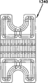
Figure 133 is the skeleton view of Figure 125 wall case lid.
Figure 134 is the skeleton view that is suitable for the cable management dish of Figure 125 wall case.
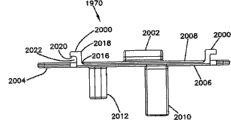
Figure 135-136th, is suitable for the various views of fan-out (fanout) retainer of Figure 125 wall case.
Figure 137 is the view of Figure 144 wall case, demonstration be that exemplary cable moves towards route.
Figure 138 is the base portion of Figure 125 wall case and the decomposition diagram of lid.
Figure 139 is the skeleton view that is suitable for the hinge component of Figure 125 wall case.
Embodiment
What the disclosure related generally to is wall case, and described wall case is constructed to the assembling of the span centre position in the length along optical fiber communication cable easily.Preferably be used in indoor purposes according to the wall case of disclosure principle, such as multitenant unit or ShangWu Building, have multiple subscribers to be located in these places.However, it should be understood that to the wall case according to disclosure principle can be used in indoor or outdoor any need to be in the purposes of the span centre position of communication cable shell convenient for assembly.Specific embodiment can seal, for use in underground (below grade) purposes (for example,, for hand hole (hand holes)).
What Fig. 3-13 showed is the wall case 900 having according to disclosure characteristics of principle.Wall case 900 comprises shell 902, and described shell has base portion 916 and protecgulum 920, and they seal out the inner area of shell 902 jointly.Protecgulum 920 is connected on base portion 916 by hinge 921 pivotables that are positioned in the first side of shell 902.Multiple breech locks 923 are positioned in a side contrary with hinge 921 on shell.Breech lock 923 is constructed to protecgulum 920 to be fixed to the position with respect to base portion 916 closures.Many group fiber adapter 514 are assembled in the end opposite of protecgulum 920.
What Figure 14 drew is one of them fiber adapter 514 isolating from wall case.Fiber adapter 514 comprises main casing 540, has the first member 542 that limits fiber adapter 514 inner port 518 and the second component 544 that limits fiber adapter 514 external port 516.The first and second members 542,544 can be coordinated by pressing (snap-fit) connection interconnection to form main casing 540.Branch joint housing 546 is assemblied in the inside, inside of main casing 540.Spring 548 by branch joint housing 546 outward port 516 setover and allow branch joint housing 546 to float in the inside of main casing 540.As shown in Figure 14, branch joint housing 546 holds standard branch joint 550, and the central axis 552 of described standard branch joint and fiber adapter 514 is co-axially aligned.Branch joint 550 comprises the first end 554 that faces fiber adapter 514 the inners 518 and the second end 556 that faces fiber adapter 514 external port 516.Fiber adapter 514 is assemblied in one of them of the adapter fitting opening that limited by wall case.Fiber adapter 514 is kept nut 560 and remains in adapter fitting opening, and described nut is screwed on the external thread being limited by the first member 542 of main casing 540.In the time that retention nut 560 is screwed to, corresponding adapter fit walls is just trapped between retention nut 560 and the shoulder 564 of main casing 540.Thereby seal member 566 is pressed between main casing 540 and adapter fit walls and provides environmental sealing around adapter fitting opening.
As shown in Figure 15, shown dust cap 568 assemblings have covered the inner port 518 of fiber adapter 514, and shown plug 570 is assembled in the external port 516 of fiber adapter 514.Plug 570 is screwed in the internal thread 572 of external port 516 interior restrictions.Plug 570 also comprises seal member 574 (for example O shape circle), thereby the sealing surfaces 576 in described seal member engagement external port 516 provides environmental sealing between main casing 540 and plug 570.Frenulum 578 is fixed on main casing 540 plug 570 to prevent that plug from misplacing in the time that external port 516 removes.
In the assembling process of wall case, fiber adapter 514 is assembled in through wall case protecgulum and limits in the adapter fitting opening forming.After installing fiber adapter 514, dust cap 568 can be removed so that allowing to end at the joints of optical fibre 530 of optical fiber pigtail (pigtail optical fiber) 528 can be inserted in inner port 518, and described optical fiber pigtail is spliced on the corresponding optical fiber of main push-towing rope line.In the time that internal optical fiber connector 530 is inserted in inner port 518, the cuff of internal optical fiber connector 530 is received in the first end 554 of branch joint 550, and clip 580 works internal optical fiber connector 530 is remained in inner port 518.
When the needs cable of registering one's residence coupled light to one of wall case when upper, the plug 570 of one of fiber adapter 514 is removed from its corresponding external port 516, can be inserted in external port 516 to allow to end at the register one's residence external fiber connector of cable.Demonstrate and be assemblied in the exemplary external joints of optical fibre 582 of registering one's residence on cable 590 ends at Figure 16.External fiber connector 582 comprises housing 584, and retention nut 586 is rotatably assemblied on described housing.Available hand makes retention nut 586 rotate around the central axis 588 of external fiber connector 582.The cable 590 of registering one's residence comprises optical fiber 592, and described optical fiber has the end being assemblied in cuff 594, and described cuff is supported at one end place of housing 584.When external fiber connector 582 is inserted into external port 516 when interior, cuff 594 is received in the second end 556 of branch joint 550.By such mode, it is co-axially aligned with the cuff 594 of external fiber connector 582 that the cuff that makes branch joint 550 grip internal optical fiber connector 530 makes it.By these cuffs are alignd, the corresponding optical fiber 528,592 that makes to be held in cuff is put well by co-axially aligned mode, allows thus light signal to be moved to optical fiber from optical fiber.By retention nut 586 being screwed togather into the mode in internal thread 572, external fiber connector 582 is remained in external port 516.In addition, external fiber connector 582 comprises seal member 596 (for example O shape circle), thereby described seal member engages and seals surface 576 provides environmental sealing between the outside joints of optical fibre 582 and fiber adapter 514.After the end part aligning of optical fiber 528,592, fiber-optic signal just can be propagated easily between optical fiber 528,592.
Referring to Fig. 5, base portion 916 limits the cable in/out opening 932 of two cover groups, for allowing communication cable 933 to connect up through described shell 902.Cable in/out opening 932 cover groups are alignd along the axle 929 that limits cable feedthrough path, and extend through described shell 902 in described path.In the time that cable no longer connects up through opening 932, cable in/out opening 932 can be sealed (seeing Figure 38-44) by plug insertion section 935.Cable break-through insertion section 937 (seeing Figure 31-37) is for sealed open 932 in the time that cable 933 connects up through opening 932.Securing member 939 is for being fixed on insertion section 935,937 on base portion 916.In the time that lid 920 is closed, packing ring (gasket) 940 provides sealing between protecgulum 920 and base portion 916.Packing ring 940 is engaged in the groove 942 extending around base portion 916 open sides girths.Insertion section 935,937 comprises align with passage 942 recessed, depression or groove 943, and they can receive packing ring 940 when packing ring is assemblied in passage 942 when interior.
Still, referring to Fig. 5, dish buttress 949 is assembled in shell 902 inside.Dish buttress 949 comprises deconcentrator dish 950 (seeing Figure 45) and multiple terminal board 952 (seeing Figure 46).One or more deconcentrators 953 can be assembled on deconcentrator dish 950.For example in one embodiment, the deconcentrator of 1 × 16 or two s' 1 × 8 deconcentrator can be assembled on deconcentrator dish 950.While using wall case 900, can stop at the span centre on-position place in shell 902 through the optical fiber 917 of the cable 933 of shell 902 from wiring.The optical fiber 917 stopping can be spliced to and be positioned at the deconcentrator 953 that one of terminal board 952 locates and input on 919.The output optical fibre 957 of deconcentrator 953 can be routed to fan-out 955 positions, and wherein output optical fibre 957 is got up by big envelope (upiacketed) in described position.The output optical fibre 957 good from the big envelope of deconcentrator 953 is preferably connected device, to form the tail optical fiber of connector, described tail optical fiber is plugged in the inner port of fiber adapter 514.Concerning application-specific, the optical fiber of break-through cable 933 can directly access and be spliced on the tail optical fiber of connector in the situation that not using middle deconcentrator.In other embodiments, can be spliced in distribution cable at the optical fiber of the span centre on-position place of break-through cable 933 access, described distribution cable is led to outside wall case 900 through the cable in/out opening 932 not using in addition.
For the ease of access break-through cable 933 and dish 950,952, preferably deconcentrator dish 950 and terminal board 952 are assemblied in shell 902 pivotally.For example, the dish erecting frame 960 (seeing Figure 47-53) that dish 950,952 can be mounted to pivotable above or by it carries, and described dish erecting frame is connected on base portion 916 by hinge means pivotable.Hinge means can comprise pin stand (cradle) 1020 (seeing Figure 25 and 26), and described pin stand is sized to receive pivotally the pivot pin 1022 with pivot disc erecting frame 960 one.Bracket 1021 (seeing Figure 13) is fastened to stand 1020 tops so that within pivot pin 1022 is remained on to stand 1020.Pin stand 1020 is positioned at the office, top of bearing (standoff) 1026, and described bearing makes stand 1020 depart from from the bottom of base portion 916.In this way, pivot disc erecting frame 960 can not interfere with the cable wrap district 1228 that is positioned at base portion 916 bottom places.As shown in figure 13, cable wrap district 1228 comprises the multiple spools 980 that are integrally formed with base portion 916.For the object of storing, the break-through cable 933 not span centre part 1032 of big envelope can be wound onto spool 980 outsides.The span centre part 1232 of big envelope does not typically comprise multiple exposure separator tubes of cable 933.Optical fiber in separator tube can be access in, stops and be spliced in the input 919 of the deconcentrator 953 (seeing Figure 45) on one of deconcentrator dish 952.Termination optical fiber from break-through cable 933 can be by direct splicing to the connector tail optical fiber at terminal board 952 places, maybe can be spliced in the branch-off cables (as the cable of registering one's residence) outside wall case 900.
By pivot disc erecting frame 960, all dishes 950,952 can be pivoted to release position immediately, and break-through cable can be by access (seeing Figure 13) easily in described position.Each in dish 950,952 also preferably can relative to each other move individually pivotly.For example, the dish of bottommost can be connected on frame 960, and now each stacking dish pivotable is subsequently connected on the dish of its below.Joint pin receives body 963 and can be located on frame 960, and is suitable for receiving the correspondence pin of being located on bottommost dish.Such layout contributes to access independent dish to splice or cable management.
Referring to Figure 11-13, what draw is the pivotal arrangements of dish 950,952.What for example, Figure 11 showed is the situation that all dishes are pivoted to off-position.What Figure 12 showed is, and two dishes are pivoted to release position and the 3rd dish is retained in the situation of off-position.What Figure 13 showed is that frame 960 is pivoted to release position, and wherein all dishes have been moved to the position that break-through cable can conveniently be accessed.
Referring now to Figure 101-105,, demonstration be the replacement embodiment that is suitable for the dish erecting frame 1561 of shell 902.Dish erecting frame 1561 comprises first end 1562 and the contrary the second end 1564 arranging.First end 1562 comprises pin parts 1566, and described pin parts are suitable for being received in the pin stand 1020 of base portion 916.
The second end 1564 comprises multiple breech locks springy 1568.In theme embodiment, breech lock 1568 springy is from the top surface 1570 of dish erecting frame 1561 to downward-extension.Each in multiple breech locks springy 1568 comprises the base portion part 1572 engaging with dish erecting frame 1561, and latch portion 1574.Latch portion 1574 comprises lip 1576, and described lip stretches out from latch portion 1574.
Dish erecting frame 1561 further comprises the first terminal board assembly area 1578 being arranged on dish erecting frame 1561 top surfaces 1570.Multiple terminal board erecting frames 1580 are arranged in the first terminal board assembly area 1578, and upwards extend from top surface 1570.In theme embodiment, and only as embodiment, in the first terminal board assembly area 1578, be provided with two terminal board erecting frames 1580.Each in terminal board erecting frame 1580 comprises the base end 1582 engaging with dish erecting frame 1561, and breech lock end 1584.Breech lock end 1584 comprises from the outward extending lip part 1586 of breech lock end 1584.Lip part 1586 is suitable for engaging with terminal board.
In one embodiment, dish erecting frame 1561 comprises the second terminal board assembly area 1587 being arranged on dish erecting frame 1561 basal surfaces 1590.In the embodiment drawing at Figure 126, the deconcentrator dish 1592 that is equipped with deconcentrator is above arranged in the second terminal board assembly area 1587 of basal surface 1590, and terminal board buttress 1800 is arranged in the first terminal board assembly area 1578 of top surface 1570.
Referring now to Figure 106 and 107,, demonstration be the terminal board buttress 1800 that is suitable for coiling erecting frame 1561.In theme embodiment, terminal board buttress 1800 comprises two terminal boards 1802 that are assembled on dish erecting frame 1561.Terminal board 1802 comprises two joint rigging positions 1804.The optical fiber storage area 1806 of storing fiber optic is generally arranged between two joint rigging positions 1804.Optical fiber storage area 1806 comprises two isolated half spools 1808, and unnecessary optical fiber can be wound onto on described spool.Optical fiber storage area also comprises two full spools (full spools) 1810, and it is positioned at by the region limiting between two described half spools 1808.Each in two full spools 1810 comprises grabs card (catch) 1811.Each one of them lip part 1586 of grabbing card 1811 and be suitable for take-up reel erecting frame 1561 terminal board erecting frame 1580 breech lock ends 1584.Optical fiber storage area 1806 further comprises the optical fiber saddle 1812 of arc, and described saddle is arranged in the each inside edge of joint rigging position 1804.Optical fiber storage area 1806 further comprises the central bend radius limiter 1814 between two full spools 1810.
At the U.S. Patent Application Serial Number No.61/039 in March 24 2008 applying date, 045, with April 21 2008 applying date denomination of invention be in " fibre-optical splice dish " (" Fiber Optic Splice Tray ") and the attorney docket U.S. Patent application that is 02316.2786USP1, to have docked cephalic disc buttress 1800 and terminal board 1802 has been done further introduction, the disclosure incorporated of above-mentioned document is incorporated into this.
Referring to returning Fig. 5, insertion section 935,937 is configured to be nested in cable in/out opening 932.Insertion section 935 has the lower part 990 with convex groove, and mate with corresponding concavity groove/identical rail set 1250, and the rail set 1252 being limited at cable in/out opening 932 places by base portion 916.Insertion section 937 has the groove of concavity, with with the rail set 991 of concavity groove cooperation and the rail set 1252 of cable in/out opening 932, while being secured on base portion 916 with convenient insertion section, the big envelope part of break-through cable is put in place with respect to shell 902 clamps.Adhesive tape or other materials can be wound around (for example, around big envelope) around a part of cable 933 of break-through cable in/out opening 932, to better environmental sealing is provided.
Insertion section 935,937 also defines the fastener openings 987 that receives securing member 939.Fastener openings 987 is defined as the outshot 994 by insertion section 935,937.Outshot 994 is outwards given prominence to and is coupled in the corresponding jack or passage 1254 of being located at cable in/out opening 932 places from insertion section 935,937 main bodys, thereby contributes to insertion section to be aligned in opening 932.Insertion section 935,937 main bodys have the taper configuration of mating with the corresponding cone (tapers) of cable in/out opening 932.On the contrary, outshot 994 and respective channel 1254 thereof are not just convergents.
As shown in FIG. 24 and 25, base portion 916 comprises the interior outer end wall 1256,1258 of a few cover groups, and insertion section 935,937 is assemblied between described wall. Wall 1256,1258 defines the recess 1260,1062 aliging with cable in/out opening 932.Insertion section 935,937 comprises inside and outside end teat 1264,1266, and described teat is engaged in the recess 1260,1262 of inside and outside wall 1256,1258. Teat 1264,1266 is generally formed as the shape with recess 1260,1262 shape complementarities.
As shown in Figure 10, base portion 916 is configured to auxiliary, shell 902 is assembled to and be interconnected as the assembling bracket 970 in wall or pillar structure.Assembling bracket has fastener openings 971, and described opening allows bracket 970 to be pre-assembled to as in the structure of wall or pillar.Assembling bracket 970 also comprises a pair of end 972 being engaged in groove 997, and described groove limits and forms by being located at track 973 on shell 902 base portions 916, to shell 902 is fixed on bracket 970.In the use of assembly, bracket 970 is pre-assembled on pillar or wall.Then, shell 902 is located in the top of bracket 970, and its middle slot 997 is alignd with end 972.Then shell is moved downward and makes end 972 in the interior slip of groove 997, between bracket 970 and shell 902, provides connection.Be located at the bottom that the key piece 995 on bracket 970 engages track 973 in the time that shell 902 engages completely with bracket 970.In specific implementations, key piece 995 can be pressed in the opening being limited by shell 902, or otherwise with shell generation pressing coordinate be connected, thereby between bracket 970 and shell 902, provide a kind of more firm connection.
What Figure 17-23 showed is from the isolated lid 920 out of base portion 916.Lid is essentially rectangular, and has open interior to allow tail optical fiber easily to lead to adapter 514.Integral hinge hook 1500 is located in a side of lid 920, and breech lock frame is located on the opposition side of lid.In specific implementations, cable management structure can be located among lid inside as spool.
What Figure 108-114 showed is the replacement embodiment that is suitable for the lid 1620 of shell 902.Lid 1620 comprises front side 1622, the first wall 1624, contrary the second wall 1626 arranging, the first side 1628 and contrary the second side 1630 arranging.The first and second walls 1624,1626 and the first and second sides 1628,1630 are arranged to be generally the structure of rectangle.In theme embodiment, front side 1622 is being generally arc in shape.
In theme embodiment, in the first and second sides 1628,1630, each comprises and is provided with multiple ribs 1640 surface, inside thereon.Multiple ribs 1640 extend to the inside surface 1636 of front side 1622 from opening 1634.It is that the first and second walls 1624,1626 and the first and second sides 1628,1630 provide intensity that multiple ribs 1640 are suitable for.
In the first and second walls 1624,1626, each defines the multiple adapters openings 1642 that extend in lid 1620 inside 1632.Multiple first ribs 1644 are arranged on the surface, inside of the first and second walls 1624,1626.In theme embodiment, multiple first ribs 1644 are arranged between adjacent adapters openings 1642 in longitudinal.
Multiple second ribs 1646 are arranged on the outer surface of the first and second walls 1624,1626.In theme embodiment, multiple second ribs 1646 comprise multiple longitudinal ribs 1648 and latitude direction rib 1650.Longitudinal rib 1648 and latitude direction rib 1650 are arranged between adjacent adapters openings 1642.It is that the inside and outside surface of the first and second walls 1624,1626 provides intensity that multiple the first and second ribs 1646 are suitable for.
What Figure 24-30 showed is from the isolated base portion 916 out of protecgulum 920.Base portion comprises integral hinge pin 1502, and pelican hook 1500 hooks of lid 920 are on described joint pin.Base portion 916 be essentially rectangular and limit open inside, optical fiber can easily wiring and management in described open interior.As implied above, cable management spool 980 is one-body molded with base portion.In use, unnecessary optical fiber or cable can be looped around around the spool for cable management and/or storage.Joint pin is located in a side of base portion, and breech lock is grabbed card and is located on the opposition side of base portion.
What Figure 115-121 showed is the replacement embodiment that is suitable for the base portion 1716 of shell 902.Base portion 1716 comprises base wall 1718, the first wall 1720, contrary the second wall 1722 arranging, the first side 1724 and contrary the second side 1726 arranging.Base wall 1718, the first and second walls 1720,1722 and the first and second sides 1724,1726 limit internal chamber 1728 jointly.The first and second walls 1720,1722 define multiple cable openings 1730, and cable enters and leave shell 902 through described opening.
The surface, inside of base portion 1,716 second sides 1726 can comprise pin stand 1020 (the best illustrates in Figure 116), and described pin stand is suitable for receiving pivotally the pivot pin 1022 with pivot disc erecting frame 960 one.Pin stand 1020 is located at the office, top of bearing 1026, and described bearing departs from pin stand 1020 and the bottom of base portion 1716.
Multiple integral hinge pins 1502 are arranged on the outer surface of base portion 1,716 second sides 1726.Integral hinge pin 1502 is suitable for receiving the pelican hook 1500 of lid 1620.In one embodiment, multiple integral hinge pins 1502 extend substantially in the whole length of the second side 1726.In another embodiment, be provided with five integral hinge pins 1502 along the second side 1726.In another embodiment, be provided with eight integral hinge pins 1502 along the second side 1726.
The first side 1724 of base portion 1716 can comprise breech lock jack 1740.In one embodiment, breech lock jack 1740 is suitable for the breech lock springy 1568 of take-up reel erecting frame 1561.Breech lock jack 1740 comprises the latch openings 1742 arranging along length.Latch openings 1742 is suitable for the lip 1576 of the latch portion 1574 of take-up reel erecting frame 1561 breech lock 1568 springy.
What Figure 54-56 showed is from the isolated dish buttress 949 out of shell 902.Usually, dish buttress 949 comprises the position hinge side contrary with breech lock side 1,072 1070.As shown in Figure 54, the each dish in dish buttress 949 comprises two double-pin parts 1074 that are assemblied in hinge side 1070 places.As shown in Figure 57-61, double-pin part 1074 has pressing and is engaged in the assembling post 1076 in corresponding opening in dish, thereby double-pin part 1074 is assembled on described dish.Each in double-pin part 1074 also comprises two joint pins 1078.The dish of dish buttress 949 is to be connected to over each otherly by being pivoted bar 1080 (seeing Figure 54 and Figure 62-66) pivotable, and the wherein said each pressing with contrary placement of bar that is pivoted coordinates jack 1082.As shown in Figure 54, the pressing that is pivoted bar 1080 coordinates jack 1082 to be pressed on the joint pin 1078 of adjacent disc, thereby provides and be pivoted between adjacent disc.For the dish of bottommost, two in joint pin 1078 are pressed in the joint pin receiver 963 of pivot disc erecting frame 960.Securing member also can be used to be fixed to pivotally on dish erecting frame 960 non-nethermost dish.
Referring to Figure 55, the breech lock side 1072 of dish buttress 949 comprises two the double-pin parts 1074 that are fixed on bottommost dish and is fixed in other dishes two latch components 1084 on each.As shown in Figure 72-76, in breech lock part 1084, each comprises assembling post 1086, thereby wherein said assembling post is pressed and is engaged in by the corresponding opening that limits of dish, breech lock part 1084 being fixed on dish.In breech lock part 1084, each also comprises breech lock folder 1088 and latch pin 1090.In the time being pivoted to off-position to price fixing, breech lock folder 1088 is coupled to and is located on the corresponding latch pin 1090 of dividing on dish with regard to pressing, to described dish in the closed position is latchable to and is divided on dish.By described dish being pulled away to the mode of dividing into dish, making breech lock folder 1088 depart from engagement from latch pin 1090, and then allow described dish to be moved to release position.Two pressings in the pin 1078 of bottommost dish refer to that pressing on 1094 (seeing Figure 67-71) coordinates in jack 1092 being located at cable management, and described cable management refers to append on base portion 916.Refer to 1094 mode by bottommost dish is upwards pulled away to cable management, allow bottommost dish to be pivoted to release position thereby pin 1078 can coordinate jack 1092 to depart from engagement from pressing, the inner area of base portion 916 can be accessed more completely on described position.
Referring to Figure 67-71, cable management refers to that 1094 is roughly L shaped, and comprises the leg 1098 of vertical leg 1096 and level.Vertically leg 1096 comprises pressing component 1100.Vertically leg 1096 is for example fixed on, in the corresponding jack 1102 of being located in base portion 916 (, connecting by pressing).Assembling like this, the function of horizontal leg 1098 be the auxiliary Optical Fiber Winding that keeps around the cable wrap district 1228 at base portion 916 bottom places so that optical fiber not can and Pan Duo occur disturb or move between base portion 916 and lid 920.
The york piece of other types can be used to the cable of compatible other types.What for example, Figure 81 showed is can be by wiring the cut-open view through the exemplary cable 1330 of registering one's residence of one of cable in/out opening 932.The cable 1330 of registering one's residence comprises the central buffer tube 1332 that contains one or more optical fiber.The cable 1330 of registering one's residence also comprises the strength member 1334 that is positioned on separator tube 1330 opposition sides and the big envelope 1336 of coverage strength parts 1334 and central buffer tube 1332.What Figure 55 showed is two york pieces 1338 that are mechanically fixed on shell that are configured to register one's residence in cable 1330.York piece 1338 has multi-piece type structure, comprises middle parts 1340 and two end pieces 1342.Middle parts 1340 (shown in Figure 83-89) comprise upper and lower surface, define the clamp jack 1344 that is suitable for receiving the cable 1330 of registering one's residence.Clamp jack 1344 is also limited in end pieces 1342 surfaces (seeing Figure 90-96) of middle parts 1340.Clamp jack 1344 defines path 1345 jointly, and described path has the middle region 1346 of amplification and narrower outside area 1348.When the cable 1330 of registering one's residence is fixed on york piece 1338 when interior, thereby narrower outside area 1348 clamps are through registering one's residence cable big envelope prop up strength member 1334 cable 1330 of registering one's residence and be mechanically fixed on york piece 1338.The central area 1346 amplifying prevented from the registering one's residence central buffer tube 1332 of cable 1330 is crushed in clamp process.Together with the middle parts 1340 of york piece 1338 are tightened to by use securing member with end pieces 1342, described securing member extends through the securing member receiver 1350 that is defined through york piece 1338.In use, york piece 1338 fits together with the cable 1330 of registering one's residence that york piece path is crossed in break-through.Securing member is inserted through subsequently fastener openings and is screwed in the boss 1328 (seeing Figure 24 and 25) of being located at base portion 916 bottom places.When securing member is clasped, the member 1340 of york piece 1338, thus 1342 be tightened to together stably pincers and clamp the cable 1330 of registering one's residence.In specific embodiment, gusset plate 1352 can be located at top side and the bottom side of york piece 1338,1320, as shown in Figure 55.In addition, if the further mechanical maintenance effect of needs can be used extra securing member, so as extra strength member fixture 1354 (seeing Figure 55) is fixed to the strength member of cable on shell 902.
Extraly, in order to promote the cable management effect in shell 902, extra cable management refers to that 1560 (seeing Figure 77-81) can be fixed on the various positions in base portion 916.Coordinate jack except not being located at pressing on horizontal leg, cable management refers to that 1560 have with cable management and refer to 1094 identical structures.As shown in figure 13, demonstration be that multiple cable managements refer to that 1560 are pressed among the jack of being located in cable management spool 980, described spool and base portion 916 are one-body molded.
Referring now to Figure 122-124,, demonstration be that cable management refers to 1820 replacement embodiment.Cable management refers to that 1820 is roughly L shaped, and comprises the leg 1824 of vertical leg 1822 and level.Vertical leg 1820 comprises first surface 1826 and the contrary second surface 1828 arranging.Pressing component 1830 is arranged on second surface 1828, and is suitable for the complementary pressing component engagement in corresponding jack 1102, and wherein said jack is arranged on around the cable wrap district 1228 being located in base portion 916.
Vertically the first surface 1826 of leg 1822 comprises outward extending thrust 1832 from first surface 1826.In theme embodiment, thrust 1832 is in abutting connection with the first surface of corresponding jack 1102, instant keep second of first surface 1826 and corresponding jack adjacent, described second arrange contrary with first surface, thus assist the engagement of pressing component 1830 and complementary pressing component.
For cable management being referred to 1820 are installed in corresponding jack 1102, vertically leg 1822 is just inserted in the corresponding jack 1102 in cable wrap district 1228 and is advanced in described jack 1102.Vertically leg 1822 just stops insertion until pressing component 1830 engages with the complementary pressing component in jack 1102.
For cable management being referred to 1820 remove from corresponding jack 1102, the end 1832 of horizontal leg 1824 will be pushed to base portion 916.In the time that horizontal leg 1824 is pushed to base portion 916, the pressing component 1830 of second surface 1828 departs from and engages with complementary pressing component.Because pressing component 1830 departs from and engages with complementary pressing component, by pulling vertical leg 1822 cable management can be referred to 1820 remove from corresponding jack 1102.
What Figure 97 and 98 showed is the extra enclosure and lid, and it can be mounted to provides the protection of enhancing and restriction to be connected to aerial lug on shell 902.What Figure 99 and 100 showed is a kind of version of replacing, and wherein end cap is fixed to the part of having sealed the joints of optical fibre on shell 902 otherwise can come out.
Referring now to Figure 125 and 126,, demonstration be wall case 1900 one replace embodiment.In the embodiment of theme, wall case 1900 is shells 1901 of rectangle, has base portion 1902 and lid 1904.
Referring now to Figure 138 and 139,, hinge component, generally refers to 1504, and base portion 1902 is engaged on lid 1904 pivotally.Hinge component 1504 comprises pin parts 1506 and hinge fraction 1508.In theme embodiment, hinge component 1504 comprises multiple pin parts 1506 and multiple hinge fraction 1508.In one embodiment, pin parts 1506 are arranged on base portion 1902 wherein in a side, and this side along base portion 1902 is extended in longitudinal, and hinge fraction 1508 is arranged on lid 1904 wherein in a side.
Each in hinge fraction 1508 comprises base end 1512 and the free end 1514 being oppositely arranged.In theme embodiment, the base end 1512 of hinge fraction 1508 is assembled (for example, be fixedly mounted with, connection, fastening, molded etc.) on a wherein side of lid 1904.
What will introduce now is that pin parts 1506 insert the situation in the hinge fraction 1508 of hinge component 1504.In the time that pin parts 1506 align with opening 1518 in the vertical directions of hook portion 1516, pin parts 1506 are just inserted in opening 1518.Along with the insertion of pin parts 1506, pin parts 1506 come in contact with the outside surface 1528 of holding member 1520.Along with pin parts 1506 are pushed in opening 1518, holding member 1520 is towards deflection in this side direction of lid 1904 to deflected position (flexed position).Along with pin parts 1506 are engaged in opening 1518, holding member 1520 rebounds (snap back) to slack position, thereby the second end 1526 of holding member 1520 can be blocked at least a portion of opening 1518, and pin parts 1506 are remained in opening 1518.In theme embodiment, one of end face 1530 abutment pin parts 1506 of the second end 1526 are to remain on pin parts 1506 in opening 1518.
In order to make hinge component 1504 depart from engagement, holding member 1520 can be by manually towards this side deflection of lid 1904.Along with holding member 1520 by manually towards lid 1904 deflections, pin parts 1506 just can from opening 1518, remove.
Refer again to Figure 125 and 126, base portion 1902 defines and allows communication cable 933 to connect up through two cover group cable openings 1906 of shell 1901.Cable opening 1906 cover groups are alignd along limiting the axle 1908 that extends through shell 1901 feedthrough path.
Referring now to Figure 125-128,, in one embodiment, branch-off cables is left shell 1901 through cable opening 1906.Branch-off cables is to have at least one optical fiber to be spliced to the Connectorized fiber optic cabling on communication cable 933 optical fiber at terminal board 1802 places.Branch-off cables is led to subscriber position or transfer on-position from shell 1901.For they being sealed in the time that these branch-off cables are left shell, branch-off cables is connected up through retaining ring 1910, and described retaining ring is arranged in cable in/out opening 1906.
Each retaining ring 1910 comprises the main body 1912 with outside surface 1914, and described main part limitation goes out at least one cable perforation 1916, and branch-off cables connects up through described perforation.In theme embodiment, only, in the mode of embodiment, main body 1912 defines two cable perforation 1916.In another embodiment, only, in the mode of embodiment, main body 1912 defines a cable perforation 1916.
The outside surface 1914 of main body 1912 comprises from the outward extending multiple fins of outside surface 1914 (fins) 1918.In theme embodiment, multiple fins 1918 are generally parallel to the end surfaces 1920 of retaining ring 1910 and extend around a part for outside surface circumference.Multiple fins 1918 of retaining ring 1910 are suitable for being received by the passage in base portion 1902 or groove 1921.The facilities of fin 1918 in passage 1921 prevented that retaining ring 1910 from axial displacement occurring in cable opening 1906, also makes the earial drainage path of fluid increase to some extent.
Referring now to Figure 126 and 129,, base portion 1902 comprises the cable clamp region 1922 with the 1906 adjacent settings of cable opening.Each cable clamp region 1922 comprises and is suitable for receiving recessed 1924 of securing member 1926 (shown in Figure 130 and 131).In theme embodiment, recessed 1924 comprise the Part I 1928 and the Part II 1930 that are generally cylindrical shape.In theme embodiment, Part II 1930 comprises the side of not waiting from Part II 1930 centre distances.
Referring now to Figure 126,, 130 and 131, demonstration be securing member 1926.Securing member 1926 comprises the first axial end portion 1932 and the second axial end portion 1934.The first axial end portion 1932 comprises the first retaining part 1936 and the second retaining part 1938.
The first retaining part 1936 is generally cylindrical shape, and size is set as making overall diameter to be slightly larger than the interior diameter of recessed 1924 Part I 1928.In theme embodiment, the outside surface of the first retaining part 1936 is textured (texturized) (as embossing (knurled) etc.).The overall diameter that the first retaining part 1936 outside surfaces are bigger and texturing structure have been assisted securing member 1926 have axially been remained in recessed 1924.
In the embodiment of theme, the second retaining part 1938 comprises the side with the multiple points that do not wait from recessed 1928 centre distances.By having several sides not equidistant with recessed 1924 centers, the second retaining part 1938 just can prevent that securing member 1926 from rotating around recessed 1924 center when mounted.
In the embodiment of theme, the second axial end portion 1934 is suitable for engaging with the open-work (thru-hole) of Cable forceps clamp assembly.A plurality of screw threads that are arranged on the second axial end portion 1934 are suitable for engaging with nut Cable forceps clamp assembly being fixed on base portion 1902 via securing member 1926, and communication cable 933 is fixing or clamp is in cable opening 1906 thus.
Referring now to Figure 126 and 129,, in cable clamp region 1922, each comprises end wall 1950.End wall 1950 comprises opening, opening described in the impact damper break-through of terminal cable 933.In one embodiment, the overall diameter of described aperture efficiency communication cable 933 big envelopes is little.The overall diameter of aperture efficiency communication cable 933 big envelopes that have due to end wall 1950 is little, therefore can prevent that communication cable 933 from axial displacement occurring or be pushed to cross end wall 1950 and enter in shell 1901.
In cable clamp region 1922, each further comprises multiple supporting walls 1952.Supporting walls 1952 is avoided or has been reduced communication cable 933 in the inner mobile risk of side direction (side is to side) that occurs of shell 1901.In theme embodiment, in supporting walls 1952, each stretches out from cable clamp region 1922 in general parallel with end wall 1950 direction.In theme embodiment, supporting walls 1952 usually aligns with recessed 1924.
Referring now to Figure 101-105 and 123,, base portion 1902 further comprises and being suitable for and multiple 1954 that are arranged on the pin parts 1566 of dish on erecting frame 1561 and engage.Because the pin parts 1566 of dish erecting frame 1561 are arranged in the frame 1954 of base portion 1902, dish erecting frame 1561 just can be around the axis of pin parts 1,566 1956 pivotable between release position (shown in Figure 126) and off-position (shown in Figure 132).
In frame 1954, each comprises groove 1958 (the best illustrates in Figure 126).Because dish erecting frame 1561 is in release position, pin parts 1566 can be advanced in groove 1958, until the end of pin parts 1566 adjacent channels 1958.Along with the end of pin parts 1566 adjacent channels 1958, the marginal portion 1959 of dish erecting frame 1561 is arranged in groove 1958, just can not be pivoted around the axis of pin parts 1,566 1956 thereby make to coil erecting frame 1561.
In one embodiment, there is terminal board buttress 1800 to be arranged on the dish erecting frame 1561 being arranged on dish erecting frame basal surface 1590 with deconcentrator dish 1592 on top surface 1570 axis around pin parts 1,566 1956 is pivoted to release position.At release position place, deconcentrator dish 1592 can be accessed by.In order to prevent that coiling erecting frame 1561 is pivoted to off-position because of carelessness, the pin parts 1566 of dish erecting frame 1561 are pushed in the groove 1958 until end of pin parts 1566 adjacent channels 1958.After access deconcentrator dish 1592, can be by pulling in one direction the mode of dish erecting frame 1561, make pin parts 1566 no longer with the end abutment of groove 1958, and marginal portion 1959 is also no longer arranged in groove 1958, makes to coil erecting frame 1561 and can be pivoted to off-position.Because the marginal portion 1959 of dish erecting frame 1561 is no longer arranged in groove 1958, dish erecting frame 1561 just can be pivoted in off-position.In this off-position, the each terminal board 1802 in terminal board buttress 1800 can be access in.
Referring now to Figure 126,, 132 and 133, lid 1904 comprises base wall 1960, described base wall has the cable management assembly area 1962 that is suitable for receiving cable management dish 1964, also comprise multiple sidewalls 1966, described sidewall has the fan-out assembly area 1968 that is suitable for receiving fan-out retainer 1970 (Figure 135, shown in 136).
The cable management assembly area 1962 of base wall 1960 comprises multiple pilot holes 1972.Pilot hole 1972 is suitable for receiving the securing member 1974 arranging through the hole 1976 in cable management dish 1964.In theme embodiment, cable management assembly area 1962 is arranged on multiple ridges 1978 that base wall 1960 is provided support.
Referring now to Figure 132 and 134,, demonstration be cable management dish 1964.Cable management dish 1964 comprises core 1980 and multiple end 1982.In theme embodiment, core 1980 comprises that shape is generally semicircular end, and end 1982 is generally crescent or half moon (quarter-moon) shape.Core 1980 and end 1982 define the first fiber optic loop 1984 and the second fiber optic loop 1986 jointly.In theme embodiment, the first fiber optic loop 1984 is arranged on the inside of the second fiber optic loop 1986.Multiple maintenances refer to that 1988 partly extend across the top of the first and second fiber optic loop 1984,1986.As shown in the best in Figure 132, optical fiber 1990 arrives through the first and/or second fiber optic loop 1984,1986 wirings of cable management dish 1964 connector 1994 being arranged in cap side-wall 1966 from the fan-out portion 1992 being arranged on fan-out retainer 1970.
Referring now to Figure 132 and 133,, the fan-out region 1968 on sidewall 1966 comprises multiple maintenance ribs 1996 and at least one latch openings 1998.Keep rib 1996 be suitable for the sliding mode of engagement to receive the maintenance breech lock 2000 on fan-out retainer 1970, and the engagement system that latch openings 1998 is suitable for coordinating with pressing receive the elastic force breech lock 2002 on fan-out retainer 1970.
Referring now to Figure 135 and 136,, demonstration be fan-out retainer 1970.In theme embodiment, fan-out retainer 1970 is suitable for receiving multiple fan-out portion.In one embodiment, and only as embodiment, fan-out retainer 1970 is suitable for receiving at least two fan-out portions.In another embodiment, and only as embodiment, fan-out retainer 1970 is suitable for receiving four fan-out portions.
Fan-out retainer 1970 comprises base portion 2004, and described base portion has front surface 2006 and the contrary rear surface 2008 arranging.Fan-out retainer 1970 is suitable for keeping multiple fan-out portion.In theme embodiment, multiple holding members 2010 and multiple steady arm 2012 remain to multiple fan-out portion on fan-out retainer 1970.
In theme embodiment, multiple steady arms 2012 extend from the front surface 2006 of fan-out retainer 1970.In theme embodiment, and only as embodiment, there are two steady arms 2012.Steady arm 2012 is suitable for engaging with the jack in fan-out portion.
What extend out from rear surface 2008 is multiple maintenance breech locks 2000 and elastic force breech lock 2002.Keep breech lock 2000 to comprise the base end 2016 and the free end 2018 that are additional on rear surface 2008.Free end 2018 comprises lip 2020 and limits the passage 2022 between lip 2020 and the rear surface 2008 of fan-out retainer 1970.Each passage 2022 is suitable for one of the maintenance rib 1996 in engage lids 1904 fan-out regions 1968.In theme embodiment, the engagement between passage 2022 and maintenance rib 1996 is the engagement of sliding.
Elastic force breech lock 2002 comprises base portion part 2024 and free part 2026.Free part 2026 comprises the lip 2028 that is suitable for engaging latch openings 1998.Owing to keeping rib 1996 to be engaged in the passage 2022 of fan-out retainer 1970, fan-out retainer 1970 is pushed to the base wall 1960 of lid 1904.Fan-out retainer 1970 is pulled to until the free part 2026 of elastic force breech lock 2002 engages with latch openings 1998.
Referring now to Figure 137,, what will introduce is exemplary cable schematic circuit diagram.Communication cable 933 enters shell 1901 through the cable opening 1906 in base portion 1902.The optical fiber of communication cable 933 leads on the terminal board 1802 of dish buttress 1800.In terminal board 1802, optical fiber is connected on the input optical fibre of deconcentrator by light.Input optical fibre leads on dish erecting frame 1561 basal surfaces 1590, to the deconcentrator being assemblied on deconcentrator dish 1592.
Output optical fibre leads to from deconcentrator the fan-out portion being assemblied on fan-out retainer 1970.In one embodiment, output optical fibre is arranged in ribbon-style cable, and described ribbon-style cable is arranged in bifurcated pipe.What big envelope got up has the independent optical fiber of connector end subsequently from fan-out portion towards being arranged in the inner port of the fiber adapter 514 on lid 1904, and is plugged in these inner port.In theme embodiment, the unnecessary optical fiber between fan-out portion and fiber adapter 514 inner port is around the first and/or second ring 1984,1986 wirings of cable management dish 1964.
Illustrating above provides the embodiment how particular aspects input being put into practice.Should be understood that these aspects can be without departing from the spirit and scope in the present disclosure, by other be different from herein concrete shown in and those modes of introducing drop into practice.
Claims (8)
1. a wall case, comprising:
Shell, described shell has
Base portion;
Be connected to the protecgulum on described base portion, wherein, described base portion and described protecgulum seal out the inner area of described shell jointly;
Be assemblied in the multiple fiber adapter on described shell, wherein, described fiber adapter comprises the inner port that is arranged in described inner area and the external port that is positioned at described outer surface of outer cover place;
The Pan Duo that is assemblied in the inside, described inner area of described shell, described Pan Duo comprises:
Pivotable is connected to the dish erecting frame on described shell, and described dish erecting frame comprises: top surface and the contrary basal surface arranging, wherein, the first terminal board assembly area is set on described top surface, and the second terminal board assembly area is set on described basal surface;
Be arranged on the multiple dishes in described the first terminal board assembly area, the each dish being arranged in the multiple dishes in described the first terminal board assembly area also relative to each other moves individually pivotly; With
Be arranged on the dish in described the second terminal board assembly area.
2. wall case claimed in claim 1, wherein, described dish erecting frame is connected on the protecgulum of described shell by pivotable.
3. wall case claimed in claim 1, wherein, each being arranged in the described multiple dishes in described the first terminal board assembly area is terminal board.
4. wall case claimed in claim 3, wherein, described in each, terminal board comprises two joint rigging positions.
5. wall case claimed in claim 4 wherein, arranges optical fiber storage area between described two joint rigging positions.
6. wall case claimed in claim 5, wherein, described optical fiber storage area comprises two isolated half spools, unnecessary optical fiber can be reeled around described half spool.
7. wall case claimed in claim 6, wherein, described optical fiber storage area comprises two full spools, described full spool is in the region being limited between described two and half spools.
8. wall case claimed in claim 1, wherein, the described dish being arranged in described the second terminal board assembly area is deconcentrator dish, it has the deconcentrator being fitted thereon.
Applications Claiming Priority (11)
| Application Number | Priority Date | Filing Date | Title |
|---|---|---|---|
| US2010008P | 2008-01-09 | 2008-01-09 | |
| US61/020,100 | 2008-01-09 | ||
| US2921408P | 2008-02-15 | 2008-02-15 | |
| US61/029,214 | 2008-02-15 | ||
| US3904908P | 2008-03-24 | 2008-03-24 | |
| US61/039,049 | 2008-03-24 | ||
| US4665608P | 2008-04-21 | 2008-04-21 | |
| US61/046,656 | 2008-04-21 | ||
| US7735008P | 2008-07-01 | 2008-07-01 | |
| US61/077,350 | 2008-07-01 | ||
| PCT/US2009/030414 WO2009089327A2 (en) | 2008-01-09 | 2009-01-08 | Wall box adapted to be mounted at a mid-span access location of a telecommunications cable |
Publications (2)
| Publication Number | Publication Date |
|---|---|
| CN101965531A CN101965531A (en) | 2011-02-02 |
| CN101965531B true CN101965531B (en) | 2014-06-04 |
Family
ID=40467319
Family Applications (1)
| Application Number | Title | Priority Date | Filing Date |
|---|---|---|---|
| CN200980108160.5A Expired - Fee Related CN101965531B (en) | 2008-01-09 | 2009-01-08 | Wall box adapted to be mounted at a mid-span access location of a telecommunications cable |
Country Status (6)
| Country | Link |
|---|---|
| US (7) | US8111966B2 (en) |
| EP (1) | EP2238493A2 (en) |
| CN (1) | CN101965531B (en) |
| AU (1) | AU2009204170A1 (en) |
| BR (1) | BRPI0906796A2 (en) |
| WO (1) | WO2009089327A2 (en) |
Families Citing this family (162)
| Publication number | Priority date | Publication date | Assignee | Title |
|---|---|---|---|---|
| US7722558B2 (en) | 2005-02-15 | 2010-05-25 | Ott Douglas E | Trocar sleeve for jet stream condition |
| US8798427B2 (en) | 2007-09-05 | 2014-08-05 | Corning Cable Systems Llc | Fiber optic terminal assembly |
| WO2009089327A2 (en) | 2008-01-09 | 2009-07-16 | Adc Telecommunications, Inc. | Wall box adapted to be mounted at a mid-span access location of a telecommunications cable |
| CN101521545B (en) * | 2008-02-27 | 2012-10-10 | 3M创新有限公司 | High-density optical fiber distributing hub |
| US8718434B2 (en) | 2008-07-01 | 2014-05-06 | Adc Telecommunications, Inc. | Cable enclosure with sealed cable entry port |
| US8452148B2 (en) | 2008-08-29 | 2013-05-28 | Corning Cable Systems Llc | Independently translatable modules and fiber optic equipment trays in fiber optic equipment |
| US11294135B2 (en) | 2008-08-29 | 2022-04-05 | Corning Optical Communications LLC | High density and bandwidth fiber optic apparatuses and related equipment and methods |
| CN102209921B (en) * | 2008-10-09 | 2015-11-25 | 康宁光缆系统有限公司 | There is the fibre-optic terminus supported from the adapter panel of the input and output optical fiber of optical splitters |
| ES2791702T3 (en) | 2008-10-10 | 2020-11-05 | Surgiquest Incorporated | System to improve gas recirculation in pneumatic sealed surgical trocars |
| US8879882B2 (en) | 2008-10-27 | 2014-11-04 | Corning Cable Systems Llc | Variably configurable and modular local convergence point |
| US9036975B2 (en) | 2009-02-24 | 2015-05-19 | Adc Telecommunications, Inc. | Fiber optic cable pass-thru fitting |
| ATE534049T1 (en) | 2009-02-24 | 2011-12-15 | Ccs Technology Inc | CABLE HOLDING DEVICE OR ARRANGEMENT FOR USE WITH A CABLE |
| US9116310B2 (en) | 2009-03-06 | 2015-08-25 | Adc Telecommunications, Inc. | Fiber optic cable pass-thru fitting with a cable retention member for routing strength members |
| WO2010117656A2 (en) * | 2009-04-06 | 2010-10-14 | Adc Telecommunications, Inc. | Drop cable pass-thru fitting |
| US8699838B2 (en) | 2009-05-14 | 2014-04-15 | Ccs Technology, Inc. | Fiber optic furcation module |
| US8280216B2 (en) | 2009-05-21 | 2012-10-02 | Corning Cable Systems Llc | Fiber optic equipment supporting moveable fiber optic equipment tray(s) and module(s), and related equipment and methods |
| US9075216B2 (en) | 2009-05-21 | 2015-07-07 | Corning Cable Systems Llc | Fiber optic housings configured to accommodate fiber optic modules/cassettes and fiber optic panels, and related components and methods |
| US8712206B2 (en) | 2009-06-19 | 2014-04-29 | Corning Cable Systems Llc | High-density fiber optic modules and module housings and related equipment |
| AU2010263057A1 (en) | 2009-06-19 | 2012-02-02 | Corning Cable Systems Llc | High density and bandwidth fiber optic apparatuses and related equipment and methods |
| US8929706B2 (en) * | 2009-08-31 | 2015-01-06 | Cisco Technology, Inc. | Fiber optic cable storage enclosure |
| US8180191B2 (en) * | 2009-10-23 | 2012-05-15 | Corning Cable Systems Llc | Mounting platforms for integrally supporting an optical splice tray(s) and/or an optical splitter(s) in a multi-port optical connection terminal and related methods |
| US8625950B2 (en) | 2009-12-18 | 2014-01-07 | Corning Cable Systems Llc | Rotary locking apparatus for fiber optic equipment trays and related methods |
| AU2009357257B2 (en) * | 2009-12-23 | 2015-08-20 | Prysmian S.P.A. | Optical termination assembly |
| US8593828B2 (en) | 2010-02-04 | 2013-11-26 | Corning Cable Systems Llc | Communications equipment housings, assemblies, and related alignment features and methods |
| DE102010010428B4 (en) * | 2010-03-05 | 2012-07-19 | Adc Gmbh | Connection box for fiber optic cable |
| US9547144B2 (en) | 2010-03-16 | 2017-01-17 | Corning Optical Communications LLC | Fiber optic distribution network for multiple dwelling units |
| US8913866B2 (en) | 2010-03-26 | 2014-12-16 | Corning Cable Systems Llc | Movable adapter panel |
| US8792767B2 (en) * | 2010-04-16 | 2014-07-29 | Ccs Technology, Inc. | Distribution device |
| AU2011265751B2 (en) | 2010-04-16 | 2015-09-10 | Corning Optical Communications LLC | Sealing and strain relief device for data cables |
| EP2381284B1 (en) | 2010-04-23 | 2014-12-31 | CCS Technology Inc. | Under floor fiber optic distribution device |
| US8660397B2 (en) | 2010-04-30 | 2014-02-25 | Corning Cable Systems Llc | Multi-layer module |
| US8705926B2 (en) | 2010-04-30 | 2014-04-22 | Corning Optical Communications LLC | Fiber optic housings having a removable top, and related components and methods |
| US9632270B2 (en) | 2010-04-30 | 2017-04-25 | Corning Optical Communications LLC | Fiber optic housings configured for tool-less assembly, and related components and methods |
| US20110268408A1 (en) * | 2010-04-30 | 2011-11-03 | Giraud William J | Door fiber management for fiber optic housings, and related components and methods |
| US8879881B2 (en) | 2010-04-30 | 2014-11-04 | Corning Cable Systems Llc | Rotatable routing guide and assembly |
| US9720195B2 (en) | 2010-04-30 | 2017-08-01 | Corning Optical Communications LLC | Apparatuses and related components and methods for attachment and release of fiber optic housings to and from an equipment rack |
| US9075217B2 (en) | 2010-04-30 | 2015-07-07 | Corning Cable Systems Llc | Apparatuses and related components and methods for expanding capacity of fiber optic housings |
| US9519118B2 (en) | 2010-04-30 | 2016-12-13 | Corning Optical Communications LLC | Removable fiber management sections for fiber optic housings, and related components and methods |
| US11251608B2 (en) | 2010-07-13 | 2022-02-15 | Raycap S.A. | Overvoltage protection system for wireless communication systems |
| US8718436B2 (en) | 2010-08-30 | 2014-05-06 | Corning Cable Systems Llc | Methods, apparatuses for providing secure fiber optic connections |
| US9547145B2 (en) | 2010-10-19 | 2017-01-17 | Corning Optical Communications LLC | Local convergence point for multiple dwelling unit fiber optic distribution network |
| US9279951B2 (en) | 2010-10-27 | 2016-03-08 | Corning Cable Systems Llc | Fiber optic module for limited space applications having a partially sealed module sub-assembly |
| EP2633354A1 (en) | 2010-10-28 | 2013-09-04 | Corning Cable Systems LLC | Impact resistant fiber optic enclosures and related methods |
| US8662760B2 (en) | 2010-10-29 | 2014-03-04 | Corning Cable Systems Llc | Fiber optic connector employing optical fiber guide member |
| US9116324B2 (en) | 2010-10-29 | 2015-08-25 | Corning Cable Systems Llc | Stacked fiber optic modules and fiber optic equipment configured to support stacked fiber optic modules |
| US8494332B2 (en) | 2010-11-15 | 2013-07-23 | Adc Telecommunications, Inc. | Tray assembly for a fiber optic enclosure |
| CA2819235C (en) | 2010-11-30 | 2018-01-16 | Corning Cable Systems Llc | Fiber device holder and strain relief device |
| GB201101749D0 (en) * | 2011-02-01 | 2011-03-16 | Hellermanntyton Data Ltd | Storage assembly for fibre-optic cables |
| EP2671107A1 (en) | 2011-02-02 | 2013-12-11 | Corning Cable Systems LLC | Dense shuttered fiber optic connectors and assemblies suitable for establishing optical connections for optical backplanes in equipment racks |
| KR101253889B1 (en) * | 2011-03-10 | 2013-04-16 | 이건테크놀로지 주식회사 | Terminal box for optical cable |
| US9008485B2 (en) | 2011-05-09 | 2015-04-14 | Corning Cable Systems Llc | Attachment mechanisms employed to attach a rear housing section to a fiber optic housing, and related assemblies and methods |
| CN103649805B (en) | 2011-06-30 | 2017-03-15 | 康宁光电通信有限责任公司 | Fiber plant assembly of shell using non-U-width size and associated method |
| US8953924B2 (en) | 2011-09-02 | 2015-02-10 | Corning Cable Systems Llc | Removable strain relief brackets for securing fiber optic cables and/or optical fibers to fiber optic equipment, and related assemblies and methods |
| US9069151B2 (en) | 2011-10-26 | 2015-06-30 | Corning Cable Systems Llc | Composite cable breakout assembly |
| US9038832B2 (en) | 2011-11-30 | 2015-05-26 | Corning Cable Systems Llc | Adapter panel support assembly |
| US9219546B2 (en) | 2011-12-12 | 2015-12-22 | Corning Optical Communications LLC | Extremely high frequency (EHF) distributed antenna systems, and related components and methods |
| US10110307B2 (en) | 2012-03-02 | 2018-10-23 | Corning Optical Communications LLC | Optical network units (ONUs) for high bandwidth connectivity, and related components and methods |
| NZ700672A (en) * | 2012-04-03 | 2017-02-24 | CommScope Connectivity Belgium BVBA | Telecommunications enclosure and organizer |
| US8873926B2 (en) | 2012-04-26 | 2014-10-28 | Corning Cable Systems Llc | Fiber optic enclosures employing clamping assemblies for strain relief of cables, and related assemblies and methods |
| US9004778B2 (en) | 2012-06-29 | 2015-04-14 | Corning Cable Systems Llc | Indexable optical fiber connectors and optical fiber connector arrays |
| US9250409B2 (en) | 2012-07-02 | 2016-02-02 | Corning Cable Systems Llc | Fiber-optic-module trays and drawers for fiber-optic equipment |
| US20140020927A1 (en) * | 2012-07-18 | 2014-01-23 | Checkers Industrial Products, Llc | Cable protector lid connection systems and methods |
| US9049500B2 (en) | 2012-08-31 | 2015-06-02 | Corning Cable Systems Llc | Fiber optic terminals, systems, and methods for network service management |
| US9042702B2 (en) | 2012-09-18 | 2015-05-26 | Corning Cable Systems Llc | Platforms and systems for fiber optic cable attachment |
| US8909019B2 (en) | 2012-10-11 | 2014-12-09 | Ccs Technology, Inc. | System comprising a plurality of distribution devices and distribution device |
| EP2725397B1 (en) | 2012-10-26 | 2015-07-29 | CCS Technology, Inc. | Fiber optic management unit and fiber optic distribution device |
| US20150268434A1 (en) * | 2013-02-06 | 2015-09-24 | Corning Optical Communications LLC | Fiber optic multiport |
| US20140219621A1 (en) * | 2013-02-06 | 2014-08-07 | Corning Cable Systems Llc | Fiber optic multiport |
| US8998504B2 (en) * | 2013-02-21 | 2015-04-07 | Avago Technologies General Ip (Singapore) Pte. Ltd. | User-configurable optical fiber link |
| US8985862B2 (en) | 2013-02-28 | 2015-03-24 | Corning Cable Systems Llc | High-density multi-fiber adapter housings |
| US9535226B2 (en) * | 2013-03-29 | 2017-01-03 | 3M Innovative Properties Company | Modular breakout device for optical and electrical connections |
| EP2999983A1 (en) | 2013-05-21 | 2016-03-30 | Corning Optical Communications LLC | Optical cable splice cassettes with hingedly attached device holder |
| WO2014196699A1 (en) * | 2013-06-03 | 2014-12-11 | Im Chae Hyeon | Multilayered optical core wire storage chest |
| WO2015025060A1 (en) * | 2013-08-23 | 2015-02-26 | Tyco Electronics Raychem Bvba | Multi-service terminal and components therefore |
| WO2015028428A1 (en) | 2013-08-24 | 2015-03-05 | Tyco Electronics Raychem Bvba | Sealing structures for optical cable closure |
| ES2711092T3 (en) | 2014-04-03 | 2019-04-30 | CommScope Connectivity Belgium BVBA | Divider module and enclosure for use in the same |
| EP3132298B1 (en) | 2014-04-14 | 2021-08-11 | CommScope Connectivity Belgium BVBA | Fiber optic enclosure with cable management drawer |
| US9766414B2 (en) * | 2014-06-27 | 2017-09-19 | Commscope Technologies Llc | Indexing terminals for supporting a bidirectional indexing architecture |
| EP3167326A1 (en) * | 2014-07-10 | 2017-05-17 | Corning Optical Communications LLC | Optical fiber distribution hub with fiber routing structures |
| US20160018615A1 (en) * | 2014-07-15 | 2016-01-21 | Ofs Fitel, Llc | Plug-and-play optical fiber distribution system |
| KR101718968B1 (en) * | 2014-09-22 | 2017-03-22 | 임채현 | Optical fiber box |
| US9952397B2 (en) | 2014-09-23 | 2018-04-24 | Ppc Broadband Inc. | Universal multi-purpose compartmentalized telecommunications box |
| US10976512B2 (en) * | 2014-09-23 | 2021-04-13 | Ppc Broadband, Inc. | House box with mounting surface for mounted access |
| US10509187B2 (en) | 2014-09-23 | 2019-12-17 | Ppc Broadband, Inc. | Universal multi-purpose compartmentalized telecommunications box |
| EP3201670A1 (en) * | 2014-09-30 | 2017-08-09 | CommScope Connectivity Belgium BVBA | System and method of fiber distribution |
| WO2016066779A1 (en) * | 2014-10-31 | 2016-05-06 | Tyco Electronics Raychem Bvba | Hinge lock device and method |
| WO2016071394A2 (en) | 2014-11-04 | 2016-05-12 | Tyco Electronics Raychem Bvba | Enclosure for use in a fiber optic distribution network |
| JP6584081B2 (en) * | 2015-02-09 | 2019-10-02 | 湖北工業株式会社 | Optical device housing and optical device unit |
| US9494760B2 (en) | 2015-02-17 | 2016-11-15 | 3M Innovative Properties Company | Highly configurable fiber-optic interconnection tray |
| US10031306B2 (en) * | 2015-02-27 | 2018-07-24 | Opterna Technology Limited | Fiber distribution assemblies |
| US10209473B2 (en) | 2015-06-19 | 2019-02-19 | Commscope Technologies Llc | Optical termination enclosure |
| FR3038072B1 (en) * | 2015-06-24 | 2018-11-09 | Nexans | OPTICAL FIBER CONNECTION HOUSING |
| EP3128353A1 (en) * | 2015-08-07 | 2017-02-08 | CCS Technology Inc. | Cable grommet and fiber optic distribution device |
| EP3350641A1 (en) * | 2015-09-16 | 2018-07-25 | CommScope Connectivity Belgium BVBA | Splitter module and enclosure for use therein |
| US9971119B2 (en) * | 2015-11-03 | 2018-05-15 | Raycap Intellectual Property Ltd. | Modular fiber optic cable splitter |
| US10802237B2 (en) | 2015-11-03 | 2020-10-13 | Raycap S.A. | Fiber optic cable management system |
| US10274691B2 (en) | 2015-11-06 | 2019-04-30 | CommScope Connectivity Belgium BVBA | Clamping device |
| WO2017124018A1 (en) | 2016-01-14 | 2017-07-20 | Communications Systems, Inc. | Stackable splitters |
| WO2017162751A1 (en) | 2016-03-23 | 2017-09-28 | CommScope Connectivity Belgium BVBA | Module and enclosure for use therein |
| US10663688B2 (en) * | 2016-04-28 | 2020-05-26 | Channell Commerical Corporation | Stubbed terminal housing for communications vault or pedestal |
| CN105929512A (en) * | 2016-07-11 | 2016-09-07 | 上海博中机电科技有限公司 | Branch module type prefabricated optical cable |
| US11073670B2 (en) | 2016-08-12 | 2021-07-27 | Corning Optical Communications LLC | Device and method for sealing multiport splitters |
| US10606006B2 (en) * | 2016-09-20 | 2020-03-31 | Clearfield, Inc. | Optical fiber distribution systems and components |
| US10859781B2 (en) | 2016-09-20 | 2020-12-08 | Clearfield, Inc. | Optical fiber distribution systems and components |
| CN206147157U (en) * | 2016-11-15 | 2017-05-03 | 浙江超前通信设备有限公司 | Cable connection box |
| BR102016029000B1 (en) * | 2016-12-09 | 2022-09-13 | Furukawa Industrial S.A. Produtos Elétricos | OPTICAL TERMINATION BOX |
| US10812664B2 (en) | 2017-01-20 | 2020-10-20 | Raycap S.A. | Power transmission system for wireless communication systems |
| US11360282B2 (en) * | 2017-02-15 | 2022-06-14 | CommScope Connectivity Belgium BVBA | Interchangeable telecommunications enclosure components |
| US10656361B2 (en) | 2017-05-04 | 2020-05-19 | Go!Foton Holdings, Inc. | Cable termination assembly |
| US10353164B2 (en) * | 2017-06-27 | 2019-07-16 | Afl Telecommunications Llc | Fiber optic transition assemblies |
| US11668890B2 (en) | 2017-06-28 | 2023-06-06 | Corning Research & Development Corporation | Multiports and other devices having optical connection ports with securing features and methods of making the same |
| US11187859B2 (en) | 2017-06-28 | 2021-11-30 | Corning Research & Development Corporation | Fiber optic connectors and methods of making the same |
| HRP20221282T1 (en) | 2017-06-28 | 2022-12-23 | Corning Research & Development Corporation | Multiports having connection ports with securing features |
| US11300746B2 (en) | 2017-06-28 | 2022-04-12 | Corning Research & Development Corporation | Fiber optic port module inserts, assemblies and methods of making the same |
| US10359577B2 (en) | 2017-06-28 | 2019-07-23 | Corning Research & Development Corporation | Multiports and optical connectors with rotationally discrete locking and keying features |
| KR102208460B1 (en) | 2017-09-07 | 2021-01-27 | 임채현 | Optical fiber box |
| US10684426B2 (en) | 2017-09-08 | 2020-06-16 | Commscope Technologies Llc | Telecommunication enclosures |
| EP3698191A4 (en) * | 2017-10-17 | 2021-09-29 | Corning Research & Development Corporation | Cable retention couplers and related methods |
| CN111417995A (en) | 2017-11-28 | 2020-07-14 | 康普技术有限责任公司 | Marking and method for identifying a telecommunications component |
| DE102018131734A1 (en) * | 2017-12-12 | 2019-06-27 | Phoenix Contact Gmbh & Co. Kg | Splice distributor with splice tray |
| US10578823B2 (en) | 2017-12-28 | 2020-03-03 | Afl Ig Llc | Wall cabinets and fiber management trays |
| PE20201436A1 (en) | 2018-03-29 | 2020-12-09 | Commscope Technologies Llc | DISTINCTIVE MARKS AND METHOD FOR IDENTIFYING TELECOMMUNICATIONS COMPONENTS |
| EP3785058A4 (en) * | 2018-04-23 | 2022-05-18 | CommScope Technologies LLC | Mounting bracket system for telecommunications equipment |
| US10459172B1 (en) * | 2018-04-27 | 2019-10-29 | Hewlett Packard Enterprise Development Lp | Adapter retention mechanisms |
| WO2019212887A1 (en) | 2018-05-01 | 2019-11-07 | Commscope Technologies Llc | Tray tower with position indexing trays |
| WO2019215509A1 (en) * | 2018-05-11 | 2019-11-14 | Ppc Broadband Fiber Ltd. | Fiber splice closure |
| BR112020024836A2 (en) * | 2018-06-12 | 2021-03-02 | Commscope Technologies Llc | telecommunications cabinet with a separate mountable hinge |
| MX2021001974A (en) * | 2018-08-20 | 2021-04-28 | Commscope Technologies Llc | Telecommunications equipment frame. |
| US10971928B2 (en) | 2018-08-28 | 2021-04-06 | Raycap Ip Assets Ltd | Integrated overvoltage protection and monitoring system |
| WO2020051581A1 (en) * | 2018-09-07 | 2020-03-12 | Go!Foton Holdings, Inc. | Optical fiber distribution system |
| USD916044S1 (en) | 2018-10-19 | 2021-04-13 | Commscope Technologies Llc | Telecommunications enclosure |
| US11703651B2 (en) | 2018-11-02 | 2023-07-18 | Go!Foton Holdings, Inc. | Cable termination assembly with disengagement prevention structures |
| US10641967B1 (en) | 2018-11-16 | 2020-05-05 | Corning Research & Development Corporation | Multiport assemblies including a modular adapter support array |
| US11531170B2 (en) | 2018-11-28 | 2022-12-20 | Go!Foton Holdings, Inc. | Intelligent patch panel |
| US10768382B2 (en) | 2018-11-29 | 2020-09-08 | Corning Research & Development Corporation | Multiport assemblies including access apertures and a release tool |
| WO2020150392A1 (en) * | 2019-01-15 | 2020-07-23 | Commscope Technologies Llc | Tray hinge system |
| WO2020154408A1 (en) * | 2019-01-22 | 2020-07-30 | Commscope Technologies Llc | Telecommunication enclosure |
| IT201900000915A1 (en) * | 2019-01-22 | 2020-07-22 | Prysmian Spa | OUTDOOR OPTICAL JUNCTION BOX |
| WO2020167639A1 (en) | 2019-02-11 | 2020-08-20 | Commscope Technologies Llc | Splice closure |
| US20220187556A1 (en) * | 2019-03-29 | 2022-06-16 | Commscope Technologies Llc | Tray hinge interface system |
| USD935428S1 (en) * | 2019-04-19 | 2021-11-09 | Commscope Technologies Llc | Telecommunications identification plate |
| WO2020242981A1 (en) * | 2019-05-24 | 2020-12-03 | Commscope Technologies Llc | Sealed closure with space management features |
| BR102019014363A2 (en) * | 2019-07-11 | 2021-01-19 | Furukawa Electric Latam S.A. | termination box and optical branch |
| WO2021011541A1 (en) * | 2019-07-15 | 2021-01-21 | Commscope Technologies Llc | Telecommunications tray assembly |
| US11294133B2 (en) | 2019-07-31 | 2022-04-05 | Corning Research & Development Corporation | Fiber optic networks using multiports and cable assemblies with cable-to-connector orientation |
| US11677164B2 (en) | 2019-09-25 | 2023-06-13 | Raycap Ip Assets Ltd | Hybrid antenna distribution unit |
| US11487073B2 (en) | 2019-09-30 | 2022-11-01 | Corning Research & Development Corporation | Cable input devices having an integrated locking feature and assemblies using the cable input devices |
| EP3805827A1 (en) | 2019-10-07 | 2021-04-14 | Corning Research & Development Corporation | Fiber optic terminals and fiber optic networks having variable ratio couplers |
| BR102019023385A2 (en) * | 2019-11-07 | 2021-05-18 | Furukawa Electric Latam S.A. | termination box and optical branch |
| US11650388B2 (en) | 2019-11-14 | 2023-05-16 | Corning Research & Development Corporation | Fiber optic networks having a self-supporting optical terminal and methods of installing the optical terminal |
| CN110927902B (en) * | 2019-11-26 | 2021-02-02 | 烽火海洋网络设备有限公司 | Submarine remote pumping optical amplifier packaging structure |
| WO2021150601A1 (en) * | 2020-01-21 | 2021-07-29 | Commscope Technologies Llc | Latching system unitarily molded with a re-enterable enclosure |
| US11536921B2 (en) | 2020-02-11 | 2022-12-27 | Corning Research & Development Corporation | Fiber optic terminals having one or more loopback assemblies |
| EP4158406A1 (en) * | 2020-05-29 | 2023-04-05 | CommScope Technologies LLC | Fiber management tray arrangements and assemblies for fiber optic closure organizers |
| CN111983755B (en) * | 2020-06-22 | 2022-11-11 | 中国铁路通信信号上海工程局集团有限公司 | Longitudinal cutting and splicing method for optical cable bundle tube |
| US11604320B2 (en) | 2020-09-30 | 2023-03-14 | Corning Research & Development Corporation | Connector assemblies for telecommunication enclosures |
| US11927810B2 (en) | 2020-11-30 | 2024-03-12 | Corning Research & Development Corporation | Fiber optic adapter assemblies including a conversion housing and a release member |
| US11686913B2 (en) | 2020-11-30 | 2023-06-27 | Corning Research & Development Corporation | Fiber optic cable assemblies and connector assemblies having a crimp ring and crimp body and methods of fabricating the same |
| US11880076B2 (en) | 2020-11-30 | 2024-01-23 | Corning Research & Development Corporation | Fiber optic adapter assemblies including a conversion housing and a release housing |
| US11947167B2 (en) | 2021-05-26 | 2024-04-02 | Corning Research & Development Corporation | Fiber optic terminals and tools and methods for adjusting a split ratio of a fiber optic terminal |
| WO2023115003A1 (en) * | 2021-12-17 | 2023-06-22 | Commscope Technologies Llc | Fiber management tray assemblies and methods for improved fiber management versatility in telecommunications closures |
| US20230408784A1 (en) * | 2022-06-17 | 2023-12-21 | Commscope Technologies Llc | Connection interfaces and related assemblies |
Citations (2)
| Publication number | Priority date | Publication date | Assignee | Title |
|---|---|---|---|---|
| EP1203974A2 (en) * | 2000-11-01 | 2002-05-08 | Tyco Electronics Corporation | Low profile optical fibre network interface enclosure |
| EP1832907A1 (en) * | 2006-03-10 | 2007-09-12 | Ictl | Wired element coiling box assembly |
Family Cites Families (61)
| Publication number | Priority date | Publication date | Assignee | Title |
|---|---|---|---|---|
| US4805979A (en) | 1987-09-04 | 1989-02-21 | Minnesota Mining And Manufacturing Company | Fiber optic cable splice closure |
| GB8729952D0 (en) * | 1987-12-23 | 1988-02-03 | British Telecomm | Mounting assembly for optical equipment |
| DE3825756C1 (en) | 1988-07-29 | 1989-09-21 | Walter Rose Gmbh & Co Kg, 5800 Hagen, De | |
| US5133039A (en) | 1990-10-29 | 1992-07-21 | At&T Bell Laboratories | Aerial fiber optic cable case |
| US5313546A (en) | 1991-11-29 | 1994-05-17 | Sirti, S.P.A. | Hermetically sealed joint cover for fibre optic cables |
| US5479533A (en) | 1992-02-28 | 1995-12-26 | Yamatake-Honeywell Co., Ltd. | Pattern recognition apparatus and method using fuzzy logic |
| US5982870A (en) | 1992-05-26 | 1999-11-09 | Bell Atlantic Network Services, Inc. | Method for concurrently establishing switch redirection for multiple lines of the public telephone network |
| EP0579019B1 (en) * | 1992-07-17 | 1998-05-13 | RXS Kabelgarnituren Gesellschaft mit beschränkter Haftung | Optical fibre splice cassette lay device for cable coupling box |
| US5274731A (en) * | 1992-12-24 | 1993-12-28 | Adc Telecommunications, Inc. | Optical fiber cabinet |
| US5479553A (en) | 1993-04-19 | 1995-12-26 | Raychem Corporation | Fiber optic splice closure |
| GB9314091D0 (en) | 1993-07-08 | 1993-08-18 | Rose Walter Gmbh & Co Kg | An enclosure for multifilament cables |
| GB9314161D0 (en) * | 1993-07-08 | 1993-08-18 | Rose Walter Gmbh & Co Kg | A multi-filament splice enclosure |
| US5495549A (en) | 1994-02-18 | 1996-02-27 | Keptel, Inc. | Optical fiber splice closure |
| US5631993A (en) | 1995-04-20 | 1997-05-20 | Preformed Line Products Company | Optical fiber splice case |
| FR2734651B1 (en) | 1995-05-24 | 1997-06-20 | Alcatel Cable Interface | FIBER OPTIC CONNECTION BOX |
| US5644671A (en) | 1995-06-23 | 1997-07-01 | Preformed Line Products Company | Optical fiber spice case with cross connect feature |
| US5652820A (en) | 1995-11-13 | 1997-07-29 | Act Communications, Inc. | Fiber optic splice closure and protection apparatus |
| US5892870A (en) * | 1995-11-16 | 1999-04-06 | Fiber Connections Inc. | Fibre optic cable connector |
| US5790739A (en) | 1995-12-21 | 1998-08-04 | Siecor Corporation | Optical fiber interconnect and canister closure assembly |
| ID15837A (en) | 1996-01-24 | 1997-08-14 | Raychem Sa Nv | CABLE COVER |
| ATE201266T1 (en) | 1996-03-20 | 2001-06-15 | Rxs Ges Fuer Vermoegensverwalt | CABLE SLEEVE |
| US5828807A (en) * | 1996-04-30 | 1998-10-27 | Next Level Communications | Optical network unit (ONU) mechanical enclosure |
| JPH09304631A (en) * | 1996-05-14 | 1997-11-28 | Japan Riicom:Kk | Closure for cable connection |
| US5668911A (en) * | 1996-07-11 | 1997-09-16 | Northern Telecom Limited | Storage holders for optical fibers |
| GB9617591D0 (en) | 1996-08-22 | 1996-10-02 | Raychem Sa Nv | Optical fibre splice closure |
| US5754724A (en) * | 1996-11-08 | 1998-05-19 | Antec Corporation | Fiber optic support apparatus |
| US5778122A (en) | 1996-12-24 | 1998-07-07 | Siecor Corporation | Fiber optic cable assembly for interconnecting optical fibers within a receptacle mounted within the wall of an enclosure |
| US5862290A (en) | 1997-05-01 | 1999-01-19 | Lucent Technologies Inc. | Optical fiber cable splice closure |
| US6249632B1 (en) | 1998-11-12 | 2001-06-19 | Wittmeier, Ii David Arthur | Fiber optic splice closure including end pivoting slack storage holder and associated methods |
| US6507691B1 (en) | 1999-03-22 | 2003-01-14 | Tyco Electronics Corporation | Fiber optic splice organizer with splicing tray and associated method |
| US6275640B1 (en) | 1999-04-21 | 2001-08-14 | Tyco Electrtonics Corporation | Fiber optic splice closure including end pivoting slack storage holder with adjustable rear wall and associated methods |
| ES2189756T3 (en) | 1999-04-26 | 2003-07-16 | Tyco Electronics Raychem Nv | CLOSURE BOX. |
| TW419152U (en) * | 1999-05-15 | 2001-01-11 | Hon Hai Prec Ind Co Ltd | Electrical connector |
| US6175079B1 (en) | 1999-06-03 | 2001-01-16 | Tyco Electronics Corporation | Fiber optic cable management system |
| US6411767B1 (en) | 1999-08-24 | 2002-06-25 | Corning Cable Systems Llc | Optical fiber interconnection closures |
| US6385381B1 (en) | 1999-09-21 | 2002-05-07 | Lucent Technologies Inc. | Fiber optic interconnection combination closure |
| US7220144B1 (en) | 2000-02-01 | 2007-05-22 | Adc Telecommunications, Inc. | Multimedia outlet box |
| US6788786B1 (en) | 2000-09-22 | 2004-09-07 | Adc Telecommunications, Inc. | Multimedia patching box |
| GB2367379B (en) | 2000-09-27 | 2004-08-25 | Krone Gmbh | Opitcal fibre connection housing |
| US6539160B2 (en) | 2000-10-27 | 2003-03-25 | Corning Cable Systems Llc | Optical fiber splicing and connecting assembly with coupler cassette |
| US6542688B1 (en) | 2000-10-27 | 2003-04-01 | Corning Cable Systems Llc | Optical fiber splicing and connecting assembly |
| US6798967B2 (en) | 2001-04-12 | 2004-09-28 | Corning Cable Systems Llc | Fiber management frame for securely retaining optical fiber connection trays |
| US6483977B2 (en) | 2001-04-12 | 2002-11-19 | Corning Cable Systems Llc | Fiber management frame having movable work platform |
| US6621975B2 (en) * | 2001-11-30 | 2003-09-16 | Corning Cable Systems Llc | Distribution terminal for network access point |
| US6766094B2 (en) * | 2002-06-28 | 2004-07-20 | Corning Cable Systems Llc | Aerial closure for local convergence point |
| US6721484B1 (en) * | 2002-09-27 | 2004-04-13 | Corning Cable Systems Llc | Fiber optic network interface device |
| US7142764B2 (en) * | 2003-03-20 | 2006-11-28 | Tyco Electronics Corporation | Optical fiber interconnect cabinets, termination modules and fiber connectivity management for the same |
| US6856748B1 (en) | 2003-09-30 | 2005-02-15 | Corning Cable Systems Llc | Interconnection enclosure having a connector port and preterminated optical connector |
| US7239789B2 (en) * | 2003-10-06 | 2007-07-03 | Preformed Line Products Company | Optical fiber splice case |
| US7013074B2 (en) * | 2004-02-06 | 2006-03-14 | Corning Cable Systems Llc | Optical connection closure having at least one connector port |
| US6926449B1 (en) | 2004-02-23 | 2005-08-09 | Corning Cable Systems Llc | Connector port for network interface device |
| US7130519B2 (en) * | 2004-05-11 | 2006-10-31 | Preformed Line Products Company | Convertible fiber closure platform |
| FR2902897B1 (en) | 2006-06-22 | 2008-12-26 | Nexans Sa | CASSETTE FOR OPTICAL CABLES, SUPPORT RAIL AND STACKING ASSEMBLY OF SUCH CASSETTES |
| US7603018B2 (en) * | 2007-01-16 | 2009-10-13 | Tyco Electronics Corporation | Cable enclosure assemblies and methods for using the same |
| US7359611B1 (en) * | 2007-02-23 | 2008-04-15 | Multilink, Inc. | Slack cable storage box with adjustable height spools |
| US7493003B2 (en) | 2007-05-07 | 2009-02-17 | Adc Telecommunications, Inc. | Modular optical wall box enclosure |
| US8220652B2 (en) * | 2007-07-31 | 2012-07-17 | Rgb Systems, Inc. | Power supply support system |
| WO2009076536A1 (en) * | 2007-12-11 | 2009-06-18 | Adc Telecommunications, Inc. | Wall box adapted to be mounted at a mid-span access location of a telecommunications cable |
| WO2009089327A2 (en) | 2008-01-09 | 2009-07-16 | Adc Telecommunications, Inc. | Wall box adapted to be mounted at a mid-span access location of a telecommunications cable |
| US8471145B2 (en) * | 2008-07-14 | 2013-06-25 | Mitsubishi Electric Corporation | Terminal box and solar cell module |
| AU2010263057A1 (en) * | 2009-06-19 | 2012-02-02 | Corning Cable Systems Llc | High density and bandwidth fiber optic apparatuses and related equipment and methods |
-
2009
- 2009-01-08 WO PCT/US2009/030414 patent/WO2009089327A2/en active Application Filing
- 2009-01-08 CN CN200980108160.5A patent/CN101965531B/en not_active Expired - Fee Related
- 2009-01-08 US US12/350,337 patent/US8111966B2/en not_active Expired - Fee Related
- 2009-01-08 BR BRPI0906796-5A patent/BRPI0906796A2/en not_active IP Right Cessation
- 2009-01-08 AU AU2009204170A patent/AU2009204170A1/en not_active Abandoned
- 2009-01-08 EP EP09701175A patent/EP2238493A2/en not_active Withdrawn
-
2012
- 2012-02-06 US US13/367,100 patent/US8837894B2/en not_active Expired - Fee Related
-
2014
- 2014-09-09 US US14/481,550 patent/US9557504B2/en active Active
-
2017
- 2017-01-24 US US15/414,094 patent/US10422970B2/en active Active
-
2019
- 2019-09-17 US US16/573,711 patent/US11036018B2/en active Active
-
2021
- 2021-06-10 US US17/344,232 patent/US11592636B2/en active Active
-
2023
- 2023-02-27 US US18/174,980 patent/US20230280562A1/en not_active Abandoned
Patent Citations (2)
| Publication number | Priority date | Publication date | Assignee | Title |
|---|---|---|---|---|
| EP1203974A2 (en) * | 2000-11-01 | 2002-05-08 | Tyco Electronics Corporation | Low profile optical fibre network interface enclosure |
| EP1832907A1 (en) * | 2006-03-10 | 2007-09-12 | Ictl | Wired element coiling box assembly |
Also Published As
| Publication number | Publication date |
|---|---|
| US20230280562A1 (en) | 2023-09-07 |
| BRPI0906796A2 (en) | 2015-07-14 |
| US20130034333A1 (en) | 2013-02-07 |
| AU2009204170A2 (en) | 2010-08-26 |
| AU2009204170A1 (en) | 2009-07-16 |
| US8837894B2 (en) | 2014-09-16 |
| US20090238531A1 (en) | 2009-09-24 |
| US11592636B2 (en) | 2023-02-28 |
| US20220011530A1 (en) | 2022-01-13 |
| US8111966B2 (en) | 2012-02-07 |
| EP2238493A2 (en) | 2010-10-13 |
| US20150153532A1 (en) | 2015-06-04 |
| CN101965531A (en) | 2011-02-02 |
| US20200110234A1 (en) | 2020-04-09 |
| WO2009089327A3 (en) | 2009-08-27 |
| US20170235067A1 (en) | 2017-08-17 |
| US9557504B2 (en) | 2017-01-31 |
| US10422970B2 (en) | 2019-09-24 |
| US11036018B2 (en) | 2021-06-15 |
| WO2009089327A2 (en) | 2009-07-16 |
Similar Documents
| Publication | Publication Date | Title |
|---|---|---|
| CN101965531B (en) | Wall box adapted to be mounted at a mid-span access location of a telecommunications cable | |
| US10241280B2 (en) | Ruggedized optical fiber connection structures and assemblies | |
| US7454106B2 (en) | Factory spliced cable assembly | |
| US7751675B2 (en) | Wall box adapted to be mounted at a mid-span access location of a telecommunications cable | |
| EP2008138B1 (en) | Universal bracket for mounting a drop terminal | |
| US7653282B2 (en) | Multi-port optical connection terminal | |
| US7418177B2 (en) | Fiber optic cable breakout system, packaging arrangement, and method of installation | |
| US7840109B2 (en) | Factory spliced cable assembly | |
| US10444458B2 (en) | Optical fiber management | |
| US20110217015A1 (en) | Fiber distribution hub with connectorized stub cables | |
| WO2020180619A1 (en) | Track device for a telecommunications product | |
| US9020318B2 (en) | Optical connector organizer |
Legal Events
| Date | Code | Title | Description |
|---|---|---|---|
| C06 | Publication | ||
| PB01 | Publication | ||
| C10 | Entry into substantive examination | ||
| SE01 | Entry into force of request for substantive examination | ||
| C14 | Grant of patent or utility model | ||
| GR01 | Patent grant | ||
| CF01 | Termination of patent right due to non-payment of annual fee | ||
| CF01 | Termination of patent right due to non-payment of annual fee |
Granted publication date: 20140604 Termination date: 20180108 |