CN101958002A - Image processing apparatus and image processing method - Google Patents
Image processing apparatus and image processing method Download PDFInfo
- Publication number
- CN101958002A CN101958002A CN2010102243014A CN201010224301A CN101958002A CN 101958002 A CN101958002 A CN 101958002A CN 2010102243014 A CN2010102243014 A CN 2010102243014A CN 201010224301 A CN201010224301 A CN 201010224301A CN 101958002 A CN101958002 A CN 101958002A
- Authority
- CN
- China
- Prior art keywords
- image
- texture
- unit
- target
- generation unit
- Prior art date
- Legal status (The legal status is an assumption and is not a legal conclusion. Google has not performed a legal analysis and makes no representation as to the accuracy of the status listed.)
- Pending
Links
Images


Classifications
-
- G—PHYSICS
- G06—COMPUTING; CALCULATING OR COUNTING
- G06T—IMAGE DATA PROCESSING OR GENERATION, IN GENERAL
- G06T15/00—3D [Three Dimensional] image rendering
- G06T15/04—Texture mapping
Abstract
The invention provides image processing apparatus and image processing method.Image mapped unit (150) will be mapped to the surface of the texture target of CG image based on the image texture of the view data (T1) of being taken out by auxiliary efferent (160).CG view data (Vout) is fetched to preparation input bus (174) and goes up and be provided for mixer (177).Image generation unit (140) is obtained the positional information of texture target, and this positional information is sent to key processor (image adds the Ministry of worker) (176) by position transmitting element (180).Key processor (176) position-based information, the mobile adjustment of (overlapping) foreground images such as text strings to the CG image of carrying out superposeing.Mixer (177) uses view data (Vout), key filling signal and the key source signal of CG image, and foreground images such as text strings are overlapped onto position corresponding with the texture target in the CG image.
Description
Technical field
The present invention relates to image processing apparatus and image processing method, relate in particular to by being mapped to and carry out the synthetic image processing apparatus of image etc. on the computer graphic image based on the image texture of view data.
Background technology
In 3 d graphics system, three-dimensional coordinate is decomposed into polygons such as triangle (polygon), and draws entire image by drawing this polygon.Therefore, in the case, we can say that 3-D view defines with polygonal combination.But mostly object surfaces has the pattern that the apperance by complexity repeats to constitute at one's side, and apperance or pattern are complicated, meticulous, is difficult to triangle etc. each apperance or pattern modeling.Therefore, use texture (Texture Mapping) as the means that address the above problem.
Texture is to be attached on the body surface by the view data that will use scanner etc. to obtain to realize the high image of authenticity with few number of vertex, its definition is from the mapping of object (Object) coordinate system to texture (Texture) coordinate system, and obtain from of the mapping of window (Window) coordinate system to texture coordinate system, thereby obtain with window coordinates each the pixel (Pixel in being, Picture Cell Element) element of Dui Ying texture, be line unit (Texel, Texture Cell Element).
The view data of use on texture is kept in the memory area that is called as the texture storage device.Therefore, when using motion image data to upgrade the processing of texture storage device at any time, can carry out texture based on moving image and handle.
For example, put down in writing a kind of captions generation device in the patent documentation 1, this captions generation device identification wishes to provide the stereoscopic vision object of captions in 3 D visual image, and applies and the corresponding parallax of this stereoscopic vision object to captions, does not hinder whole stereoscopic vision thus.In addition, for example in patent documentation 2, put down in writing and to have carried out and the synchronous in time copy editor of three dimensional object and/or the 3-D view editor display device of demonstration.
Technical literature formerly
Patent documentation
Patent documentation 1: the Japanese documentation spy opens the 2006-325165 communique;
Patent documentation 2: the Japanese documentation spy opens the 2002-015339 communique.
Summary of the invention
The problem that invention will solve
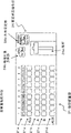
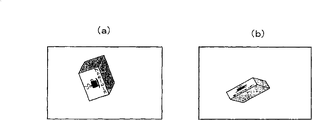
The image of text strings is inserted in captions/stack (superimposition) in the past in as the image of target.When to by texture when the lip-deep image of CG object inserts text strings by stack, according to the situation of texture face, for example at the texture face rotation having taken place, has dwindled, under the situation of distortion etc., will be difficult to recognize text strings.For example, (a) of Figure 28 shows the situation that the texture face has rotated, and Figure 28 (b) shows the reduced situation of texture face in addition.In these cases, be difficult to recognize text strings " コ one ヒ one カ Star プ ".
When making CG, if text strings is made as the CG object and is shown as the image of virtual three-dimensional space, then this literal can be recognized easily.But, when the image of texture is wanted in switching when using, be difficult to show and each image corresponding character string along with switching.In addition, when live wait to use, the insertion of text strings is to be undertaken by the part that operation is called as the keying function of effect converter (effect switcher), and wishes and can operate reliably.
The objective of the invention is to, be used at the CG that will make under the situation of live grade can be inserted into the position corresponding by the corresponding text strings of the image of texture with this image with watching easily.
The means of dealing with problems
Notion of the present invention is a kind of image processing apparatus, comprising:
Image generation unit, it generates computer graphic image based on the computer graphical data of description;
Image mapped unit, the object of the computer graphic image that it draws described image generation unit or the part of this object be as the texture target, and with texture image texture to the surface of this texture target; And
Superpositing unit, it is based on the positional information of the described texture target in the described computer graphic image, the computer graphic image that superimposed image has been added in described image mapped unit by texture with the corresponding position of described texture target on.
In the present invention, image generation unit generates computer graphic image based on the computer graphical data of description.In the case, by three-dimensional coordinate being decomposed into polygons (polygon) such as triangle, and draw the drafting that this polygon carries out integral image.In addition, the object of the computer graphical that the image mapped unit will be drawn by image generation unit or the part of this object be as the texture target, and with texture image texture to the surface of this texture target.
For example, from a plurality of input image datas, select a view data by texture image data selection unit.The image mapped unit will be based on the texture image texture of the view data of being selected by this texture image data selection unit to the surface of texture target.In the case, the operator is by changing the view data of being selected by texture image selected cell, and can change will be by the image of texture.
In addition, on the computer graphic image that superpositing unit has been added in the image mapped unit superimposed image by texture.In the case, based on the positional information of the described texture target in the computer graphic image, with superimposed image be added to the corresponding position of texture target on.
For example, from a plurality of input image datas, select a view data by the superimposed image data selected cell.The superpositing unit stack is based on the superimposed image of the view data of being selected by this superimposed image data selected cell.In the case, the operator is by changing the view data of being selected by the superimposed image selected cell, can change the image that will be applied images such as () text strings.In addition, for example generate superimposed image as computer graphic object by the superimposed image generation unit.
So, with texture image texture to the surface of texture target.In addition, based on the positional information of texture target, with in the superimposed image computer graphic image of texture image that has been added to texture with the corresponding position of texture target on.Thereby, can be inserted into by the image corresponding character string of texture with watching easily with the corresponding position of this image on.
In addition, for example can also comprise the information setting unit in the present invention, corresponding relation between one or more series in its setting texture image and the one or more series of superimposed image, and described superpositing unit is based on the corresponding relation of being set by the information setting unit, will with by texture to the corresponding superimposed image of lip-deep texture image of texture target be added to the corresponding position of this texture target on.In the case, when texture image with a plurality of series or superimposed image, also can with the image corresponding character string of texture be inserted into with watching easily with the corresponding position of this image on.
In addition, for example can also comprise surperficial designating unit in the present invention, its value by the predetermined attribute in the computer graphical data of description is selected to specify the texture target, and surperficial designating unit is specified the texture target at each series of texture image.Attribute for example be material definition, material definition with surface information etc.
In addition, for example can also comprise mode switch element in the present invention, it switches first pattern of using through the computer graphic image of texture, with second pattern of using other images different with this computer graphic image, and described superpositing unit is when being switched to described first pattern, positional information based on the texture target in the computer graphic image, the computer graphic image that superimposed image has been added in the image mapped unit by texture with the corresponding picture position of texture target on, and when being switched to second pattern, on the precalculated position of other images that then superimposed image are added to.
The invention effect
According to the present invention, positional information based on the texture target, with superimposed image be added to by in the computer graphic image that texture image texture is obtained on the surface of texture target, with this corresponding position of texture target on, thereby can be inserted into by the corresponding text strings of the image of texture with watching easily with the corresponding position of this image on.
Description of drawings
Fig. 1 is the block diagram that illustrates as the configuration example of the image processing apparatus of first embodiment;
Fig. 2 be illustrate material with the figure of example of surface information;
Fig. 3 is the figure that an example of the outward appearance that constitutes the control panel that synthesizes the blocked operation input part is shown;
Fig. 4 is the block diagram that the concrete configuration example of image generation unit and image mapped unit is shown;
Fig. 5 is the figure of configuration example that the functional block of image generation unit and image mapped unit is shown;
(a) of Fig. 6 and (b) be the figure that the example of texture image when carrying out texture and UV figure is shown;
Fig. 7 illustrates the figure that each face (polygonal part set) to the CG object is given different attribute;
(a)~(d) of Fig. 8 is the figure that the implication and the action example of the present invention of positional information are shown;
Fig. 9 is the figure of an example of computing method that is used for illustrating the positional information of image generation unit;
Figure 10 is the figure of another example of computing method that is used for illustrating the positional information of image generation unit;
Figure 11 is the figure of another example of computing method that is used for illustrating the positional information of image generation unit;
(a) of Figure 12 and (b) be the exemplary plot of the superimposed image of stack text strings on the CG image of texture image that has been illustrated in texture;
Figure 13 is the figure that illustrates as the configuration example of the image processing apparatus of second embodiment;
Figure 14 is the figure of outward appearance that an example of the control panel with image selection operation unit is shown;
(a) of Figure 15 and (b) be to be illustrated in that the GUI that shows when distributing the designated button row shows example and the GUI that shows when selecting output bus shows the figure of example;
Figure 16 is the figure that an example of the bus number of output bus and the mapping input corresponding tables that the corresponding relation between T1~T4 is imported in mapping is shown;
(a) of Figure 17 and (b) be the figure of an example that the image allocation table of the corresponding relation between the value (title) of mapping input T1~T4 and attribute is shown;
(a)~(f) of Figure 18 is the figure of an example that the image corresponding tables of the corresponding relation between texture image and the superimposed image is shown;
Figure 19 is the process flow diagram corresponding to the treatment step of a frame that the image mapped unit is shown;
Figure 20 is the process flow diagram corresponding to the treatment step of a frame that superpositing unit is shown;
Figure 21 is the precedence diagram that is illustrated in communication when carrying out Coordinate Calculation in the part different with the image mapped unit (different microcomputers) etc.;
Figure 22 is the block diagram that illustrates as the configuration example of the image processing apparatus of the 3rd embodiment;
Figure 23 is the block diagram that illustrates as the configuration example of the image processing apparatus of the 4th embodiment;
(a)~(e) of Figure 24 is the synthetic figure of embedding that is used to illustrate animation;
(a)~(f) of Figure 25 is the variation (motion) that is used to illustrate the CG image and embeds synthetic figure;
Figure 26 is the block diagram that another configuration example of image processing apparatus is shown;
Figure 27 is the block diagram that the another configuration example of image processing apparatus is shown;
(a) of Figure 28 and (b) be to illustrate by the figure of the example images of texture when the lip-deep image of CG object has inserted text strings by stack.
Embodiment
Below the mode that is used to carry out an invention (below be called " embodiment ") is described.Illustrate in the following order and carry out.
1. first embodiment
2. second embodiment
3. the 3rd embodiment
4. the 4th embodiment
5. variation
<1. first embodiment 〉
[formation of image processing apparatus]
First embodiment of the present invention is described.Fig. 1 shows the configuration example as the image processing apparatus 100 of first embodiment.This image processing apparatus 100 has: CG (Computer Graphics: computer graphical) production unit 110, surperficial designating unit 120, network 130, image generation unit 140 and image mapped unit 150.In addition, this graphic processing facility 100 comprises auxiliary efferent 160, the synthetic switching part 170 of image, position transmitting element 180, synthetic switch control portion 190 and synthetic blocked operation input part 195.CG production unit 110, surperficial designating unit 120, image generation unit 140 and position transmitting element 180 are connected with network 130 respectively.
(a) definition of material
The definition of this material is the surface nature (appearance) of CG object.Comprise color, reflection mode, information such as luminous, concavo-convex in the definition of this material.And, comprise the information of texture in the definition of this material sometimes.Texture is that image is attached to method on the CG object as mentioned above, and it shows complicated apperance etc. when can alleviate the load of disposal system.Fig. 2 show material with the example of surface information.In addition, replace color, also specify texture sometimes.
(b) definition of geometry information Geometry
The information that comprises position coordinates about polygonal mesh, apex coordinate etc. in the definition of this geometry information Geometry.
(c) definition of video camera
The parameter that comprises video camera in the definition of this video camera.
(d) definition of animation
The information that comprises the various values in each key frame of animation in the definition of this animation.In addition, the temporal information that comprises each key frame of animation in the definition of this animation.Various information for example are the information of coordinate figure, size, tangent line vector, interpolation method, the variation of various information in animation etc. on time, position or summit of the key frame points of corresponding object (node).
(e) position of the node in the scene (object), direction, size, corresponding geometry information definition, corresponding material definition
These information are not scattered, for example are mapped by following.
Node ... geometry information
Node ... material (a plurality of)
Geometry information ... polygon set (a plurality of)
The polygon set ... material (in the material corresponding one) with node
Animation ... node
The description that constitutes a picture is called as scene.Each definition is called as the storehouse, and in scene by reference.For example, under the situation of the object that has two rectangular parallelepipeds, each object is described to a node respectively, and each node can be associated some in the material definition.Consequently, the object of each rectangular parallelepiped can be associated the material definition, thereby available color and the reflection characteristic that defines according to each material drawn.
Perhaps, gather by a plurality of polygons at the object of rectangular parallelepiped and to describe and polygon set can be associated under the situation of material definition, each polygon is gathered available different material and is defined and draw.For example, rectangular parallelepiped has 6 faces, but the object of rectangular parallelepiped is with three polygon set descriptions sometimes, and for example, three faces wherein are a polygon set, and a face is a polygon set, and two faces are a polygon set.Because each polygon set can be associated different material definition, therefore also can draw each face with different colors.In image mapped described later unit, the part of object or object (cutting unit of face or polygonal mesh etc.) is set as the target of texture.
Show example (part is taken passages example) below as the Collada file of CG data of description.For example, in this example, defined the material of title (value) for " 01MatDefault ".And the actual content of this material has been described should be with reference to the effect of " 01MatDefault-fx ".In addition, this example<library_visual_scenes in, described the geometry information definition of " #Box01-lib " defined in conjunction with the material of " 01MatDefault " and drawn.
[example of Collada file]
<library_materials>
<material id=" 01MatDefault " name=" 01MatDefault "〉the material definition
<instance_effect url=" #01MatDefault-fx "/〉 with reference to effect
</material>
</library_materials>
<library_effects>
<effect id=" 01MatDefault-fx " name=" 01MatDefault "〉this is the content of material
<profile_COMMON>
<technique?sid=″standard″>
<phong>
<emission>
<color?sid=″emission>0.0000000.0000000.0000001.000000</color
>
</emission>
<ambient〉painted here
<color?sid=″ambient″>0.588235?0.952941?0.9215691.000000</color>
</ambient>
<diffuse>
<color?sid=″diffuse″>0.588235?0.952941?0.9215691.000000</color>
</diffuse>
<specular>
<color?sid=″specular″>0.000000?0.000000?0.000000?1.000000</color>
</specular>
<shininess>
<float?sid=″shininess″>2.000000</float>
</shininess>
<reflective>
<color?sid=″reflective″>0.000000?0.000000?0.000000?1.000000</color>
</reflective>
<reflectivity>
<float?sid=″reflectivity″>1.000000</float>
</reflectivity>
<transparent>
<color?sid=″transparent″>1.000000?1.000000?1.000000?1.000000</colo
r>
</transparent>
<transparency>
<float?sid=″transparency″>0.000000</float>
</transparency>
</phong>
</technique>
</profile_COMMON>
</effect>
</library_effects>
<library_geometries>
<geometry?id=″Box01-lib″name=″Box01Mesh″>
<mesh>
<source?id=″Box01-lib-Position″>
<float_array id=" Box01-lib-Position-array " count=" 24 "〉positional information
Array
-4.673016?-8.585480?0.000000
4.673016?-8.585480?0.000000
-4.673016?8.585480?0.000000
4.673016?8.585480?0.000000
-4.673016?-8.585480?10.185543
4.673016?-8.585480?10.185543
-4.673016?8.585480?10.185543
4.673016?8.585480?10.185543
</float_array>
<technique_common>
<accessor?source=″#Box01-lib-Position-array″count=″8″stride=″3″>
<param name=" X " type=" float "/〉 the arrangement explanation of the array of positional information
<param?name=″Y″type=″float″/>
<param?name=″Z″type=″float″/>
</accessor>
</technique_common>
</source>
<source?id=″Box01-lib-UV0″>
<float_array id=" Box01-lib-UV0-array " count=" 24 "〉array of UV coordinate
0.0000000.000000, therefore have only 0 and 1 owing to be simple cube
1.0000000.000000
0.0000001.000000
1.0000001.000000
0.0000000.000000
1.0000000.000000
0.0000001.000000
1.0000001.000000
0.0000000.000000
1.0000000.000000
0.0000001.000000
1.0000001.000000
</float_array>
<technique_common>
<accessor?source=″#Box01-lib-UV0-array″count=″12″stride=″2″>
The explanation of UV coordinate
<param?name=″S″type=″float″/>
<param?name=″T″tyPe=″float″/>
</accessor>
</technique_common>
</source>
<vertices?id=″Box01-lib-Vertex″>
<input?semantic=″POSITION″source=″#Box02-lib-Position″/>
</vertices>
<polygons?material=″01MatDefault″count=″12″>
<input?semantic=″VERTEX″offset=″0″source=″#Box01-lib-Vertex″/
>
<input?semantic=″NORMAL″offset=″1″source=″#Box01-lib-Normal
0″/>
<input?semantic=″TEXCOORD″offset=″2″set=″0″source=″#Box0
1-lib-UV0″/>
<p〉00921113210</p〉vertex information
<p>3?3?10?1?4?8?0?5?9</p>
<p>4?6?8?5?7?9?7?8?11</p>
<p>7?9?11?6?10?10?4?11?8</p>
<p>0?12?4?1?13?5?5?14?7</p>
<p>5?15?7?4?16?6?0?17?4</p>
<p>1?18?0?3?19?1?7?20?3</p>
<p>7?21?3?5?22?2?1?23?0</p>
<p>3?24?4?2?25?5?6?26?7</p>
<p>6?27?7?72?8?6?32?9?4</p>
<p>2?30?0?0?31?1?4?3?23</p>
<p>4?33?3?6?34?2?2?35?0</p>
</polygons>
</mesh>
</geeometry>
</library_geometries>
<library_animations>
<animation?id=″Box01-anim″name=″Box01″>
<animation>
<source?id=″Box01-translate-animation-inputX″>
<float_array?id=″Box01-translate-animation-inputX-array″count=″4″>
0.000000 the moment that the X coordinate figure in 1.000000 1.033333 1.333333 animations changes
</float_array>
<technique_common>
<accessor?source=″#Box01-translate-animation-inputX-array″count=″4″
>
<param?name=″TIME″type=″float″/>
</accessor>
</technique_common>
</source>
<source?id=″Box01-translate-animation-outputX″>
<float_array?id=″Box01-translate-animation-outputX-array″count=″4″>
X coordinate figure in-43.404125-43.404125-23.897228 13.150181 animations itself
</float_array>
<technique_common>
<accessor?source=″#Box01-translate-animation-outputX-array″count=″
4″>
<param?name=″X″type=″float″/>
</accessor>
</technique_common>
</source>
<source?id=″Box01-translate-animation-intanX″>
<float_array?id=″Box01-translate-animation-intanX-array″count=″4″>
0.000000?0.000000?1.884578?-0.000000
</float_array>
<technique_common>
<accessor?source=″#Box01-translate-animation-intanX-array″count=″4″
>
<param?name=″X″type=″float″/>
</accessor>
</technique_common>
</source>
<source?id=″Box01-translate-animation-outtanX″>
<float_array?id=″Box01-translate-animation-outtanX-array″count=″4″>
0.000000?0.000000?16.961202?0.000000
</float_array>
<technique_common>
<accessor?source=″#Box01-translate-animation-outtanX-array″count=″4
″>
<param?name=″X″type=″float″/>
</accessor>
</technique_common>
</source>
<source?id=″Box01-translate-animation-interpolationX″>
<Name_array?id=″Box01-translate-animation-interpolationX-array″count
=″4″>
BEZIER?BEZIER?BEZIER?BEZIER
</Name_array>
<technique_common>
<accessor?source=″#Box01-translate-animation-interpolationX-array″c
ount=″4″>
<param?type=″name″/>
</accessor>
</technique_common>
</source>
<sampler?id=″Box01-translate-animationX″>
<input?semantic=″INPUT″source=″#Box01-translate-animation-inputX
″/>
<input?semantic=″OUTPUT″source=″#Box01-translate-animation-out
putX″/>
<input?semantic=″IN_TANGENT″source=″#Box01-translate-animatio
n-intanX″/>
<input?semantic=″OUT_TANGENT″source=″#Box01-translate-animat
ion-outtanX″/>
<input?semantic=″INTERPOLATION″source=″#Box01-translate-ani
mation-interpolationX″/>
</sampler>
<channel?source=″#Box01-translate-animationX″target=″Box01/translate.
X "/determine that here what animation information more than (target) be
</animation>
<library_visual_scenes>
<visual_scene?id=″RootNode″name=″RootNode″>
<node?id=″Box01″name=″Box01″>
<translate?sid=″translate″>-43.404125?0.6970370.000000</translate>
<rotate?sid=″rotateZ″>0?0?1?0.000000</rotate>
<rotate?sid=″rotateY″>0?1?0?0.000000</rotate>
<rotate?sid=″rotateX″>1?0?0?0.000000</rotate>
<scale?sid=″scale″>1.000000?1.000000?1.000000</scale>
<instance_geometry url=" #Box01-lib "〉with reference to the geometry information definition
<bind_material>
<technique_common>
<instance_material?symbol=″01MatDefault″target=″#01MatDefault″/
With reference to material
</technique_common>
</bind_material>
</instance_geometry>
</node>
</visual_scene>
</library_visual_scenes>
Turn back to Fig. 1, the synthetic switching part 170 of image has input selection portion 171, key processor (image adds the Ministry of worker) 176, mixer 177.Input selection portion 171 is selected a plurality of view data that input comes in and is connected with a plurality of output channels.That is, input selection portion 171 will optionally be connected to key source bus 172a from 9 incoming lines that a plurality of view data be imported in the outside, key is filled on bus 172b, background A bus 172c, background B bus 172d and the preparation input bus 174.The part that the key source bus 172a of input selection portion 171, key are filled bus 172b has constituted the superimposed image data selected cell.
Cross point switches group 173a carries out being connected separately at each place, point of crossing that 9 incoming lines and key source bus 172a intersect.Cross point switches group 173b fills each place, point of crossing that bus 172b intersects at 9 incoming lines and key and carries out being connected separately.The key source signal that key source bus 172a is extracted is sent to key processor 176.In addition, key is filled the key filling signal that bus 172b extracted and is sent to key processor 176.The key filling signal is the signal that overlaps on the background image as prospect, and the key source signal is the zone of specifying overlapping key filling signal, excision background image and the shape that forms, key filling signal with respect to the signal of the concentration of background image etc.
Cross point switches group 173c carries out being connected separately at each place, point of crossing that 9 incoming lines and background A bus 172c intersect.Cross point switches group 173d carries out being connected separately at each place, point of crossing that 9 incoming lines and background B bus 172d intersect.And cross point switches group 175 is carried out being connected separately at each place, point of crossing that 9 incoming lines and preparation input bus 174 intersect.The background B data that are extracted the background A data on the background A bus 172c and are extracted on the background B bus 172d are sent to mixer 177.In addition, the CG view data that is extracted on the preparation input bus 174 is sent to mixer 177.
Synthetic switch control portion 190 is based on the processing action of controlling mixer 177, input selection portion 171 and auxiliary efferent 160 from the control signal of synthetic blocked operation input part 195.From the control signal of operation inputting part 195 for example comprise the pattern appointed information of specifying the tupe in the mixer 177, selection indication information that the selection change action of the input picture in each cross point switches group is indicated etc.
In addition, synthetic switch control portion 190 has CG mode switch element 191.This CG mode switch element 191 is based on from the control signal of synthetic blocked operation input part 195 CG output mode and full frame output mode being switched.Here, the CG output mode has been to use in image mapped unit 150 by texture the pattern of the CG image of texture image.In addition, the full frame output mode is to use the pattern of other images different with the CG image.
Synthetic blocked operation input part 195 have be used for indicating the tupe of mixer 177 and the synthetic action of the ratio keying that advances and input selection portion 171 and auxiliary efferent 160 in the Switch of selection action etc. of input picture.Synthetic blocked operation input part 195 generates the control signal of the processing action that is used to control mixer 177, input selection portion 171 and auxiliary efferent 160 according to operator's operation input, and this control signal is sent to synthetic switch control portion 190.
For example, wait the numbering of specifying the tupe in the mixer 177 by numerical key or pushbutton switch.In addition, for example wait the numbering that specifies in input selection portion 171, assists the incoming line that makes each bus connection in the input part 160 by numerical key or pushbutton switch.In addition, for example by pushing away the ratio that advances (progression ratio) that moving of rail (fader switch) specified in the mixer 177.In addition, for example set the content of the tupe in the mixer 177 by the operation of Switch.
Should synthetic blocked operation input part 195 has the open operation unit 196 that constitutes by pushbutton switch etc.This open operation unit 196 is used to for the operator in that open under the above-mentioned CG output mode or close will be as the processing on the superimposed image stack (overlapping) of the foreground image CG image at image as a setting by mixer 177.
Fig. 3 shows an example of the outward appearance of the control panel that constitutes synthetic blocked operation input part 195.
On control panel, roughly be provided with button arrangement portion 21 and running status operating portion 24.Button arrangement portion 21 is provided with and is used for selective extraction and fills the key selection portion 21a of the picture signal on the bus, the background B selection portion 21c that is used for the background A selection portion 21b of the picture signal of selective extraction on the background A bus and is used for the picture signal of selective extraction on the background B bus to key source bus, key.In addition, button arrangement portion 21 is provided with and is used to select to propose the auxiliary output selection portion 21d that the picture signal on the bus 161 is selected in auxiliary output.
Each selection portion constitutes each of 9 incoming lines and the same form button of selecting of selecting that is connected of corresponding output bus by being used for, and the button of choosing is lighted.For example, in the example of Fig. 3, select incoming line " 8 ", select incoming line " 3 ", select incoming line " 5 ", select incoming line " 5 " by auxiliary output selection portion 21d by background B selection portion 21c by background A selection portion 21b by key selection portion 21a.In addition, in the literal display part 21e on the top that is arranged at each pushbutton switch, show the title that is used to discern to the input picture of each incoming line input.
In key selection portion 21a, by pressing next pushbutton switch, key source bus, key are filled both connections of bus and are switched.Suppose that having preestablished this moment is to select line identical in the incoming line or select different lines at each bus.For example carry out following setting: when selecting pushbutton switch " 1 ", the key source bus is connected to incoming line " 1 ", and key is filled bus and then is connected to adjacent incoming line " 2 ".
In forward travel state operating portion 24, be provided with push rod 24a.By from an end of sliding scale to the other end this push rod 24a that slides, can change the forward travel state of the processing in the mixer 177.In addition, be provided with switch target selection portion 24b on the top of forward travel state operating portion 24, this switch target selection portion 24b selects the target that will change by the operation of slide bar 24a as still picture signal as a setting of key signals by pushbutton switch.In addition, also be provided with the 24c of direction setting portion on the top of forward travel state operating portion 24, the 24c of this direction setting portion sets the direction of transformation by pushbutton switch.
In addition, the image generation unit 140 various values that also will be used for carrying out the key frame of animation are kept in the storer.For example, when drafting is present in polygon set in the geometry information of certain node, draw this polygon set with reference to this geometry information and the material definition that is mapped and according to the appointment of its color etc.Under the situation of animation, current time is advanced on frame ground one by one, and determine each value by each value in the key frame before and after the current time is carried out interpolation, draw thus.
Send appointed information from surperficial designating unit 120 to this image generation unit 140 as the part (cutting unit of face or polygonal mesh etc.) of the object of the CG of the target of wanting the texture input picture or object.Image generation unit 140 control charts are as map unit 150, so that the input picture texture is arrived on the surface of the predetermined polygon (polygon set) shown in this appointed information.
On the surface by the texture target of surperficial designating unit 120 appointments among the CG that image mapped unit 150 is drawn the input picture texture to image generation unit 140.This image mapped unit 150 is installed into one with above-mentioned image generation unit 140.The hardware based action based on the control of software and GPU (Graphics Processing Unit, graphic process unit) etc. that this image mapped unit 150 can pass through on the CPU (Central Processing Unit, central processing unit) realizes.Control Software is specified the polygon that carries out texture to gather and is given hardware with its indication.
[configuration example of image generation unit and image mapped unit]
Fig. 4 shows the concrete configuration example of image generation unit 140 and image mapped unit 150.Image generation unit 140 and image mapped unit 150 comprise image input and output portion 141, GPU 142, local storage 143, CPU 144 and primary memory 145.In addition, image generation unit 140 and image mapped unit 150 comprise peripheral unit control portion 146, hard disk drive (HDD) 147, ethernet circuit 148a and network terminal 148b.In addition, image generation unit 140 and image mapped unit 150 comprise USB (Universal Serial Bus, USB (universal serial bus)) terminal 149 and SDRAM (SynchronousDRAM, synchronous DRAM) 151." Ethernet " is registered trademark.
Image input and output portion 141 input is used to carry out the view data of texture, and output by texture suitably based on the view data of the CG image of the image of view data.These image input and output portion 141 maximums can be imported the view data of four series, and the maximum view data that can export four series.Here processed view data for example is the view data by HD-SDI (High Definition television-Serial Digital Interface, the high definition serial signal interface) specification of SMPTE 292M regulation.GPU 142 and primary memory 145 can carry out access to image input and output portion 141 comparably.
Fig. 5 shows the configuration example of the functional block of above-mentioned image generation unit 140 and image mapped unit 150.This image generation unit 140 and image mapped unit 150 comprise the functional block of image input part 152, texture image storage part 153, CG control part 154, CG drafting portion 155, texture coordinate control part 156, frame buffer 157 and image efferent 158.
By increasing image input part 152 and texture image storage part 153 in couples, can increase the series of image input.In addition, by increasing frame buffer 157 and image efferent 158 in couples, can increase the series of image output.
(a) of Fig. 6 and (b) show a texture image when carrying out texture and the example of UV figure.(a) expression texture image of Fig. 6, (b) expression UV figure of Fig. 6.Here, UV figure is expression map by the coordinate representation on this paper when the surface with certain object (node) is thought of as paper.When plane earth is expanded this map, the point on this plane (x, y) with the lip-deep point of object (u, v) corresponding.Therefore, by carrying out that texture image is attached to processing on the UV figure, can carry out texture image is attached to the lip-deep texture of object.(b) of Fig. 6 shows texture image is attached to state on the UV figure.
Turn back to Fig. 1, as mentioned above, surperficial designating unit 120 specifies input picture by the texture target of texture.And surperficial designating unit 120 sends this appointed information via network 130 to image generation unit 140.This surface designating unit 120 is for example realized by GUI (Graphical User Int erface, graphic user interface).
The value (title) of the attribute of the part that is given to object or object in the surface designating unit 120 demonstration CG data of description is therefrom selected for the operator as options, selects the part as the object or the object of texture target thus.Surface designating unit 120 sends to image generation unit 140 with the value that is given to the attribute of texture target in the CG data of description as the appointed information of texture target.
In the present embodiment, in the CG data of description, the texture target by with material definition be mapped be endowed the material definition with the attribute of surface information etc.For example, under situation about the material definition being corresponded on the CG object, all masks of CG object have identical surface properties (color etc.).For example under the situation of the metallic article of stone or soupspoon shape, can make CG by such corresponding relation.
On the other hand, multiple articles has different surface properties at its each face, even pencil for example, at around it, core, the wood grain of being cut etc. also have different surface properties respectively.Making under the situation of such article of CG, also various piece can made different CG objects and they are made up.But, in the case, as shown in Figure 7, with article as a CG object and to each face (polygonal part set) to give the operation that different attributes makes CG also be easier.
In general, carry out following operation in the operation making of CG object: the polygon set that will constitute the surface is divided into several parts, the material definition is corresponded on each part, and be used for the UV coordinate figure of texture for polygonal each the fixed point decision of target.Generate the CG data of description corresponding with aforesaid operations.By in such CG data of description, using the present invention, can be on the part on the surface of CG object with the input picture texture.
The positional information of the texture target that position transmitting element 180 will be sent via network 130 from image generation unit 140 sends to the key processor 176 of the synthetic switching part 170 of above-mentioned image.Key processor 176 is adjusted key filling signal and key source signals, so that the superimposed images such as text strings that will superpose are added in the CG view data of image as a setting and the corresponding position of texture target.When having taken place along with the preceding of animation and then texture target when mobile, positional information is sent to position transmitting element 180 according to each frame that moves (usually frame by frame or by the place) has taken place from image generation unit 140, and then is sent to key processor 176.
[explanation of positional information]
Further location information describes.(a)~(d) of Fig. 8 shows the implication of positional information and the action example of this invention.
(a) of Fig. 8 is the figure of the position coordinates on the explanation picture.Laterally x and vertically y be set to the value that occupies the size of picture with-100 to+100 simultaneously.Owing to be relative coordinate, even therefore identical with coordinate difference on the y at x, the length on the real screen is also different.(b) of Fig. 8 is the example of foreground image (superimposed image that will superpose).
(c) of Fig. 8 illustrates according to positional information (50,20) stack (overlapping) result's the figure of the foreground information shown in (b) of Fig. 8.But, the frame of broken lines of the stack image of (overlapping) is not in fact drawn.In order to describe, be shown in broken lines frame.Rectangular parallelepiped in the background is the example of CG generation figure.
(d) of Fig. 8 illustrates according to the superposeed figure of the foreground image shown in (b) of Fig. 8 of positional information (50,20).In this example, with foreground image narrow down to 50% and move after superpose.It doesn't matter with positional information in the processing of dwindling like this, but set separately in addition from synthetic blocked operation input part 195 grades, and carried out by synthetic switch control portion 190 operating key processors 176.
Example calculation to the positional information in the image generation unit 140 describes.
In this embodiment, determine that the face of CG object of property value unanimity is as the target face of texture.Position transmitting element 180 sends the coordinate figure of this face as positional information to key processor 176.As an example, being calculated as follows of coordinate figure carried out.
Target face is not above-mentioned (c) as Fig. 8, the simple rectangle shown in (d) usually, but the more complicated Virtual Space solid that is formed by the polygon set, and each summit that constitutes this solid is projected on the picture respectively and is displayed on certain coordinate.Although as the set on summit, there are a lot of coordinate figures, can access so-called bounding box shown in Figure 9 by these x, y maximal value and minimum value separately.Image generation unit 140 is obtained the center (the Centromedian coordinate figure of maximal value and minimum value) of this bounding box as positional information.
Another example of the computing method of location information describes.Each summit of the polygon set of target face is endowed the texture coordinate when carrying out texture.Texture coordinate is also referred to as UV coordinate etc. as shown in figure 10, and the U suitable with the x coordinate, the V suitable with the y coordinate also have the value in from 0 to 1 the scope.(U, V) coordinate figure is the position of (0.5,0.5) thereby the centre by the image of texture is plotted in.Image generation unit 140 calculates and UV just in time is the suitable coordinate figure in summit of (0.5,0.5), as positional information.There is not UV just in time under the situation for the point of (0.5,0.5), by obtaining the coordinate figure suitable with (0.5,0.5) to carrying out linear interpolation between the summit.
In above-mentioned Figure 10, the central authorities of line segment that connect the summit of summit that the texture coordinate figure be (0,1) and (1,0) are that texture coordinate is the point of (0.5,0.5).Under the situation of Figure 11, connect the summit and (0.8 of texture coordinate figure (0,1), the central authorities of the line segment on summit 0) are that texture coordinate is (0.4,0.5) point, from this point to the U direction moved 0.1 (to 0.8 1/4) the position be texture coordinate is the point of (0.5,0.5).The UV coordinate figure is that the position of (0.5,0.5) is not limited to a place in the polygon, therefore in this mode, if a plurality of such positions are arranged, then with one of them as positional information.
Also can constitute: in addition be used for stack behind the certain value on the positional information of as above-mentioned each example, calculating.For example, can with on the picture downwards or above be offset the position of certain value as the lap position.Perhaps in first example, also the height (length of y direction) to bounding box can be multiply by fixed value and value (for example half) be added on the positional information y.For x direction or vergence direction too.
In addition, when the value shown in the positional information has exceeded the scope (100 to+100) of picture or for example exceeded-80 to+80 scope, also can revise, so that it falls in the described scope (for example, surpass at 100 o'clock be made as 100 etc.).Therefore because purpose is to be used for stack, even on for the picture that is added to rightly and implement under these simple situations of revising (conversion), the advantage that obtains positional information from image generation unit 140 is also constant.
[the action example of image processing apparatus]
Action example to image processing apparatus shown in Figure 1 100 describes.
In CG production unit 110, make software by CG and generate the CG data of description that is used to generate predetermined CG image.So the CG data of description that generates in CG production unit 110 is sent to image generation unit 140 and surperficial designating unit 120 via network 130.
In surperficial designating unit (GUI) 120, the object in the CG data of description or the value (title) that is given to the attribute of object as options, and are specified the texture target of wanting the texture input picture by operator's operation.This appointed information (value of attribute) sends to image generation unit 140 from surperficial designating unit 120.
Here, to being in the CG output mode and the situation that the stack of the foreground image of CG image is set to unlatching being described.
Image mapped unit 150 will be mapped on the surface of texture target based on the image texture of the view data T1 that is obtained by auxiliary efferent 160 under the control of image generation unit 140.And, in texture on the surface of texture target be output on the lead-out terminal 140a that draws from image generation unit 140 based on the view data Vout of the CG image of the image of view data T1.
This view data Vout is imported on the incoming line " 9 ".As mentioned above, the preparation input bus 174 of the input selection portion 171 of the synthetic switching part 170 of image is connected with incoming line " 9 " by cross point switches group 175.Therefore, the view data Vout of above-mentioned CG image is extracted on this preparation input bus 174, thus this view data Vout as a setting data be fed to mixer 177.
In addition, image generation unit 140 is obtained the positional information of texture target, and this positional information is sent to the key processor 176 of the synthetic switching part 170 of image from position transmitting element 180.These key processor 176 position-based information are applied to the mobile adjustment of the superimposed images such as text strings of CG image.That is, adjust key filling signal, key source signal, so that superimposed image is superimposed on the position corresponding with the texture target.
So key filling signal, the key source signal of adjusting through key processor 176 is sent to mixer 177.Mixer 177 uses the view data Vout of CG images and key filling signal, key source signal, and superimposed images such as text strings are added on the CG image of image as a setting.At this moment, superimposed image is superimposed on the corresponding position of texture target with the CG image.
By the operation from operator's synthetic blocked operation input part 195, the view data that is extracted on other backgrounds A bus 172c, the background B bus 172d also is used in the synthetic processing of mixer 177 as required.The view data that obtains at this mixer 177 is output to the outside as final output by output line 178.
Then, situation about being under the total painting surface model is described.In the case, in mixer 177, do not use from the view data that transmits of preparation input bus 174, promptly from the CG view data of image generation unit 140 outputs.In addition, in key processor 176, do not use the positional information that transmits from position transmitting element 180.That is, in key processor 176, do not carry out the mobile adjustment of superimposed image.Perhaps, in key processor 176, carry out the mobile adjustment of superimposed image according to other the mobile indication of indicating from synthetic blocked operation input part 195 grades.
Another action example under the total painting surface model is described.Under the situation that is in the total painting surface model, different with above-mentioned action example, mixer 177 can use the view data that transmits from preparation input bus 174.But the incoming line that is connected with preparation input bus 174 is not the incoming line " 9 " from image generation unit 140 input CG view data, but is set to other incoming line by operator's operation.In the case, the CG view data from image generation unit 140 outputs is not used yet.
As mentioned above, the identical foreground image that under arbitrary pattern of CG output mode and total painting surface model, all superposes.But only the operation according to CG mode switch element 191 judges whether this superposed positions is matched on the position corresponding with the texture target, and automatically with whether use the CG image whether to be used interlock, improved operability thus.
In image processing apparatus shown in Figure 1 100, with texture image texture on the surface of texture target.In addition, based on the positional information of texture target, with superimposed images such as text strings be superimposed upon texture the texture image the CG image with this corresponding position of texture target on.Therefore, in this image processing apparatus 100, can be inserted into the position corresponding by corresponding text strings of image of texture etc. with this image with watching easily.
(a) of Figure 12 and (b) shown the example of the superimposed image that superposeed on the CG image of texture image in texture.(a) of Figure 12 shows the situation that the texture face has rotated, but text strings is inserted on the position corresponding with the texture image with upright state.In addition, (b) of Figure 12 show the texture face reduced situation, but text strings with reduced and not upright state be inserted in the corresponding position of texture image on.
In addition, in image processing apparatus shown in Figure 1 100, by auxiliary efferent 160, optionally extract some in the view data that is imported into 9 incoming lines and view data be provided for image mapped unit 150 as texture image data T1.Therefore, the operator changes the view data of being extracted by auxiliary efferent 160 by the operation that utilizes synthetic blocked operation input part 195 to carry out, and can regularly the texture image changed into desired images arbitrarily thus.
In addition, in image processing apparatus shown in Figure 1 100, optionally extract some in the view data that is imported into 9 incoming lines by the input selection portion 171 of the synthetic switching part 170 of image, and with it as superimposed image data (key filling signal, key source signal).Therefore, the operator changes the view data of being extracted by input selection portion 171 by the operation that utilizes synthetic blocked operation input part 195 to carry out, and can regularly superimposed image changed into desired images arbitrarily thus.
Action when switching CG pattern and total painting surface model removes as above-mentioned only use location information under the CG output mode, also can dwindle processing according to the value of dwindling of other setting.That is, under the CG output mode, after dwindling the foreground image that will superpose, move this foreground image according to positional information again and superpose according to setting value.
<2. second embodiment 〉
[formation of image processing apparatus]
Second embodiment of the present invention is described.Figure 13 shows the configuration example as the image processing apparatus 100A of second embodiment.In this Figure 13, also suitably omit its explanation for the part mark same numeral corresponding with Fig. 1.
This image processing apparatus 100A has: CG production unit 110, surperficial designating unit 120A, network 130, image generation unit 140A and image mapped unit 150a.In addition, this graphic processing facility 100A comprises matrix switch 210, image selection operation unit 230 and superpositing unit 240.CG production unit 110, surperficial designating unit 120A, image generation unit 140A and image selection operation unit 230 are connected with network 130 respectively.
Matrix switch 210 has constituted the image selected cell, and this image selected cell optionally extracts a view data from a plurality of input image datas.This matrix switch 210 comprises: 9 incoming lines, 8 output buss 211~218 and cross point switches group 221~228.Output bus 211~214th is used for providing to image mapped unit 150A the bus of texture image data T1~T4.In addition, output bus 215~218th is used for providing to superpositing unit 240 bus of superimposed image data S1~S4.
In addition, cross point switches group 225~228 is carried out being connected separately at each place, point of crossing that 9 incoming lines and output bus 215~218 intersects.Based on user's image selection operation, the connection Be Controlled of this cross point switches group 225~228, thus be input to some optionally being outputed on the output bus 215~218 in 9 view data on the incoming line.This output bus 215~218 constitutes the output line of superimposed image data S1~S4.The action of the on/off of each cross point switches of cross point switches group 221~228 is because to being switched by the view data of continuous frame data structure, therefore carries out in the vertical blanking interval as the gap of frame.
The operation input of the indication of above-mentioned matrix switch 210 is issued in 230 acceptance of image selection operation unit.This image selection operation unit 230 has control panel 260, and described control panel 260 has the button rows that the on/off of the switch of each cross point switches group of matrix switch 210 is operated.
Figure 14 shows the outward appearance of an example of control panel 260.This control panel 260 is configured to arrange on above-below direction along the two row button rows 271,272 that left and right directions extends.Button rows 272 is used to the on/off of the switch of each cross point switches group of matrix switch 210 is operated.This button rows 272 is by constituting each of incoming line and the same form button of selecting of selecting that is connected of the output bus of correspondence, and the button of choosing is lighted.
On control panel 260 with the button rows 272 corresponding literal display parts 273 that are provided with.On this literal display part 273, show the literal that is used to discern to the input picture of each incoming line input.This literal display part 273 for example is made of LCD display elements such as (Liquid Crystal Display, LCD).
Button rows 271 is designated button row, is used to specify the selection operation that button rows 272 is used for the view data of that output bus.This button rows 271 constitutes by selecting same form button, and the button of choosing is lighted.On control panel 260 with the button rows 271 corresponding literal display parts 274 that are provided with.Each button that shows expression button rows 271 on this literal display part 274 is used to the literal of selection operation of the view data of which output bus.This literal display part 274 for example is made of display elements such as LCD.
For example can realize that each button with button rows 271 is used on the selection operation of view data of which output bus by GUI (Graphical User Interface).(a) of Figure 15 shows at the GUI that distributes button rows (designated button row) to show at 271 o'clock and shows example.In this GUI showed, 8 buttons of button rows 271 were represented with " 1 "~" 8 ".The operator is by operation and should show the options of output bus in " 1 "~" 8 " corresponding " selector button ", and selects the output bus of expectation from this options, the output bus of expectation can be distributed to each button thus.
(b) of Figure 15 shows the GUI that shows and shows example when selecting this output bus.In this GUI showed, the output bus 215~218 that constitutes the output line of superimposed image data S1~S4 was shown as options by " S1 "~" S4 ".In addition, in this GUI showed, for the output bus 211~214 to the output line that constitutes texture image data (mapping input) T1~T4 distributes button, the value (title) that shows predetermined attribute was as options.As attribute, by operator's operation, for example from material definition, material definition with surface information etc. set attribute arbitrarily.Here, the operator sets the attribute that is used to specify texture target (part of object or object).Perhaps, also can in system, set an attribute in advance.
Image selection operation unit 230 extracts the value (title) of the attribute that sets from the CG data of description that is generated by CG production unit 110, and this value is shown in the GUI demonstration as options.GUI at Figure 15 (b) shows in the example, shows the situation of material definition as attribute of setting, and the title of material definition is shown as options.Show in the example that at this GUI " Metal-1 ", " Metal-2 ", " Material-Def1 ", " Material-Def2 ", " Material-Def3 " are the titles of material definition.
GUI at Figure 15 (a) shows in the example, has selected " S1 "~" S4 " at " 1 "~" 4 ".In addition, " Metal-1 ", " Material-Def3 " have been selected at " 5 ", " 6 ".Do not carry out any selection at " 7 ", " 8 ".
As mentioned above, matrix switch 210 has 8 output buss, and each output bus is specified with bus number " 1 "~" 8 ".In addition, as mentioned above, first of matrix switch 210 imported (texture image data) T1~T4 to the 4th output bus to image mapped unit 150A input mapping.Image selection operation unit 230 or its peripheral microcomputer have the mapping input corresponding tables as shown in figure 16 of having stored this connection state.This mapping input corresponding tables is stored as the setting corresponding with line, does not change as long as line just changes.
When as " 5 " of Figure 15 (a), " 6 " certain button having been selected the value (title) of predetermined attribute, the output bus that is not assigned with as yet in the bus number 1~4 is distributed to this button in image selection operation unit 230.In the case, this output bus becomes the output bus of the view data that is used to export following image, and described image is will be by the lip-deep image of texture to the part of the object of the value that has been endowed the predetermined attribute of choosing (title) or object.And image selection operation unit 230 is which information among mapping input T1~T4 sends to surperficial designating unit 120A via network 130 with the information of the value (title) of the predetermined attribute chosen and expression based on the mapping input of the output bus that distributes target.
Shown in Figure 15 (a),, further describe with to " 5 " selection " Metal-1 ", the situation to " 6 " selection " Material-Def3 " is an example afterwards.
At first, when " 5 " had been selected " Metal-1 ", output bus 211 was distributed to the button of " 5 " in image selection operation unit 230.Output bus 211 becomes the data bus of the view data that is used to export following image, described image be with material definition " Metal-1 " thus the part of object that is mapped or object be used as the texture target will be by the lip-deep image of texture to the part of this object or object.And image selection operation unit 230 sends to surperficial designating unit 120A with the information of material definition " Metal-1 " and mapping input T1 via network 130.
Then, when " 6 " had been selected " Material-Def3 ", output bus 212 was distributed to the button of " 6 " in image selection operation unit 230.Output bus 212 becomes the output bus of the view data that is used to export following image, described image be with material definition " Material-Def3 " thus the part of object that is mapped or object be used as the texture target will be by the lip-deep image of texture to the part of object or object.And image selection operation unit 230 sends to surperficial designating unit 120A with the information of material definition " Material-Def3 " and mapping input T2 via network 130.
In the above description, certain button for button rows 271 has been described, only can have selected the value (title) of a predetermined attribute.But also can consider certain button is allowed the formation of the value (title) of a plurality of predetermined attributes of selection.In the case, the object that is mapped with a plurality of property values of choosing or the part of object are used as the texture target, and in its surface texture based on the image of the output image data of the output bus that is assigned with certain button.In the case, with certain button corresponding character display part 274 on show a plurality of property values (title).But,, then show the property value of or displayable number if be difficult to show a plurality of property values (title).
(a) of Figure 17 shows an example of image allocation table.This example is as above-mentioned example when having selected " Material-Def3 " to " 5 " selection " Metal-1 " and to " 6 " like that in the image selection operation unit 230 shown in Figure 15 (a).In addition, Figure 17 (b) shows another example of image allocation table.This example is as above-mentioned example when having selected " Material-Def3 " to " 5 " selection " Metal-1 " and " Material-Def3 " and to " 6 " in image selection operation unit 230.In this image allocation table, T1~T4 composing images identifier.
In the image processing apparatus 100A of Figure 13, send the view data T1~T4 of four series to image mapped unit 150A from the output bus 211~214 of matrix switch 210.In addition, in the image processing apparatus 100A of Figure 13, send the view data S1~S4 of four series to superpositing unit 240 from the output bus 215~218 of matrix switch 210.Surface designating unit 120A makes the corresponding relation of texture image and superimposed image, and will represent that the image corresponding tables of this corresponding relation is set among the image generation unit 140A via network 130.Surface designating unit 120A for example make the operator from superimposed image data S1~S4, selects will with each superimposed image data that is mapped of texture image data T1~T4, and generation corresponding relation.
(a)~(f) of Figure 18 shows an example of image corresponding tables.In (a) of Figure 18, view data S1 is corresponded to view data T1.Under this corresponding relation, when based on the image of view data T1 by texture to the surface of the texture target corresponding the time with it, based on the image of view data S1 be added to the corresponding position of this image on.
In (b) of Figure 18, view data S1, S2 are corresponded to view data T1.Under this corresponding relation, when based on the image of view data T1 by texture to the surface of the texture target corresponding the time with it, based on the image of view data S1, S2 be added to the corresponding position of this image on.
In (c) of Figure 18, view data S1 is corresponded to view data T1, and view data S2 is corresponded to view data T4.Under this corresponding relation, when based on the image of view data T1 by texture to the surface of the texture target corresponding the time with it, be added on the position corresponding based on the image of view data S1 with this image.In addition, when based on the image of view data T4 by texture to the surface of the texture target corresponding the time with it, be added on the position corresponding based on the image of view data S2 with this image.
In (d) of Figure 18, view data S1 is corresponded to view data T1~T4.Under this corresponding relation, when based on the image of view data T1~T4 by texture to the surface of the texture target corresponding the time with it, be added on the position corresponding based on the image of view data S1 with this image.
In (e) of Figure 18, view data S1, S2 are corresponded to view data T1, and view data S2 is corresponded to view data T3.Under this corresponding relation, when based on the image of view data T1 by texture to the surface of the texture target corresponding the time with it, be added on the position corresponding based on the image of view data S1, S2 with this image.In addition, when based on the image of view data T3 by texture to the surface of the texture target corresponding the time with it, based on the image of view data S2 be added to the corresponding position of this image on.
In (f) of Figure 18, view data S1~S4 is corresponded to view data T3.Under this corresponding relation, when based on the image of view data T3 by texture to the surface of the texture target corresponding the time with it, be added on the position corresponding based on the image of view data S1~S4 with this image.
Image generation unit 140A generates three-dimension space image, is the CG image based on the CG data of description of being made by CG production unit 110.Image generation unit 140A information such as each definition are kept in the storer, and the corresponding relation between these information also is saved as data structure after reading in the CG data of description.In addition, the image generation unit 140A various values that will be used for carrying out the key frame of animation also are kept at storer.
For example, when the set of the polygon in the geometry information of drawing certain node,, and draw this polygon set according to the appointment of its color etc. with reference to this geometry information and the material definition that is mapped.Under the situation of animation, current time is advanced on frame ground one by one, and determine each value by each value in the key frame before and after the current time is carried out interpolation, draw thus.
In this image generation unit 140A, as mentioned above, set image allocation table (with reference to the (a) and (b) of Figure 17) by surperficial designating unit 120A.Image generation unit 140A comes control chart as map unit 150A based on this image allocation table.In the case, image generation unit 140A controls, make texture on the surface of texture target of value of each attribute of in being endowed table, having existed based on the image of the paired mapping input of the value (title) of this attribute.
In addition, in this image generation unit 140A, as mentioned above, set image corresponding tables (with reference to (a)~(f) of Figure 18) by surperficial designating unit 120A.Image generation unit 140A controls superpositing unit 240 based on this image corresponding tables.In the case, image generation unit 140A controls, when making the image of the texture image data that in having shone upon, existed based on table, superpose based on the image of the paired superimposed image data of this view data.
Carry out texture by the polygonal surface of surperficial designating unit 120A appointment in the polygon that image mapped unit 150A is drawn image generation unit 140A.In the case, on the surface of the texture target of the value of each attribute that image mapped unit 150A has existed in being endowed the image allocation table, texture based on the image of the paired mapping of the value (title) of this attribute input.This image mapped unit 150A and above-mentioned image generation unit 140A are installed into one, and can realize by the hardware based action based on the control of software and GPU etc. on the CPU.Control Software is specified the polygon that carries out texture to gather and is given hardware with its indication.
With the image production part 140 of above-mentioned image processing apparatus 100 shown in Figure 1 similarly, image generation unit 140A calculates in image mapped unit 150A by texture based on the positional information of the target of the image of each view data T1~T4 (with reference to figure 9~Figure 11).Superpositing unit 240 is based on the positional information of texture target, will be based on the image overlay of superimposed image data to the position corresponding with this texture target.This superpositing unit 240 is installed into one with above-mentioned image generation unit 140A.
In addition, also can the setting operation input block, with can be at each superimposed image data, the opening and closing of operation stack.Under the situation of carrying out corresponding texture, also can indicate whether to superpose by manual operation.
[the action example of image processing apparatus]
Action example to image processing apparatus 100A shown in Figure 13 describes.In CG production unit 110, make software by CG and generate the CG data of description that is used to generate predetermined CG image.So the CG data of description that generates in CG production unit 110 is sent to image generation unit 140A and surperficial designating unit 230A via network 130.
Image selection operation unit 230 distributes the button of the button rows (designated button row) 271 of control panels 260 by operator's operation to the output bus 211~214 of the output line of composing images data (mapping input) T1~T4.In the case, come to distribute successively by the value (title) of selecting predetermined attribute from output bus 211.
The attribute that is used to specify texture target (part of object or object) is set in this image selection operation unit 230 by operator's operation.Here, attribute be material definition, material definition with surface information etc.Above-mentioned predetermined attribute promptly is the attribute of so setting by operator's operation, and the value of the attribute of choosing (title) is to extract from the CG data of description that is generated by CG production unit 110.
Be assigned with the output bus of button of the button rows 271 of control panel 260 in the output bus 211~214 about matrix switch 210,, can have changed the output image data (mapping input) of this output bus by the operation of button rows 272.In the case, as output image data, optionally output is imported into some in the view data of 9 incoming lines.
When by image selection operation unit 230 when output bus 211~214 some distributed the button of button rows 271 of control panel 260, from image selection operation unit 230 to surperficial designating unit 120A via network 130 transmission information.This information comprises that the information of value (title) of selected predetermined attribute and expression are which information among mapping input T1~T4 based on the mapping input of the output bus that distributes target.
In addition, surperficial designating unit 120A makes the corresponding relation between texture image and the superimposed image, and will represent that the image corresponding tables of this corresponding relation is set among the image generation unit 140A via network 130.In the case, surperficial designating unit 120A for example make the operator from superimposed image data S1~S4, select will with each superimposed image data that is mapped of texture image data T1~T4, and generate corresponding relation.
Image generation unit 140A generates three-dimension space image, is the CG image based on the CG data of description of being made by CG production unit 110.In this image generation unit 140A, as mentioned above, set the image allocation table by surperficial designating unit 120A.Image mapped unit 150A carries out texture under the control of image generation unit 140A.That is, on the surface of the texture target of the value (title) of each attribute that image mapped unit 150A has existed in being endowed the image allocation table, texture based on the image of the paired mapping of the value (title) of this attribute input.
In addition, in this image generation unit 140A, as mentioned above, set the image corresponding tables by surperficial designating unit 120A.Superpositing unit 240 under the control of image generation unit 140A, with superimposed image be added to image mapped unit 150A by texture the CG image on.That is, during the image of the texture image data that in having shone upon, existed based on the image corresponding tables, superpositing unit 240 stack based on the image of the paired superimposed image data of these texture image data.
Image generation unit 140A calculates the positional information of the texture target in the CG image.Superpositing unit 240 is based on the positional information of texture target, will based on the image overlay of superimposed image data to this corresponding position of texture target on.And, texture texture image and be output on the lead-out terminal 140a that draws from image generation unit 140A at the CG view data Vout of the corresponding superimposed image that superposeed on the position corresponding with this image.
The process flow diagram of Figure 19 shows the treatment step corresponding to a frame of image mapped unit 150A.
Image mapped unit 150A begins to handle in step ST1, transfers to the processing of step ST2 afterwards.In this step ST2, image mapped unit 150A receives the information of importing selected property value at each image from image generation unit 140A.This information is present in the image allocation table that is set among the image generation unit 140A as mentioned above.
Then, image mapped unit 150A is set at 1 with image input numbering i in step ST3.And, image mapped unit 150A in step ST4 with i image input Ti texture to the surface of the part (texture target) of the CG object of property value unanimity or CG object.
And image mapped unit 150A will be sent to superpositing unit 240 as positional information by the coordinate Pi on the picture of the face of texture in step ST5.When i image input Ti do not selected property value, image mapped unit 150A did not carry out the processing of above-mentioned step ST4 and step ST5 to this i image input Ti.
Then, image mapped unit 150A judges that in step ST6 whether input numbering i is less than the input number.As input numbering i during less than the input number, because the processing of all texture images inputs is not finished as yet, so image mapped unit 150A makes input numbering i increase progressively in step ST7, turns back to the processing of step ST4 afterwards.On the other hand, when i is numbered in input more than or equal to the input number, owing to finished the processing that all texture images are imported, so image mapped unit 150A end process in step ST8.
The process flow diagram of Figure 20 shows the treatment step corresponding to a frame of superpositing unit 240.
Then, superpositing unit 240 will be imported numbering i and be set at 1 in step ST13.And superpositing unit 240 decides superposed positions (lap position) according to coordinate Pi in step ST14.And superpositing unit 240 will be based on importing the doubling of the image of the corresponding superimposed image input of Ti to the lap position that determines with image in step ST14 in step ST15.
Then, superpositing unit 240 judges that in step ST16 whether input numbering i is less than the input number.As input numbering i during less than the input number, owing to do not finish as yet for the processing of all texture images inputs, so superpositing unit 240 makes input numbering i increase progressively in step ST17, turns back to the processing of step ST14 afterwards.On the other hand, when i is numbered in input more than or equal to the input number, owing to finished the processing that all texture images are imported, so superpositing unit 240 end process in step ST18.
In above-mentioned Figure 19, example shown in Figure 20, the calculating of coordinate Pi in image generation unit 140 with draw (texture) and carry out simultaneously.But also can adopt different therewith installation methods.
Figure 21 shows the order of communication of being illustrated in when carrying out Coordinate Calculation in the part (different microcomputers) different with image mapped unit 150A etc.The CG data of description of being made by CG production unit 110 is sent to surperficial designating unit 120A, is sent to superpositing unit 240 simultaneously.
In surperficial designating unit 120A, for example image identifier and material definition are mapped, generate the image allocation table.This image allocation table is sent to image generation unit 140A, thereby is used in the action of image generation unit with the CG data of description.In this example, the image allocation table is sent to superpositing unit 240 simultaneously.
In superpositing unit 240, the position calculation of face is in addition handled owing to not needing so not carrying out.Superpositing unit 240 similarly carries out stack with the treatment step of Figure 20 according to the coordinate figure that obtains.That is, calculating location (coordinate) can suitably change in enforcement of the present invention in which microcomputer.
When the drafting processing of image generation unit 140A etc. changed according to time of animation action etc., same information is also sent to superpositing unit 240, make and move according to identical parameter.Its reason is as follows: if not like this, then in animation action, be performed at the processing of different time, thereby cause dislocation.
In image processing system 100A shown in Figure 13, with texture image texture to the surface of texture target.In addition, based on the positional information of texture to picture, with superimposed images such as text strings be superimposed upon texture the texture image the CG image with this corresponding position of texture target on.Therefore, in this image processing apparatus 100A, can with above-mentioned image processing apparatus shown in Figure 1 100 similarly, will be inserted into the position corresponding by corresponding text strings of image of texture etc. with this image with watching easily.
In addition, in image processing apparatus 100A shown in Figure 13,, the image corresponding tables of representing the corresponding relation of texture image and superimposed image is set among the image generation unit 140A by surperficial designating unit 120A.And superpositing unit 240 decides based on this corresponding relation and will be added to and the corresponding locational image of texture image.Therefore, when texture image that has a plurality of series or superimposed image, also can be inserted into by the superimposed images such as the corresponding text strings of image of texture with watching easily with this corresponding position of texture image on.
In addition, in image processing apparatus 100A shown in Figure 13, the view data of optionally extracting by matrix switch 210 is provided for image mapped unit 150A as texture image data T1~T4.Therefore, the operator changes the view data T1~T4 that is extracted by matrix switch 210 by the operation that utilizes image selection operation unit 230 to carry out, and can regularly the texture image changed into desired images arbitrarily thus.
In addition, in image processing apparatus 100A shown in Figure 13, optionally obtain some with as superimposed image data S1~S4 in the view data that is imported into 9 incoming lines by matrix switch 210.Therefore, the operator changes the view data S1~S4 that is extracted by matrix switch 210 by the operation that utilizes image selection operation unit 230 to carry out, and can regularly superimposed image changed into desired images arbitrarily thus.
<3. the 3rd embodiment 〉
[formation of image processing apparatus]
The 3rd embodiment of the present invention is described, and Figure 22 shows the configuration example as the image processing apparatus 100B of the 3rd embodiment.In this Figure 22,, and suitably omit its explanation for the part mark same-sign corresponding with Fig. 1.
This image processing apparatus 100B has: CG production unit 110, surperficial designating unit 120, network 130, image generation unit 140B and image mapped unit 150B.In addition, this graphic processing facility 100B comprises auxiliary efferent 160B, image synthetic switching part 170B, position transmitting element 180B, synthetic switch control portion 190 and synthetic blocked operation input part 195.CG production unit 110, surperficial designating unit 120B, image generation unit 140B and position transmitting element 180B are connected with network 130 respectively.
The synthetic switching part 170B of image has input selection portion 171B, key processor 176a~176b and mixer 177B.The synthetic switching part 170 of the image of the image processing apparatus 100 of above-mentioned Fig. 1 only has an overlaying function portion (keyer, keyer).That is, have a key processor 176, and this key processor 176 is connected with key source bus 172a, key filling bus 172b.
The synthetic switching part 170B of image has four overlaying function portions (keyer).That is, have four key processor 176a, 176b, 176c, 176d.And key processor 176a fills bus 172b1 with key source bus 172a1, key and is connected, and key processor 176b fills bus 172b2 with key source bus 172a2, key and is connected.And key processor 176c fills bus 172b3 with key source bus 172a3, key and is connected, and key processor 176d fills bus 172b4 with key source bus 172a4, key and is connected.In input selection portion 171B, fill bus with each key source bus, each key and be provided with cross point switches group 173a1~173a4,173b1~173b4 accordingly.
The synthetic switching part 170 of the image of other parts of the synthetic switching part 170B of image and the image processing apparatus 100 of above-mentioned Fig. 1 similarly constitutes.
Auxiliary efferent 160B assists the selection of output.9 incoming lines that auxiliary efferent 160B will import a plurality of view data from the outside optionally are connected on 4 auxiliary output bus 161a, 161b, 161c, the 161d.Cross point switches group 162a, 162b, 162c, 162d carry out being connected separately at each place, point of crossing that 9 incoming lines and auxiliary output select bus 161a, 161b, 161c, 161d to intersect.Being extracted this auxiliary output selects the view data on bus 161a, 161b, 161c, the 161d to be sent to image mapped unit 150B as texture image data T1, T2, T3, T4.Should constitute texture image data selection unit by auxiliary efferent 160B.
In addition, surperficial designating unit 120B makes the corresponding relation of texture image and superimposed image, and will represent that the image corresponding tables (with reference to Figure 18) of this corresponding relation is set among the image generation unit 140B via network 130.Surface designating unit 120B for example make the operator from superimposed image data S1~S4, selects will with each superimposed image data that is mapped of texture image data T1~T4, and generation corresponding relation.Superimposed image data S1~S4 is respectively and the relevant superimposed image data of key processor 176a~176d as described above.
In this image generation unit 140B, as mentioned above, set the image allocation table by surperficial designating unit 120B.Image generation unit 140B comes control chart as map unit 150B based on this image allocation table.In the case, image generation unit 140B controls, make texture on the surface of texture target of value of each attribute of in being endowed table, having existed based on the image of the paired mapping input of the value (title) of this attribute.
In addition, in this image generation unit 140B, as mentioned above, set image corresponding tables (with reference to (a)~(f) of Figure 18) by surperficial designating unit 120B.Image generation unit 140B sends superposing control signal by position transmitting element 180B to synthetic switch control portion 190 based on this image corresponding tables.This control signal is to be used for making under the situation of the image of the texture image data that texture exists based on the image corresponding tables control signal that is applied based on the image with the paired superimposed image data of this view data.
In addition, this image generation unit 140B calculates in image mapped unit 150B by texture based on the positional information of the target (part of object or object) of the image of each view data T1~T4 (with reference to figure 9~Figure 11).This image generation unit 140A with the image generation unit 140 of above-mentioned image processing apparatus 100 shown in Figure 1 or above-mentioned image processing apparatus 100A shown in Figure 13 is the same.Image generation unit 140B sends to synthetic switch control portion 190 by position transmitting element 180B with this positional information.
Synthetic switch control portion 190 is come operating key processor 176a~176d based on the positional information of this texture target, adjusts the lap position of each superimposed image.Synthetic switch control portion 190 is adjusted, make when the texture image is mapped to predetermined texture target, will with shown in the image corresponding tables with the corresponding superimposed image of this image be added to the corresponding position of this image on.
Other parts of the image processing apparatus 100B of this Figure 22 and image processing apparatus 100 shown in Figure 1 similarly constitute.
[the action example of image processing apparatus]
Action example to image processing apparatus 100B shown in Figure 22 describes.Here, to being in the CG output mode and the situation that the stack of the foreground image of CG image is set to unlatching being described.
In CG production unit 110, make software by CG and generate the CG data of description that is used to generate predetermined CG image.So the CG data of description that generates in CG production unit 110 is sent to image generation unit 140B and surperficial designating unit 120B via network 130.
In surperficial designating unit 120B, set the value (title) of the attribute of representing appointment texture target and the image allocation table (with reference to the (a) and (b) of Figure 17) of the corresponding relation that mapping is imported.This image allocation table is set among the image generation unit 140B via network 130.In addition, in surperficial designating unit 120B, make the corresponding relation of texture image and superimposed image, and will represent that the image corresponding tables of this corresponding relation is set among the image generation unit 140B via network 130.
Image based on view data T1~T4 is output on the lead-out terminal 140a that draws from image generation unit 140B at the view data Vout of the lip-deep CG image of texture target by texture.This view data Vout is imported on the incoming line " 9 ".The preparation input bus 174 of the input selection portion 171B of the synthetic switching part 170B of image is connected with incoming line " 9 " by cross point switches group 175.Therefore, the view data Vout of above-mentioned CG image is extracted on this preparation input bus 174, thus this view data Vout as a setting data be sent to mixer 177B.
In the case, send superposing control signal based on the image corresponding tables to synthetic switch control portion 190 from image generation unit 140B.Therefore, when texture on the CG image during image of the texture image data that exist in based on the image corresponding tables, be applied based on image with the paired superimposed image data of this view data.
In addition, this image generation unit 140B has calculated in image mapped unit 150B by texture the positional information based on the target (part of object or object) of the image of each view data T1~T4.This positional information is sent to synthetic switch control portion 190 from image generation unit 140B by position transmitting element 180.And synthetic switch control portion 190 is come operating key processor 176a~176d based on the positional information of this texture target, to adjust the lap position of each superimposed image.Therefore, when the texture image is mapped on the predetermined texture target, the superimposed image corresponding shown in the image corresponding tables with this image be added to the corresponding position of this image on.
In image processing apparatus 100B shown in Figure 22, with texture image texture to the surface of texture target.In addition, the synthetic switching part 170B of image is based on the positional information of texture target, with superimposed image be added to texture the texture image the CG image with this corresponding position of texture target on.Therefore, this image processing apparatus 100B can with above-mentioned image processing apparatus 100 shown in Figure 1 and image processing apparatus 100A shown in Figure 13 similarly, will be inserted into by corresponding text strings of image of texture etc. with watching easily with the corresponding position of this image on.
In addition, in image processing apparatus 100B shown in Figure 22, will represent that by surperficial designating unit 120B the image corresponding tables of the corresponding relation of texture image and superimposed image is set among the image generation unit 140B.And mixer 177B is based on this corresponding relation, and decision is added to the image with the corresponding position of texture image.Therefore, when texture image that has a plurality of series or superimposed image, also can will answer on the corresponding position of map image with being inserted into this texture by the corresponding superimposed image of the image of texture with watching easily.
In addition, in image processing apparatus 100B shown in Figure 22, in addition, have and image processing apparatus shown in Figure 1 100 and the identical formation of image processing apparatus 100A shown in Figure 13, therefore can obtain identical effect.
The overlaying function of realizing by key processor 176a~176d and mixer 177B is not limited to the action carried out along with texture, synthetic switching part 170B does not use Vout fully, is under the situation of CG image at image, can be used in by manually on the purposes of overlapping captions on the background image etc. yet.
<4. the 4th embodiment 〉
[formation of image processing apparatus]
The 4th embodiment of the present invention is described.Figure 23 shows the configuration example as the image processing apparatus 100C of the 4th embodiment.In this Figure 23,, and suitably omit its explanation for the part mark same numeral corresponding with Fig. 1.
This image processing apparatus 100C has: CG production unit 110, surperficial designating unit 120, network 130, image generation unit 140C and image mapped unit 150.In addition, this graphic processing facility 100C comprises auxiliary efferent 160, image selection operation unit 330, open operation unit 310, literal generating run unit 320.CG production unit 110, surperficial designating unit 120, image generation unit 140C, open operation unit 310 and literal generating run unit 320 are connected with network 130 respectively.
9 incoming lines that auxiliary efferent 160 will be imported a plurality of view data from the outside optionally are connected on the auxiliary output bus 161.Cross point switches group 162 is carried out being connected separately at each place, point of crossing that 9 incoming lines and auxiliary output select bus 161 to intersect.Being extracted this auxiliary output selects the view data on the bus 161 to be sent to image mapped unit 150 as texture image data T1.Should constitute texture image data selection unit by auxiliary efferent 160.
The operation input of the indication of above-mentioned auxiliary efferent 160 is issued in 330 acceptance of image selection operation unit.This image selection operation unit 330 has control panel (not illustrating among the figure), and this control panel has the button rows that the on/off of the switch of each cross point switches group 162 of auxiliary efferent 160 is operated.
As mentioned above, send appointed information from surperficial designating unit 120 to this image generation unit 140C as the part (cutting unit of face or polygonal mesh etc.) of the object of the CG of the target of wanting the texture input picture or object.Image generation unit 140C control chart is as map unit 150, so that the input picture texture is arrived on the surface of the predetermined polygon (polygon set) shown in this appointed information.
On the surface by the texture target of surperficial designating unit 120 appointments among the CG that image mapped unit 150 is drawn the input picture texture to image generation unit 140C.This image mapped unit 150 is installed into one with above-mentioned image generation unit 140C.This image mapped unit 150 can be realized by the hardware based action based on the control of software and GPU etc. on the CPU.Control Software is specified the polygon that carries out texture to gather and is given hardware with its indication.
The 320 couples of image generation unit 140C in literal generating run unit carry out the indication operation of the generation content of relevant character image.This generation content comprises text strings (arrangement of character code), the font that will use, size and other attributes (runic, underscore etc.) information.Open operation unit 310 carries out the indication operation of opening and closing of the stack (overlapping) of relevant character image.When the stack of character image was unlocked, image generation unit 140C drew the character image by the content of literal generating run unit 320 appointments on the CG image by character image drafting function.
Other parts of the image processing apparatus 100C that this is shown in Figure 23 and image processing apparatus 100 shown in Figure 1 similarly constitute.
[the action example of image processing apparatus]
Action example to image processing apparatus 100C shown in Figure 23 describes.In CG production unit 110, make software by CG and generate the CG data of description that is used to generate predetermined CG image.So the CG data of description that generates in CG production unit 110 is sent to image generation unit 140C and surperficial designating unit 120 via network 130.
In surperficial designating unit (GUI) 120, the object in the CG data of description or the value (title) that is given to the attribute of object as options, and are specified the texture target of wanting the texture input picture by operator's operation.This appointed information (value of attribute) sends to image generation unit 140C from surperficial designating unit 120.
When having opened the stack of character image by open operation unit 310, image generation unit 140C also draws the character image by the content of literal generating run unit 320 indications.Here, image generation unit 140C has calculated in image mapped unit 150 texture based on the positional information of the target (part of object or object) of the image of view data T1.When as during above-mentioned drafting character image, image generation unit 140C is plotted to character image on the position corresponding with the texture target based on this positional information.
And, on the surface of texture target texture based on the image of view data T 1, and the view data Vout that has also drawn the CG image of character image as required be output to the lead-out terminal 140a output of drawing from image generation unit 140C.
In image processing apparatus 100C shown in Figure 23, with texture image texture to the surface of texture target.And, based on the positional information of texture target, with character image draw (stack) to texture the texture image the CG image with this corresponding position of texture target on.Therefore, this image processing apparatus 100C can be inserted into by the image corresponding character image of texture with watching easily with the corresponding position of this image on.
In addition, in image processing apparatus 100C shown in Figure 23, based on the positional information of texture target, by image generation unit 140C with character image draw (stack) to the corresponding position of texture target on.Therefore, the character image that can the function by image generation unit 140C generates etc. that can under the situation that does not need other equipment, superpose.
In addition, in image processing apparatus 100C shown in Figure 23, by auxiliary efferent 160, optionally extract some in the view data that is imported into 9 incoming lines and view data be provided for image mapped unit 150 as texture image data T1.Therefore, the operator changes the view data of being extracted by auxiliary efferent 160 by the operation that utilizes image selection operation unit 330 to carry out, and can regularly the texture image changed into desired images arbitrarily thus.
<5. variation 〉
Below, explanation will be through the technology of the image after the digital effects device dwindles distortion (moving image) synthetic (embedding) to the CG image.Method as embed downscaled images in the CG image has the method based on above-mentioned texture.Though this method has the advantage that can make complicated image, the delay that correspondingly also has moving image becomes the big shortcoming that waits.
When switching or synthetic a plurality of images when using, the sound of Bo Fanging preferably broadcasts continuously with the delay of fixing simultaneously.If the delay of sound changes halfway, so-called " jump " in music etc. will take place, and become harsh noise.Therefore, the delay of sound preferably immobilizes.
Postpone to compare when frame number becomes big image and do not carry out complex process in texture etc. and postpone number and increase, asynchronous with sound, the harmony changes of tune such as action of the mouth in the session get inconsistent.Therefore, for the image that obtains by video camera or similar devices, preferably under the situation that reduces delay as far as possible, finish the processing that comprises output.
Therefore, do not use texture but digital effects device by in the past to dwindle the delay of the synthetic method of distortion back and CG image few, more preferably.Below, the control of having made up by distortion such as dwindling of digital effects device and CG image generation unit is described.
The digital effects device is following device: itself and synchronizing signal are synchronously, with in each pixel write store of image or from storer, read and export, and compare the order (passing through address mapping) of reading that changes pixel when writing and come image implemented to amplify to dwindle and other anamorphoses with pixel.This digital effects device is called DME/DVP etc. for short.In addition, this digital effects device dwindle except expansion and other anamorphoses, also have the function of other special efficacy (tone reversal) etc. mostly.
(a)~(e) of Figure 24 is the figure of this embedding composite diagram of explanation.Figure 24 (a) shows the CG image, and (b) of Figure 24 shows the frame of embedded images (for example image of taking by the video camera in photographic studio) therein.According to the tetragonal geometry information (coordinate figures on four summits) in the picture of Figure 24 (b), by the digital effects device image shown in Figure 24 (c) is dwindled distortion like that shown in Figure 24 (d), then that itself and CG image is synthetic, can obtain the output image shown in 24 (e) thus.
(a)~(f) of Figure 25 is to the variation (motion) and the synthetic figure that describes of embedding of CG image.Suppose animation action or manual operation by CG, the CG image becomes the state of Figure 25 (b) from (a) of Figure 25.In the case, if become from (c) of Figure 25 shown in (d) of Figure 25 with its passing through of embedding accordingly image that the digital effects device obtains, then can access (e) of Figure 25, (f) such composograph of Figure 25, identical result in the time of can obtaining on the face of texture in the CG image just in time.
The control communication that is used for obtaining this result's shown in Figure 25 system can be considered dual mode.One of them mode is as follows: CG image generation unit side is made as main body, and sends the parameter (coordinate figures on for example above-mentioned four summits) (with reference to following 1,2) that changes along with the action of time shaft (timeline) or be manually actuated based on animation to the digital effects device.Another mode is as follows: digital effects device side (effect transducer side) is made as main body, and the operation embedded images also sends to the CG image generation unit with its parameter, and with its mobile suitably CG object (with reference to following 3).
1. with the interlock of CG animation
In the formation of above-mentioned image processing apparatus 100 shown in Figure 1, in key processor (image adds the Ministry of worker) 176, be built-in with and be used for moving and the digital effects function of downscaled images etc.As the information of using in this control, not to send simple position from image generation unit (image mapped unit) 140, but send the geometry information (in (b) of above-mentioned Figure 24, being the coordinate figure on four summits) on the picture of wanting embedded images.Key processor (image adds the Ministry of worker) 176 receives this geometry information and moves.
In addition can also use round center and radius, oval major diameter (/ major radius) and minor axis (/ short radius) or other on x, y coordinate, to define the function of closed figure, the sequential scheduling of vertex information as the geometry information (X-Y scheme information) of embedded part.
When changing in CG image the advancing and on time shaft,, also change to the geometry information that key processor (image adds the Ministry of worker) 176 sends from image generation unit (image mapped unit) 140 by animation action thereupon.When changing, according to circumstances send geometry information to key processor 176 by field or frame by frame via position transmitting element 180 from image generation unit 140.
The timing of the transmission of geometry information (parameter) and the digital effects of key processor 176, be that processing in image generation unit 140 and the key processor 176 is regularly by following setting.Promptly set this processing regularly, make key processor 176 just in time enter the timing (frame) of (image synthesize switching part 170) of effect transducer side, carry out the action of correspondence at corresponding frame from the CG image of image generation unit 140.
2. from the manual operation of CG side
Image processing apparatus 100D shown in Figure 26 has the formation close with above-mentioned image processing apparatus shown in Figure 1 100, but in should constituting, the manual operation unit that generates about the CG image is set at image generation unit 140 sides and accepts the operation input.In this Figure 26, show control lever 350 as the manual operation unit.In this Figure 26, marked same-sign for the part corresponding with Fig. 1.
In above-mentioned example, geometry information (parameter) is along with the preceding of animation and then change, but is changed by manual operation (control lever operation or cursor operations, push rod operation, mouse action etc.) in this image processing apparatus 100D.For example, the operator can move freely the virtual three-dimensional shown in (a)~(f) of Figure 25 on x, y, z direction (z is a picture direction inwards).The geometry information that changes has taken place to key processor (image adds the Ministry of worker) 176 by field or frame by frame via embedding geometry information transmitting unit 180D in image generation unit 140.Other action is identical with above-mentioned example.
3. from the manual operation of effect transducer side
In Figure 27, image processing apparatus 100E has the formation close with above-mentioned image processing apparatus shown in Figure 1 100, but in should constituting, be set at effect transducer side (image synthesize switching part 170) and accept operation input about the manual operation unit of digital effects.
In this image processing apparatus 100E, digital effects device 360 is not arranged in the key processor (image adds the Ministry of worker) 176, but is set at its outside.And, be operated by synthetic blocked operation input part 195, make by the output that connects switching part 370 operating key processors 176 be through or without digital effects device 360.
In above-mentioned image processing apparatus 100D shown in Figure 26 etc., the required information of embedded images of only communicating by letter.But, corresponding for the face that makes which the CG object in image and the CG data of description by digital effects device 360 operation under the situation of this image processing apparatus 100E, need the interpolation corresponding relation.
The method of setting corresponding CG object is for example with identical by the establishing method of the texture target of surperficial designating unit 120 appointments of the image processing apparatus 100 of Fig. 1.That is,, specify the surface (polygon set) of the CG object of wanting embedded images by the identifier of polygon entity (example) as an example.This CG object becomes controlled target.
As another example, specify material (surface properties), the polygonal face of having used this material is made as the embedding target, and the CG object that will have this face is made as controlled target.As another example, when making the CG data of description, want the polygonal face of texture static picture document to be made as target, and the CG object that will have this face is made as controlled target with designated (application material).By such method, can determine CG object as controlled target.
Then, the process flow diagram to control describes.Control from operating rod 3509 is sent to digital effects device 360 from synthetic blocked operation input part (built-in computer) 195 via communication path, thereby can operate the image (sprite) that will embed.Send the information (geometry information) of positive control digital effects devices 360 from synthetic blocked operation input part 195 to image generation unit 140 simultaneously, image generation unit 140 moves corresponding CG object in picture (virtual three-dimensional space of CG) based on this.
The control that is controlled on the principle in the virtual three-dimensional space with the CG object of digital effects device 360 is identical.That is, the image that will embed is placed in the three dimensions, and three-dimension varyings (3D conversion) such as moving in three dimensions, rotation is operated by control lever 350 or cursor etc. by the operator.Therefore, in this image processing apparatus 100E, with three-dimension varying by operating rod 350 devices such as special efficacy such as control figure such as grade 360 concurrently, control CG object according to identical control information and in virtual three-dimensional space.
Make digital effects device 360 just in time carry out the action of correspondence in the timing (frame) that the respective frame from the CG image of image generation unit 140 enters into effect conversion side (image synthesize switching part 170).For this reason, the processing of the CG object control of the communication of the control of digital effects device 360, control information and image generation unit 140 is regularly set.In the case, the part that control is needed to postpone applies delay.For example, be 3 frames image generation unit 140, be under the situation of 2 frames in digital effects device 360 from being controlled the delay of back till being reacted to output image, earlier image generation unit 140 is applied control, and postpone the after-applied control of 1 frame for digital effects device 360.
Therefore in mixer 177,, as a result of can obtain the image selected from incoming line and be embedded in output image on the face of CG object of expectation to postpone the frame number less state because two images are synthesized.
For each example more than the present invention, also can use following technology.
When the opening and closing that superpose by manual operation, not that instantaneous simply On/Off stops (cut-out), but it is little by little faded in and fade out, perhaps use erase signal (wi pe signal) little by little to show or erase etc. from a side of picture.
Each controls the delay of timing considerations till being reflected to the image that is synthesized, and applies suitable control lag to postponing a few side, make should be synchronous when synthetic the same frame that is controlled at work.
In addition, image is made of the sequence of frame, but the image that is imported in image mapped unit 150 grades for example needs the time of 3 frames etc. just to be reflected in the output of image generation unit 140 grades.Thereby, till image is synthesized, can postpone having moved, so consider the control of this delay as required as cross point switches group 162 grades that images such as T1 are switched of input source.For example, when will be when picture applies the control that the switching of image T1 etc. and another stack open etc., controls such as another stack unlatchings be for example carried out in the control of indication cross point switches group 162 grades earlier then after the delay that applies three frames.
In addition, the present invention is not only applicable to the action by animation, and can be applicable to by manually operated occasions such as operating rods too.
[availability on the industry]
The present invention be the CG that will make be used in the situation of live grade can be inserted into the locational invention corresponding with this image by the corresponding text strings of the image of texture mapping with watching easily, it can be applied to the special efficacy device etc. in the Play System.
Claims (8)
1. image processing apparatus comprises:
Image generation unit, it generates computer graphic image based on the computer graphical data of description;
Image mapped unit, the object of the computer graphic image that it draws described image generation unit or the part of this object be as the texture target, and with texture image texture to the surface of this texture target; And
Superpositing unit, it is based on the positional information of the described texture target in the described computer graphic image, the computer graphic image that superimposed image has been added in described image mapped unit by texture with the corresponding position of described texture target on.
2. image processing apparatus as claimed in claim 1, wherein,
Also comprise the information setting unit, it sets the corresponding relation between one or more series of one or more series in the described texture image and described superimposed image,
Described superpositing unit is based on the described corresponding relation of being set by described information setting unit, will with by texture to the corresponding described superimposed image of lip-deep described texture image of described texture target be added to the corresponding position of this texture target on.
3. image processing apparatus as claimed in claim 2, wherein,
Also comprise surperficial designating unit, its value by the predetermined attribute in the described computer graphical data of description is selected to specify above-mentioned texture target,
Described surperficial designating unit is specified described texture target at each series of described texture image.
4. image processing apparatus as claimed in claim 1, wherein,
Also comprise the superimposed image generation unit, it generates described superimposed image as computer graphic object.
5. image processing apparatus as claimed in claim 1, wherein,
Also comprise texture image data selection unit, it selects a view data from a plurality of input image datas,
Described image mapped unit will be based on the texture image texture of the view data of being selected by described texture image data selection unit to the surface of described texture target.
6. image processing apparatus as claimed in claim 1, wherein,
Also comprise the superimposed image data selected cell, it selects a view data from a plurality of input image datas,
Described superpositing unit stack is based on the superimposed image of the view data of being selected by described superimposed image data selected cell.
7. image processing apparatus as claimed in claim 1, wherein,
Also comprise mode switch element, it switches first pattern of using through the computer graphic image of described texture and second pattern of using other images different with this computer graphic image,
Described superpositing unit is when being switched to described first pattern, positional information based on the described texture target in the described computer graphic image, the computer graphic image that described superimposed image has been added in described image mapped unit by texture with the corresponding picture position of described texture target on
Described superpositing unit is added to described superimposed image on the precalculated position of described other images when being switched to described second pattern.
8. image processing method may further comprise the steps:
Image generates step, is used for generating computer graphic image based on the computer graphical data of description;
Image mapped step, a part that is used for generating the object of the computer graphic image that step draws or this object at described image be as the texture target, and with texture image texture to the surface of this texture target; And
The stack step, be used for positional information based on the described texture target of described computer graphic image, the computer graphic image that superimposed image has been added in described image mapped step by texture with the corresponding position of described texture target on.
Applications Claiming Priority (2)
| Application Number | Priority Date | Filing Date | Title |
|---|---|---|---|
| JP2009-166176 | 2009-07-14 | ||
| JP2009166176A JP2011023902A (en) | 2009-07-14 | 2009-07-14 | Image processor and image processing method |
Publications (1)
| Publication Number | Publication Date |
|---|---|
| CN101958002A true CN101958002A (en) | 2011-01-26 |
Family
ID=43464958
Family Applications (1)
| Application Number | Title | Priority Date | Filing Date |
|---|---|---|---|
| CN2010102243014A Pending CN101958002A (en) | 2009-07-14 | 2010-07-07 | Image processing apparatus and image processing method |
Country Status (3)
| Country | Link |
|---|---|
| US (1) | US9001139B2 (en) |
| JP (1) | JP2011023902A (en) |
| CN (1) | CN101958002A (en) |
Cited By (4)
| Publication number | Priority date | Publication date | Assignee | Title |
|---|---|---|---|---|
| CN105894564A (en) * | 2016-03-30 | 2016-08-24 | 百度在线网络技术(北京)有限公司 | Pavement texture generation method and apparatus |
| CN107633541A (en) * | 2017-09-14 | 2018-01-26 | 光锐恒宇(北京)科技有限公司 | The generation method and device of a kind of image special effect |
| CN107958480A (en) * | 2017-11-23 | 2018-04-24 | 腾讯科技(上海)有限公司 | Image rendering method, device and storage medium |
| CN108810648A (en) * | 2018-06-29 | 2018-11-13 | 青岛海信电器股份有限公司 | A kind of method and terminal carrying out image procossing |
Families Citing this family (5)
| Publication number | Priority date | Publication date | Assignee | Title |
|---|---|---|---|---|
| JP2010118739A (en) * | 2008-11-11 | 2010-05-27 | Sony Corp | Switcher control device, switcher control method and image synthesizing apparatus |
| JP2012221122A (en) * | 2011-04-06 | 2012-11-12 | Sony Corp | Image processing device, image processing method, and program |
| JP2014106276A (en) * | 2012-11-26 | 2014-06-09 | Sony Corp | Image processing apparatus and control method of image processing apparatus |
| WO2019012330A2 (en) * | 2017-07-12 | 2019-01-17 | Banuba Limited | Computer-implemented methods and computer systems configured for generating photorealistic-imitating synthetic representations of subjects |
| US20220410002A1 (en) * | 2021-06-29 | 2022-12-29 | Bidstack Group PLC | Mesh processing for viewability testing |
Citations (6)
| Publication number | Priority date | Publication date | Assignee | Title |
|---|---|---|---|---|
| US6256041B1 (en) * | 1995-08-04 | 2001-07-03 | Sun Microsystems, Inc. | Decompression of three-dimensional geometry data representing a regularly tiled surface portion of a graphical object |
| US20010035867A1 (en) * | 2000-04-26 | 2001-11-01 | Konami Corporation | Image generating device,image generating method, readable storage medium storing image generating program, and video game device |
| CN1349202A (en) * | 2000-10-06 | 2002-05-15 | 松下电器产业株式会社 | Apparatus and method for map display, computer program of said display apparatus |
| CN1777943A (en) * | 2003-08-05 | 2006-05-24 | 三星电子株式会社 | Information storage medium for storing information for downloading text subtitles,and method and apparatus for reproducing the subtitles |
| CN101046891A (en) * | 2006-03-29 | 2007-10-03 | 株式会社东芝 | Texture mapping apparatus and method |
| CN101276478A (en) * | 2007-03-28 | 2008-10-01 | 株式会社东芝 | Texture processing apparatus, method and program |
Family Cites Families (7)
| Publication number | Priority date | Publication date | Assignee | Title |
|---|---|---|---|---|
| JP2002015339A (en) | 2000-06-30 | 2002-01-18 | Matsushita Electric Ind Co Ltd | Device for editing and displaying three-dimensional image |
| US20060244757A1 (en) * | 2004-07-26 | 2006-11-02 | The Board Of Trustees Of The University Of Illinois | Methods and systems for image modification |
| JP2006325165A (en) | 2005-05-20 | 2006-11-30 | Excellead Technology:Kk | Device, program and method for generating telop |
| JP4878628B2 (en) * | 2006-09-15 | 2012-02-15 | パナソニック株式会社 | Video processing apparatus and video processing method |
| US8212806B2 (en) * | 2008-04-08 | 2012-07-03 | Autodesk, Inc. | File format extensibility for universal rendering framework |
| JP2010033367A (en) * | 2008-07-29 | 2010-02-12 | Canon Inc | Information processor and information processing method |
| US8514238B2 (en) * | 2008-11-21 | 2013-08-20 | Adobe Systems Incorporated | System and method for adding vector textures to vector graphics images |
-
2009
- 2009-07-14 JP JP2009166176A patent/JP2011023902A/en not_active Abandoned
-
2010
- 2010-07-07 US US12/831,637 patent/US9001139B2/en not_active Expired - Fee Related
- 2010-07-07 CN CN2010102243014A patent/CN101958002A/en active Pending
Patent Citations (6)
| Publication number | Priority date | Publication date | Assignee | Title |
|---|---|---|---|---|
| US6256041B1 (en) * | 1995-08-04 | 2001-07-03 | Sun Microsystems, Inc. | Decompression of three-dimensional geometry data representing a regularly tiled surface portion of a graphical object |
| US20010035867A1 (en) * | 2000-04-26 | 2001-11-01 | Konami Corporation | Image generating device,image generating method, readable storage medium storing image generating program, and video game device |
| CN1349202A (en) * | 2000-10-06 | 2002-05-15 | 松下电器产业株式会社 | Apparatus and method for map display, computer program of said display apparatus |
| CN1777943A (en) * | 2003-08-05 | 2006-05-24 | 三星电子株式会社 | Information storage medium for storing information for downloading text subtitles,and method and apparatus for reproducing the subtitles |
| CN101046891A (en) * | 2006-03-29 | 2007-10-03 | 株式会社东芝 | Texture mapping apparatus and method |
| CN101276478A (en) * | 2007-03-28 | 2008-10-01 | 株式会社东芝 | Texture processing apparatus, method and program |
Cited By (7)
| Publication number | Priority date | Publication date | Assignee | Title |
|---|---|---|---|---|
| CN105894564A (en) * | 2016-03-30 | 2016-08-24 | 百度在线网络技术(北京)有限公司 | Pavement texture generation method and apparatus |
| CN105894564B (en) * | 2016-03-30 | 2020-02-14 | 百度在线网络技术(北京)有限公司 | Method and device for generating road surface texture |
| CN107633541A (en) * | 2017-09-14 | 2018-01-26 | 光锐恒宇(北京)科技有限公司 | The generation method and device of a kind of image special effect |
| CN107633541B (en) * | 2017-09-14 | 2021-05-18 | 光锐恒宇(北京)科技有限公司 | Method and device for generating image special effect |
| CN107958480A (en) * | 2017-11-23 | 2018-04-24 | 腾讯科技(上海)有限公司 | Image rendering method, device and storage medium |
| CN107958480B (en) * | 2017-11-23 | 2021-04-30 | 腾讯科技(上海)有限公司 | Image rendering method and device and storage medium |
| CN108810648A (en) * | 2018-06-29 | 2018-11-13 | 青岛海信电器股份有限公司 | A kind of method and terminal carrying out image procossing |
Also Published As
| Publication number | Publication date |
|---|---|
| JP2011023902A (en) | 2011-02-03 |
| US20110012912A1 (en) | 2011-01-20 |
| US9001139B2 (en) | 2015-04-07 |
Similar Documents
| Publication | Publication Date | Title |
|---|---|---|
| CN101958002A (en) | Image processing apparatus and image processing method | |
| US7116342B2 (en) | System and method for inserting content into an image sequence | |
| US6201546B1 (en) | Systems and methods for generating three dimensional, textured models | |
| US20110102424A1 (en) | Storyboard generation method and system | |
| US20040041812A1 (en) | System and method for presenting three-dimensional data | |
| CN102834849A (en) | Image drawing device for drawing stereoscopic image, image drawing method, and image drawing program | |
| US20150286364A1 (en) | Editing method of the three-dimensional shopping platform display interface for users | |
| KR101669897B1 (en) | Method and system for generating virtual studio image by using 3-dimensional object modules | |
| CN101189643A (en) | 3D image forming and displaying system | |
| CN108305309A (en) | Human face expression generation method based on 3-D cartoon and device | |
| US8698830B2 (en) | Image processing apparatus and method for texture-mapping an image onto a computer graphics image | |
| KR20060090367A (en) | 3d virtual studio using video texturing | |
| JPH09319896A (en) | Three-dimensional image generating device | |
| CN101743756A (en) | Method for processing a spatial image | |
| US7002584B2 (en) | Video information producing device | |
| US8669996B2 (en) | Image processing device and image processing method | |
| JP2011223218A (en) | Image processing device, image processing method, and program | |
| KR20090000729A (en) | System and method for web based cyber model house | |
| CN102737403A (en) | Image processing apparatus, image processing method, and program | |
| CN104731535A (en) | Manufacturing method of geometric object and 3D printing system | |
| US7046732B1 (en) | Video coloring book | |
| CN101958005B (en) | Image processing apparatus and method | |
| CN112911260B (en) | Multimedia exhibition hall sand table projection display system | |
| EP2816521A1 (en) | Editing method of the three-dimensional shopping platform display interface for users | |
| CN110310375B (en) | Method and system for editing object in panoramic image and computer readable storage medium |
Legal Events
| Date | Code | Title | Description |
|---|---|---|---|
| C06 | Publication | ||
| PB01 | Publication | ||
| C10 | Entry into substantive examination | ||
| SE01 | Entry into force of request for substantive examination | ||
| C12 | Rejection of a patent application after its publication | ||
| RJ01 | Rejection of invention patent application after publication |
Application publication date: 20110126 |