CN101943840B - Image pickup apparatus and lens device - Google Patents
Image pickup apparatus and lens device Download PDFInfo
- Publication number
- CN101943840B CN101943840B CN2010102207018A CN201010220701A CN101943840B CN 101943840 B CN101943840 B CN 101943840B CN 2010102207018 A CN2010102207018 A CN 2010102207018A CN 201010220701 A CN201010220701 A CN 201010220701A CN 101943840 B CN101943840 B CN 101943840B
- Authority
- CN
- China
- Prior art keywords
- optical system
- multiplying power
- image
- photographing optical
- image space
- Prior art date
- Legal status (The legal status is an assumption and is not a legal conclusion. Google has not performed a legal analysis and makes no representation as to the accuracy of the status listed.)
- Active
Links
Images


Classifications
-
- G—PHYSICS
- G02—OPTICS
- G02B—OPTICAL ELEMENTS, SYSTEMS OR APPARATUS
- G02B7/00—Mountings, adjusting means, or light-tight connections, for optical elements
- G02B7/02—Mountings, adjusting means, or light-tight connections, for optical elements for lenses
- G02B7/04—Mountings, adjusting means, or light-tight connections, for optical elements for lenses with mechanism for focusing or varying magnification
- G02B7/10—Mountings, adjusting means, or light-tight connections, for optical elements for lenses with mechanism for focusing or varying magnification by relative axial movement of several lenses, e.g. of varifocal objective lens
- G02B7/102—Mountings, adjusting means, or light-tight connections, for optical elements for lenses with mechanism for focusing or varying magnification by relative axial movement of several lenses, e.g. of varifocal objective lens controlled by a microcomputer
-
- G—PHYSICS
- G03—PHOTOGRAPHY; CINEMATOGRAPHY; ANALOGOUS TECHNIQUES USING WAVES OTHER THAN OPTICAL WAVES; ELECTROGRAPHY; HOLOGRAPHY
- G03B—APPARATUS OR ARRANGEMENTS FOR TAKING PHOTOGRAPHS OR FOR PROJECTING OR VIEWING THEM; APPARATUS OR ARRANGEMENTS EMPLOYING ANALOGOUS TECHNIQUES USING WAVES OTHER THAN OPTICAL WAVES; ACCESSORIES THEREFOR
- G03B13/00—Viewfinders; Focusing aids for cameras; Means for focusing for cameras; Autofocus systems for cameras
- G03B13/32—Means for focusing
- G03B13/34—Power focusing
-
- H—ELECTRICITY
- H04—ELECTRIC COMMUNICATION TECHNIQUE
- H04N—PICTORIAL COMMUNICATION, e.g. TELEVISION
- H04N23/00—Cameras or camera modules comprising electronic image sensors; Control thereof
- H04N23/60—Control of cameras or camera modules
- H04N23/67—Focus control based on electronic image sensor signals
- H04N23/675—Focus control based on electronic image sensor signals comprising setting of focusing regions
Abstract
An optical device includes a shooting optical system including an AF lens, an AF lens driving apparatus for driving the AF lens, a detection unit for detecting a defocus amount corresponding to a difference between an image pickup position of an object and an imaging position of the object which is formed by the shooting optical system, and a control unit for drive-controlling the AF lens driving apparatus to reduce the defocus amount. The control unit detects a shooting magnification of the shooting optical system and changes a method of controlling the AF lens driving apparatus to reduce the defocus amount based on the shooting magnification.
Description
Technical field
The present invention relates to image pick-up device, more specifically, relate to the automatic focusing control that is used to photograph.
Background technology
In recent camera, (for example exposure is confirmed and focusing) is robotization for the important all operations of photography, and therefore, even by taking for the unskilled people of camera operation, the possibility that leads to the failure is also very low.Recently after deliberation be used to prevent the image blurring picture steadiness system that causes because of the shake that puts on camera, thereby have mistake appears in the cameraman when taking the factor of bringing out hardly.
Yet; Camera near the state of object under during reference object (below be called macroshot (macro-photographing)); Because because of shake causes camera from object moves on optical axis direction in moving perhaps on the optical axis direction, so the problem that so-called focus alignment (out-of-focus) is taken can take place.Therefore, in order to address this problem, in the open No.H07-225405 of for example Japanese patent application the routine techniques that is used for proofreading and correct based on the output of acceleration transducer focus alignment is disclosed.
Yet, in the open No.H07-225405 of Japanese patent application, in the disclosed routine techniques, need acceleration transducer to be installed and to be used for the treatment circuit of acceleration transducer, thereby cause its manufacturing cost to increase.In addition, need be used to install the space of these equipment, thereby cause the problem of the size increase of image pick-up device.
When acceleration transducer is not mounted,, can the automatic focus that be used for macroshot (autofocus) (hereinafter being called AF) be made as so-called continuous mode in order to suppress the shooting of focus alignment.Thereby, during the user confirms composition (picture composition), measured continuously so that adjust focus to the distance of object, thereby can be reduced so-called amount.
Continuous mode is initial to be provided as the AF method of adjustment that is used for mobile object.The open No.2001-021794 of Japanese patent application discloses: under continuous mode; The detection of amount and the driving of condenser lens are carried out continuously and alternately; The image planes position of estimation after detecting focal position process preset time, and during the user confirms composition, measure the distance of object continuously so that reduce amount.
Yet during macroshot, the focal position often changes, and the pace of change of focus often changes or the change direction of focus is often reversed.Thereby even under the situation of having set continuous mode, actual AF lens position also as shown in Figure 8 that kind departs from from object's position.Like this, the AF method of adjustment based on continuous mode through routine can't be suppressed at defocusing during the macroshot fully.
Summary of the invention
The purpose of this invention is to provide a kind of optical device, even when taking mobile object perhaps at macroshot with normal photo distance, this optical device also can be taken when defocusing in alleviation (moderate).
According to an aspect of the present invention, the present invention provides a kind of image pick-up device, and this image pick-up device comprises: multiplying power information acquisition unit is used to obtain comprise the information of the shooting multiplying power of photographing optical system; Control module is used for photographing optical system is carried out focus control; And detecting unit; Be used to detect amount; Difference between the image space of the image pickup position of said amount and object and the said object that formed by photographing optical system is corresponding; Even wherein control module still repeats focus control after (in-focus) the in focus state that obtains photographing optical system through focus control; And wherein when taking multiplying power when being equal to or greater than predetermined value, the value that control module will be used to detect the SF of amount is made as greater than taking the value of multiplying power less than the SF under the situation of predetermined value.
According to another aspect of the present invention, a kind of image pick-up device is provided, this image pick-up device comprises: multiplying power information acquisition unit is used to obtain comprise the information of the shooting multiplying power of photographing optical system; Control module is used for photographing optical system is carried out focus control; And detecting unit; Be used to detect amount; Difference between the image space of the image pickup position of said amount and object and the said object that formed by photographing optical system is corresponding; Wherein control module is estimated the image space of following said object based on the image space of said object of past; Even and after the state in focus that obtains photographing optical system through focus control, still repeat focus control; So that the image space of said object will reduce the amount of image space with respect to said object in future based on estimative future; And wherein when taking multiplying power when being equal to or greater than predetermined value, control module is set the quantity of data of image space of the said object of past of the image space that is used to estimate following said object, and this quantity is less than taking the quantity of multiplying power less than the data of the image space of the said object of past under the situation of predetermined value.
According to another aspect of the present invention, lens devices can be installed on above-mentioned image pick-up device removedly, and comprises photographing optical system.
According to a further aspect of the invention, a kind of image pick-up device is provided, this image pick-up device comprises: multiplying power information acquisition unit is used to obtain comprise the information of the shooting multiplying power of photographing optical system; Control module is used for photographing optical system is carried out focus control; And detecting unit; Be used to detect amount; Difference between the image space of the image pickup position of said amount and object and the said object that formed by photographing optical system is corresponding; Wherein when the shooting multiplying power is equal to or greater than predetermined value; Even control module still repeats focus control after the state in focus that obtains photographing optical system through focus control; So that under the situation of the image space of not estimating following said object, reduce the amount with respect to the image space of said object of past, and wherein when shooting multiplying power during less than predetermined value, control module is estimated the image space of following said object based on the image space of said object of past; Even and after the state in focus that obtains photographing optical system through focus control, still repeat focus control so that based on estimative future said object the image space minimizing with respect to the amount of image space of said object in future.
According to the present invention, can provide can be under the situation that moves object with normal photographing apart from shooting and under the situation at macroshot, at the optical device that suppresses when focus alignment is taken.
With reference to the following description of advantages to exemplary embodiment, further characteristic of the present invention will become obvious.
Description of drawings
Fig. 1 is the block diagram that illustrates according to optical device of the present invention.
Fig. 2 is the process flow diagram that the control in the first embodiment of the present invention is shown.
Fig. 3 is the key drawing that the relation between sampling period and the predicated error is shown.
Fig. 4 A and 4B illustrate the modification example of the first embodiment of the present invention.
Fig. 5 is the process flow diagram that the control in the second embodiment of the present invention is shown.
Fig. 6 illustrates object's position and the comparison between the actual AF lens position among first and second embodiment of the present invention.
Fig. 7 illustrates the modification example of the second embodiment of the present invention.
Fig. 8 illustrates object's position and the comparison between the actual AF lens position in the conventional optical device.
Embodiment
Describe exemplary embodiment of the present invention with reference to the accompanying drawings in detail.Fig. 1 is the block diagram that the optical device of each among first and second embodiment according to the present invention is shown.
(first embodiment)
With reference to Fig. 1,2,3,4A and 4B the drive controlling method for the automatic focus in the first embodiment of the invention (AF) adjusting gear is described below.
Optical device according to first embodiment of the invention comprises lens devices 101 and image pick-up device 201.
But lens CPU 106 scioptics contacts (contact) 190 are communicated by letter with the camera cpu 209 in being included in image pick-up device 201, and this lens contact 190 is arranged on lens devices 101 and is connected between the image pick-up device 201 of lens devices 101.AF lens voltage driver 172 produces the voltage that is used for drive controlling AF lens driving unit 141.
Eeprom (EEPROM) the 162nd is used to store the Nonvolatile memery unit of lens data, and said lens data is to be used for converting the pulse signal from 164 outputs of object distance detecting unit the coefficient of physical quantity into and for the specific various information of lens devices 101.
Focal length detecting unit 163 as zoom (zoom) scrambler detects focal length and exports to AF lens controller 107 to the pulse signal corresponding with focal length.Detect the distance of object as the object distance detecting unit 164 of focusing scrambler.Object distance detecting unit 164 detects the position of photographing optical system 102, and exporting to AF lens controller 107 with the corresponding pulse signal in position that detects.
Image pick-up device 201 comprise be used for light beam from object be directed to view finder (finder) (not shown) principal reflection mirror 202, be used to direct the beam onto the secondary catoptron 203 of focus detecting unit 204 and be set to image pick-up element 205 near the imaging surface of photographing optical system 102.
Based on the image bias between two images of the object beam of passing two zoness of different; Calculate the corresponding amount of difference between the position of image of the object that forms with the image pickup position (being the image pickup position of image pick-up element 205 in the present embodiment) of object with by the photographing optical system 102 of execution shooting operation, said two zoness of different accompany the optical axis I of photographing optical system 102 between these two zoness of different.Particularly; Situation like known technology; Pass the principal reflection mirror 202 that serves as half anti-mirror (half mirror) with two corresponding light beams of image; On the secondary catoptron 203 that is positioned at principal reflection mirror 202 back, be reflected, and be directed into focus detecting unit 204 through focus detection optical system (not shown).Focus detecting unit 204 comprises photo-electric conversion element.Camera cpu 209 reads the signal of these two images from photo-electric conversion element, and carries out correlation calculations with computed image bias, thereby obtains amount.
The position of the photographing optical system 102 that can detect based on the amount that obtains with through object distance detecting unit 164 obtains the image space of object.
When detecting when the (not shown) of the button of release-push depressed half the operation; Release-push 210 makes and begins a series of image pickup beamhouse operation; And when the whole operation of depressing of the button of detected release-push, release-push 210 makes the beginning image pick-up operation.
With release-push 210 be depressed a half SW1_ON synchronously, be sent to lens CPU 106 from the defocus information of focus detecting unit 204 and the driving initiation command that is used for AF lens 140 through camera cpu 209.With depress half the " passs " synchronously, AF lens driving stop signal is sent to lens CPU 106 through camera cpu 209 from focus detecting unit 204.
Fig. 2 has shown the process flow diagram of the operations flows of the AF lens 140 that AF adjusting gear in the present embodiment is shown.The AF adjustment operation of AF lens 140 hereinafter, is described with reference to Fig. 2.In this case, suppose AF is set continuous mode.
In step (below be called S) 1010,, handle entering into S1020 to carry out photometry (photometry) when release-push 210 is depressed half thely when setting SW1_ON.
Then, in S1030, lens CPU 106 reads the pulse signal corresponding with focal length from focal length detecting unit 163.The pulse signal corresponding with focal length is used for calculating shooting multiplying power β.
Then, in S1040, lens CPU 106 reads the pulse signal corresponding with the position of photographing optical system 102 from object distance detecting unit 164.
Next, in S1050, based on pulse signal corresponding with focal length and the pulse signal corresponding with the position of photographing optical system 102, scioptics CPU 106 calculates and takes multiplying power β.Being used to calculate the expression formula of taking multiplying power β is specific for the structure of optical system.Use shooting multiplying power calculation expression to calculate the shooting multiplying power.Not necessarily through using predetermined shooting multiplying power calculation expression to calculate to take multiplying power β, can be stored as the EEPROM 162 about the list data of the encoder position of focal length and absolute growth and read shooting multiplying power β from taking multiplying power in advance.
In S1060, confirm to take multiplying power β and whether be equal to or greater than 0.2.When shooting multiplying power β is equal to or greater than 0.2, handle entering into S1070.When taking multiplying power β less than 0.2 the time, handle entering into S1080.
In S1070, read the amount computation period of camera cpu 209, from the pulse signal corresponding of focal length detecting unit 163 with from the corresponding pulse signal in the position with photographing optical system 102 of object distance detecting unit 164 with focal length.SF F as cycle of the shooting multiplying power that is used to calculate lens CPU 106 is set as f1 (for example, 40Hz).
On the other hand, in S1080, SF F is set as less than the f2 of f1 (for example, 10Hz).
SF F is described below depends on the reason that the reason of taking multiplying power β and changing and f1>f2 are satisfied.
The distance of supposing from the object to the photographing optical system 102 principal point (principle point) (not shown) is with " a " expression; Represent with " b " to the distance (image planes distance) of the imaging surface of photographing optical system 102 from the principal point (not shown) of photographing optical system 102; The focal length of photographing optical system 102 is with " f " expression, and expression is set up under the situation of state in focus.
(1/a)+(1/b)=1/f
In other words; Under focal distance f is constant situation; When object away from image pick-up device 201 (" a " is big) and to as if static or when moving lentamente; Perhaps when image pick-up device 201 moved because of shake lentamente, the variable quantity of " a " was little with respect to " a ", and image planes distances " b " can not change significantly thus.Therefore, when object during away from image pick-up device 201, that is, when taking multiplying power hour, the image planes distance can not change significantly, even thus when SF reduces, precision is also unaffected in focus.
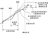
Even when carrying out the known image space Forecasting Methodology be applied to move object, expect that also SF is set as little value.Reason is following.Estimate following image space based on linear straight line, a plurality of image spaces of the object of the said linear straight line acquisition of passing over.In this case, the time interval of image space that obtains object is long more, and in other words, SF is more little, and the difference between following image space and the image space estimated based on a plurality of image spaces in past can be more little.With reference to Fig. 3 this point is described.
Focus detecting unit 204 has object's position and detects error when detecting practical object position (solid line of Fig. 3), thus, in Fig. 3, with respect to the physical location (solid line) of object, represent the object's position through focus detecting unit 204 detections with long dotted line.
Based on the object's position that detects, estimate at image space when the timing (in Fig. 3, being indicated as the dotted line of " discharging timing ") when all depressing release-push 210 and set SW2_ON.
Under the situation of SF little (in Fig. 3, being indicated as " long SI "); The detection error of the image space of being predicted (in Fig. 3 with dashed lines indication) is by average, thus with the object's position of practical object position and estimation between the corresponding error of difference little.
On the contrary; Under the situation of SF big (in Fig. 3, being indicated as " short SI "); The detection error of the image space (in Fig. 3 with short dash line (dotted line) indicate) of prediction is not average by satisfactorily, thus with the object's position of practical object position and estimation between the corresponding error of difference greater than the error under the little situation of SF.
Therefore, when execution was applied to move the known image space Forecasting Methodology of object, the expectation SF was set as little value.
In contrast; Under the situation of object near image pick-up device 201; Even when object move lentamente on the optical axis direction or image pick-up device 201 because shake when on optical axis direction, moving lentamente, the image planes distance also non-linearly changes with respect to the change of object distance.
As shown in Figure 8, during near the macroshot of image pick-up device 201, object distance is short at object, and the focal position often changes thus, and the speed of focal variation often changes or the direction of focal variation is often reversed.Therefore, the SF under continuous mode hour can not catch up with the variation of focal position or the change of focal variation speed for the estimation of object's position, and the physical location of AF lens 140 departs from object's position thus.As a result, focus alignment taking place takes.
Like this, under the situation of object, that is, taking under the big situation of multiplying power, can alleviate focus alignment through increasing SF near image pick-up device 201.
Based on this fact, in the present embodiment, the sampling period depends on shooting multiplying power β and changes.When taking multiplying power greater than reference shooting multiplying power (being equal to or greater than predetermined value), SF is increased.
When depending on, SF that kind as described above takes multiplying power β and when changing; Even taking under the situation that moves object with normal shooting distance and under the situation at macroshot, also can when reducing amount, take with the shooting of alleviation focus alignment.
Description turns back to the process flow diagram shown in Fig. 2.
In S1100, confirm the state in focus that in the position of AF lens 140, whether obtains this moment.When state is obtained in focus, handle entering into S1110.When state is not obtained in focus, handle entering into S1210.
When processing enters into S1110, confirm in S1110 whether release-push 210 is all depressed to set the SW2_ON state.When release-push 210 is in the SW2_ON state, handle entering into S1120.When release-push 210 during, handle turning back to S1010 not at the SW2_ON state.
In S1120, be used for taking preparation with turning over (flip up) on the principal reflection mirror 202.
In S1130; Based on the result who obtains through photometry among the S1020; Carry out a series of image pick-up operation, the opening of the operation of diaphragm (stop) (not shown) that for example in lens devices 101, is provided with and the shutter (not shown) that in image pick-up device 201, is provided with.These operations are known, so omit detailed description at this.
When handling when S1100 enters into S1210, camera cpu 209 reads the signal of two images with the SF of in S1070 or S1080, setting from photo-electric conversion element, and carries out correlation calculations obtaining image bias, thereby obtains amount.
In S1220, be based on the amount that obtains among the S1210, carry out servo-actuated (follow-up) control that is used to drive AF lens 140 with the SF of in S1070 or S1080, setting and calculate.
In S1230, will calculate the result who obtains through the control of the servo-actuated among the S1220 and export to the AF lens voltage driver 172 that is used to drive AF lens 140.Afterwards, processing turns back to S1020.In this case, AF lens 140 are moved predetermined amount.
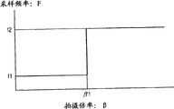
In the present embodiment, based on use 0.2 shooting multiplying power β as a reference, SF F is made as f1 or f2.In other words, based on taking multiplying power β SF F is made as any one in these two frequencies.Yet the present invention is not limited to this.
About the example shown in Fig. 4 A, when shooting multiplying power β was β 1 (β 1=0.2) under above-mentioned situation, SF F became f2 or becomes f1 from f2 from f1.Yet, shown in Fig. 4 B, be under the situation between β 1 (for example, β 1=0.2) and the β 2 (for example, β 2=0.5), even when SF F changes corresponding to the change of taking multiplying power continuously, also obtain identical effect in the shooting multiplying power.
(second embodiment)
Hereinafter, with reference to Fig. 5 automatic focus (AF) the adjusting gear drive controlling method in the second embodiment of the invention is described.
Fig. 5 shows the process flow diagram of operating process of the AF lens 140 of AF adjusting gear in the present embodiment.The AF adjustment operation of AF lens 140 hereinafter, is described.In this case, similar with first embodiment, set continuous mode for AF.
The processing of S2010 to S2050 is corresponding to the processing of the S1010 to S1050 described in first embodiment, and the descriptions thereof are omitted here thus.
In S2060, confirm to take multiplying power β and whether be equal to or greater than 0.2.When shooting multiplying power β is equal to or greater than 0.2, handle entering into S2070.When taking multiplying power β less than 0.2 the time, handle entering into S2080.
In S2070, the PREDICTIVE CONTROL of image space is set as " pass " under continuous mode.
On the other hand, in S2080, the PREDICTIVE CONTROL of image space is set as " opening " under continuous mode.
The ON/OFF that the PREDICTIVE CONTROL of image planes device is described below depends on the reason of taking multiplying power β and changing.
As shown in Figure 8, under the situation of macroshot, the focal position is because the variation of object distance and often changing, and focal variation speed often changes or the focal variation direction is often reversed.Therefore, there is the situation that is difficult to the driving target location of AF lens is made as the practical object distance according to higher precision.Like this, even when setting the driving target location of AF lens through the PREDICTIVE CONTROL under the continuous mode, the position of AF lens can be different from the position in focus of object during taking.
Therefore; In the PREDICTIVE CONTROL that stops during the macroshot under the continuous mode; Be recycled and reused for the focusing operation that the AF lens is moved to the position corresponding,, follow focal variation thus and take to suppress focus alignment up to setting SW2_ON among the described S2110 in the back with measured object distance.
In contrast; Taking under the little situation of multiplying power; That is, under the situation of object, also described in first embodiment away from image pick-up device 201; When owing to the relative change of slowly moving the object distance that cause of the image pick-up device that causes because of shake 201 on optical axis direction hour, remarkable change does not take place in image planes distances " b ".Yet; For example; When the object of distant location during, can estimate in a scope easily that because the change of the image planes distances " b " that the change of object distance " a " causes, this scope can not cause the focus alignment shooting because object distance is big with high-speed mobile.Thereby, to take under the little situation of multiplying power, known image space PREDICTIVE CONTROL is effective for suppressing the focus alignment shooting.
If whether be applied to the image position PREDICTIVE CONTROL depend on and take multiplying power β and change,, also can when focus alignment is taken suppressing even taking under the situation that moves object with normal shooting distance and under the situation at macroshot so.
Description turns back to the process flow diagram shown in Fig. 5.
The processing of S2100~S2130 and S2210~S2230 is omitted here thus and is described corresponding to S1100~S1130 described in first embodiment and the processing of S1210~S1230.
Fig. 6 is illustrated in the physical location of AF lens 140 under the situation of using the control method described in first and second embodiment concurrently and the comparison between the object's position.In other words; Result shown in Fig. 6 is equal to or greater than under 0.2 the situation taking multiplying power β; Not through PREDICTIVE CONTROL; But the image space through the object-based past is performed with the control that reduces amount and obtains, and the image space in the past of said object detects with SF f1.
As can be seen from Figure 6, when SF is set as PREDICTIVE CONTROL under f1 (40Hz) and the continuous mode when not being performed, the physical location of AF lens 140 is followed the change of object's position.
Thereby, can find out, can carry out wherein focus alignment shooting during the macroshot than receiving the shooting that suppresses of more under the regular situation more.In contrast, when taking multiplying power β less than 0.2 normal photographing, expectation SF F is set as f2 less than f1 to carry out PREDICTIVE CONTROL.
In a second embodiment, the PREDICTIVE CONTROL under the continuous mode is switched between " opening " state and " pass " state based on taking multiplying power β.Yet the present invention is not limited to this.
The process flow diagram of reference example such as Fig. 7 is described the modification example of second embodiment.
In Fig. 7, the difference of revising the example and second embodiment is: based on the processing of carrying out through the definite result who obtains who takes multiplying power β among the S2060.
In S2060, when shooting multiplying power β is equal to or greater than 0.2, handle entering into S2310.On the other hand, when taking multiplying power β less than 0.2 the time, handle entering into S2320.
In S2310, first forecast Control Algorithm is set as the PREDICTIVE CONTROL of image space under the continuous mode.Two image spaces of the object of first forecast Control Algorithm acquisition of for example being based on are over predicted from detection and are lighted the known method through the image space after the preset time.
On the other hand, in S2320, second forecast Control Algorithm is set as the PREDICTIVE CONTROL of image space under the continuous mode.Six image spaces of the object of second forecast Control Algorithm acquisition of for example being based on are over predicted from detection and are lighted the known method through the image space after the preset time.
It is following that the quantity of image space that is used for the past of PREDICTIVE CONTROL depends on the reason of taking multiplying power β and changing.
During macroshot, object distance is short, changes the image planes distance because of the influence of moving or shaking of object probably thus, thereby causes focus alignment to be taken.Being reversed in the short time period of the change of the translational speed of image space or its moving direction often takes place.Thereby, even when the image space information based on the multinomial past is estimated the image position, also be difficult to be estimated accurately the image position.Thereby, when based on more relevant with the operation that is used for current image space, be right after two image spaces before the SW2_ON state when carrying out PREDICTIVE CONTROL, the control of higher forecasting precision can be implemented.
In contrast, when taking multiplying power hour, just,, influence the change of the object distance of image planes distance and maybe be usually take place under the situation of variation significantly on the optical axis direction at interval sometime in the position of object when object during away from image pick-up device 201.Thereby, when the more past image space (for example, six points) with object is used as the PREDICTIVE CONTROL data, can be reduced by prediction image space and the actual error between the image space in focus.So, can suppress focus alignment takes.
In other words, when suitable Forecasting Methodology is employed based on shooting multiplying power β, even taking under the situation that moves object with normal shooting distance and under the situation at macroshot, also can when suppressing the focus alignment shooting, take.
Although described the present invention with reference to exemplary embodiment, should be appreciated that the present invention is not limited to disclosed exemplary embodiment.The scope of accompanying claims should be given the most wide in range explanation so that comprise all alter modes and equivalent configurations and function.
For example, in the above-described embodiments each, Interchangeable lens type single lens reflex type camera has been described.Yet the present invention can be applicable to other optical devices, the video camera and the electronic stills camera of for example wherein integrated lens and camera.
In each embodiment, the device (so-called numeric type image pick-up device) that uses the image pick-up element reference object has been described.Yet the present invention can be applicable to use the so-called silver halide film type image pick-up device of film photographic object.
0.2 shooting multiplying power β be used as and be used for confirming whether shooting is the value of macroshot.Yet, even when for example 0.3 or 0.5 shooting multiplying power β is used as determined value, also obtain identical effect.
Although described the present invention, should be appreciated that the present invention is not limited to disclosed exemplary embodiment with reference to exemplary embodiment.The scope of accompanying claims should be given the most wide in range explanation so that comprise all alter modes and equivalent configurations and function.
Claims (5)
1. image pick-up device comprises:
Multiplying power information acquisition unit is used to obtain comprise the information of the shooting multiplying power of photographing optical system;
Control module is used for said photographing optical system is carried out focus control; With
Detecting unit is used to detect amount, and the difference between the image space of the image pickup position of said amount and object and the said object that formed by said photographing optical system is corresponding,
Wherein, even after obtaining the state in focus of said photographing optical system through said focus control, if image pick-up operation is not begun, then said control module still repeats said focus control, and
Wherein, when said shooting multiplying power was equal to or greater than predetermined value, the value that said control module will be used to detect the SF of said amount was made as greater than in the value of said shooting multiplying power less than the SF under the situation of said predetermined value.
2. lens devices that can be installed to image pick-up device according to claim 1 removedly, it comprises said photographing optical system.
3. image pick-up device comprises:
Multiplying power information acquisition unit is used to obtain comprise the information of the shooting multiplying power of photographing optical system;
Control module is used for said photographing optical system is carried out focus control; With
Detecting unit is used to detect amount, and the difference between the image space of the image pickup position of said amount and object and the said object that formed by said photographing optical system is corresponding,
Wherein, Said control module is estimated the image space of following said object based on the image space of said object of past; Even and after obtaining the state in focus of said photographing optical system through said focus control, if image pick-up operation is not begun, then said control module still repeats said focus control; So that the image space of said object will reduce the amount of image space with respect to said object in future based on estimative future, and
Wherein, When said shooting multiplying power is equal to or greater than predetermined value; Said control module is set the quantity of data of image space of the said object of past of the image space that is used to estimate following said object, and said quantity is less than in the quantity of said shooting multiplying power less than the data of the image space of the said object of past under the situation of said predetermined value.
4. lens devices that can be installed on image pick-up device according to claim 3 removedly, it comprises said photographing optical system.
5. image pick-up device comprises:
Multiplying power information acquisition unit is used to obtain comprise the information of the shooting multiplying power of photographing optical system;
Control module is used for said photographing optical system is carried out focus control; With
Detecting unit is used to detect amount, and the difference between the image space of the image pickup position of said amount and object and the said object that formed by said photographing optical system is corresponding,
Wherein, When said shooting multiplying power is equal to or greater than predetermined value; Even after obtaining the state in focus of said photographing optical system through said focus control, if image pick-up operation is not begun, then said control module still repeats said focus control; So that under the situation of the image space of not estimating following said object, reduce amount with respect to the image space of said object of past, and
Wherein, When said shooting multiplying power during less than said predetermined value; Said control module is estimated the image space of following said object based on the image space of said object of past; Even and after obtaining the state in focus of said photographing optical system through said focus control; If image pick-up operation is not begun, then said control module still repeats said focus control, so as based on estimative future said object image space reduce the amount of image space with respect to said object in future.
Applications Claiming Priority (2)
| Application Number | Priority Date | Filing Date | Title |
|---|---|---|---|
| JP2009-157616 | 2009-07-02 | ||
| JP2009157616A JP5336952B2 (en) | 2009-07-02 | 2009-07-02 | Optical equipment |
Publications (2)
| Publication Number | Publication Date |
|---|---|
| CN101943840A CN101943840A (en) | 2011-01-12 |
| CN101943840B true CN101943840B (en) | 2012-03-07 |
Family
ID=43412723
Family Applications (1)
| Application Number | Title | Priority Date | Filing Date |
|---|---|---|---|
| CN2010102207018A Active CN101943840B (en) | 2009-07-02 | 2010-06-29 | Image pickup apparatus and lens device |
Country Status (3)
| Country | Link |
|---|---|
| US (1) | US8135269B2 (en) |
| JP (1) | JP5336952B2 (en) |
| CN (1) | CN101943840B (en) |
Families Citing this family (7)
| Publication number | Priority date | Publication date | Assignee | Title |
|---|---|---|---|---|
| JP5336952B2 (en) * | 2009-07-02 | 2013-11-06 | キヤノン株式会社 | Optical equipment |
| JP2011064988A (en) * | 2009-09-18 | 2011-03-31 | Canon Inc | Imaging device and lens device |
| CN102754011B (en) * | 2010-02-03 | 2015-08-05 | 株式会社尼康 | Finder and observational technique |
| JP5882593B2 (en) * | 2011-03-14 | 2016-03-09 | キヤノン株式会社 | Imaging device |
| US10834309B2 (en) * | 2017-11-16 | 2020-11-10 | Canon Kabushiki Kaisha | Lens control apparatus and control method for tracking moving object |
| JP7112863B2 (en) * | 2018-03-22 | 2022-08-04 | 株式会社ミツトヨ | Information processing device, information processing method, program, and image measuring device |
| CN108600638B (en) * | 2018-06-22 | 2020-08-04 | 中国计量大学 | Automatic focusing system and method for camera |
Family Cites Families (14)
| Publication number | Priority date | Publication date | Assignee | Title |
|---|---|---|---|---|
| US5243375A (en) * | 1987-05-21 | 1993-09-07 | Minolta Camera Kabushiki Kaisha | Automatic focus adjusting device for adjusting the focus of the main object to be photographed |
| JP2662650B2 (en) * | 1987-11-06 | 1997-10-15 | ミノルタ株式会社 | Automatic focusing device |
| JP2697133B2 (en) * | 1989-05-18 | 1998-01-14 | ミノルタ株式会社 | Auto focus camera |
| JP3103587B2 (en) * | 1990-04-25 | 2000-10-30 | オリンパス光学工業株式会社 | Automatic focusing device |
| JP3513950B2 (en) | 1993-12-14 | 2004-03-31 | 株式会社ニコン | Image stabilization camera |
| JP2757821B2 (en) * | 1995-05-12 | 1998-05-25 | ミノルタ株式会社 | Automatic focusing device |
| JPH0968644A (en) * | 1995-08-31 | 1997-03-11 | Nikon Corp | Automatic focusing device |
| JP2001021794A (en) | 1999-07-12 | 2001-01-26 | Canon Inc | Auto-focusing adjusting device, and optical instrument |
| JP3851027B2 (en) * | 1999-08-27 | 2006-11-29 | 株式会社リコー | Autofocus device and camera |
| KR100562404B1 (en) * | 2003-12-19 | 2006-03-17 | 삼성테크윈 주식회사 | Method of automatic focusing for camera wherein additional scanning is performed |
| US20060092314A1 (en) * | 2004-10-31 | 2006-05-04 | Silverstein D A | Autofocus using a filter with multiple apertures |
| JP4555255B2 (en) * | 2006-05-15 | 2010-09-29 | 株式会社リコー | Automatic focusing device, digital camera, portable information input device, focusing position detection method, and computer-readable recording medium |
| JP2010122497A (en) * | 2008-11-20 | 2010-06-03 | Canon Inc | Optical device incorporating automatic focusing function |
| JP5336952B2 (en) * | 2009-07-02 | 2013-11-06 | キヤノン株式会社 | Optical equipment |
-
2009
- 2009-07-02 JP JP2009157616A patent/JP5336952B2/en not_active Expired - Fee Related
-
2010
- 2010-06-11 US US12/814,165 patent/US8135269B2/en not_active Expired - Fee Related
- 2010-06-29 CN CN2010102207018A patent/CN101943840B/en active Active
Also Published As
| Publication number | Publication date |
|---|---|
| US8135269B2 (en) | 2012-03-13 |
| JP2011013460A (en) | 2011-01-20 |
| US20110002679A1 (en) | 2011-01-06 |
| JP5336952B2 (en) | 2013-11-06 |
| CN101943840A (en) | 2011-01-12 |
Similar Documents
| Publication | Publication Date | Title |
|---|---|---|
| CN101943840B (en) | Image pickup apparatus and lens device | |
| US7932950B2 (en) | Automatic focusing apparatus and image pickup apparatus | |
| EP1607792A2 (en) | Optical apparatus | |
| JP5007612B2 (en) | Focus adjustment device | |
| JP2597961B2 (en) | Automatic focusing device | |
| US8743267B2 (en) | Optical apparatus for calculating an object distance | |
| CN102694974A (en) | focus detection apparatus, method for controlling the same, and image capturing apparatus having a focus detection apparatus | |
| JP2013083843A (en) | Optical instrument, lens barrel, and automatic focus adjustment method | |
| JP2010008507A (en) | Camera | |
| US6128035A (en) | Anti-blur image pickup device | |
| JPH0862484A (en) | Focusing device | |
| US5634142A (en) | Camera having a vibration correction lens and a method for correcting image vibration | |
| JP2011107501A (en) | Focusing device and imaging apparatus | |
| JP2002131624A (en) | Multipoint automatic focusing camera | |
| JP2006065080A (en) | Imaging device | |
| JP2012042589A (en) | Image shake correction mechanism, lens barrel, and image sensor | |
| JP2002023041A (en) | Photographing distance measuring device, photographing lens, camera system and information arithmetic device for camera system | |
| JP4862297B2 (en) | Electronic camera and camera system | |
| JP2004170601A (en) | Optical device with image blur correcting function, interchangeable lens for cameras, and blur sensing device | |
| JP2018054698A (en) | Optical device, imaging apparatus and control method | |
| JP2001133678A (en) | Automatic multi-point focusing camera | |
| JPH05173219A (en) | Camera having jiggling correction function | |
| JP2016102979A (en) | Imaging device and control method of imaging device | |
| JPH0511312A (en) | Exposure controller for camera | |
| JP2020170144A (en) | Lens device and imaging apparatus having the same |
Legal Events
| Date | Code | Title | Description |
|---|---|---|---|
| C06 | Publication | ||
| PB01 | Publication | ||
| C10 | Entry into substantive examination | ||
| SE01 | Entry into force of request for substantive examination | ||
| C14 | Grant of patent or utility model | ||
| GR01 | Patent grant |