CN101933145B - Optoelectronic module and projection device comprising the optoelectronic module - Google Patents
Optoelectronic module and projection device comprising the optoelectronic module Download PDFInfo
- Publication number
- CN101933145B CN101933145B CN2009801038516A CN200980103851A CN101933145B CN 101933145 B CN101933145 B CN 101933145B CN 2009801038516 A CN2009801038516 A CN 2009801038516A CN 200980103851 A CN200980103851 A CN 200980103851A CN 101933145 B CN101933145 B CN 101933145B
- Authority
- CN
- China
- Prior art keywords
- filter
- radiation
- light
- optoelectronic module
- led
- Prior art date
- Legal status (The legal status is an assumption and is not a legal conclusion. Google has not performed a legal analysis and makes no representation as to the accuracy of the status listed.)
- Expired - Fee Related
Links
Images


Classifications
-
- H—ELECTRICITY
- H04—ELECTRIC COMMUNICATION TECHNIQUE
- H04N—PICTORIAL COMMUNICATION, e.g. TELEVISION
- H04N9/00—Details of colour television systems
- H04N9/12—Picture reproducers
- H04N9/31—Projection devices for colour picture display, e.g. using electronic spatial light modulators [ESLM]
- H04N9/3141—Constructional details thereof
- H04N9/315—Modulator illumination systems
- H04N9/3164—Modulator illumination systems using multiple light sources
-
- F—MECHANICAL ENGINEERING; LIGHTING; HEATING; WEAPONS; BLASTING
- F21—LIGHTING
- F21K—NON-ELECTRIC LIGHT SOURCES USING LUMINESCENCE; LIGHT SOURCES USING ELECTROCHEMILUMINESCENCE; LIGHT SOURCES USING CHARGES OF COMBUSTIBLE MATERIAL; LIGHT SOURCES USING SEMICONDUCTOR DEVICES AS LIGHT-GENERATING ELEMENTS; LIGHT SOURCES NOT OTHERWISE PROVIDED FOR
- F21K9/00—Light sources using semiconductor devices as light-generating elements, e.g. using light-emitting diodes [LED] or lasers
-
- H—ELECTRICITY
- H01—ELECTRIC ELEMENTS
- H01L—SEMICONDUCTOR DEVICES NOT COVERED BY CLASS H10
- H01L25/00—Assemblies consisting of a plurality of individual semiconductor or other solid state devices ; Multistep manufacturing processes thereof
- H01L25/03—Assemblies consisting of a plurality of individual semiconductor or other solid state devices ; Multistep manufacturing processes thereof all the devices being of a type provided for in the same subgroup of groups H01L27/00 - H01L33/00, or in a single subclass of H10K, H10N, e.g. assemblies of rectifier diodes
- H01L25/04—Assemblies consisting of a plurality of individual semiconductor or other solid state devices ; Multistep manufacturing processes thereof all the devices being of a type provided for in the same subgroup of groups H01L27/00 - H01L33/00, or in a single subclass of H10K, H10N, e.g. assemblies of rectifier diodes the devices not having separate containers
- H01L25/075—Assemblies consisting of a plurality of individual semiconductor or other solid state devices ; Multistep manufacturing processes thereof all the devices being of a type provided for in the same subgroup of groups H01L27/00 - H01L33/00, or in a single subclass of H10K, H10N, e.g. assemblies of rectifier diodes the devices not having separate containers the devices being of a type provided for in group H01L33/00
- H01L25/0753—Assemblies consisting of a plurality of individual semiconductor or other solid state devices ; Multistep manufacturing processes thereof all the devices being of a type provided for in the same subgroup of groups H01L27/00 - H01L33/00, or in a single subclass of H10K, H10N, e.g. assemblies of rectifier diodes the devices not having separate containers the devices being of a type provided for in group H01L33/00 the devices being arranged next to each other
-
- H—ELECTRICITY
- H01—ELECTRIC ELEMENTS
- H01L—SEMICONDUCTOR DEVICES NOT COVERED BY CLASS H10
- H01L2924/00—Indexing scheme for arrangements or methods for connecting or disconnecting semiconductor or solid-state bodies as covered by H01L24/00
- H01L2924/0001—Technical content checked by a classifier
- H01L2924/0002—Not covered by any one of groups H01L24/00, H01L24/00 and H01L2224/00
-
- H—ELECTRICITY
- H01—ELECTRIC ELEMENTS
- H01L—SEMICONDUCTOR DEVICES NOT COVERED BY CLASS H10
- H01L33/00—Semiconductor devices with at least one potential-jump barrier or surface barrier specially adapted for light emission; Processes or apparatus specially adapted for the manufacture or treatment thereof or of parts thereof; Details thereof
- H01L33/44—Semiconductor devices with at least one potential-jump barrier or surface barrier specially adapted for light emission; Processes or apparatus specially adapted for the manufacture or treatment thereof or of parts thereof; Details thereof characterised by the coatings, e.g. passivation layer or anti-reflective coating
-
- H—ELECTRICITY
- H01—ELECTRIC ELEMENTS
- H01L—SEMICONDUCTOR DEVICES NOT COVERED BY CLASS H10
- H01L33/00—Semiconductor devices with at least one potential-jump barrier or surface barrier specially adapted for light emission; Processes or apparatus specially adapted for the manufacture or treatment thereof or of parts thereof; Details thereof
- H01L33/48—Semiconductor devices with at least one potential-jump barrier or surface barrier specially adapted for light emission; Processes or apparatus specially adapted for the manufacture or treatment thereof or of parts thereof; Details thereof characterised by the semiconductor body packages
- H01L33/50—Wavelength conversion elements
Abstract
An optoelectronic module (11) for emitting monochromatic radiation in the visible wavelength region is provided. The module (11) comprises a plurality of light-emitting diode chips (1), which generate UV radiation. The UV radiation is converted by a wavelength converter (2) into light in the visible region, such as into green light. By using two selectively reflecting and transmitting filters (3, 4), the light decoupling of the module (11) is optimized. Said module (11) can be used as a light source in a projection device (12).
Description
Technical field
The present invention relates to optoelectronic module, relate to optoelectronic module that is used in the projection arrangement and the projection arrangement that comprises this optoelectronic module especially.
Background technology
For projection arrangement, need have the light source of high luminous power.The conventional light source that is used for projection arrangement is worked under high operating current and is produced significant used heat.Through using light-emitting diode chip for backlight unit, can avoid these disadvantageous effects as light source.Yet the luminous power of light-emitting diode chip for backlight unit is too low for multiple projection application at present.
In publication WO 2007/036214 A1 and US 2006/0057753 A1, opto-electronic device has been described.
Summary of the invention
The task that will solve is to propose a kind of opto-electronic device that has high luminous power.
What the inventor confirmed is that the radiation efficiency of light-emitting diode chip for backlight unit reduces under the situation of the wavelength increase of the radiation that is produced consumingly.For example, the radiation efficiency of the light-emitting diode chip for backlight unit of generation UV radiation is apparently higher than the efficient of the light-emitting diode chip for backlight unit that is created in the radiation in the green wavelength scope.Abbreviate these light-emitting diode chip for backlight unit as UV-LED or green LED below.
On the one hand, under the situation of low operating current I, for example under the situation of I=20mA the radiant power of UV-LED greater than the radiant power of green LED.On the other hand, when improving operating current, under the situation of green LED than reaching saturated in the power under the situation at UV-LED quickly.At this, linearity factor L
80/20Be tolerance to the big current efficiency of light-emitting diode.L
80/20Obtain the merchant of the luminous power P that when operating current is I=80mA and I=20mA, launches.In the ideal case, this factor is corresponding to the ratio of two operating currents and in value about 4.Under the situation of UV-LED, almost reach this ideal value, yet under the green LED situation, be significantly less than this ideal value.
The opto-electronic device of a kind of UV-LED of having and wavelength shifter has been proposed.The positive surface launching of LED is passed through in the UV radiation that is produced, and is mapped on the wavelength shifter.This wavelength shifter converts the UV radiation into visible light at least in part.
This device can be realized being transmitted in the monochromatic radiation in the visible range with high efficient.At this, when the wavelength of radiation was in the narrow scope in border, this radiation was called monochrome.The spectrum half breadth Δ λ of institute's radiation emitted preferably at 10nm in the scope of 100nm.
The emitted in ultraviolet radiation, be that the light-emitting diode chip for backlight unit of radiation of wavelength X≤420nm is for example based on indium gallium nitride (InGaN).This light-emitting diode chip for backlight unit may be embodied as thin-film light emitting diode chip.
Preferably, wavelength shifter converts the UV radiation into dominant wavelength λ
PeakGreen light in the scope of 490nm to 545nm.At this, dominant wavelength is following wavelength: the light intensity maximum of being launched is near this wavelength.
In another form of implementation of wavelength shifter, also can be created in the blue light in the wave-length coverage of 420nm to 490nm, perhaps be created in sodium yellow or red light in the wave-length coverage of 575nm to 750nm.
Wavelength shifter preferably comprises host material, and the particle of material for transformation of wave length is arranged in this host material.Be suitable for is for example Al of transparent material such as glass, quartz, sapphire, carborundum, transparent ceramic as host material
2O
3, diamond, silicones, acrylic acid ester, polyimides, Merlon, epoxy resin or these mixtures of material.Preferably, host material has high thermal conductivity, and can well the used heat that forms be distributed thus.Material with very high thermal conductivity for example is carborundum or diamond.
The particle of material for transformation of wave length preferably is evenly distributed in the host material as far as possible.
As material for transformation of wave length suitable be following material: its metal-doped by with from rare earths, for example garnet, alkaline earth sulfide, thiogallate (Thiogalate), aluminate, orthosilicate, Chlorosilicate (Chlorosilikate), alkaline-earth metal silicon nitride (Erdalkalisiliziumnitride), nitrogen oxide, aluminum oxynitride and silicon oxynitride.For example use YAG:Ce, it has the garnet luminescent materials YAG that cerium mixes.
In a form of implementation, host material is formed by transition material simultaneously, for example can use the YAG pottery.That is to say that wavelength shifter for example is embodied as ceramic conversion plate.In this case, the ceramic wavelength material is sintered to ceramic layer, and in this ceramic layer, the scattering of the radiation of passing can be regulated through the density of ceramic material and the pore size of the formation of gaseous inclusions in the ceramic material.
In addition, ceramic layer has the thermal conductivity higher than wavelength shifter, under the situation of this wavelength shifter, material for transformation of wave length is introduced in host material such as the silicones.In this way, can especially effectively heat be distributed from wavelength shifter.
Ceramic layer can be freely supported.So supporting mass that ceramic layer forms wavelength shifter simultaneously and is directed against wavelength shifter.Yet also possible is that ceramic layer is by fixing or deposit on supporting mass transparent, heat conduction such as sapphire or the carborundum like the extruding of thermal balance or these methods of laser deposition of pulsed.
In a preferred form of implementation of opto-electronic device, in light path, be provided with at least one filter, it has high transmission capacity to one of two kinds of emission types, and has high albedo to another emission types.
This is expressed in " the high transmission capacity " of optical element (for example filter) this and can representes hereinafter, incides at least 50% of radiation on the element and passes this element.Preferably, incide at least 75% of radiation on the element and pass this element, be preferably at least 90% especially.
This is expressed in " the high albedo " of optical element (for example filter) this and can representes hereinafter, incide radiation on the element at least 50% by this element reflects.Preferably, incide radiation on the element at least 75% by this element reflects, be preferably at least 90% especially.
If this filter optionally to the UV radiation be transmissive and be reflected in the radiation in the visible wavelength region, then it is called the UV filter.If this filter optionally to the only transmissive in the visible range and reflection UV radiation, then its with upperseat concept thus filter represent.If it is designed for the radiation of transmission in the narrow wave-length coverage in border, then it comes to explain more accurately with term green filter, blue filter, yellow filter or red filter according to wave-length coverage.
In a preferred form of implementation, the UV filter is arranged between UV-LED and wavelength shifter, radiation has high transmission capacity and has high albedo for the radiation in the limit of visible spectrum for UV for it.
If the light that the quilt that comes out from wavelength shifter is changed is mapped on this UV filter, then this light is to returning towards the direction of wavelength shifter and especially towards the direction reflection of the coupling-out structure of opto-electronic device.Thus, obtain the coupling delivery efficiency of the raising of device.Under the situation that does not have the UV filter, visible light can be absorbed in UV-LED, supporting mass or housing.
In another form of implementation, visible filter is between the coupling-out structure of wavelength shifter and UV-LED, and this visible filter has high transmission capacity and has high albedo to the UV radiation to the radiation in the visible wavelength region.
On the one hand, can by this visible filter regulate institute's wavelength of light emitted with and half breadth.For example, this filter is a transmissive to the green light in the wave-length coverage between the 490nm to 545nm only.Preferably, this filter has also prevented to appear outward for the nocuous UV radiation direction of human eye thus.On the other hand, through the not radiation in the desirable wave-length coverage that will launch of reflection, improved the conversion efficiency of device and improved institute's emitted power thus.Especially, the UV radiation do not changed by to back reflective in wavelength shifter and can convert visible light there to.
In a particularly advantageous form of implementation, this opto-electronic device has UV filter and visible filter.
For example, perhaps the two all is embodied as Bragg reflector (Bragg-Spiegel) to one of these filters.Bragg reflector is formed by having the high index of refraction alternately and the dielectric layer of low-refraction.For example, dielectric layer can comprise titanium dioxide (TiO
2), silicon dioxide (SiO
2), aluminium oxide (Al
2O
3), silicon nitride (SiN), tantalum pentoxide (Ta
2O
5) or hafnium oxide (HfO
2).
In a form of implementation, one of these filters or the two are arranged on the supporting mass.
In order to realize the optimal working mode of filter, the surface of supporting mass should be smooth as far as possible.
Preferably, supporting mass has high thermal conductivity, so and can realize the heat of distributing in UV-LED and in transducer, producing.For example, supporting mass comprises the carborundum that conducting power is about 200W/mK.Particularly advantageous is this supporting mass that is used for the UV filter because this supporting mass be in UV-LED around.Supporting mass can comprise one of material of being suitable for as the host material of wavelength shifter or multiple equally.
In a preferred form of implementation, one of these supporting masses or the two all are integrated in the wavelength shifter monolithic.That is to say, be connected to each other to supporting mass and wavelength shifter mechanical fixation.This connection can not without damage be unclamped.So supporting mass and wavelength shifter are made up by single type ground.Especially, wavelength shifter can be the supporting mass of filter simultaneously.This is provided with filter and wavelength shifter with can realizing saving especially the position.In addition, use at the same time under the situation of wavelength shifter as the supporting mass of filter, the manufacturing cost of this device is cheap especially.
Preferably, the UV filter is fixedly connected with UV-LED.
In a form of implementation, the UV filter is by connecting on the front of emitted radiation that material is fixed on UV-LED.Suitable connection material is transparent material such as silicon resin adhesive or mould material.
In another form of implementation, be integrated in the front of emitted radiation of UV-LED UV filter monolithic.The UV filter can be made by the method that also is used to make semiconductor body for this reason, and is perhaps compatible well with these methods.This method for example is sputter or epitaxial growth.Thus, the manufacturing process of filter is simplified technically.
In addition, proposed the optoelectronic module that is made up of above-mentioned device, this module comprises at least two UV-LED.At least one wavelength shifter is in the light path of the UV radiation that is produced.In a preferred form of implementation of opto-electronic device, at least one filter is set in light path, it has high transmission capacity for one of two kinds of emission types, and has high albedo for another emission types.
Preferably, UV-LED is arranged in the plane and has identical main radiation direction.For example, UV-LED is set to the grid of rule.Wavelength shifter preferably is embodied as smooth layer, and it is arranged on after the UV-LED on main radiation direction and covers this UV-LED.
Preferably, between UV-LED and wavelength shifter, be provided with one or more UV filters, and between the coupling output face of wavelength shifter and optoelectronic module, be provided with at least one visible filter.
Through the combination of a plurality of UV-LED, improved the brightness of light source.At this, can realize making module simply technical and with low costly and attach it in the housing, for example be installed in the projecting apparatus housing.
In a preferred form of implementation, all UV-LED are transmitted in the common wavelength shifter and in the common UV filter.The light of being changed is preferably through common visible filter.At this, these devices can directly be adjacent to each other and connection for example fixed to one another.Especially, filter can be integrated in the wavelength shifter monolithic.Common UV filter can be fixed on the UV-LED by connecting material, for example silicon resin adhesive or mould material.
In a preferred form of implementation, common UV filter and common visible filter are embodied as smooth layer respectively.At this, the UV filter is arranged on after the UV-LED on main radiation direction and as far as possible fully covers UV-LED.It is thus clear that filter is arranged on wavelength shifter on the main radiation direction of UV-LED after and equally as far as possible fully cover UV-LED.
Compare with independent devices, this common device can be technically more simply and cost make more cheaply.In addition, big common device has higher mechanical stability.It can be simply technical and cost be installed on the housing cheaplyer.
In a preferred form of implementation, common visible filter and wavelength shifter are at interval.In the gap, air gap or mould material can be arranged.By this gap, can distribute the heat that in UV-LED, forms better.
In another form of implementation, UV-LED has independently UV filter, independently wavelength shifter and independently visible filter respectively.The advantage that this device has is that light-emitting diode chip for backlight unit can be installed more neatly, for example also can be installed on the curved surface.Preferably, the gap that useful air or mould material are filled between device, they can realize good heat radiation.
The other form of implementation of optoelectronic module has for the common device of a plurality of UV-LED with for the combination of the self-existent device of some UV-LED.For example, a plurality of UV-LED can share a UV filter, and other UV-LED has independently UV filter.
For example in a form of implementation, UV filter and wavelength shifter can be implemented discretely, and visible filter is implemented as common filter.The UV filter can be integrated among the UV-LED by monolithic at this.In addition, they can directly be integrated into wherein with wavelength shifter adjacency and especially monolithic on the side that itself and UV-LED deviate from.In another form of implementation, they and wavelength shifter are at interval.It is thus clear that filter can be integrated into wherein with wavelength shifter adjacency, especially monolithic equally or be also with interval.The gap that exists can be filled with air or mould material.
Described optoelectronic module in its different forms of implementation for example can be used as light source and uses in projection arrangement.This optoelectronic module can have big light-emitting area through using abundant UV-LED.This module also produces high luminous flux under good big current efficiency situation as the opto-electronic device that has single UV-LED.For the heat radiation of optimum, can the gap be introduced in this module, fill with air or mould material in these gaps.In addition, this module can be integrated in the framework, can improve heat radiation equally thus.
According at least one form of implementation of optoelectronic module, be transmitted in monochrome, green radiation in the wave-length coverage of 490nm to 575nm by module.
According at least one form of implementation of optoelectronic module, be transmitted in by module monochrome in the wave-length coverage of 420nm to 490nm, blue radiation.
According at least one form of implementation of optoelectronic module, be transmitted in monochrome, yellow or red radiation in the wave-length coverage of 575nm to 750nm by module.
According at least one form of implementation of optoelectronic module, at least one light-emitting diode chip for backlight unit has independently wavelength shifter.
According at least one form of implementation of optoelectronic module, at least two, especially all light-emitting diode chip for backlight unit have common UV filter.
According at least one form of implementation of optoelectronic module, at least one light-emitting diode chip for backlight unit has independently UV filter.
According at least one form of implementation of optoelectronic module, at least two, especially all light-emitting diode chip for backlight unit have common visible filter.
According at least one form of implementation of optoelectronic module, at least one light-emitting diode chip for backlight unit has independently visible filter.
Description of drawings
Hereinafter by schematically and be not that the accompanying drawing that conforms with ratio is set forth the semiconductor chip that proposed and favourable expansion scheme thereof.Wherein:
Fig. 1 shows and the dominant wavelength λ of the light launched
PeakThe linearity factor L of relevant different LED
80/20,
Fig. 2 show to UV-LED and green LED, as the luminous power P that is launched of the function of operating current I,
Fig. 3 A show to the UV-LED that has wavelength shifter and to green LED, as the luminous flux phi of the function of operating current I,
Fig. 3 B show to the UV-LED that has wavelength shifter and to green LED, as the dominant wavelength λ of the function of operating current I
Peak,
Fig. 4 A has illustrated the layout of UV filter, wavelength shifter and green filter in cross section,
Fig. 4 B has illustrated UV filter, wavelength shifter that has supporting mass and the layout that has the green filter of supporting mass in cross section,
Fig. 5 has illustrated the UV filter to having transmission capacity and the albedo of light under the situation of different incidence angles α of different wave length λ in curve chart,
Fig. 6 A has illustrated the optoelectronic module that has common transducer, common UV filter and common green filter in cross section,
Fig. 6 B shows the vertical view according to the optoelectronic module of Fig. 6 A,
Fig. 7 A has illustrated in cross section and has had independently wavelength shifter, independently the UV filter and the optoelectronic module of green filter independently,
Fig. 7 B shows the vertical view according to the optoelectronic module of Fig. 7 A,
Fig. 8 A in cross section, illustrated have common wavelength shifter, UV filter and with the optoelectronic module of transducer common green filter at interval,
Fig. 8 B in cross section, illustrated have wavelength shifter independently, independently the UV filter and with the optoelectronic module of transducer common green filter at interval,
Fig. 9 A has illustrated in cross section and has had common wavelength shifter, monolithic and be integrated into independently UV filter and the optoelectronic module of common green filter among the UV-LED,
Fig. 9 B has illustrated the optoelectronic module according to Fig. 9 A in cross section, wherein filter on radiation direction respectively with wavelength shifter at interval,
Figure 10 A has illustrated the opto-electronic device that does not have filter in cross section,
Figure 10 B has illustrated the opto-electronic device that has the UV filter in cross section,
Figure 10 C has illustrated the opto-electronic device that has green filter in cross section,
Figure 10 D in curve chart, illustrated as the function of phosphorus concentration C, according to the radiation efficiency E of the device of Figure 10 A, 10B and 10C,
Figure 11 shows and has the oblique view of optoelectronic module as the projection arrangement of light source.
Embodiment
In the accompanying drawing of being drawn, wavelength shifter 2, UV filter 3 and visible filter 4 exist with different forms of implementation.If a plurality of light-emitting diode chip for backlight unit 1 are shared common wavelength shifter 2a or common filter 3a, 4a, then increase alphabetical a respectively to reference marker.If light-emitting diode chip for backlight unit 1 has independently wavelength shifter 2b or independently filter 3b, 4b, then increase alphabetical b.
Among the embodiment that describes in the accompanying drawing below, there be the green InGaN-LED and the UV-InGaN-LED of normal structure form.In addition, use green filter.Yet this should not be limited to InGaN-LED and produce green light.Or rather, can use LED similarly with other semiconductor layer sequences and other versions.In addition, institute's radiation emitted can have other wavelength, for example the radiation in blue, red or yellow wavelengths scope.
Different InGaN-LED to the normal structure form in Figure 1A has drawn the dominant wavelength λ about the light of being launched respectively
PeakLinearity factor L
80/20Measured value 100 through obtaining to each LED is drawn equalizer curve 101.
Linearity factor L
80/20Be to the tolerance of the big current efficiency of LED and be defined as the ratio of institute's emitted power under the situation of operating current I=80mA and I=20mA.In the ideal case, this factor corresponding to the ratio of two operating currents and thus should the value 4 near.
Here the LED that measures produces has the dominant wavelength λ in the scope of 400nm to 525nm
PeakLight.What in Fig. 1, can see is that towards the direction of bigger wavelength, big current efficiency obviously reduces.For example, under the wavelength situation in the scope of 400nm, also promptly to the purple radiation, L
80/20In 3.4 to 3.8 scope.Under the wavelength situation of 420nm, also promptly to blue radiation, L
80/20Be reduced to the value in 2.9 to 3.3 the scope.Under the wavelength situation in the scope of 520nm, also promptly to green radiation, L
80/20Below 2.4 value.
In Fig. 2, be directed against λ
PeakThe green InGaN-LED 102 of=525nm with have λ
PeakThe UV-InGaN-LED 103 of=400nm has drawn luminous power P operating current I, that launched (unit is mW) about 0mA≤I≤80mA.
The better internal efficiency that from Fig. 2, shows UV-LED 103 on the one hand.In the gamut of operating current, the luminous power of UV-LED 103 is on the luminous power of green LED 102.For example, when operating current was I=80mA, the luminous power of UV-LED 103 was 3 times of luminous power of green LED 102.In addition, Fig. 2 shows the obviously better big current efficiency of UV-LED 103.Luminous power slightly surpasses twice from I=20mA to I=80mA under the situation of green LED 102, and the luminous power of UV-LED 103 becomes 3 times.
In Fig. 3 A to the UV-LED (below be called transducer LED) with wavelength shifter 104 and to green LED 105 drawn about mA be unit operating current I, be the luminous flux φ of unit with the lumen.Luminous flux φ is the tolerance to the brightness of the light source of estimating by eye sensitivity.In order to calculate φ, power output and the eye sensitivity in this spectral region of LED in the spectral region of confirming multiplied each other, and quadrature about the overall optical spectral space subsequently.
In Fig. 3 B, having drawn about mA to the LED 104,105 according to Fig. 3 A is the dominant wavelength λ of the operating current I of unit
Peak
Under the situation of I ≈ 20mA, the light that is sent has λ for two LED 104,105
PeakThe dominant wavelength of ≈ 528nm.Under the situation of green LED 105, dominant wavelength is passed towards short wavelength's direction more under the situation that operating current improves.Yet under the situation of transducer LED 104, dominant wavelength only less reduces between the 350mA at 20mA.Under the situation of I=350mA, dominant wavelength λ
Peak≈ 526nm.
Fig. 3 A and 3B illustrate thus, and transducer LED 104 compares with green LED 105 about big current efficiency aspect and about wavelength passing aspect all has more favourable characteristic.
Fig. 4 A shows the layout possibility of wavelength shifter 2, UV filter 3 and green filter 4.Wavelength shifter 2 is at two filters 3, between 4.If should arrange and use in transducer LED that then UV-LED was on the side that deviates from wavelength shifter 2 of UV filter 3.
A kind of layout has been shown in Fig. 4 B, and it is corresponding to the layout at the wavelength shifter 2 shown in Fig. 4 A, UV filter 3 and green filter 4.Yet, be arranged on the supporting mass 51,52 at these two filters 3,4.Can also can only one of filter 3,4 be arranged on the supporting mass 51,52 as an alternative this.With shown layout is different here, filter 3,4 also can be arranged on the side that deviates from wavelength shifter 2 of supporting mass 51,52.Preferably, the supporting mass material has high thermal conductivity, and can distribute the heat of formation well thus.Especially advantageously, be arranged on the supporting mass 51 to major general UV filter, so that the heat that forms among the UV-LED is distributed.
In Fig. 5, drawn as transmission capacity T function, the UV filter and the albedo R that incide the wavelength X of the radiation on the UV filter.Because these values are relevant consumingly with the incidence angle that radiation is mapped on the UV filter, so T and the R to six kinds of different incidence angles has been shown in six curves.At this, curve 111,112,113,114,115 and 116 is corresponding to 0 ° of incidence angle, 15 °, 30 °, 45 °, 60 ° and 70 °.In the scope of 380nm≤λ≤420nm, for all incidence angles, transmission capacity is T ≈ 90%.For every other wavelength region may, for the transmission capacity of a plurality of incidence angles obviously at this below value.
Albedo R obtains being R=100%-T-A by the transmission capacity T under the current absorption A situation of filter.Because the absorption of measured here filter is insignificant, directly obtains so reflect R, and show by Fig. 5 equally by R=100%-T.For at the wavelength of 525nm in the scope between the 570nm, for nearly all incidence angle all with at least 45% reflection of the light of incident.
So current filter is optionally to green light, for example have high albedo to λ=525nm, and optionally to the UV radiation, for example have high transmission capacity to λ=400nm, and therefore be called the UV filter.
In Fig. 6 A, 6B, 7A, 7B, 8A, 8B, 9A and 9B, schematically shown various embodiment to optoelectronic module.Device shown in all has six UV-LED 1.One or more wavelength shifter 2a, 2b convert the UV radiation radiation of bigger wavelength into, convert green light at this.
Between each light-emitting diode chip for backlight unit 1 and each wavelength shifter 2a, 2b, at least one UV filter 3a, 3b are arranged, its for UV radiation be transmissive and the reflection green radiation.In a preferred form of implementation, this filter has according to the transmission capacity of Fig. 5 and albedo.If emission has the visible light of another wavelength, can use filter with another reflection characteristic.At least one green filter 4a, 4b are arranged on the side that deviates from light-emitting diode chip for backlight unit 1 of wavelength shifter 2a, 2b, its for green light be transmissive and reflection UV radiation.In another form of implementation, optoelectronic module can only comprise a kind of filter.
Fig. 6 A has illustrated a kind of optoelectronic module 11 in cross section, wherein all UV-LED 1 share common UV filter 3a, common green filter 4a and common wavelength shifter 2a.At this, device 3a, 4a and 2a are embodied as smooth layer, and they directly are adjacent to each other.UV filter 3a is by connecting on the front 10 of emitted radiation that material 7 is fixed on UV-LED 1, and wherein this connection material for example can be silicon resin adhesive or mould material.
Fig. 6 B shows the vertical view of this module 11.At this, can see six UV-LED 1 and common green filter 4a, this green filter almost completely covers UV-LED 1.
An embodiment of module 11 has been shown in cross section in Fig. 7 A, and wherein each UV-LED 1 has independently UV filter 3b, independently green filter 4b and wavelength shifter 2b independently.These elements are similar to Fig. 6 A and are embodied as smooth layer and directly are adjacent to each other.Independently UV filter 3b also is fixed on the UV-LED 1 by connecting material 7 at this.
Fig. 7 B shows the vertical view according to the module 11 of Fig. 7 A, wherein can see independently green filter 4b, and they cover UV-LED 1 except contact area.
An embodiment of module 11 has been shown in Fig. 8 A, and wherein all UV-LED 1 share common wavelength shifter 2a, common UV filter 3a and common green filter 4a.UV filter 3a is fixed on the UV-LED 1 by connecting material 7.Green filter 4a and wavelength shifter 2a are at interval.The gap 6 that exists for example is air gap or fills with mould material.
Fig. 8 B shows another embodiment of module 11, wherein shares common UV filter 4a like all UV-LED 1 among Fig. 8 A, and this UV filter and wavelength shifter 2b are at interval.Yet be different from Fig. 8 A, have independently UV filter 3b and independently wavelength shifter 2b at this UV-LED 1.
Fig. 9 A shows an embodiment of module 11, and it has common wavelength shifter 2a, common green filter 4a and UV filter 3b independently.Independently UV filter 3b and common green filter 4a distinguish directly and wavelength shifter 2a adjacency.Be different from all embodiment shown in so far, independently UV filter 3b monolithic is integrated among the UV-LED 1.
Another embodiment of module 11 has been shown in Fig. 9 B, and it is in the additional gap 6 between UV filter 3b and the wavelength shifter 2a and between green filter 4a and wavelength shifter 2a with the different of the layout shown in Fig. 9 A.These gaps 6 can comprise air or mould material.
Different opto-electronic devices has been shown in cross section in Figure 10 A, 10B and 10C, and its radiation efficiency E is calculated and in Figure 10 D, is drawn.
UV-LED 1 has been shown in Figure 10 A, and it for example has by being welded to connect 9 wavelength shifters that are applied on the auxiliary bearing body 18.Shown opto-electronic device does not have filter.In Figure 10 B, green filter 4 additionally is positioned on the side that deviates from UV-LED 1 of wavelength shifter 2.In Figure 10 C, alternatively between wavelength shifter 2 and UV-LED 1, UV filter 3 is arranged.
The radiation efficiency E of this device calculates according to the phosphorus concentration C in the corresponding wavelength shifter 2.
In Figure 10 D, be that the percentage (%) that the phosphorus concentration C of unit has drawn with shows maximum radiation efficiency is the radiation efficiency of being calculated of the green light 22,23,24 of unit about percentage (%) with Cmax.For layout, drawn radiation efficiency in addition to the UV radiation of not changed 21 according to Figure 10 A.
In the layout shown in Figure 10 A, under the situation that is (verschwindend) phosphorus concentration C of zero, do not have transmitting green light, and radiation efficiency 22 is about 0% according to expection.Relative therewith, about 45% of the UV radiation 21 that in UV-LED 1, produces is coupled output.Radiation efficiency E for UV radiation 21 reduces under the situation that phosphorus concentration increases, and under the situation of C=90%, is almost 0%.Relative therewith, for green glow 22, E just raises under the situation that phosphorus concentration increases, and is issued to its maximum E ≈ 31% in the situation of C=50%, and under the situation that C further increases, slowly reduces.The reduction of radiation efficiency 22 can be owing to the absorption in wavelength shifter and led chip.Under the situation of C=90%, radiation efficiency 22 is E ≈ 20%.
Through using green filter 4, improved the radiation efficiency of green glow 24 according to Figure 10 B.Reason is, green filter is with the part of UV radiation again in the reflected back wavelength transducer 2.At this, it can be converted into green glow again.
Figure 10 D also shows the radiation efficiency of green glow 23 under the situation that has UV filter 3 according to Figure 10 C.Radiation efficiency 23 is apparently higher than in the radiation efficiency 24 that exists under the situation of green filter.In the scope of 10% observed≤C≤70%, under the situation that concentration C increases, radiation efficiency 23 increase and for the situation of C=70% about the value of E ≈ 55%.This owing to, so green light by the UV filter to back reflective and reduced the absorption in UV-LED.
In a word, be obviously to have improved radiation efficiency 24,23 to green glow through using green filter 4 and UV filter 3 by what obviously draw among Figure 10 D.Do not have near the maximum of radiation efficiency 22 in the scope of E ≈ 30% of device of filter, and be issued to the maximum of E ≈ 35%, and be issued in the situation of UV filter 3 and obviously surpass 50% maximum in the situation of green filter 4.Can be contemplated that radiation efficiency is improved once more under the situation of using green filter 4 and UV filter 3 at the same time.
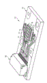
Figure 11 shows projection arrangement 12, wherein uses optoelectronic module 11 to be used to produce light.Optoelectronic module 11 has six UV-LED 1, and device UV filter 3, wavelength shifter 2 and according to the green filter in the form of implementation of Fig. 6 A, 6B, 7A, 7B, 8A, 8B, 9A or 9B 4.Optoelectronic module 11 is surrounded by framework 17, and this framework can distribute the heat that forms well.This framework is arranged on the auxiliary bearing body 18, and this auxiliary bearing body is positioned at again on the supporting mass 13.On this supporting mass 13, be applied with circuit board 14, the printed conductor 15 that is used for electrically contacting optoelectronic module 11 is introduced into this circuit board.Printed conductor 15 links to each other with plug 16, and this plug can be electrically connected.
The present invention is not confined to this through the description by embodiment, but comprises the new arbitrarily characteristic and the combination in any of characteristic.This especially is included in the combination in any of the characteristic in the claim, even this characteristic perhaps should not explained in claim or embodiment clearly in combination itself.
Present patent application requires the priority of German patent application DE 102008006974.4 and DE 102008017071.2, and its disclosure is incorporated into this by reference.
Claims (17)
1. optoelectronic module has:
-a plurality of light-emitting diode chip for backlight unit (1), it produces the UV radiation,
-at least one wavelength shifter (2), it is arranged on light-emitting diode chip for backlight unit (1) and converts the radiation in the visible wavelength region at least in part into afterwards and with the UV radiation on radiation direction, and
-at least one filter (3,4), it has high transmission capacity for one of two kinds of emission types, and has high albedo for another emission types.
2. optoelectronic module according to claim 1; Has UV filter (3); This UV filter is positioned between wavelength shifter (2) and the light-emitting diode chip for backlight unit (1), and radiation has high transmission capacity for UV, and has high albedo for the radiation in the visible wavelength region.
3. optoelectronic module according to claim 1; Has visible filter (4); Should on radiation direction, be arranged on wavelength shifter (2) afterwards by visible filter, and have high transmission capacity, and radiation has high albedo for UV for the radiation in the visible wavelength region.
4. according to each the described optoelectronic module in the claim 1 to 3, wherein at least one filter (3,4) is arranged on the transparent supporting mass of radiation (51,52), and this supporting mass has high thermal conductivity.
5. according to each the described optoelectronic module in the claim 1 to 3, wherein at least one filter (3,4) is arranged on the transparent supporting mass (51,52), and this supporting mass has high thermal conductivity.
6. optoelectronic module according to claim 4, wherein wavelength shifter (2) is contained in the supporting mass (51,52) of radiation transmissive.
7. optoelectronic module according to claim 5, wherein wavelength shifter (2) is contained in the transparent supporting mass (51,52).
8. according to each the described optoelectronic module in the claim 1 to 3, wherein at least two light-emitting diode chip for backlight unit (1) have common wavelength shifter (2a).
9. according to each the described optoelectronic module in the claim 1 to 3, wherein all light-emitting diode chip for backlight unit (1) have common wavelength shifter (2a).
10. according to each the described optoelectronic module in the claim 1 to 3, wherein filter (3,4) on radiation direction with wavelength shifter (2) at interval.
11. according to each the described optoelectronic module in the claim 1 to 3, its air or mould material are positioned between filter (3,4) and the wavelength shifter (2).
12. optoelectronic module according to claim 2, wherein UV filter (3) monolithic is integrated in the light-emitting diode chip for backlight unit (1).
13. optoelectronic module according to claim 2, wherein UV filter (3) on radiation direction with light-emitting diode chip for backlight unit (1) at interval.
14. optoelectronic module according to claim 2, wherein silicon resin adhesive or mould material are positioned between UV filter (3) and the light-emitting diode chip for backlight unit (1).
15. each the described optoelectronic module according in the claim 1 to 3 has at least three light-emitting diode chip for backlight unit (1), wherein:
-each light-emitting diode chip for backlight unit (1) is related one to one with the UV filter (3) of transmission UV radiation; And directly be provided with said UV filter (3) afterwards at each light-emitting diode chip for backlight unit (1); Wherein each light-emitting diode chip for backlight unit (1) is integrated with its UV filter (3) monolithic
-after the layout of light-emitting diode chip for backlight unit (1) and UV filter (3) formation, be provided with just what a wavelength shifter (2), and
-be provided with just what a visible filter (4) afterwards at wavelength shifter (2).
16. a projection arrangement wherein will be designed to light source according to each the described optoelectronic module in the claim 1 to 15.
17. projection arrangement according to claim 16, wherein optoelectronic module is surrounded by the framework of heat conduction (17).
Applications Claiming Priority (5)
| Application Number | Priority Date | Filing Date | Title |
|---|---|---|---|
| DE102008006974 | 2008-01-31 | ||
| DE102008006974.4 | 2008-01-31 | ||
| DE102008017071.2 | 2008-04-03 | ||
| DE102008017071A DE102008017071A1 (en) | 2008-01-31 | 2008-04-03 | Optoelectronic module and projection device with the optoelectronic module |
| PCT/DE2009/000103 WO2009094994A1 (en) | 2008-01-31 | 2009-01-26 | Optoelectronic module and projection device comprising the optoelectronic module |
Publications (2)
| Publication Number | Publication Date |
|---|---|
| CN101933145A CN101933145A (en) | 2010-12-29 |
| CN101933145B true CN101933145B (en) | 2012-11-28 |
Family
ID=40822256
Family Applications (1)
| Application Number | Title | Priority Date | Filing Date |
|---|---|---|---|
| CN2009801038516A Expired - Fee Related CN101933145B (en) | 2008-01-31 | 2009-01-26 | Optoelectronic module and projection device comprising the optoelectronic module |
Country Status (7)
| Country | Link |
|---|---|
| US (1) | US8585246B2 (en) |
| EP (1) | EP2245668B1 (en) |
| JP (1) | JP2011511447A (en) |
| KR (1) | KR101540828B1 (en) |
| CN (1) | CN101933145B (en) |
| DE (1) | DE102008017071A1 (en) |
| WO (1) | WO2009094994A1 (en) |
Families Citing this family (16)
| Publication number | Priority date | Publication date | Assignee | Title |
|---|---|---|---|---|
| JP2010108965A (en) * | 2008-10-28 | 2010-05-13 | Nippon Electric Glass Co Ltd | Wavelength conversion member |
| EP2555260A1 (en) * | 2010-03-30 | 2013-02-06 | Mitsubishi Chemical Corporation | Light-emitting device |
| WO2012014360A1 (en) * | 2010-07-26 | 2012-02-02 | 株式会社小糸製作所 | Light-emitting module |
| DE102011102032A1 (en) * | 2011-05-19 | 2012-11-22 | Osram Opto Semiconductors Gmbh | Optoelectronic semiconductor module and display with a plurality of such modules |
| DE102012005654B4 (en) | 2011-10-25 | 2021-03-04 | Schott Ag | Optical converter for high luminance levels |
| CN104991407B (en) * | 2011-11-10 | 2017-02-01 | 深圳市光峰光电技术有限公司 | Light source system, lighting device and projection device |
| JP6535598B2 (en) | 2012-11-07 | 2019-06-26 | ルミレッズ ホールディング ベーフェー | Light emitting device including filter and protective layer |
| DE102013214896B4 (en) * | 2013-07-30 | 2021-09-09 | OSRAM Opto Semiconductors Gesellschaft mit beschränkter Haftung | Method for producing a converter element and an optoelectronic component, converter element and optoelectronic component |
| JP6476545B2 (en) * | 2014-01-22 | 2019-03-06 | 日本電気硝子株式会社 | Fluorescent wheel for projector and light emitting device for projector |
| DE102015104237B4 (en) | 2015-03-20 | 2022-10-06 | OSRAM Opto Semiconductors Gesellschaft mit beschränkter Haftung | optoelectronic component |
| DE102015105893A1 (en) * | 2015-04-17 | 2016-10-20 | Osram Gmbh | Optoelectronic component and method for producing an optoelectronic component |
| DE102015105897A1 (en) * | 2015-04-17 | 2016-10-20 | Osram Gmbh | Optoelectronic component |
| DE102015105896B4 (en) * | 2015-04-17 | 2023-03-09 | OSRAM Opto Semiconductors Gesellschaft mit beschränkter Haftung | Optoelectronic component and method for producing an optoelectronic component |
| JP2019032563A (en) * | 2018-11-15 | 2019-02-28 | シャープ株式会社 | Light-emitting device and illumination device |
| KR102221426B1 (en) * | 2019-07-02 | 2021-03-02 | 셀로코아이엔티 주식회사 | Light Emitting Diode Display Device And Method Of Fabricating The Same |
| WO2024049582A1 (en) * | 2022-08-31 | 2024-03-07 | Lumileds Llc | Devices and methods preventing degradation of light emitting structures |
Citations (2)
| Publication number | Priority date | Publication date | Assignee | Title |
|---|---|---|---|---|
| JP2004219446A (en) * | 2003-01-09 | 2004-08-05 | Nitto Denko Corp | Manufacturing method of optical waveguide |
| JP2005322857A (en) * | 2004-05-11 | 2005-11-17 | Nippon Telegr & Teleph Corp <Ntt> | Optical resonator and method for manufacturing same |
Family Cites Families (27)
| Publication number | Priority date | Publication date | Assignee | Title |
|---|---|---|---|---|
| US5813752A (en) * | 1997-05-27 | 1998-09-29 | Philips Electronics North America Corporation | UV/blue LED-phosphor device with short wave pass, long wave pass band pass and peroit filters |
| US5813753A (en) * | 1997-05-27 | 1998-09-29 | Philips Electronics North America Corporation | UV/blue led-phosphor device with efficient conversion of UV/blues light to visible light |
| JPH11145519A (en) * | 1997-09-02 | 1999-05-28 | Toshiba Corp | Semiconductor light-emitting element, semiconductor light-emitting device, and image-display device |
| KR20040102054A (en) | 2002-03-29 | 2004-12-03 | 파이오니아 가부시키가이샤 | Organic electroluminescence display panel |
| GB0210203D0 (en) | 2002-05-03 | 2002-06-12 | Elam T Ltd | Electroluminescent devices |
| CN1656852A (en) | 2002-05-23 | 2005-08-17 | 富士电机控股株式会社 | Organic EL display |
| JP2004031843A (en) * | 2002-06-28 | 2004-01-29 | Kyocera Corp | Light-emitting diode |
| DE60330023D1 (en) * | 2002-08-30 | 2009-12-24 | Lumination Llc | HISTORIZED LED WITH IMPROVED EFFICIENCY |
| US7036946B1 (en) * | 2002-09-13 | 2006-05-02 | Rockwell Collins, Inc. | LCD backlight with UV light-emitting diodes and planar reactive element |
| WO2004068603A2 (en) * | 2003-01-27 | 2004-08-12 | 3M Innovative Properties Company | Phosphor based light source component and method of making |
| US7118438B2 (en) * | 2003-01-27 | 2006-10-10 | 3M Innovative Properties Company | Methods of making phosphor based light sources having an interference reflector |
| JP3865245B2 (en) | 2003-03-12 | 2007-01-10 | 富士電機ホールディングス株式会社 | Manufacturing method and manufacturing apparatus for organic EL display |
| US6994453B2 (en) * | 2003-03-21 | 2006-02-07 | Blanchard Randall D | Illumination device having a dichroic mirror |
| CN100472823C (en) * | 2003-10-15 | 2009-03-25 | 日亚化学工业株式会社 | Light-emitting device |
| KR20060113734A (en) | 2003-11-18 | 2006-11-02 | 쓰리엠 이노베이티브 프로퍼티즈 컴파니 | Electroluminescent devices and methods of making electroluminescent devices including a color conversion element |
| JP4317478B2 (en) * | 2004-03-31 | 2009-08-19 | 三菱化学株式会社 | Phosphor-type light emitting device and endoscope device using the same as an illumination source |
| WO2005099311A1 (en) | 2004-04-05 | 2005-10-20 | Idemitsu Kosan Co., Ltd. | Organic electroluminescence display device |
| TWI243625B (en) | 2004-05-04 | 2005-11-11 | Toppoly Optoelectronics Corp | Organic light-emitting display structure |
| US7070300B2 (en) * | 2004-06-04 | 2006-07-04 | Philips Lumileds Lighting Company, Llc | Remote wavelength conversion in an illumination device |
| US7256057B2 (en) | 2004-09-11 | 2007-08-14 | 3M Innovative Properties Company | Methods for producing phosphor based light sources |
| DE102005062514A1 (en) * | 2005-09-28 | 2007-03-29 | Osram Opto Semiconductors Gmbh | Multi-purpose light emitting diode incorporates selective wavelength trap |
| US7543959B2 (en) * | 2005-10-11 | 2009-06-09 | Philips Lumiled Lighting Company, Llc | Illumination system with optical concentrator and wavelength converting element |
| JP2007164123A (en) | 2005-11-15 | 2007-06-28 | Fuji Electric Holdings Co Ltd | Color filter with color conversion function, organic el display and producing method thereof |
| EP2057693A1 (en) * | 2006-08-29 | 2009-05-13 | Osram-Sylvania Inc. | Enhanced emission from phosphor-converted leds using interferometric filters |
| US8118441B2 (en) * | 2007-04-16 | 2012-02-21 | Goodrich Lighting Systems Gmbh | Color-variable LED light, particularly for lighting the interior of vehicles |
| DE102007041133A1 (en) | 2007-08-30 | 2009-03-05 | Osram Opto Semiconductors Gmbh | Housing with a housing lower part, as well as methods for emitting electromagnetic radiation |
| US7934862B2 (en) * | 2007-09-24 | 2011-05-03 | Munisamy Anandan | UV based color pixel backlight for liquid crystal display |
-
2008
- 2008-04-03 DE DE102008017071A patent/DE102008017071A1/en not_active Withdrawn
-
2009
- 2009-01-26 CN CN2009801038516A patent/CN101933145B/en not_active Expired - Fee Related
- 2009-01-26 JP JP2010544579A patent/JP2011511447A/en active Pending
- 2009-01-26 WO PCT/DE2009/000103 patent/WO2009094994A1/en active Application Filing
- 2009-01-26 US US12/863,717 patent/US8585246B2/en active Active
- 2009-01-26 KR KR1020107019148A patent/KR101540828B1/en active IP Right Grant
- 2009-01-26 EP EP09705404.3A patent/EP2245668B1/en active Active
Patent Citations (2)
| Publication number | Priority date | Publication date | Assignee | Title |
|---|---|---|---|---|
| JP2004219446A (en) * | 2003-01-09 | 2004-08-05 | Nitto Denko Corp | Manufacturing method of optical waveguide |
| JP2005322857A (en) * | 2004-05-11 | 2005-11-17 | Nippon Telegr & Teleph Corp <Ntt> | Optical resonator and method for manufacturing same |
Also Published As
| Publication number | Publication date |
|---|---|
| US20110019411A1 (en) | 2011-01-27 |
| EP2245668A1 (en) | 2010-11-03 |
| WO2009094994A1 (en) | 2009-08-06 |
| US8585246B2 (en) | 2013-11-19 |
| DE102008017071A1 (en) | 2009-08-06 |
| KR101540828B1 (en) | 2015-07-30 |
| CN101933145A (en) | 2010-12-29 |
| KR20100109561A (en) | 2010-10-08 |
| EP2245668B1 (en) | 2020-07-15 |
| JP2011511447A (en) | 2011-04-07 |
Similar Documents
| Publication | Publication Date | Title |
|---|---|---|
| CN101933145B (en) | Optoelectronic module and projection device comprising the optoelectronic module | |
| US7543959B2 (en) | Illumination system with optical concentrator and wavelength converting element | |
| EP3008380B1 (en) | Light emitting device | |
| EP3060955B1 (en) | Light emitting device | |
| US9121576B2 (en) | Light wavelength conversion unit | |
| JP5521325B2 (en) | Light emitting device and manufacturing method thereof | |
| US8189123B2 (en) | Projection apparatus | |
| CN102217065B (en) | Optoelectronic component | |
| US10386559B2 (en) | Light emitting device comprising wavelength converter | |
| US9772072B2 (en) | Illumination apparatus | |
| EP2064489B1 (en) | Brightness enhancement method and apparatus of light emitting diodes | |
| TW200923244A (en) | Semiconductor source of light with a source of primary rays and a luminescence conversion element | |
| KR20100091992A (en) | Light-emitting device and its manufacturing method | |
| US7714335B2 (en) | Light-emitting device with inorganic housing | |
| JP5967269B2 (en) | Light emitting device | |
| CN106449948B (en) | A kind of white light LEDs and its backlight module | |
| KR20190010478A (en) | Light-emitting device, integrated light-emitting device and light-emitting module | |
| JP2011134829A (en) | Light emitting device | |
| TW200947757A (en) | Lighting device | |
| US20220174795A1 (en) | System and method for providing color light sources in proximity to predetermined wavelength conversion structures | |
| CN106415836A (en) | Semiconductor component and illumination device | |
| US20160079490A1 (en) | Light emitting device comprising wavelength converter | |
| JP2019024071A (en) | Light-emitting device, integrated light-emitting device and light-emitting module | |
| JP2005109289A (en) | Light-emitting device | |
| JP2009070892A (en) | Led light source |
Legal Events
| Date | Code | Title | Description |
|---|---|---|---|
| C06 | Publication | ||
| PB01 | Publication | ||
| C10 | Entry into substantive examination | ||
| SE01 | Entry into force of request for substantive examination | ||
| C14 | Grant of patent or utility model | ||
| GR01 | Patent grant | ||
| CF01 | Termination of patent right due to non-payment of annual fee | ||
| CF01 | Termination of patent right due to non-payment of annual fee |
Granted publication date: 20121128 Termination date: 20220126 |