CN101884520B - Dishwasher - Google Patents
Dishwasher Download PDFInfo
- Publication number
- CN101884520B CN101884520B CN2010102315686A CN201010231568A CN101884520B CN 101884520 B CN101884520 B CN 101884520B CN 2010102315686 A CN2010102315686 A CN 2010102315686A CN 201010231568 A CN201010231568 A CN 201010231568A CN 101884520 B CN101884520 B CN 101884520B
- Authority
- CN
- China
- Prior art keywords
- washings
- pond
- filter
- dish
- washing machine
- Prior art date
- Legal status (The legal status is an assumption and is not a legal conclusion. Google has not performed a legal analysis and makes no representation as to the accuracy of the status listed.)
- Expired - Fee Related
Links
Images


Classifications
-
- A—HUMAN NECESSITIES
- A47—FURNITURE; DOMESTIC ARTICLES OR APPLIANCES; COFFEE MILLS; SPICE MILLS; SUCTION CLEANERS IN GENERAL
- A47L—DOMESTIC WASHING OR CLEANING; SUCTION CLEANERS IN GENERAL
- A47L15/00—Washing or rinsing machines for crockery or tableware
- A47L15/42—Details
- A47L15/4202—Water filter means or strainers
- A47L15/4204—Flat filters
-
- A—HUMAN NECESSITIES
- A47—FURNITURE; DOMESTIC ARTICLES OR APPLIANCES; COFFEE MILLS; SPICE MILLS; SUCTION CLEANERS IN GENERAL
- A47L—DOMESTIC WASHING OR CLEANING; SUCTION CLEANERS IN GENERAL
- A47L15/00—Washing or rinsing machines for crockery or tableware
- A47L15/42—Details
- A47L15/4214—Water supply, recirculation or discharge arrangements; Devices therefor
- A47L15/4225—Arrangements or adaption of recirculation or discharge pumps
- A47L15/4227—Arrangements or adaption of recirculation or discharge pumps with macerator arrangements for chopping entrained food particles
Abstract
The present invention relates to a dishwasher. In more detail, the present invention provides a dishwasher including a sump housing (100) for holding washing water, a washing water pumping unit (200) for pumping the washing water, a drain chamber (300) for receiving the washing water pumped thus, a soil chamber (421) for receiving the washing water through the drain chamber (300), a guide assembly (400) for guiding the washing water pumped thus to be provided to the soil chamber (421) via the drain chamber (300), and a sump cover (500) covered on an upper surface of the sump housing (100) for filtering the washing water overflowed from the soil chamber (421 ), thereby filtering the washing water effectively, and improving recovery ratio of the washing water to reduce consumption of the washing water and power.
Description
The application is the dividing an application that be on September 15th, 2005 and denomination of invention the applying date for the Chinese patent application No.200580013955.X of " dish-washing machine ".
Technical field
The present invention relates to dish-washing machine, more particularly, relate to a kind of effectively filtration washing water and can improve the dish-washing machine of the rate of recovery, minimizing washings and the energy consumption of washings.
Background technology
Dish-washing machine is sprayed onto washing agent and washings on the tableware, with automatic cleaning tableware.
Dish-washing machine is provided with at least one and is in the support that is used to place tableware in the basin, the pond that is used to keep washings, reaches the spray unit that at least one is used for spraying to tableware washings.
In the correlation technique of dish-washing machine, washings are pumped to spray unit from the pond, flow to spray arm along washing pipe, and spray to tableware.
The washings that washed tableware are recycled to the pond, and are fed to spray unit once more, to be sprayed onto on the tableware.
The use repeatedly of this washings will cause that foreign matter progressively increases in the washings.
Therefore, the scourability variation, and foreign matter blocks the filter at place, pond easily.If filter gets clogged, filter will be subjected to excessive pressure, cause filter impaired.
Summary of the invention
Technical problem
The object of the present invention is to provide a kind of dish-washing machine of new structure, its can use repeatedly swimmingly washings, swimmingly from washings, remove foreign matter, and can improve the organic efficiency of washings.
Technical scheme
Purpose of the present invention can realize that this dish-washing machine comprises by a kind of like this dish-washing machine is provided: the pond housing (sump housing) that is used to preserve washings; The washings water pump unit that is used for the pumping washings; Be used to receive drip chamber by the washings of pumping like this; Be used to receive soil chamber by the washings of described drip chamber; Be used to guide and be pumped by described drip chamber and so offer the directing assembly of the washings of described soil chamber; And cover the upper surface of described pond housing so that filter the pond cover of the washings that overflow from described soil chamber.
This dish-washing machine comprises the upper shell of pond housing upside, a plurality of sprue, reaches the lower house in the upper shell bottom, upper shell has the sampling runner, the washings that a plurality of sprues are used for not being provided for the sampling runner direct at least one spray arm, and lower house has soil chamber and the impeller bearing part that is formed on wherein.
Dish-washing machine also comprises the tube connector that is connected between soil chamber and the drip chamber, one end of sampling runner is inserted into tube connector, its other end is connected to the outlet side of described impeller bearing part, and has the connection runner between the outer periphery surface of a described end of tube connector inner rim and sampling runner.
The present invention on the other hand, the dish-washing machine that provides comprises the pond cover that is used to keep the pond housing of washings and is covered in pond housing upper surface, this pond cover has a plurality of being used for from the through hole of pond housing discharging washings and the recovery holes that a plurality of washings that are used for being discharged by through hole are recovered to the pond housing.
Through hole is formed at the inboard of pond cover, and recovery holes is formed in the exterior section of pond cover.
Pond cover has downward-sloping upper surface, and it is more and more downward-sloping to the part that is formed with recovery holes from the part that is formed with through hole, and preferably, also in each through hole filter member is set.Filter member comprises first filter and second filter, and each filter has a plurality of opening of sieves, and wherein, the opening of sieve of second filter is greater than the opening of sieve of first filter.
In still another aspect of the invention, dish-washing machine comprises the pond housing that is used to preserve washings; Have washing motor and impeller, be used for the washings water pump unit of pumping washings; Be used to receive drip chamber by the washings of pumping like this; Be in the drip chamber top, be used to receive soil chamber by the washings of drip chamber; And be in washing motor the axle on filter screen, it is used for filtering foreign matter from the washings that flow through this filter screen.
Filter screen has the plate of through hole that is used for by the axle of washing motor by comprising, and a plurality of hole that is used for by washings, and preferred with colluding the bottom that described filter screen is fixed on the pond housing.
In another aspect of the present invention, dish-washing machine comprises the pond housing that is used to preserve washings; The washings water pump unit that is used for the pumping washings; Be used to receive the drip chamber by the washings of pumping like this, this drip chamber has the osculum that is communicated with the pond housing on inwall; And be in and be used for the valve part in opening water discharge hole selectively in the drip chamber.
Preferred valve partly makes drip chamber be communicated with the pond housing, or owing to the pressure of the washings of the drip chamber of flowing through separates drip chamber and pond housing.
Preferred valve partly comprises the valve body that is used for the On/Off osculum, and is used for valve body is fixed to standing part on the drip chamber.Preferred valve body comprises the projection that is used to insert, and this projection and osculum are adaptive.
Beneficial effect
Even dish-washing machine of the present invention also can be from washings when using washings repeatedly separating out foreign objects swimmingly.
Therefore, reduced the waste of washings, can make washings recirculation.
And dish-washing machine of the present invention has improved scourability, and the filter member of pond cover can not stopped up by foreign matter.
In addition, dish-washing machine of the present invention will be sent into soil chamber than the foreign matter of granule, rise and the filter member distortion to prevent the hydraulic pressure in the soil chamber.
Description of drawings
Fig. 1 is the dish-washing machine schematic diagram of the present invention's one preferred implementation;
Fig. 2 is the decomposition diagram of the dish-washing machine pond assembly of the present invention's first preferred implementation;
The perspective view of Fig. 3 be used to illustrate pond housing in the dish-washing machine pond assembly of the present invention's first preferred implementation, upper shell, and lower house between relation;
The perspective view of Fig. 4 clearly show that the vital part of A part among Fig. 3 more;
Fig. 5 and each schematic block diagram of 6 are used to illustrate pond housing in the pond assembly of dish-washing machine of the present invention's first preferred implementation and the relation between the soil chamber;
The perspective view of Fig. 7 is used to illustrate the working condition of pond assembly of the dish-washing machine of washing the present invention first preferred implementation;
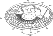
Fig. 8 is the perspective view of vital part, and this figure is used to illustrate the pond cover of pond assembly of the dish-washing machine of the present invention's second preferred implementation;
Fig. 9 shows the cross section that dissects along Fig. 8 center line I-I;
Figure 10 is the bottom perspective view of pond cover shown in Figure 8;
The bottom perspective view of Figure 11 is used to explain the state that is assemblied in the upper shell on the pond cover downside;
The schematic diagram of Figure 12 to 14 shows the cross section of vital part respectively, is used to illustrate the pond assembly middle filtrator support section of the dish-washing machine of the present invention's second preferred implementation;
The decomposition diagram of Figure 15 is used to explain the dish-washing machine pond assembly of the present invention's the 3rd preferred implementation;
The decomposition diagram of Figure 16 is used for illustrating the pond assembly filter screen mounting structure of the dish-washing machine of the present invention's the 3rd preferred implementation;
Figure 17 and each state diagram of 18 are used for illustrating the filter screen of pond assembly of dish-washing machine of the present invention's the 3rd preferred implementation and the relation between the disposer;
The decomposition diagram of Figure 19 is used for illustrating the drain chamber structure of pond assembly of the dish-washing machine of the present invention's the 4th preferred implementation;
The cross section that Figure 20 and 21 illustrates respectively is used for illustrating the inside structure of pond assembly drip chamber of the dish-washing machine of the present invention's the 4th preferred implementation;
The perspective view of Figure 22 is used to illustrate the situation of discharging washings and foreign matter between draining period from soil chamber.
The specific embodiment
Preferred implementations more of the present invention are described below with reference to the accompanying drawings.
The dish-washing machine of the present invention's first preferred implementation has proposed circulation and a series of flow passage structure of washings, to be used for removing foreign matter in cyclic process from washings.
That is to say that in the present invention's first preferred implementation, the washings that dish-washing machine is pumped a part are supplied with soil chamber by the drip chamber that is used for filtering from washings foreign matter, these contents will be for a more detailed description below.
Fig. 1 schematically shows the dish-washing machine of the present invention's one preferred implementation.
That is to say, the dish-washing machine of the present invention's one preferred implementation comprise main body 10, basin 20, upper/ lower spray arm 41 and 42, on/ lower carriage 31 and 32, and pond assembly 50.
Be provided with upper spray arm 41 and lower spray arm 42 with on being in/tableware on the lower carriage 31 and 32 sprays washings.Upper spray arm 41 is arranged on the upper space of basin, and lower spray arm 41 is arranged on the lower space of basin 20.
Tableware is placed on upper bracket 31 and the lower carriage 32.Upper bracket 31 is arranged on the upside of upper spray arm 41 of the upper space of basin 20, and lower carriage 32 is arranged on the upside of lower spray arm 42 of the lower space of basin 20.
Fig. 2 shows the detailed structure of pond assembly.
To carry out more detailed description with reference to figure 2 to pond assembly 50.
To the pond housing 100 of pond assembly be described below.
Then the washing water pump unit 200 to the pond assembly is described.
Washing water pump unit 200 comprises the washing motor 210 that is fixed to pond housing 100 downsides, and is coupled to the impeller 220 of washing motor 210 by axle 211.
With reference to figure 2, the axle 211 of washing motor 210 passes hole 112 in the bottom of sunk part 110.Be provided with the disposer 230 of axle on 211 that is installed in washing motor 210, the foreign matter of fragmentation sunk part 110 washed water when this disposer is used for when washing motor 210 runnings disposer being rotated.
With reference to figure 2, drip chamber 300 is formed on a side of pond housing 100 bottoms.Drip chamber 300 and sunk part 110 form in pond housing 100 side by side.
At a side place of pond housing 100 that is a side of drip chamber 300 emptying pump 600 is installed.Emptying pump 600 will be discharged into the outside of dish-washing machine from the washings of sunk part 110 and drip chamber 300.
Emptying pump 600 comprises impeller housing 610, drain motor 620, reaches impeller 630.Impeller housing can form as one with pond housing 100.Have in a side of impeller housing 610 and to take over 640 and be used at this place connection discharging hose 80.Drain motor 620 is coupled by axle and impeller 630, and drain motor 620 is installed to impeller housing 610.
Below, the soil chamber in the assembly of pond 421 is described.
Below, the directing assembly 400 of pond assembly is described.
Directing assembly 400 comprises upper shell 410 and lower house 420, is used for being provided in the soil chamber 421 by drip chamber 300 by the washings of washing water pump unit 200 with pumping.
With reference to figure 2, upper shell 410 is arranged in the upper space of pond housing 100, and lower house 420 is arranged on below the upper space 100.
In the upper surface of upper shell 410, have sampling runner 411 and sprue 412 and 413.
The washings that sprue 412 and 413 will not be sent to sampling runner 411 are directed to upper spray arm 41 or lower spray arm 42 or upper spray arm 41 and lower spray arm 42 among both.
On the bottom surface of upper shell 410, be provided with a part that is used to place impeller 220 upper ends upper end receiving unit 414, be used to guide by the upper wash water flow passage 415 of the washings of impeller 220 pumpings and be used for the washings of pumping are guided to from upper wash water flow passage 415 outlet 416 of the upper outside of upper shell 100.Outlet 416 is communicated with sampling runner 411 and sprue 412 and 413.
Upper wash water flow passage 415 is around upper end receiving unit 414, and outlet 416 is formed on the place, end of upper wash water flow passage 415.
Therewith together, in the upper surface of upper shell 410, have in addition and the outlet 416 valve receiving units 417 that are communicated with.
With reference to figure 2, flow divider 430 has the bottom that is positioned on the pond housing 100, flow divider 430 is positioned on the valve receiving unit 417 when being installed in directing assembly 400 on the pond housing 100.For this reason, lower house 420 has installing hole 422 so that valve receiving unit and flow divider 430 pass through this place adaptably.Below pond housing 100, be provided with the operating mechanism 432 that under pond housing 100, is used to operate flow divider 430.As shown in Figure 2, operating mechanism 432 comprises the stepping motor of at least one rotational angle that is used for accurately controlling flow divider 430.
Upper surface in impeller bearing part 440 is provided with and is used for introducing the inlet 441 of water, the lower end receiving unit 442 and being used to that is used to receive the part of impeller 220 lower ends from sunk part 110 and guides the lower wash water flow passage 443 corresponding with upper wash water flow passage 415 by the washings of impeller 220 pumpings.
Lower end receiving unit 442 is around inlet 441,441 224 is communicated with and leads to the impeller 220 that is arranged on the lower end receiving unit 442 with entering the mouth and enter the mouth.Lower wash water flow passage 443 is around lower end receiving unit 442.
Simultaneously the syndeton between the syndeton between drip chamber 300 and the soil chamber 421 and sampling runner 411 and the drip chamber 300 is carried out more detailed description.
With reference to figure 2, lower house has the tube connector 451 that is positioned at the part place relative with drip chamber 300, is used for connecting between soil chamber 421 and drip chamber 300, and the lower end of tube connector 451 is connected to drip chamber 300.Fig. 3 shows the upper shell 410 that is installed on the pond housing 100 and the state of lower house 420, and Fig. 4 shows the details of the syndeton between tube connector 451 and the drip chamber 300.
With reference to figure 2, the outlet side at the sampling runner 411 of upper shell 410 has first discharge unit 452 that stretches out downwards.Lower house 420 has second discharge unit 453, and it stretches out towards tube connector 451 corresponding to first discharge unit 452.
Be communicated with the part of tube connector 451 upper ends referring to Fig. 3 and 4, the second discharge units 453, and the remainder of the upper end of tube connector 451 is communicated with soil chamber 421.
So, by the washings sequential flow that provides of sampling runner 411 cross first discharge unit 452, second discharge unit 453, and tube connector 451 be sent to drip chamber 300, and flow through tube connector 451 therefrom once more to soil chamber 421.
Below, the pond cover 500 of pond assembly is described.
With reference to figure 2, pond cover 500 covers the upper surface of pond housing 100, and forms the bottom of the basin 200 of dish-washing machine.
Through hole 510 is communicated with soil chamber 421, and recovery holes 520 is communicated with the inboard of pond housing 100.As described, the inboard of the inboard of pond housing 100 and soil chamber 421 separates.
In addition, unaccounted Reference numeral 113 expression heaters are used for selectively washings being heated.
Below, will the operation of the dish-washing machine of first preferred implementation of the present invention be described.
When the washing of tableware or flushing were controlled, washings were supplied to sunk part 110 by the water hole 111 of giving in the pond housing 100 that is connected to feed pipe 70.In this case, heater 113 heated scrub water according to demand.
Finish when feedwater soon, washing motor 210 runnings are with wheel rotor 220, from sunk part 110 pumping washings to outlet 416 at upper shell 410.That is to say, send washings along the axial pump of impeller 220, and along the radially discharge washings of impeller 220, so that flow to outlet 416 along the lower wash water flow passage.In this case, during washings were pumped, washings were fixed on disposer 230 bumps of axle on 211 of washing motor 210.
Then, washings are introduced to and export the 416 valve receiving units 417 that are communicated with, and wherein a part of washings are sent to sampling runner 411, and remainder is sent to sprue 412 and 413.
In this case, the flow divider 430 in the operated valve receiving unit 417, with washings guide to sprue 412 and 413 one of at least in.
For example, if only washings are fed to lower spray arm 42, the fin 431 of operation flow divider 430 is to close second sprue 413; If only washings are fed to upper spray arm 41, the fin 431 of operation flow divider 430 is to close first sprue 412; As shown in Figure 7, if washings are fed to upper spray arm 41 and lower spray arm 42, the fin 431 of then operating flow divider 430 with open primary flow passage 412 and 413 both.
In view of the above, the washings that are supplied to upper spray arm 41 and/or lower spray arm 42 can be sprayed onto on the upper bracket 31 and/or lower carriage 32 in the basin 20, be placed on tableware on upper bracket 31 and/or the lower carriage 32 with washing.
Simultaneously, a part of sequential flow of the washings that are pumped is crossed first discharge unit 452, second discharge unit 453 and tube connector 451 and is supplied to sampling runner 411, and be supplied to drip chamber 300, then, washings are provided to soil chamber 421 once more by drip chamber 300 and by tube connector 451.
In this case, density is retained in the drip chamber 300 than big or the heavier particle of weight in the foreign matter of washings, and the particle that density is less or weight is lighter is sent in the soil chamber 421 together with washings.
The washings that are sent to soil chamber 421 are by the through hole 510 on the pond cover 500, and washings spill into the inboard of basin 20 when the water surface rises gradually in the soil chamber 421.
In this case, flow through in the process of through hole 510 at washings, the foreign matter in the washings is filtered by the filter member on the through hole 510 530, and foreign matter is remained in the soil chamber 421.
In view of the above, have only the washings of no foreign matter to overflow to the inside of basin 20 and be introduced to the inboard of pond housing 100 by the recovery holes 520 that form at pond cover 500 peripheries, and with washing tableware and entering sunk part 110 therefrom once more from the washings that tableware is removed foreign matter.
Thereafter, repeat aforesaid series of steps, the foreign matter in the washings is constantly accumulated in the soil chamber 421.
As described, after washings are by sampling runner 411, the determining section of the washings that are pumped drip chamber 300, soil chamber 421, and filter member 530 in progressively be cleaned, and turn back to pond housing 100 once more.
In this case, though seem to have only a small amount of washings drip chamber 300, soil chamber 421, and filter member 530 in be filtered, but, therefore can have good washings strainability because washings are constantly filtered in whole washing or flushing process.
Simultaneously, under washing or flushing end or the dirty serious situation of washings, make emptying pump 600 runnings.
In this case, by emptying pump 600 by discharging hose 80 with washings and dirt from soil chamber 421, drip chamber 300, and pond housing 100 sunk part 110 be discharged to the outside of dish-washing machine.
Simultaneously, Fig. 8 to 11 shows the pond assembly of the dish-washing machine of the present invention's second preferred implementation respectively.
Referring to Fig. 8 and 9, the pond assembly in the dish-washing machine of the present invention's second preferred implementation is provided with a kind of modified structure of pond cover 500.
With reference to figure 9, the pond cover 500 of the dish-washing machine of the present invention's second preferred implementation is downward-sloping, and it more and more tilts towards circumference from basic part for central authorities.
That is to say that pond cover 500 is downward-sloping, it more and more tilts to the part that forms recovery holes 520 from the part that forms through hole 510.
A series of structures like this are used for reclaiming more swimmingly the washings that overflow to pond housing 100 by soil chamber 421.
And, preferably, also be provided with leakage preventive portion 540, the part that is used for separately being formed with the part of recovery holes 520 and is formed with through hole at the downside of pond cover 500.
The structure of leakage preventive portion 540 will be described with reference to figure 5.
Leakage preventive portion 540 is included as first leakage preventive rib 541 at upper shell 410 edges and as second leakage preventive rib 542 at lower house 420 edges.
First leakage preventive rib 541 closely contacts with the sidewall of upper shell 410, be used to prevent along sprue 412 and 413 and sampling runner 411 washing water flowing leak.
Second leakage preventive rib 542 prevents along upper wash water flow passage 415, lower wash water flow passage 443, reaches the leakage of soil chamber 421 washing water flowing.
For this reason, leakage preventive rib 541 and 542 is stretched out predetermined altitude from the downside of pond cover 500 respectively.As shown in figure 11, if upper shell 410 combines with pond cover 500, first leakage preventive rib 541 is around the sidewall of upper shell 410, to separate the inside of upper shell 410.Though not shown, second leakage preventive rib 542 also centers on the sidewall of lower house 420, to separate the soil chamber 421 in the lower house 420.
The embodiment of the filter member 530 in the structure of the pond cover 500 of the present invention's second preferred implementation will be described with reference to figure 8 to 11 below.
If first only that the filter screen mesh is the less filter 531 is installed on the pond cover 500, cause the hydraulic pressure that puts on first filter 531 higher easily, cause filter member 530 distortion; If second only that the filter screen mesh is the bigger filter 532 is installed on the pond cover 500, cause to filter out the fine particle of foreign matter easily.
Therefore, preferably the first little filter 531 of filter screen mesh is installed, and the second big filter 532 of filter screen mesh is installed at remaining through hole 510 place at some through hole 510 place.
In addition, support section 550 is set, is used for supporting filter member 530 in the part of the formation through hole 510 of pond cover.
By means of the hydraulic pressure that puts on this place from the circulation of washings, filter support section 550 can prevent that filter 531 and 532 from sinking or distortion.
For this reason, preferably make at least one side in the upside of filter support section 550 supporting filter members 530 and the downside.
With reference to Figure 12, an embodiment of the support component 550 of filter comprises at least one upper support fin 551 of the upper surface that is used for supporting filter member 530.
It is desirable to, suitably determine the quantity of upper support fin 551 according to the area of filter member 530.
Below, with reference to Figure 13, another embodiment of filter support component 550 comprises the lower support fin 552 of the lower surface that at least one is used for supporting filter member 530.
It is desirable to, suitably determine the quantity of lower support fin 552 according to the area of filter member 530.
Yet if the upper surface of supporting filter member 530 only, filter member 530 subsides downwards easily or is sprayed from upper spray arm 41 and lower spray arm 42 and the washings that fall to hitting filter member 530 damage.
In addition, if the lower surface of supporting filter member 530 only, filter member 530 is easily by from the hydraulic pressure of the washings of soil chamber 421 dischargings and upwards distortion.
So as shown in figure 14, preferably, the filter support section 550 of another preferred implementation comprises at least one lower support fin 552 and at least one upper support fin 551 according to the present invention.The downside of lower support fin 552 supporting filter members 530, and the upper surface of upper support fin 551 supporting filter members 530.
In this embodiment, if filter support section 550 comprises a plurality of support fins 551 and 552, preferably a plurality of support fins 551 and 552 are provided with at regular intervals.
During can preventing to wash, the structure of the filter support section 550 of the present invention's second preferred implementation sink or distortion owing to hydraulic pressure causes the filter member 530 on place, the end through hole 510.
In addition, the pond cover 500 of the inclination of the present invention's second preferred implementation can will be recovered to sunk part 110 in the pond housing 100 from the washings that soil chamber 421 is overflowed swimmingly by recovery holes 520.
Simultaneously, Figure 15 to 17 shows the pond assembly in the present invention the 3rd dish-washing machine preferred embodiment by way of parenthesis respectively.
With reference to Figure 15, the dish-washing machine of the present invention's the 3rd preferred implementation is provided with a series of structures that can tentatively filter foreign matter before washings longshore current road flows into the pond assembly, below with reference to these accompanying drawings they is carried out more detailed description.
Moreover the dish-washing machine pond assembly of the present invention's the 3rd preferred implementation comprises filter screen 700.
Subsidiary with reference to the accompanying drawings 16, filter screen 700 can be introduced into from the sunk parts 110 in the pond housing 100 washings of lower house 420 and tentatively filter out foreign matter.
Preferably filter screen 700 is fixed on the bottom of the sunk part 110 in the pond housing 100, is used for fixing filter screen 700, so that filter screen 700 can filter foreign matter swimmingly and can not produce vibrations owing to the circulation of washings from washings with colluding 114.
At least form one and collude 114.Preferably be provided with symmetrically and collude 114.
Accompanying drawing 17 is the figure that are used to explain relation between filter screen 700 and the disposer 230.
That is to say that filter screen 700 is installed on the axle 211 of washing motor 210.The preferred axle that is located under the filter screen 700 that utilizes is coupled to disposer 230 on the washing motor 210.Certainly, disposer 230 also can be disposed in filter screen 700 tops.
Preferably, disposer 230 has the width L2 greater than the diameter L1 of through hole 710 in filter screen 700, directly passes through hole 710 to prevent foreign matter not to be subjected to the filtration of filter screen 700 and arrives lower house 420.
Certainly, also can be as shown in figure 18, the width L3 of disposer 230 can form the diameter L1 less than through hole 710.
Generally speaking, during the pumping washings, a series of structures of the present invention's the 3rd preferred implementation can make foreign matter 230 be smashed to pieces by disposer 230 and tentatively filter by filter screen 700.
Therefore, can make by sprue 412 and 413 foreign matter minimum in the washings that spray arm 41 and 42 provides.
In addition, even by drip chamber 300 washings are offered soil chamber 421 along sampling runner 411, and overflow by the through hole 510 in the pond cover 500, because therefore the obstruction minimum that the filter member 530 in each through hole 510 is subjected to reduces the pressure on the filter member 530.
Simultaneously, Figure 19 to 21 shows the internal structure of drip chamber 300 in the dish-washing machine pond assembly of the present invention's the 4th preferred implementation respectively.
Referring to Figure 19 to 21, the dish-washing machine pond assembly of the present invention's the 4th preferred implementation is provided with the drip chamber 300 that has through the internal structure of remodeling.
The internal structure of drip chamber 300 can tentatively keep foreign matter in drip chamber 300, this will carry out more detailed description below.
With reference to Figure 19, the drip chamber 300 of the present invention's the 4th preferred implementation comprises the housing 310 that is formed with predetermined inner space.
In more detail, referring to Figure 20 and 21, in order to be communicated with directing assembly 400 and drip chamber 300, can with first discharge unit 452, second discharge unit 453, and tube connector 451 be connected to the top part of housing 310, this describes in the present invention's first preferred implementation.In drip chamber 300, have fin 330 and be used for securely first discharge unit 452 and second discharge unit 453 being combined with tube connector 451.
Simultaneously, drip chamber 300 comprises valve part 320, is used for making selectively the drip chamber 300 that is communicated with directing assembly 400 to be communicated with sunk part 110 in the pond housing 100.
Being communicated with of first osculum 311 and sunk part 110 opened or closed to valve part 320 selectively.In this case, operated valve part 320 because the pressure of circulated washing water makes drip chamber 300 be communicated with sunk part 110 in the pond housing 100 in drip chamber 300, is perhaps separated drip chamber 300 and sunk part 110.
For this reason, valve part 320 is preferably check-valves.It only allows water to flow along a direction.That is to say that only begin when sunk part 110 flows to drip chamber 300 at washings, by means of the pressure of washings, valve part 320 is opened first osculum 311.
In this embodiment of the present invention, valve part 320 comprises the valve body 321 that is used for On/Off first osculum 311 and is used for valve body 321 is fixed to standing part 322 on the drip chamber 300.As shown in figure 19, standing part 322 is inserted in the sunk part 331 in the fin 330, so that be maintained fixed part 322 securely.
In addition, in this case, preferred valve body 321 has and is used to the projection 323 inserting and cooperate with first osculum 311.
Specifically, valve part 320 can be made by elastomeric material, when the pressure by washings makes valve part strain, opens first osculum 311.
In addition, standing part 322 can have hinge, when valve part 320 is opened first osculum 311 when standing part 322 is swung.
The operation of the valve part 320 of the present invention's the 4th preferred implementation will be described with reference to Figure 20 and 21.
As shown in figure 21, when discharging washings, emptying pump 600 runnings make washings flow along the direction that emptying pump 600 is installed from drip chamber 300.
Meanwhile, because the suction that emptying pump 600 produces and begin to flow to the pressure of the washings of drip chamber 300 from sunk part 110, valve part 320 actions in the drip chamber 300 and open first osculum 311.
Therefore, between the washings draining period, drip chamber 300 not only is communicated with directing assembly 400 but also with sunk part 110.
In the end, emptying pump 600 can be discharged into washings the outside of dish-washing machine by drip chamber 300 from directing assembly 400 and sunk part 110.The schematic diagram of Figure 22 is used for understanding better the process of discharging foreign matters from the soil chamber 421 in the directing assembly 400 by drip chamber 300.
In this case, by the adapter 640 of emptying pump 600, be discharged in the discharging hose 80 by the washings of emptying pump 600 pumpings.
Simultaneously, with reference to Figure 20, when tableware is washed, washings from directing assembly 400 sequentially by first discharge unit 452, second discharge unit 453, and tube connector 451 flow to drip chamber 300 continuously.
In this case, the valve part 320 in the drip chamber 300 makes first osculum 311 keep closed condition owing to be introduced into the pressure of washings wherein, so that sunk part 110 separates with drip chamber 300.
Therefore, during wash dining set, drip chamber 300 forms the independent runner that only is communicated with directing assembly 400.Independent runner like this makes washings flow to the soil chamber 421 of directing assembly 400 by drip chamber 300.That is to say that washings neither are discharged into the outside of dish-washing machine by discharging hose 80, also do not flow in the sunk part 110.
In this case, drip chamber 300 is positioned in directing assembly 400 belows.Therefore, washings from directing assembly 400 by first discharge unit 452, second discharge unit 453, and tube connector 451 flow to drip chamber 300 downwards.Then, after the part 451a of washings by the tube connector 451 that is communicated with soil chamber 421 upwards flowed, washings flow in the soil chamber 421.
Washings flow to by drip chamber 300 soil chamber 421 during because gravity, the bottom of foreign matter from washing depositing in water collection to drip chamber 300.Particularly, the heavy collection of the particle of heavier in the foreign matter (density height) is in drip chamber 300, and light foreign particles flows in the soil chamber 421 simultaneously.
In this case, as described in first embodiment, the foreign matter that flows in the soil chamber 421 is retained in soil chamber 421.
In the end, because drip chamber 300 has tentatively been removed foreign matter, the foreign particles density that soil chamber 300 is admitted is lower, stops up the probability of pond cover through hole 510 middle filtrator members 530 and can reduce to minimum.
Simultaneously, similar with the embodiment of former description, dish-washing machine of the present invention can also have the embodiment of some remodeling.
That is to say that spy's card of all features of the series structure that proposes in all of the embodiments of the present invention or the series structure of advising all can be applicable to dish-washing machine of the present invention in arbitrary embodiment.Obviously, for a person skilled in the art, under the situation that does not exceed design of the present invention or scope, can make various remodeling and conversion.Therefore, the present invention tries hard to contain of the present invention various remodeling and conversion and their equivalents in the scope that falls into the claims statement.
Industrial applicibility
As described, the structure of improved dish-washing machine of the present invention can reclaim washings effectively, and therefore, the present invention has the favorable industrial applicability.
Claims (7)
1. dish-washing machine comprises:
Be used to preserve the pond housing of washings;
The washings water pump unit that is used for the pumping washings;
Be used to receive the drip chamber of the washings that are washed the unit pumping of water water pump;
Be in described drip chamber top, be used for after washings are by described drip chamber, receiving the soil chamber of washings;
Be used to guide the washings that are washed the unit pumping of water water pump to offer the directing assembly of described soil chamber through drip chamber; With
Be covered in the pond cover of the upper surface of described pond housing, this pond cover has a plurality of through holes that are used for washings are directed to directing assembly, and a plurality of washings that are used for being discharged by described through hole are recovered to the recovery holes of described pond housing.
2. dish-washing machine as claimed in claim 1, wherein, described through hole is formed at the inboard of described pond cover, and described recovery holes is formed at the exterior section of described through hole.
3. dish-washing machine as claimed in claim 2, wherein, described pond cover has from the part that is formed with described through hole to the more and more downward-sloping upper surface of the part that is formed with described recovery holes.
4. dish-washing machine as claimed in claim 2 also comprises the filter member that is arranged at each through hole.
5. dish-washing machine as claimed in claim 4, wherein, described filter member comprises:
First filter and second filter, each filter has a plurality of opening of sieves, and the opening of sieve of wherein said second filter is greater than the opening of sieve of described first filter.
6. dish-washing machine as claimed in claim 5, wherein, described first filter and second filter form as one.
7. dish-washing machine as claimed in claim 4, wherein, described pond cover also comprises the inboard that is arranged on through hole, be used for supporting the upside of described filter member and downside filter support section one of at least.
Applications Claiming Priority (8)
| Application Number | Priority Date | Filing Date | Title |
|---|---|---|---|
| KR10-2004-0074477 | 2004-09-17 | ||
| KR1020040074632A KR100686111B1 (en) | 2004-09-17 | 2004-09-17 | Driving apparatus of the dish washer |
| KR1020040074477A KR100617158B1 (en) | 2004-09-17 | 2004-09-17 | structure for driving apparatus of dishwasher |
| KR10-2004-0074632 | 2004-09-17 | ||
| KR1020040075850A KR100617161B1 (en) | 2004-09-22 | 2004-09-22 | driving apparatus of dishwasher |
| KR1020040075929A KR100617123B1 (en) | 2004-09-22 | 2004-09-22 | driving apparatus of the dish washer |
| KR10-2004-0075850 | 2004-09-22 | ||
| KR10-2004-0075929 | 2004-09-22 |
Related Parent Applications (1)
| Application Number | Title | Priority Date | Filing Date |
|---|---|---|---|
| CN200580013955XA Division CN1950015B (en) | 2004-09-17 | 2005-09-15 | Dishwasher |
Publications (2)
| Publication Number | Publication Date |
|---|---|
| CN101884520A CN101884520A (en) | 2010-11-17 |
| CN101884520B true CN101884520B (en) | 2011-12-07 |
Family
ID=36060270
Family Applications (2)
| Application Number | Title | Priority Date | Filing Date |
|---|---|---|---|
| CN2010102315737A Expired - Fee Related CN101884521B (en) | 2004-09-17 | 2005-09-15 | Dishwasher |
| CN2010102315686A Expired - Fee Related CN101884520B (en) | 2004-09-17 | 2005-09-15 | Dishwasher |
Family Applications Before (1)
| Application Number | Title | Priority Date | Filing Date |
|---|---|---|---|
| CN2010102315737A Expired - Fee Related CN101884521B (en) | 2004-09-17 | 2005-09-15 | Dishwasher |
Country Status (7)
| Country | Link |
|---|---|
| US (1) | US7726324B2 (en) |
| EP (2) | EP2399501B1 (en) |
| JP (1) | JP4740247B2 (en) |
| CN (2) | CN101884521B (en) |
| AU (1) | AU2005283213B2 (en) |
| RU (1) | RU2339292C2 (en) |
| WO (1) | WO2006031064A1 (en) |
Families Citing this family (10)
| Publication number | Priority date | Publication date | Assignee | Title |
|---|---|---|---|---|
| KR100772225B1 (en) * | 2004-12-07 | 2007-11-01 | 엘지전자 주식회사 | A sump of a dish washer |
| KR20080028521A (en) * | 2006-09-27 | 2008-04-01 | 엘지전자 주식회사 | Sump for dish washer |
| US8424546B2 (en) * | 2008-07-15 | 2013-04-23 | Electrolux Home Products, Inc. | Sump assembly for a dishwasher, and associated method |
| KR101507803B1 (en) * | 2008-08-21 | 2015-04-03 | 엘지전자 주식회사 | Dish washer |
| US9402525B2 (en) | 2013-03-15 | 2016-08-02 | Stephen R. Ellebracht | Dishwasher-dining table having rotatable tabletop |
| US9888827B2 (en) * | 2015-04-08 | 2018-02-13 | Haier Us Appliance Solutions, Inc. | Dishwasher appliance and a method for forming a unitary tub |
| CN106140761A (en) * | 2015-04-23 | 2016-11-23 | 北京信智天成科技有限公司 | basin assembly and cleaning machine |
| KR102541170B1 (en) * | 2016-06-10 | 2023-06-08 | 엘지전자 주식회사 | Method for controlling water-supply of a dishwasher |
| CN107970003A (en) * | 2017-12-12 | 2018-05-01 | 浙江帅丰电器股份有限公司 | A kind of dish-washing machine easy to clean |
| DE102019212952B4 (en) * | 2019-08-28 | 2023-05-11 | Blanco Gmbh + Co Kg | Cleaning device and method for operating a cleaning device |
Family Cites Families (26)
| Publication number | Priority date | Publication date | Assignee | Title |
|---|---|---|---|---|
| GB901476A (en) | 1957-07-31 | 1962-07-18 | Bulpitt And Sons Ltd | Improvements in dish-washing machines |
| US4150680A (en) | 1978-05-26 | 1979-04-24 | Whirlpool Corporation | Dishwasher soil separator |
| AU527001B2 (en) | 1978-12-29 | 1983-02-10 | Hobart International Inc. | Warewasher bypass soil collector |
| US4243431A (en) | 1979-06-14 | 1981-01-06 | Whirlpool Corporation | Dishwasher soil separator |
| US4392891A (en) * | 1980-07-02 | 1983-07-12 | Hobart Corporation | Dishwasher soil collecting circuit |
| US4448359A (en) | 1982-06-10 | 1984-05-15 | Hobart Corporation | Combination drain pump and grinding apparatus |
| IT211726Z2 (en) | 1987-04-08 | 1989-04-07 | Zanussi Elettrodomestici | DISHWASHER MACHINE WITH ATUPOULENT RECIRCULATION FILTER. |
| SU1738259A1 (en) | 1990-05-07 | 1992-06-07 | Производственное объединение "Волгоградский тракторный завод им.Ф.Э.Дзержинского" | Dish washing machine |
| US5377707A (en) | 1993-11-01 | 1995-01-03 | White Consolidated Industries, Inc. | Dishwasher pump and filtration system |
| DE4418523A1 (en) | 1994-05-27 | 1995-11-30 | Licentia Gmbh | Domestic dishwashing machine float-controlled filter combination |
| IN186362B (en) | 1995-07-01 | 2001-08-18 | Lg Electronics Inc | |
| US5779812A (en) * | 1995-08-25 | 1998-07-14 | Whirlpool Corporation | Multi-mesh mechanical filter screen system for dishwashers |
| US5803100A (en) | 1995-08-25 | 1998-09-08 | Whirlpool Corporation | Soil separation channel for dishwasher pump system |
| KR970010423B1 (en) * | 1995-09-19 | 1997-06-26 | 엘지전자 주식회사 | Method and processing for disposal garbage of a dishwasher |
| GB9525590D0 (en) | 1995-12-14 | 1996-02-14 | British Gas Plc | Pipe repair clamp |
| US5909743A (en) | 1997-09-10 | 1999-06-08 | Whirlpool Corporation | Automatic purge filtration system for a dishwasher |
| KR19980057987A (en) * | 1996-12-30 | 1998-09-25 | 배순훈 | Microwave temperature control method |
| KR19980057987U (en) | 1997-02-17 | 1998-10-26 | 김광호 | Dishwasher with check valve |
| KR200196942Y1 (en) | 1998-07-23 | 2000-12-01 | 윤종용 | Dish washer |
| US6418943B1 (en) | 1999-06-04 | 2002-07-16 | Whirlpool Corporation | Wash liquid circulation system for a dishwasher |
| KR100339370B1 (en) | 2000-01-31 | 2002-06-03 | 구자홍 | pump system of dish washer |
| US6641058B2 (en) * | 2000-12-28 | 2003-11-04 | General Electric Company | Dishwasher spray arm hub and conduit assembly |
| US7028697B2 (en) | 2002-05-03 | 2006-04-18 | Whirlpool Corporation | In-sink dishwasher |
| KR100457589B1 (en) * | 2002-11-28 | 2004-11-17 | 엘지전자 주식회사 | A dish washer |
| KR100606823B1 (en) | 2004-05-28 | 2006-08-01 | 엘지전자 주식회사 | apparatus of the dishwasher |
| US7409962B2 (en) * | 2004-08-31 | 2008-08-12 | Whirlpool Corporation | Dishwasher pump with integrated inlet/outlet portion |
-
2005
- 2005-09-15 RU RU2006140245/12A patent/RU2339292C2/en not_active IP Right Cessation
- 2005-09-15 WO PCT/KR2005/003051 patent/WO2006031064A1/en active Application Filing
- 2005-09-15 EP EP11180394.6A patent/EP2399501B1/en not_active Not-in-force
- 2005-09-15 CN CN2010102315737A patent/CN101884521B/en not_active Expired - Fee Related
- 2005-09-15 EP EP05808756A patent/EP1788922A1/en not_active Ceased
- 2005-09-15 US US10/554,864 patent/US7726324B2/en not_active Expired - Fee Related
- 2005-09-15 CN CN2010102315686A patent/CN101884520B/en not_active Expired - Fee Related
- 2005-09-15 AU AU2005283213A patent/AU2005283213B2/en not_active Ceased
- 2005-09-15 JP JP2007532239A patent/JP4740247B2/en not_active Expired - Fee Related
Also Published As
| Publication number | Publication date |
|---|---|
| RU2006140245A (en) | 2008-05-20 |
| EP1788922A1 (en) | 2007-05-30 |
| US20070261725A1 (en) | 2007-11-15 |
| EP2399501A1 (en) | 2011-12-28 |
| JP4740247B2 (en) | 2011-08-03 |
| WO2006031064A1 (en) | 2006-03-23 |
| CN101884521A (en) | 2010-11-17 |
| CN101884520A (en) | 2010-11-17 |
| EP2399501B1 (en) | 2015-09-02 |
| US7726324B2 (en) | 2010-06-01 |
| CN101884521B (en) | 2011-12-07 |
| JP2008513092A (en) | 2008-05-01 |
| AU2005283213A1 (en) | 2006-03-23 |
| AU2005283213B2 (en) | 2009-05-07 |
| RU2339292C2 (en) | 2008-11-27 |
Similar Documents
| Publication | Publication Date | Title |
|---|---|---|
| CN101884520B (en) | Dishwasher | |
| US5779812A (en) | Multi-mesh mechanical filter screen system for dishwashers | |
| US6782899B2 (en) | Dishwasher | |
| EP1386575A1 (en) | Dishwashing machine with macerator filter caused to rotate by the wash liquid flow | |
| KR100438270B1 (en) | Dishwasher | |
| CN1950015B (en) | Dishwasher | |
| CN108316453A (en) | Novel rainwater collection system | |
| CN217659734U (en) | A sediment basket structure and cleaning machine for cleaning machine | |
| CN109717804B (en) | Slag collecting structure for cleaning machine and cleaning machine applying same | |
| JP4094115B2 (en) | Tapping machine filtration device and grinding dust removal device | |
| CN212854910U (en) | Anti-overflow anti-washing device of aquaculture rotary drum | |
| CN212853387U (en) | Water circulation filtering and oil removing device of commercial dish washing machine | |
| JP3988558B2 (en) | Dishwasher leftover collection equipment | |
| CN214760961U (en) | Slag basket and water tank type cleaning machine with same | |
| KR100457596B1 (en) | Filter assembly of dish washer | |
| KR100511967B1 (en) | Filter assembly of dish washer | |
| CN217974615U (en) | Vegetable washer capable of removing floating objects | |
| CN214270301U (en) | Stainless steel oil-water separator | |
| CN214809141U (en) | Water circulation floor-cleaning vehicle | |
| CN103502153A (en) | Fluid pump volute diversion system, solids collections system and related methods for a washing machine | |
| CN107558365B (en) | A kind of novel bridge draining anti-block apparatus | |
| CN210080194U (en) | Glass apron high pressure cleaning flushing tank | |
| CN207169137U (en) | A kind of air scrubbing filter | |
| JP4006757B2 (en) | Sand removal system | |
| CN205432001U (en) | Vegetable washing machine |
Legal Events
| Date | Code | Title | Description |
|---|---|---|---|
| C06 | Publication | ||
| PB01 | Publication | ||
| C10 | Entry into substantive examination | ||
| SE01 | Entry into force of request for substantive examination | ||
| C14 | Grant of patent or utility model | ||
| GR01 | Patent grant | ||
| CF01 | Termination of patent right due to non-payment of annual fee | ||
| CF01 | Termination of patent right due to non-payment of annual fee |
Granted publication date: 20111207 Termination date: 20170915 |