CN101878553A - Light-emitting element, light-emitting device, and electronic device - Google Patents
Light-emitting element, light-emitting device, and electronic device Download PDFInfo
- Publication number
- CN101878553A CN101878553A CN2008801188580A CN200880118858A CN101878553A CN 101878553 A CN101878553 A CN 101878553A CN 2008801188580 A CN2008801188580 A CN 2008801188580A CN 200880118858 A CN200880118858 A CN 200880118858A CN 101878553 A CN101878553 A CN 101878553A
- Authority
- CN
- China
- Prior art keywords
- light
- emitting component
- metal
- organic compound
- organic
- Prior art date
- Legal status (The legal status is an assumption and is not a legal conclusion. Google has not performed a legal analysis and makes no representation as to the accuracy of the status listed.)
- Pending
Links
- 150000002894 organic compounds Chemical class 0.000 claims abstract description 128
- KBBSSGXNXGXONI-UHFFFAOYSA-N phenanthro[9,10-b]pyrazine Chemical group C1=CN=C2C3=CC=CC=C3C3=CC=CC=C3C2=N1 KBBSSGXNXGXONI-UHFFFAOYSA-N 0.000 claims abstract description 68
- 239000003446 ligand Substances 0.000 claims abstract description 19
- 125000004432 carbon atom Chemical group C* 0.000 claims description 105
- 229910052799 carbon Inorganic materials 0.000 claims description 79
- 229910052751 metal Inorganic materials 0.000 claims description 62
- 239000002184 metal Substances 0.000 claims description 62
- XSCHRSMBECNVNS-UHFFFAOYSA-N quinoxaline Chemical compound N1=CC=NC2=CC=CC=C21 XSCHRSMBECNVNS-UHFFFAOYSA-N 0.000 claims description 56
- 239000001257 hydrogen Substances 0.000 claims description 48
- 229910052739 hydrogen Inorganic materials 0.000 claims description 48
- 125000003545 alkoxy group Chemical group 0.000 claims description 45
- 125000000217 alkyl group Chemical group 0.000 claims description 45
- UFHFLCQGNIYNRP-UHFFFAOYSA-N Hydrogen Chemical compound [H][H] UFHFLCQGNIYNRP-UHFFFAOYSA-N 0.000 claims description 35
- 125000003118 aryl group Chemical group 0.000 claims description 33
- -1 aromatic amine compound Chemical class 0.000 claims description 32
- 241001597008 Nomeidae Species 0.000 claims description 29
- 230000005525 hole transport Effects 0.000 claims description 26
- 125000005843 halogen group Chemical group 0.000 claims description 25
- BASFCYQUMIYNBI-UHFFFAOYSA-N platinum Chemical compound [Pt] BASFCYQUMIYNBI-UHFFFAOYSA-N 0.000 claims description 24
- 150000001450 anions Chemical class 0.000 claims description 19
- 229910052741 iridium Inorganic materials 0.000 claims description 19
- UJOBWOGCFQCDNV-UHFFFAOYSA-N 9H-carbazole Chemical compound C1=CC=C2C3=CC=CC=C3NC2=C1 UJOBWOGCFQCDNV-UHFFFAOYSA-N 0.000 claims description 18
- GKOZUEZYRPOHIO-UHFFFAOYSA-N iridium atom Chemical compound [Ir] GKOZUEZYRPOHIO-UHFFFAOYSA-N 0.000 claims description 17
- 125000004423 acyloxy group Chemical group 0.000 claims description 16
- 150000002431 hydrogen Chemical class 0.000 claims description 13
- 229910052697 platinum Inorganic materials 0.000 claims description 12
- 150000004696 coordination complex Chemical class 0.000 claims description 8
- 150000002390 heteroarenes Chemical class 0.000 claims description 7
- 238000004519 manufacturing process Methods 0.000 abstract 1
- 125000002524 organometallic group Chemical group 0.000 abstract 1
- 239000010410 layer Substances 0.000 description 157
- 239000000463 material Substances 0.000 description 67
- 150000001875 compounds Chemical class 0.000 description 47
- CUJRVFIICFDLGR-UHFFFAOYSA-N acetylacetonate Chemical compound CC(=O)[CH-]C(C)=O CUJRVFIICFDLGR-UHFFFAOYSA-N 0.000 description 29
- 239000000758 substrate Substances 0.000 description 25
- YRKCREAYFQTBPV-UHFFFAOYSA-N acetylacetone Chemical compound CC(=O)CC(C)=O YRKCREAYFQTBPV-UHFFFAOYSA-N 0.000 description 22
- 230000027756 respiratory electron transport chain Effects 0.000 description 22
- 238000000034 method Methods 0.000 description 20
- 230000005540 biological transmission Effects 0.000 description 19
- 239000000126 substance Substances 0.000 description 19
- 239000010408 film Substances 0.000 description 18
- JUJWROOIHBZHMG-UHFFFAOYSA-N Pyridine Chemical compound C1=CC=NC=C1 JUJWROOIHBZHMG-UHFFFAOYSA-N 0.000 description 17
- UFVXQDWNSAGPHN-UHFFFAOYSA-K bis[(2-methylquinolin-8-yl)oxy]-(4-phenylphenoxy)alumane Chemical compound [Al+3].C1=CC=C([O-])C2=NC(C)=CC=C21.C1=CC=C([O-])C2=NC(C)=CC=C21.C1=CC([O-])=CC=C1C1=CC=CC=C1 UFVXQDWNSAGPHN-UHFFFAOYSA-K 0.000 description 16
- 238000009434 installation Methods 0.000 description 16
- 238000001704 evaporation Methods 0.000 description 15
- 230000008020 evaporation Effects 0.000 description 15
- LFQSCWFLJHTTHZ-UHFFFAOYSA-N Ethanol Chemical compound CCO LFQSCWFLJHTTHZ-UHFFFAOYSA-N 0.000 description 14
- 238000006243 chemical reaction Methods 0.000 description 14
- 230000000694 effects Effects 0.000 description 13
- 230000005284 excitation Effects 0.000 description 13
- 239000000203 mixture Substances 0.000 description 13
- UHOVQNZJYSORNB-UHFFFAOYSA-N Benzene Chemical compound C1=CC=CC=C1 UHOVQNZJYSORNB-UHFFFAOYSA-N 0.000 description 11
- 238000002347 injection Methods 0.000 description 11
- 239000007924 injection Substances 0.000 description 11
- XKRFYHLGVUSROY-UHFFFAOYSA-N Argon Chemical compound [Ar] XKRFYHLGVUSROY-UHFFFAOYSA-N 0.000 description 10
- 230000005264 electron capture Effects 0.000 description 10
- 238000004770 highest occupied molecular orbital Methods 0.000 description 10
- 239000000243 solution Substances 0.000 description 9
- IJGRMHOSHXDMSA-UHFFFAOYSA-N Atomic nitrogen Chemical compound N#N IJGRMHOSHXDMSA-UHFFFAOYSA-N 0.000 description 8
- 239000004973 liquid crystal related substance Substances 0.000 description 8
- 125000001997 phenyl group Chemical group [H]C1=C([H])C([H])=C(*)C([H])=C1[H] 0.000 description 8
- UMJSCPRVCHMLSP-UHFFFAOYSA-N pyridine Natural products COC1=CC=CN=C1 UMJSCPRVCHMLSP-UHFFFAOYSA-N 0.000 description 8
- 238000010189 synthetic method Methods 0.000 description 8
- 238000010586 diagram Methods 0.000 description 7
- KDLHZDBZIXYQEI-UHFFFAOYSA-N palladium Substances [Pd] KDLHZDBZIXYQEI-UHFFFAOYSA-N 0.000 description 7
- 238000006722 reduction reaction Methods 0.000 description 7
- 239000002904 solvent Substances 0.000 description 7
- OKKJLVBELUTLKV-UHFFFAOYSA-N Methanol Chemical compound OC OKKJLVBELUTLKV-UHFFFAOYSA-N 0.000 description 6
- VYPSYNLAJGMNEJ-UHFFFAOYSA-N Silicium dioxide Chemical compound O=[Si]=O VYPSYNLAJGMNEJ-UHFFFAOYSA-N 0.000 description 6
- 229910045601 alloy Inorganic materials 0.000 description 6
- 239000000956 alloy Substances 0.000 description 6
- 230000004888 barrier function Effects 0.000 description 6
- 239000002585 base Substances 0.000 description 6
- 230000015572 biosynthetic process Effects 0.000 description 6
- ZUOUZKKEUPVFJK-UHFFFAOYSA-N diphenyl Chemical compound C1=CC=CC=C1C1=CC=CC=C1 ZUOUZKKEUPVFJK-UHFFFAOYSA-N 0.000 description 6
- 238000000295 emission spectrum Methods 0.000 description 6
- PQQKPALAQIIWST-UHFFFAOYSA-N oxomolybdenum Chemical compound [Mo]=O PQQKPALAQIIWST-UHFFFAOYSA-N 0.000 description 6
- 238000005381 potential energy Methods 0.000 description 6
- 239000000843 powder Substances 0.000 description 6
- GGTXYOVKMNRYMW-UHFFFAOYSA-N 3-phenylphenanthro[9,10-b]pyrazine Chemical compound C1=CC=CC=C1C1=CN=C(C=2C(=CC=CC=2)C=2C3=CC=CC=2)C3=N1 GGTXYOVKMNRYMW-UHFFFAOYSA-N 0.000 description 5
- ZMXDDKWLCZADIW-UHFFFAOYSA-N N,N-Dimethylformamide Chemical compound CN(C)C=O ZMXDDKWLCZADIW-UHFFFAOYSA-N 0.000 description 5
- REDXJYDRNCIFBQ-UHFFFAOYSA-N aluminium(3+) Chemical compound [Al+3] REDXJYDRNCIFBQ-UHFFFAOYSA-N 0.000 description 5
- 229910052786 argon Inorganic materials 0.000 description 5
- 239000011575 calcium Substances 0.000 description 5
- 238000000576 coating method Methods 0.000 description 5
- 239000008393 encapsulating agent Substances 0.000 description 5
- 235000019441 ethanol Nutrition 0.000 description 5
- 229910052736 halogen Inorganic materials 0.000 description 5
- 150000002367 halogens Chemical class 0.000 description 5
- MILUBEOXRNEUHS-UHFFFAOYSA-N iridium(3+) Chemical compound [Ir+3] MILUBEOXRNEUHS-UHFFFAOYSA-N 0.000 description 5
- 239000011777 magnesium Substances 0.000 description 5
- PXHVJJICTQNCMI-UHFFFAOYSA-N nickel Substances [Ni] PXHVJJICTQNCMI-UHFFFAOYSA-N 0.000 description 5
- 238000002360 preparation method Methods 0.000 description 5
- 125000000999 tert-butyl group Chemical group [H]C([H])([H])C(*)(C([H])([H])[H])C([H])([H])[H] 0.000 description 5
- 230000007704 transition Effects 0.000 description 5
- XLYOFNOQVPJJNP-UHFFFAOYSA-N water Substances O XLYOFNOQVPJJNP-UHFFFAOYSA-N 0.000 description 5
- 239000011701 zinc Substances 0.000 description 5
- VQGHOUODWALEFC-UHFFFAOYSA-N 2-phenylpyridine Chemical compound C1=CC=CC=C1C1=CC=CC=N1 VQGHOUODWALEFC-UHFFFAOYSA-N 0.000 description 4
- XTVSSVCFYQQNSA-UHFFFAOYSA-N 3-(3-fluorophenyl)phenanthro[9,10-b]pyrazine Chemical compound FC1=CC=CC(C=2N=C3C4=CC=CC=C4C4=CC=CC=C4C3=NC=2)=C1 XTVSSVCFYQQNSA-UHFFFAOYSA-N 0.000 description 4
- PEDCQBHIVMGVHV-UHFFFAOYSA-N Glycerine Chemical compound OCC(O)CO PEDCQBHIVMGVHV-UHFFFAOYSA-N 0.000 description 4
- NRTOMJZYCJJWKI-UHFFFAOYSA-N Titanium nitride Chemical compound [Ti]#N NRTOMJZYCJJWKI-UHFFFAOYSA-N 0.000 description 4
- XLOMVQKBTHCTTD-UHFFFAOYSA-N Zinc monoxide Chemical compound [Zn]=O XLOMVQKBTHCTTD-UHFFFAOYSA-N 0.000 description 4
- 239000012298 atmosphere Substances 0.000 description 4
- 239000002800 charge carrier Substances 0.000 description 4
- 238000006073 displacement reaction Methods 0.000 description 4
- 125000001495 ethyl group Chemical group [H]C([H])([H])C([H])([H])* 0.000 description 4
- 238000001914 filtration Methods 0.000 description 4
- 239000011521 glass Substances 0.000 description 4
- 239000012212 insulator Substances 0.000 description 4
- 125000003253 isopropoxy group Chemical group [H]C([H])([H])C([H])(O*)C([H])([H])[H] 0.000 description 4
- 125000001449 isopropyl group Chemical group [H]C([H])([H])C([H])(*)C([H])([H])[H] 0.000 description 4
- 229910052744 lithium Inorganic materials 0.000 description 4
- PQXKHYXIUOZZFA-UHFFFAOYSA-M lithium fluoride Chemical compound [Li+].[F-] PQXKHYXIUOZZFA-UHFFFAOYSA-M 0.000 description 4
- 125000002496 methyl group Chemical group [H]C([H])([H])* 0.000 description 4
- 229910000476 molybdenum oxide Inorganic materials 0.000 description 4
- 229910052757 nitrogen Inorganic materials 0.000 description 4
- 229910052763 palladium Inorganic materials 0.000 description 4
- 238000011084 recovery Methods 0.000 description 4
- 230000009467 reduction Effects 0.000 description 4
- 125000001424 substituent group Chemical group 0.000 description 4
- 125000004213 tert-butoxy group Chemical group [H]C([H])([H])C(O*)(C([H])([H])[H])C([H])([H])[H] 0.000 description 4
- DHDHJYNTEFLIHY-UHFFFAOYSA-N 4,7-diphenyl-1,10-phenanthroline Chemical compound C1=CC=CC=C1C1=CC=NC2=C1C=CC1=C(C=3C=CC=CC=3)C=CN=C21 DHDHJYNTEFLIHY-UHFFFAOYSA-N 0.000 description 3
- 229920000178 Acrylic resin Polymers 0.000 description 3
- 239000004925 Acrylic resin Substances 0.000 description 3
- PNEYBMLMFCGWSK-UHFFFAOYSA-N Alumina Chemical compound [O-2].[O-2].[O-2].[Al+3].[Al+3] PNEYBMLMFCGWSK-UHFFFAOYSA-N 0.000 description 3
- OYPRJOBELJOOCE-UHFFFAOYSA-N Calcium Chemical compound [Ca] OYPRJOBELJOOCE-UHFFFAOYSA-N 0.000 description 3
- 229910052691 Erbium Inorganic materials 0.000 description 3
- YCKRFDGAMUMZLT-UHFFFAOYSA-N Fluorine atom Chemical compound [F] YCKRFDGAMUMZLT-UHFFFAOYSA-N 0.000 description 3
- WHXSMMKQMYFTQS-UHFFFAOYSA-N Lithium Chemical compound [Li] WHXSMMKQMYFTQS-UHFFFAOYSA-N 0.000 description 3
- FYYHWMGAXLPEAU-UHFFFAOYSA-N Magnesium Chemical compound [Mg] FYYHWMGAXLPEAU-UHFFFAOYSA-N 0.000 description 3
- AZWHFTKIBIQKCA-UHFFFAOYSA-N [Sn+2]=O.[O-2].[In+3] Chemical compound [Sn+2]=O.[O-2].[In+3] AZWHFTKIBIQKCA-UHFFFAOYSA-N 0.000 description 3
- 229910052783 alkali metal Inorganic materials 0.000 description 3
- 150000001340 alkali metals Chemical class 0.000 description 3
- 229910052784 alkaline earth metal Inorganic materials 0.000 description 3
- 150000001342 alkaline earth metals Chemical class 0.000 description 3
- 239000004411 aluminium Substances 0.000 description 3
- 229910052782 aluminium Inorganic materials 0.000 description 3
- XAGFODPZIPBFFR-UHFFFAOYSA-N aluminium Chemical compound [Al] XAGFODPZIPBFFR-UHFFFAOYSA-N 0.000 description 3
- ATBAMAFKBVZNFJ-UHFFFAOYSA-N beryllium atom Chemical compound [Be] ATBAMAFKBVZNFJ-UHFFFAOYSA-N 0.000 description 3
- 235000010290 biphenyl Nutrition 0.000 description 3
- 239000004305 biphenyl Substances 0.000 description 3
- 229910052792 caesium Inorganic materials 0.000 description 3
- TVFDJXOCXUVLDH-UHFFFAOYSA-N caesium atom Chemical compound [Cs] TVFDJXOCXUVLDH-UHFFFAOYSA-N 0.000 description 3
- 229910052791 calcium Inorganic materials 0.000 description 3
- 239000011651 chromium Substances 0.000 description 3
- 238000009826 distribution Methods 0.000 description 3
- UYAHIZSMUZPPFV-UHFFFAOYSA-N erbium Chemical compound [Er] UYAHIZSMUZPPFV-UHFFFAOYSA-N 0.000 description 3
- 239000011737 fluorine Substances 0.000 description 3
- 229910052731 fluorine Inorganic materials 0.000 description 3
- 238000010438 heat treatment Methods 0.000 description 3
- 150000002484 inorganic compounds Chemical class 0.000 description 3
- 229910010272 inorganic material Inorganic materials 0.000 description 3
- 229920002521 macromolecule Polymers 0.000 description 3
- 229910052749 magnesium Inorganic materials 0.000 description 3
- 229910021645 metal ion Inorganic materials 0.000 description 3
- VLKZOEOYAKHREP-UHFFFAOYSA-N n-Hexane Chemical compound CCCCCC VLKZOEOYAKHREP-UHFFFAOYSA-N 0.000 description 3
- 229910052759 nickel Inorganic materials 0.000 description 3
- 229920003227 poly(N-vinyl carbazole) Polymers 0.000 description 3
- 229910052761 rare earth metal Inorganic materials 0.000 description 3
- 238000001953 recrystallisation Methods 0.000 description 3
- 238000004544 sputter deposition Methods 0.000 description 3
- 238000003786 synthesis reaction Methods 0.000 description 3
- 238000002834 transmittance Methods 0.000 description 3
- ODHXBMXNKOYIBV-UHFFFAOYSA-N triphenylamine Chemical compound C1=CC=CC=C1N(C=1C=CC=CC=1)C1=CC=CC=C1 ODHXBMXNKOYIBV-UHFFFAOYSA-N 0.000 description 3
- 238000001771 vacuum deposition Methods 0.000 description 3
- IYZMXHQDXZKNCY-UHFFFAOYSA-N 1-n,1-n-diphenyl-4-n,4-n-bis[4-(n-phenylanilino)phenyl]benzene-1,4-diamine Chemical compound C1=CC=CC=C1N(C=1C=CC(=CC=1)N(C=1C=CC(=CC=1)N(C=1C=CC=CC=1)C=1C=CC=CC=1)C=1C=CC(=CC=1)N(C=1C=CC=CC=1)C=1C=CC=CC=1)C1=CC=CC=C1 IYZMXHQDXZKNCY-UHFFFAOYSA-N 0.000 description 2
- SNTWKPAKVQFCCF-UHFFFAOYSA-N 2,3-dihydro-1h-triazole Chemical compound N1NC=CN1 SNTWKPAKVQFCCF-UHFFFAOYSA-N 0.000 description 2
- FQJQNLKWTRGIEB-UHFFFAOYSA-N 2-(4-tert-butylphenyl)-5-[3-[5-(4-tert-butylphenyl)-1,3,4-oxadiazol-2-yl]phenyl]-1,3,4-oxadiazole Chemical compound C1=CC(C(C)(C)C)=CC=C1C1=NN=C(C=2C=C(C=CC=2)C=2OC(=NN=2)C=2C=CC(=CC=2)C(C)(C)C)O1 FQJQNLKWTRGIEB-UHFFFAOYSA-N 0.000 description 2
- GEQBRULPNIVQPP-UHFFFAOYSA-N 2-[3,5-bis(1-phenylbenzimidazol-2-yl)phenyl]-1-phenylbenzimidazole Chemical compound C1=CC=CC=C1N1C2=CC=CC=C2N=C1C1=CC(C=2N(C3=CC=CC=C3N=2)C=2C=CC=CC=2)=CC(C=2N(C3=CC=CC=C3N=2)C=2C=CC=CC=2)=C1 GEQBRULPNIVQPP-UHFFFAOYSA-N 0.000 description 2
- AWXGSYPUMWKTBR-UHFFFAOYSA-N 4-carbazol-9-yl-n,n-bis(4-carbazol-9-ylphenyl)aniline Chemical compound C12=CC=CC=C2C2=CC=CC=C2N1C1=CC=C(N(C=2C=CC(=CC=2)N2C3=CC=CC=C3C3=CC=CC=C32)C=2C=CC(=CC=2)N2C3=CC=CC=C3C3=CC=CC=C32)C=C1 AWXGSYPUMWKTBR-UHFFFAOYSA-N 0.000 description 2
- DIVZFUBWFAOMCW-UHFFFAOYSA-N 4-n-(3-methylphenyl)-1-n,1-n-bis[4-(n-(3-methylphenyl)anilino)phenyl]-4-n-phenylbenzene-1,4-diamine Chemical compound CC1=CC=CC(N(C=2C=CC=CC=2)C=2C=CC(=CC=2)N(C=2C=CC(=CC=2)N(C=2C=CC=CC=2)C=2C=C(C)C=CC=2)C=2C=CC(=CC=2)N(C=2C=CC=CC=2)C=2C=C(C)C=CC=2)=C1 DIVZFUBWFAOMCW-UHFFFAOYSA-N 0.000 description 2
- VYZAMTAEIAYCRO-UHFFFAOYSA-N Chromium Chemical compound [Cr] VYZAMTAEIAYCRO-UHFFFAOYSA-N 0.000 description 2
- RTZKZFJDLAIYFH-UHFFFAOYSA-N Diethyl ether Chemical compound CCOCC RTZKZFJDLAIYFH-UHFFFAOYSA-N 0.000 description 2
- 101000837344 Homo sapiens T-cell leukemia translocation-altered gene protein Proteins 0.000 description 2
- 229910052774 Proactinium Inorganic materials 0.000 description 2
- CDBYLPFSWZWCQE-UHFFFAOYSA-L Sodium Carbonate Chemical compound [Na+].[Na+].[O-]C([O-])=O CDBYLPFSWZWCQE-UHFFFAOYSA-L 0.000 description 2
- HEMHJVSKTPXQMS-UHFFFAOYSA-M Sodium hydroxide Chemical compound [OH-].[Na+] HEMHJVSKTPXQMS-UHFFFAOYSA-M 0.000 description 2
- 102100028692 T-cell leukemia translocation-altered gene protein Human genes 0.000 description 2
- 229910052769 Ytterbium Inorganic materials 0.000 description 2
- PTFCDOFLOPIGGS-UHFFFAOYSA-N Zinc dication Chemical compound [Zn+2] PTFCDOFLOPIGGS-UHFFFAOYSA-N 0.000 description 2
- MWPLVEDNUUSJAV-UHFFFAOYSA-N anthracene Chemical compound C1=CC=CC2=CC3=CC=CC=C3C=C21 MWPLVEDNUUSJAV-UHFFFAOYSA-N 0.000 description 2
- 125000004429 atom Chemical group 0.000 description 2
- 230000008901 benefit Effects 0.000 description 2
- YXVFYQXJAXKLAK-UHFFFAOYSA-N biphenyl-4-ol Chemical compound C1=CC(O)=CC=C1C1=CC=CC=C1 YXVFYQXJAXKLAK-UHFFFAOYSA-N 0.000 description 2
- 238000009835 boiling Methods 0.000 description 2
- 229910052804 chromium Inorganic materials 0.000 description 2
- 239000011248 coating agent Substances 0.000 description 2
- 239000012141 concentrate Substances 0.000 description 2
- 238000010276 construction Methods 0.000 description 2
- 239000010949 copper Substances 0.000 description 2
- 238000000151 deposition Methods 0.000 description 2
- 238000013461 design Methods 0.000 description 2
- 238000001035 drying Methods 0.000 description 2
- 238000005516 engineering process Methods 0.000 description 2
- KTWOOEGAPBSYNW-UHFFFAOYSA-N ferrocene Chemical compound [Fe+2].C=1C=C[CH-]C=1.C=1C=C[CH-]C=1 KTWOOEGAPBSYNW-UHFFFAOYSA-N 0.000 description 2
- 239000011152 fibreglass Substances 0.000 description 2
- 239000000706 filtrate Substances 0.000 description 2
- 235000011187 glycerol Nutrition 0.000 description 2
- 239000010931 gold Substances 0.000 description 2
- 230000005283 ground state Effects 0.000 description 2
- 238000005286 illumination Methods 0.000 description 2
- 229910003437 indium oxide Inorganic materials 0.000 description 2
- PJXISJQVUVHSOJ-UHFFFAOYSA-N indium(iii) oxide Chemical compound [O-2].[O-2].[O-2].[In+3].[In+3] PJXISJQVUVHSOJ-UHFFFAOYSA-N 0.000 description 2
- MRNHPUHPBOKKQT-UHFFFAOYSA-N indium;tin;hydrate Chemical compound O.[In].[Sn] MRNHPUHPBOKKQT-UHFFFAOYSA-N 0.000 description 2
- 238000003475 lamination Methods 0.000 description 2
- 150000002681 magnesium compounds Chemical class 0.000 description 2
- 239000011159 matrix material Substances 0.000 description 2
- 238000002156 mixing Methods 0.000 description 2
- 239000012299 nitrogen atmosphere Substances 0.000 description 2
- 239000012044 organic layer Substances 0.000 description 2
- 230000033116 oxidation-reduction process Effects 0.000 description 2
- YNPNZTXNASCQKK-UHFFFAOYSA-N phenanthrene Chemical compound C1=CC=C2C3=CC=CC=C3C=CC2=C1 YNPNZTXNASCQKK-UHFFFAOYSA-N 0.000 description 2
- OJUGVDODNPJEEC-UHFFFAOYSA-N phenylglyoxal Chemical compound O=CC(=O)C1=CC=CC=C1 OJUGVDODNPJEEC-UHFFFAOYSA-N 0.000 description 2
- 229920002620 polyvinyl fluoride Polymers 0.000 description 2
- 239000002244 precipitate Substances 0.000 description 2
- 230000008569 process Effects 0.000 description 2
- 238000010791 quenching Methods 0.000 description 2
- 230000000171 quenching effect Effects 0.000 description 2
- 150000002910 rare earth metals Chemical class 0.000 description 2
- 239000000376 reactant Substances 0.000 description 2
- 229910052703 rhodium Inorganic materials 0.000 description 2
- KBLZDCFTQSIIOH-UHFFFAOYSA-M tetrabutylazanium;perchlorate Chemical compound [O-]Cl(=O)(=O)=O.CCCC[N+](CCCC)(CCCC)CCCC KBLZDCFTQSIIOH-UHFFFAOYSA-M 0.000 description 2
- 238000012546 transfer Methods 0.000 description 2
- MJRFDVWKTFJAPF-UHFFFAOYSA-K trichloroiridium;hydrate Chemical compound O.Cl[Ir](Cl)Cl MJRFDVWKTFJAPF-UHFFFAOYSA-K 0.000 description 2
- WFKWXMTUELFFGS-UHFFFAOYSA-N tungsten Chemical compound [W] WFKWXMTUELFFGS-UHFFFAOYSA-N 0.000 description 2
- 229910052721 tungsten Inorganic materials 0.000 description 2
- 239000010937 tungsten Substances 0.000 description 2
- NAWDYIZEMPQZHO-UHFFFAOYSA-N ytterbium Chemical compound [Yb] NAWDYIZEMPQZHO-UHFFFAOYSA-N 0.000 description 2
- OYQCBJZGELKKPM-UHFFFAOYSA-N zinc indium(3+) oxygen(2-) Chemical compound [O-2].[Zn+2].[O-2].[In+3] OYQCBJZGELKKPM-UHFFFAOYSA-N 0.000 description 2
- 239000011787 zinc oxide Substances 0.000 description 2
- QDFKKJYEIFBEFC-UHFFFAOYSA-N 1-bromo-3-fluorobenzene Chemical compound FC1=CC=CC(Br)=C1 QDFKKJYEIFBEFC-UHFFFAOYSA-N 0.000 description 1
- KMQPLEYEXDZOJF-UHFFFAOYSA-N 1-naphthalen-2-ylanthracene Chemical compound C1=CC=C2C=C3C(C4=CC5=CC=CC=C5C=C4)=CC=CC3=CC2=C1 KMQPLEYEXDZOJF-UHFFFAOYSA-N 0.000 description 1
- 125000001637 1-naphthyl group Chemical group [H]C1=C([H])C([H])=C2C(*)=C([H])C([H])=C([H])C2=C1[H] 0.000 description 1
- XNCMQRWVMWLODV-UHFFFAOYSA-N 1-phenylbenzimidazole Chemical compound C1=NC2=CC=CC=C2N1C1=CC=CC=C1 XNCMQRWVMWLODV-UHFFFAOYSA-N 0.000 description 1
- ZVFJWYZMQAEBMO-UHFFFAOYSA-N 1h-benzo[h]quinolin-10-one Chemical compound C1=CNC2=C3C(=O)C=CC=C3C=CC2=C1 ZVFJWYZMQAEBMO-UHFFFAOYSA-N 0.000 description 1
- STTGYIUESPWXOW-UHFFFAOYSA-N 2,9-dimethyl-4,7-diphenyl-1,10-phenanthroline Chemical compound C=12C=CC3=C(C=4C=CC=CC=4)C=C(C)N=C3C2=NC(C)=CC=1C1=CC=CC=C1 STTGYIUESPWXOW-UHFFFAOYSA-N 0.000 description 1
- IXHWGNYCZPISET-UHFFFAOYSA-N 2-[4-(dicyanomethylidene)-2,3,5,6-tetrafluorocyclohexa-2,5-dien-1-ylidene]propanedinitrile Chemical compound FC1=C(F)C(=C(C#N)C#N)C(F)=C(F)C1=C(C#N)C#N IXHWGNYCZPISET-UHFFFAOYSA-N 0.000 description 1
- 125000001622 2-naphthyl group Chemical group [H]C1=C([H])C([H])=C2C([H])=C(*)C([H])=C([H])C2=C1[H] 0.000 description 1
- WMAXWOOEPJQXEB-UHFFFAOYSA-N 2-phenyl-5-(4-phenylphenyl)-1,3,4-oxadiazole Chemical compound C1=CC=CC=C1C1=NN=C(C=2C=CC(=CC=2)C=2C=CC=CC=2)O1 WMAXWOOEPJQXEB-UHFFFAOYSA-N 0.000 description 1
- ZVFQEOPUXVPSLB-UHFFFAOYSA-N 3-(4-tert-butylphenyl)-4-phenyl-5-(4-phenylphenyl)-1,2,4-triazole Chemical compound C1=CC(C(C)(C)C)=CC=C1C(N1C=2C=CC=CC=2)=NN=C1C1=CC=C(C=2C=CC=CC=2)C=C1 ZVFQEOPUXVPSLB-UHFFFAOYSA-N 0.000 description 1
- MCSXGCZMEPXKIW-UHFFFAOYSA-N 3-hydroxy-4-[(4-methyl-2-nitrophenyl)diazenyl]-N-(3-nitrophenyl)naphthalene-2-carboxamide Chemical compound Cc1ccc(N=Nc2c(O)c(cc3ccccc23)C(=O)Nc2cccc(c2)[N+]([O-])=O)c(c1)[N+]([O-])=O MCSXGCZMEPXKIW-UHFFFAOYSA-N 0.000 description 1
- RMAXQDUEWDJXIN-UHFFFAOYSA-N 4-cyclohexyl-N-(4-phenylphenyl)aniline Chemical class C1CCC(CC1)C2=CC=C(C=C2)NC3=CC=C(C=C3)C4=CC=CC=C4 RMAXQDUEWDJXIN-UHFFFAOYSA-N 0.000 description 1
- FQNCLVJEQCJWSU-UHFFFAOYSA-N 6,7-dimethyl-2-phenylquinoxaline Chemical compound N1=C2C=C(C)C(C)=CC2=NC=C1C1=CC=CC=C1 FQNCLVJEQCJWSU-UHFFFAOYSA-N 0.000 description 1
- 229910001316 Ag alloy Inorganic materials 0.000 description 1
- 208000019901 Anxiety disease Diseases 0.000 description 1
- KDATXTXPJBSEDG-UHFFFAOYSA-N C(#N)CC1(C(C(=C(C(C1(F)C)=O)F)F)=O)F Chemical compound C(#N)CC1(C(C(=C(C(C1(F)C)=O)F)F)=O)F KDATXTXPJBSEDG-UHFFFAOYSA-N 0.000 description 1
- PZOVHEPYQLLCFS-UHFFFAOYSA-N C(C=C1)=CC=C1C(C=C1)=CC=C1NC(C=C1)=CC=C1C1=CC=CC2=CC3=CC=CC=C3C=C12 Chemical class C(C=C1)=CC=C1C(C=C1)=CC=C1NC(C=C1)=CC=C1C1=CC=CC2=CC3=CC=CC=C3C=C12 PZOVHEPYQLLCFS-UHFFFAOYSA-N 0.000 description 1
- UAWSFVGZNFBYOC-UHFFFAOYSA-N C1(=CC=CC=C1)N(C1=CC(=CC=C1)CN)C1=C(C=CC=C1)C1=CC=CC=C1 Chemical group C1(=CC=CC=C1)N(C1=CC(=CC=C1)CN)C1=C(C=CC=C1)C1=CC=CC=C1 UAWSFVGZNFBYOC-UHFFFAOYSA-N 0.000 description 1
- RYGMFSIKBFXOCR-UHFFFAOYSA-N Copper Chemical compound [Cu] RYGMFSIKBFXOCR-UHFFFAOYSA-N 0.000 description 1
- XEEYBQQBJWHFJM-UHFFFAOYSA-N Iron Chemical compound [Fe] XEEYBQQBJWHFJM-UHFFFAOYSA-N 0.000 description 1
- 229910000733 Li alloy Inorganic materials 0.000 description 1
- CSNNHWWHGAXBCP-UHFFFAOYSA-L Magnesium sulfate Chemical compound [Mg+2].[O-][S+2]([O-])([O-])[O-] CSNNHWWHGAXBCP-UHFFFAOYSA-L 0.000 description 1
- ZOKXTWBITQBERF-UHFFFAOYSA-N Molybdenum Chemical compound [Mo] ZOKXTWBITQBERF-UHFFFAOYSA-N 0.000 description 1
- RWMLARDBEQQQTO-UHFFFAOYSA-N N-[4-(9H-fluoren-1-yl)phenyl]-4-phenylaniline Chemical class C1c2ccccc2-c2cccc(c12)-c1ccc(Nc2ccc(cc2)-c2ccccc2)cc1 RWMLARDBEQQQTO-UHFFFAOYSA-N 0.000 description 1
- HDDYZBALTSRZPD-UHFFFAOYSA-N NCC=1C=C(C=CC1)N(C1=CC=CC=C1)C1=C(C=CC=C1)N(C1=CC=CC=C1)C1=CC=CC=C1 Chemical compound NCC=1C=C(C=CC1)N(C1=CC=CC=C1)C1=C(C=CC=C1)N(C1=CC=CC=C1)C1=CC=CC=C1 HDDYZBALTSRZPD-UHFFFAOYSA-N 0.000 description 1
- UXSLEUMJCBVPIT-UHFFFAOYSA-N O.Cl.[Ir] Chemical compound O.Cl.[Ir] UXSLEUMJCBVPIT-UHFFFAOYSA-N 0.000 description 1
- ZPNGKIMYELPMNK-UHFFFAOYSA-L O.[Cl-].[Ra+2].[Cl-] Chemical compound O.[Cl-].[Ra+2].[Cl-] ZPNGKIMYELPMNK-UHFFFAOYSA-L 0.000 description 1
- CBENFWSGALASAD-UHFFFAOYSA-N Ozone Chemical compound [O-][O+]=O CBENFWSGALASAD-UHFFFAOYSA-N 0.000 description 1
- ZLMJMSJWJFRBEC-UHFFFAOYSA-N Potassium Chemical compound [K] ZLMJMSJWJFRBEC-UHFFFAOYSA-N 0.000 description 1
- XUIMIQQOPSSXEZ-UHFFFAOYSA-N Silicon Chemical compound [Si] XUIMIQQOPSSXEZ-UHFFFAOYSA-N 0.000 description 1
- NINIDFKCEFEMDL-UHFFFAOYSA-N Sulfur Chemical compound [S] NINIDFKCEFEMDL-UHFFFAOYSA-N 0.000 description 1
- 239000005864 Sulphur Substances 0.000 description 1
- WYURNTSHIVDZCO-UHFFFAOYSA-N Tetrahydrofuran Chemical compound C1CCOC1 WYURNTSHIVDZCO-UHFFFAOYSA-N 0.000 description 1
- 241000984004 Tinamus tao Species 0.000 description 1
- XHCLAFWTIXFWPH-UHFFFAOYSA-N [O-2].[O-2].[O-2].[O-2].[O-2].[V+5].[V+5] Chemical compound [O-2].[O-2].[O-2].[O-2].[O-2].[V+5].[V+5] XHCLAFWTIXFWPH-UHFFFAOYSA-N 0.000 description 1
- 238000009825 accumulation Methods 0.000 description 1
- 150000001339 alkali metal compounds Chemical class 0.000 description 1
- 150000001341 alkaline earth metal compounds Chemical class 0.000 description 1
- 230000036506 anxiety Effects 0.000 description 1
- QVGXLLKOCUKJST-UHFFFAOYSA-N atomic oxygen Chemical compound [O] QVGXLLKOCUKJST-UHFFFAOYSA-N 0.000 description 1
- 229910052790 beryllium Inorganic materials 0.000 description 1
- 230000008033 biological extinction Effects 0.000 description 1
- 230000031709 bromination Effects 0.000 description 1
- 238000005893 bromination reaction Methods 0.000 description 1
- 238000004364 calculation method Methods 0.000 description 1
- 150000001716 carbazoles Chemical class 0.000 description 1
- 125000003178 carboxy group Chemical group [H]OC(*)=O 0.000 description 1
- 238000005660 chlorination reaction Methods 0.000 description 1
- 229910017052 cobalt Inorganic materials 0.000 description 1
- 239000010941 cobalt Substances 0.000 description 1
- GUTLYIVDDKVIGB-UHFFFAOYSA-N cobalt atom Chemical compound [Co] GUTLYIVDDKVIGB-UHFFFAOYSA-N 0.000 description 1
- 230000000052 comparative effect Effects 0.000 description 1
- 229910052802 copper Inorganic materials 0.000 description 1
- XCJYREBRNVKWGJ-UHFFFAOYSA-N copper(II) phthalocyanine Chemical compound [Cu+2].C12=CC=CC=C2C(N=C2[N-]C(C3=CC=CC=C32)=N2)=NC1=NC([C]1C=CC=CC1=1)=NC=1N=C1[C]3C=CC=CC3=C2[N-]1 XCJYREBRNVKWGJ-UHFFFAOYSA-N 0.000 description 1
- OMFXVFTZEKFJBZ-HJTSIMOOSA-N corticosterone Chemical compound O=C1CC[C@]2(C)[C@H]3[C@@H](O)C[C@](C)([C@H](CC4)C(=O)CO)[C@@H]4[C@@H]3CCC2=C1 OMFXVFTZEKFJBZ-HJTSIMOOSA-N 0.000 description 1
- 238000002484 cyclic voltammetry Methods 0.000 description 1
- 230000002950 deficient Effects 0.000 description 1
- 230000018044 dehydration Effects 0.000 description 1
- 238000006297 dehydration reaction Methods 0.000 description 1
- 239000000412 dendrimer Substances 0.000 description 1
- 229920000736 dendritic polymer Polymers 0.000 description 1
- 230000008021 deposition Effects 0.000 description 1
- 239000002019 doping agent Substances 0.000 description 1
- 239000003822 epoxy resin Substances 0.000 description 1
- 238000011156 evaluation Methods 0.000 description 1
- 239000000284 extract Substances 0.000 description 1
- 239000000945 filler Substances 0.000 description 1
- NBVXSUQYWXRMNV-UHFFFAOYSA-N fluoromethane Chemical compound FC NBVXSUQYWXRMNV-UHFFFAOYSA-N 0.000 description 1
- JVZRCNQLWOELDU-UHFFFAOYSA-N gamma-Phenylpyridine Natural products C1=CC=CC=C1C1=CC=NC=C1 JVZRCNQLWOELDU-UHFFFAOYSA-N 0.000 description 1
- PCHJSUWPFVWCPO-UHFFFAOYSA-N gold Chemical compound [Au] PCHJSUWPFVWCPO-UHFFFAOYSA-N 0.000 description 1
- 229910052737 gold Inorganic materials 0.000 description 1
- DKAGJZJALZXOOV-UHFFFAOYSA-N hydrate;hydrochloride Chemical compound O.Cl DKAGJZJALZXOOV-UHFFFAOYSA-N 0.000 description 1
- ARRNBPCNZJXHRJ-UHFFFAOYSA-M hydron;tetrabutylazanium;phosphate Chemical compound OP(O)([O-])=O.CCCC[N+](CCCC)(CCCC)CCCC ARRNBPCNZJXHRJ-UHFFFAOYSA-M 0.000 description 1
- 125000002887 hydroxy group Chemical group [H]O* 0.000 description 1
- 230000006872 improvement Effects 0.000 description 1
- 229910052738 indium Inorganic materials 0.000 description 1
- APFVFJFRJDLVQX-UHFFFAOYSA-N indium atom Chemical compound [In] APFVFJFRJDLVQX-UHFFFAOYSA-N 0.000 description 1
- RHZWSUVWRRXEJF-UHFFFAOYSA-N indium tin Chemical compound [In].[Sn] RHZWSUVWRRXEJF-UHFFFAOYSA-N 0.000 description 1
- 239000011261 inert gas Substances 0.000 description 1
- 238000011835 investigation Methods 0.000 description 1
- 239000001989 lithium alloy Substances 0.000 description 1
- DLEDOFVPSDKWEF-UHFFFAOYSA-N lithium butane Chemical compound [Li+].CCC[CH2-] DLEDOFVPSDKWEF-UHFFFAOYSA-N 0.000 description 1
- 229910001947 lithium oxide Inorganic materials 0.000 description 1
- SJCKRGFTWFGHGZ-UHFFFAOYSA-N magnesium silver Chemical compound [Mg].[Ag] SJCKRGFTWFGHGZ-UHFFFAOYSA-N 0.000 description 1
- 238000005259 measurement Methods 0.000 description 1
- 230000007246 mechanism Effects 0.000 description 1
- 229910001507 metal halide Inorganic materials 0.000 description 1
- 150000005309 metal halides Chemical class 0.000 description 1
- 238000006263 metalation reaction Methods 0.000 description 1
- 150000002739 metals Chemical class 0.000 description 1
- 125000000325 methylidene group Chemical group [H]C([H])=* 0.000 description 1
- 239000011259 mixed solution Substances 0.000 description 1
- 229910052750 molybdenum Inorganic materials 0.000 description 1
- 239000011733 molybdenum Substances 0.000 description 1
- 230000035772 mutation Effects 0.000 description 1
- MZRVEZGGRBJDDB-UHFFFAOYSA-N n-Butyllithium Substances [Li]CCCC MZRVEZGGRBJDDB-UHFFFAOYSA-N 0.000 description 1
- 125000004108 n-butyl group Chemical group [H]C([H])([H])C([H])([H])C([H])([H])C([H])([H])* 0.000 description 1
- GIFAOSNIDJTPNL-UHFFFAOYSA-N n-phenyl-n-(2-phenylphenyl)naphthalen-1-amine Chemical group C1=CC=CC=C1N(C=1C2=CC=CC=C2C=CC=1)C1=CC=CC=C1C1=CC=CC=C1 GIFAOSNIDJTPNL-UHFFFAOYSA-N 0.000 description 1
- 125000001624 naphthyl group Chemical group 0.000 description 1
- QGLKJKCYBOYXKC-UHFFFAOYSA-N nonaoxidotritungsten Chemical compound O=[W]1(=O)O[W](=O)(=O)O[W](=O)(=O)O1 QGLKJKCYBOYXKC-UHFFFAOYSA-N 0.000 description 1
- 230000003647 oxidation Effects 0.000 description 1
- 238000007254 oxidation reaction Methods 0.000 description 1
- 150000004880 oxines Chemical class 0.000 description 1
- 239000001301 oxygen Substances 0.000 description 1
- 229910052760 oxygen Inorganic materials 0.000 description 1
- 230000000737 periodic effect Effects 0.000 description 1
- ISWSIDIOOBJBQZ-UHFFFAOYSA-N phenol group Chemical group C1(=CC=CC=C1)O ISWSIDIOOBJBQZ-UHFFFAOYSA-N 0.000 description 1
- 238000001296 phosphorescence spectrum Methods 0.000 description 1
- IEQIEDJGQAUEQZ-UHFFFAOYSA-N phthalocyanine Chemical compound N1C(N=C2C3=CC=CC=C3C(N=C3C4=CC=CC=C4C(=N4)N3)=N2)=C(C=CC=C2)C2=C1N=C1C2=CC=CC=C2C4=N1 IEQIEDJGQAUEQZ-UHFFFAOYSA-N 0.000 description 1
- 229920003023 plastic Polymers 0.000 description 1
- 239000004033 plastic Substances 0.000 description 1
- HRGDZIGMBDGFTC-UHFFFAOYSA-N platinum(2+) Chemical compound [Pt+2] HRGDZIGMBDGFTC-UHFFFAOYSA-N 0.000 description 1
- 229920000078 poly(4-vinyltriphenylamine) Polymers 0.000 description 1
- 229920000647 polyepoxide Polymers 0.000 description 1
- 229920000728 polyester Polymers 0.000 description 1
- 229920001721 polyimide Polymers 0.000 description 1
- 150000004032 porphyrins Chemical class 0.000 description 1
- 229910052700 potassium Inorganic materials 0.000 description 1
- 239000011591 potassium Substances 0.000 description 1
- 238000001556 precipitation Methods 0.000 description 1
- 239000010453 quartz Substances 0.000 description 1
- 230000007115 recruitment Effects 0.000 description 1
- 230000001105 regulatory effect Effects 0.000 description 1
- 230000004044 response Effects 0.000 description 1
- 229910001925 ruthenium oxide Inorganic materials 0.000 description 1
- WOCIAKWEIIZHES-UHFFFAOYSA-N ruthenium(iv) oxide Chemical compound O=[Ru]=O WOCIAKWEIIZHES-UHFFFAOYSA-N 0.000 description 1
- 230000001568 sexual effect Effects 0.000 description 1
- 229910052710 silicon Inorganic materials 0.000 description 1
- 239000010703 silicon Substances 0.000 description 1
- 239000000377 silicon dioxide Substances 0.000 description 1
- 229910052814 silicon oxide Inorganic materials 0.000 description 1
- 239000011734 sodium Substances 0.000 description 1
- 229910000029 sodium carbonate Inorganic materials 0.000 description 1
- 235000011121 sodium hydroxide Nutrition 0.000 description 1
- 238000004528 spin coating Methods 0.000 description 1
- 230000003068 static effect Effects 0.000 description 1
- 229910052712 strontium Inorganic materials 0.000 description 1
- CIOAGBVUUVVLOB-UHFFFAOYSA-N strontium atom Chemical compound [Sr] CIOAGBVUUVVLOB-UHFFFAOYSA-N 0.000 description 1
- 239000003115 supporting electrolyte Substances 0.000 description 1
- 238000012360 testing method Methods 0.000 description 1
- UGNWTBMOAKPKBL-UHFFFAOYSA-N tetrachloro-1,4-benzoquinone Chemical compound ClC1=C(Cl)C(=O)C(Cl)=C(Cl)C1=O UGNWTBMOAKPKBL-UHFFFAOYSA-N 0.000 description 1
- FHCPAXDKURNIOZ-UHFFFAOYSA-N tetrathiafulvalene Chemical compound S1C=CSC1=C1SC=CS1 FHCPAXDKURNIOZ-UHFFFAOYSA-N 0.000 description 1
- JIIYLLUYRFRKMG-UHFFFAOYSA-N tetrathianaphthacene Chemical compound C1=CC=CC2=C3SSC(C4=CC=CC=C44)=C3C3=C4SSC3=C21 JIIYLLUYRFRKMG-UHFFFAOYSA-N 0.000 description 1
- 125000001544 thienyl group Chemical group 0.000 description 1
- 239000010409 thin film Substances 0.000 description 1
- 229910000314 transition metal oxide Inorganic materials 0.000 description 1
- 238000013519 translation Methods 0.000 description 1
- 125000002023 trifluoromethyl group Chemical group FC(F)(F)* 0.000 description 1
- 229910001930 tungsten oxide Inorganic materials 0.000 description 1
- 238000007738 vacuum evaporation Methods 0.000 description 1
- 229910001935 vanadium oxide Inorganic materials 0.000 description 1
- 238000005406 washing Methods 0.000 description 1
- 238000004804 winding Methods 0.000 description 1
Images


Classifications
-
- H—ELECTRICITY
- H10—SEMICONDUCTOR DEVICES; ELECTRIC SOLID-STATE DEVICES NOT OTHERWISE PROVIDED FOR
- H10K—ORGANIC ELECTRIC SOLID-STATE DEVICES
- H10K50/00—Organic light-emitting devices
-
- C—CHEMISTRY; METALLURGY
- C09—DYES; PAINTS; POLISHES; NATURAL RESINS; ADHESIVES; COMPOSITIONS NOT OTHERWISE PROVIDED FOR; APPLICATIONS OF MATERIALS NOT OTHERWISE PROVIDED FOR
- C09K—MATERIALS FOR MISCELLANEOUS APPLICATIONS, NOT PROVIDED FOR ELSEWHERE
- C09K11/00—Luminescent, e.g. electroluminescent, chemiluminescent materials
- C09K11/06—Luminescent, e.g. electroluminescent, chemiluminescent materials containing organic luminescent materials
-
- C—CHEMISTRY; METALLURGY
- C07—ORGANIC CHEMISTRY
- C07D—HETEROCYCLIC COMPOUNDS
- C07D241/00—Heterocyclic compounds containing 1,4-diazine or hydrogenated 1,4-diazine rings
- C07D241/36—Heterocyclic compounds containing 1,4-diazine or hydrogenated 1,4-diazine rings condensed with carbocyclic rings or ring systems
- C07D241/38—Heterocyclic compounds containing 1,4-diazine or hydrogenated 1,4-diazine rings condensed with carbocyclic rings or ring systems with only hydrogen or carbon atoms directly attached to the ring nitrogen atoms
-
- H—ELECTRICITY
- H10—SEMICONDUCTOR DEVICES; ELECTRIC SOLID-STATE DEVICES NOT OTHERWISE PROVIDED FOR
- H10K—ORGANIC ELECTRIC SOLID-STATE DEVICES
- H10K85/00—Organic materials used in the body or electrodes of devices covered by this subclass
- H10K85/30—Coordination compounds
- H10K85/341—Transition metal complexes, e.g. Ru(II)polypyridine complexes
- H10K85/342—Transition metal complexes, e.g. Ru(II)polypyridine complexes comprising iridium
-
- C—CHEMISTRY; METALLURGY
- C09—DYES; PAINTS; POLISHES; NATURAL RESINS; ADHESIVES; COMPOSITIONS NOT OTHERWISE PROVIDED FOR; APPLICATIONS OF MATERIALS NOT OTHERWISE PROVIDED FOR
- C09K—MATERIALS FOR MISCELLANEOUS APPLICATIONS, NOT PROVIDED FOR ELSEWHERE
- C09K2211/00—Chemical nature of organic luminescent or tenebrescent compounds
- C09K2211/10—Non-macromolecular compounds
- C09K2211/1003—Carbocyclic compounds
- C09K2211/1007—Non-condensed systems
-
- C—CHEMISTRY; METALLURGY
- C09—DYES; PAINTS; POLISHES; NATURAL RESINS; ADHESIVES; COMPOSITIONS NOT OTHERWISE PROVIDED FOR; APPLICATIONS OF MATERIALS NOT OTHERWISE PROVIDED FOR
- C09K—MATERIALS FOR MISCELLANEOUS APPLICATIONS, NOT PROVIDED FOR ELSEWHERE
- C09K2211/00—Chemical nature of organic luminescent or tenebrescent compounds
- C09K2211/10—Non-macromolecular compounds
- C09K2211/1003—Carbocyclic compounds
- C09K2211/1011—Condensed systems
-
- C—CHEMISTRY; METALLURGY
- C09—DYES; PAINTS; POLISHES; NATURAL RESINS; ADHESIVES; COMPOSITIONS NOT OTHERWISE PROVIDED FOR; APPLICATIONS OF MATERIALS NOT OTHERWISE PROVIDED FOR
- C09K—MATERIALS FOR MISCELLANEOUS APPLICATIONS, NOT PROVIDED FOR ELSEWHERE
- C09K2211/00—Chemical nature of organic luminescent or tenebrescent compounds
- C09K2211/10—Non-macromolecular compounds
- C09K2211/1018—Heterocyclic compounds
- C09K2211/1025—Heterocyclic compounds characterised by ligands
- C09K2211/1044—Heterocyclic compounds characterised by ligands containing two nitrogen atoms as heteroatoms
-
- C—CHEMISTRY; METALLURGY
- C09—DYES; PAINTS; POLISHES; NATURAL RESINS; ADHESIVES; COMPOSITIONS NOT OTHERWISE PROVIDED FOR; APPLICATIONS OF MATERIALS NOT OTHERWISE PROVIDED FOR
- C09K—MATERIALS FOR MISCELLANEOUS APPLICATIONS, NOT PROVIDED FOR ELSEWHERE
- C09K2211/00—Chemical nature of organic luminescent or tenebrescent compounds
- C09K2211/10—Non-macromolecular compounds
- C09K2211/1018—Heterocyclic compounds
- C09K2211/1025—Heterocyclic compounds characterised by ligands
- C09K2211/1059—Heterocyclic compounds characterised by ligands containing three nitrogen atoms as heteroatoms
-
- C—CHEMISTRY; METALLURGY
- C09—DYES; PAINTS; POLISHES; NATURAL RESINS; ADHESIVES; COMPOSITIONS NOT OTHERWISE PROVIDED FOR; APPLICATIONS OF MATERIALS NOT OTHERWISE PROVIDED FOR
- C09K—MATERIALS FOR MISCELLANEOUS APPLICATIONS, NOT PROVIDED FOR ELSEWHERE
- C09K2211/00—Chemical nature of organic luminescent or tenebrescent compounds
- C09K2211/10—Non-macromolecular compounds
- C09K2211/1018—Heterocyclic compounds
- C09K2211/1025—Heterocyclic compounds characterised by ligands
- C09K2211/1088—Heterocyclic compounds characterised by ligands containing oxygen as the only heteroatom
-
- C—CHEMISTRY; METALLURGY
- C09—DYES; PAINTS; POLISHES; NATURAL RESINS; ADHESIVES; COMPOSITIONS NOT OTHERWISE PROVIDED FOR; APPLICATIONS OF MATERIALS NOT OTHERWISE PROVIDED FOR
- C09K—MATERIALS FOR MISCELLANEOUS APPLICATIONS, NOT PROVIDED FOR ELSEWHERE
- C09K2211/00—Chemical nature of organic luminescent or tenebrescent compounds
- C09K2211/18—Metal complexes
- C09K2211/185—Metal complexes of the platinum group, i.e. Os, Ir, Pt, Ru, Rh or Pd
-
- H—ELECTRICITY
- H10—SEMICONDUCTOR DEVICES; ELECTRIC SOLID-STATE DEVICES NOT OTHERWISE PROVIDED FOR
- H10K—ORGANIC ELECTRIC SOLID-STATE DEVICES
- H10K2101/00—Properties of the organic materials covered by group H10K85/00
- H10K2101/10—Triplet emission
-
- H—ELECTRICITY
- H10—SEMICONDUCTOR DEVICES; ELECTRIC SOLID-STATE DEVICES NOT OTHERWISE PROVIDED FOR
- H10K—ORGANIC ELECTRIC SOLID-STATE DEVICES
- H10K50/00—Organic light-emitting devices
- H10K50/10—OLEDs or polymer light-emitting diodes [PLED]
- H10K50/11—OLEDs or polymer light-emitting diodes [PLED] characterised by the electroluminescent [EL] layers
Landscapes
- Chemical & Material Sciences (AREA)
- Organic Chemistry (AREA)
- Engineering & Computer Science (AREA)
- Materials Engineering (AREA)
- Crystallography & Structural Chemistry (AREA)
- Inorganic Chemistry (AREA)
- Physics & Mathematics (AREA)
- Optics & Photonics (AREA)
- Electroluminescent Light Sources (AREA)
Abstract
A light-emitting element having high emission efficiency and long lifetime is provided. By manufacturing a light-emitting device using the light-emitting element, the light-emitting device having low power consumption and long lifetime is provided. The light-emitting element is manufactured in which a light-emitting layer is included between a first electrode serving as an anode and a second electrode serving as a cathode. The light-emitting layer includes a first organic compound having a hole-transporting property, a second organic compound having an electron-transporting property, and an organometallic complex including a dibenzo[f,h]quinoxaline skeleton as a ligand. Further, a light-emitting device is manufactured using the light-emitting element.
Description
Technical field
The present invention relates to use the light-emitting component of phosphorescent compound.In addition, the present invention relates to use the light-emitting device of above-mentioned light-emitting component.In addition, the invention still further relates to the electronic installation that uses above-mentioned light-emitting device.
Background technology
In recent years, to using luminous organic compound or light-emitting inorganic compound to carry out just energetically as the exploitation of the light-emitting component of luminescent substance.The light-emitting component that particularly is called EL element has the simple structure that the luminescent layer that comprises luminescent substance is provided between electrode, and because slim body, light, response speed is high and characteristic such as low-voltage DC driven and noticeable as follow-on flat panel displaying element.In addition, use the display of above-mentioned light-emitting component also to have the feature of contrast and picture quality excellence and have wide viewing angle.In addition, because such light-emitting component is a planar light source, therefore expectation is with the light source of these light-emitting components as backlight liquid crystal display lamp or lighting device etc.
Using under the situation of luminous organic compound as luminescent substance, the luminous mechanism of light-emitting component belongs to charge carrier injection type.In other words, luminescent layer is inserted between the electrode, apply voltage, thereby make charge carrier (hole and the electronics) combination again of injecting, make luminescent substance be in excitation state by electrode.Luminous by getting back to ground state by excitation state.In addition, as the type of excitation state, excited singlet state (S is arranged
*) and excited triplet state (T
*).In addition, think S in the light-emitting component statistically
*With T
*Ratio be 1: 3.
Particularly, the ground state of luminous organic compound is excited singlet state.Therefore, because the electron transition in identical multiplet, from excited singlet state (S
*) the luminous fluorescence that is called as.On the other hand, because the electron transition in different multiplets, from excited triplet state (T
*) the luminous phosphorescence that is called as.Herein, generally speaking only can from the compound that fluoresces (hereinafter referred to as fluorescent chemicals), observe fluorescence under the room temperature, rather than phosphorescence.Correspondingly, according to S
*: T
*=1: 3, the internal quantum (ratio of the photon of generation and the charge carrier of injection) that can suppose the light-emitting component that uses fluorescent chemicals has 25% theoretical boundary.
On the other hand, when using phosphorescent compound (hereinafter referred to as phosphorescent compound), can realize 75%~100% internal quantum in theory.This shows that luminous efficiency can be 3~4 times of fluorescent chemicals.For above-mentioned reasons, for obtaining to have high efficiency light-emitting component, propose to use the light-emitting component (for example with reference to non-patent literature 1 and non-patent literature 2) of phosphorescent compound.It should be noted that non-patent literature 1 uses the iridium complex (Ir (ppy) of part as the 2-phenylpyridine
3) as phosphorescent compound, non-patent literature 2 uses the iridium complex ([btp of part as 2-(2 '-benzo [4,5-a] thienyl) pyridine
2Lr (acac)]) as phosphorescent compound.
In addition, the light-emitting component that uses following luminescent layer is disclosed, be the life-span and the efficient of the light-emitting component that improve to use phosphorescent compound, described luminescent layer contains organic low molecular hole transport material and organic low molecular electric transmission material as the material of main part (with reference to patent documentation 1) that is used for phosphorescent dopants.
Non-patent literature 1:Testuo TSUTSUI etc., JAPANESE JOURNAL OFAPPLIED PHYSICS, vol.38,1999, pp.L1502-L1504
Non-patent literature 2:Chihaya ADACHI etc., APPLIED PHYSICSLETTERS, vol.78,2001, No.11, pp.1622-1624
Patent documentation 1:Japanese Translation of PCT International ApplicationNo.2004-515895
Summary of the invention
According to above-mentioned non-patent literature 1, the hole confining bed is formed by BCP, and its stability is not enough, and correspondingly the life-span of element also has problems.
But,, then can't obtain to have high efficiency luminous if BCP is removed from the component structure of non-patent literature 1.This is to have strong hole transport ability owing to be used as the CBP of luminescent layer material of main part in non-patent literature 1, and therefore if do not use BCP as the hole confining bed, then the hole can arrive electron transfer layer.In addition, BCP has the function of the excitation energy (being triple excitation energy in the case) that produces in the blocking-up luminescent layer.Therefore, with regard to the component structure of non-patent literature 1, although because BCP can realize high efficiency, because the cause of BCP can't obtain to have long-life light-emitting component.
On the other hand, patent documentation 1 discloses the improvement method of component life and efficient, but from the viewpoint of efficient, can't bring into play the ability of phosphorescent compound.In fact, though used also used iridium complex [btp in non-patent literature 2
2Lr (acac)], but the efficient of light-emitting component is about 0.9cd/A~2.0cd/A in patent documentation 1, and its efficient with non-patent literature 2 reports is compared very low.
For above-mentioned reasons, obtaining the high efficiency of phosphorescent compound and long-life simultaneously is unusual difficulty.Therefore, in fact under the condition that lowers efficiency, guarantee to use the life-span of the light-emitting component of phosphorescent compound.
In view of the foregoing, the invention provides and have high efficiency and long-life light-emitting component.In addition, prepare light-emitting device, the invention provides and have low-power consumption and more long-life light-emitting device by using described light-emitting component.In addition, have more low-power consumption and more long-life electronic installation by described light-emitting device being applicable to electronic installation, the invention provides.
As the result of further investigation, the inventor finds that the problems referred to above can comprise the luminous layer structure solution of luminescent substance by design in light-emitting component, and described luminescent layer uses has certain metal-organic complex of forceful electric power muon capture as luminescent substance.Particularly, the inventor finds, the problems referred to above can these two solves by compound with hole transport ability that is comprised in the luminescent layer of light-emitting component and the compound with electron-transporting, described luminescent layer use part as the metal-organic complex of dibenzo [f, h] quinoxaline derivant as luminescent substance.
In other words, one aspect of the present invention is the following light-emitting component that comprises luminescent layer between the 1st electrode and the 2nd electrode: described luminescent layer comprises the 1st organic compound with hole transport ability, the 2nd organic compound and the metal-organic complex with electron-transporting; The part of described metal-organic complex is for having the part of dibenzo [f, h] quinoxaline skeleton; The central metal of described metal-organic complex is 9 families or 10 family's elements.
In addition, as dibenzo [f, h] quinoxaline derivant, preferred especially 2-aryl dibenzo [f, h] quinoxaline derivant.Therefore, one aspect of the present invention is the following light-emitting component that comprises luminescent layer between the 1st electrode and the 2nd electrode: described luminescent layer comprises the 1st organic compound with hole transport ability, the 2nd organic compound and the metal-organic complex with electron-transporting; The part of described metal-organic complex is 2-aryl dibenzo [f, a h] quinoxaline derivant; The central metal of described metal-organic complex is 9 families or 10 family's elements.It should be noted that, as described 2-aryl dibenzo [f, h] quinoxaline derivant, preferred 2-phenyl dibenzo [f, h] quinoxaline derivant.
It should be noted that, from the viewpoint of luminous efficiency, in said structure, preferred iridium of central metal or platinum.Because iridium can provide very high efficient, so preferred especially iridium.
Here, to have the metal-organic complex of the part of dibenzo [f, h] quinoxaline skeleton be the metal-organic complex with structure shown in following general formula (G1) in particularly above-mentioned employing.In other words, one aspect of the present invention is the following light-emitting component that comprises luminescent layer between the 1st electrode and the 2nd electrode: described luminescent layer comprises the 1st organic compound with hole transport ability, the 2nd organic compound and the metal-organic complex with electron-transporting; Described metal-organic complex has the structure shown in following general formula (G1).

In the formula, Ar represents to have the aryl of 6~25 carbon atoms, R
1Expression hydrogen, have the alkyl of 1~4 carbon atom or have in the alkoxyl of 1~4 carbon atom wantonly a kind, R
2~R
8Represent hydrogen respectively, have the alkyl of 1~4 carbon atom, alkoxyl, halogen group or have in the acyloxy of 1~4 carbon atom wantonly a kind, the wantonly a kind of (R in wantonly a kind or the alkoxyl in the alkyl with 1~4 carbon atom
2And R
3, R
3And R
4, R
5And R
6, R
6And R
7Or R
7And R
8In wantonly 1 pair) can mutually combine forms ring; M is a central metal, represents 9 families or 10 family's elements.
As metal-organic complex, preferably has the metal-organic complex of structure shown in following general formula (G2) with structure shown in above-mentioned formula general formula (G1).Correspondingly, one aspect of the present invention is the following light-emitting component that comprises luminescent layer between the 1st electrode and the 2nd electrode: described luminescent layer comprises the 1st organic compound with hole transport ability, the 2nd organic compound and the metal-organic complex with electron-transporting; Described metal-organic complex has the structure shown in following general formula (G2).
In the formula, Ar represents to have the aryl of 6~25 carbon atoms, R
3And R
6Represent hydrogen respectively, have the alkyl of 1~4 carbon atom, the alkoxyl with 1~4 carbon atom, halogen group or have in the acyloxy of 1~4 carbon atom wantonly a kind, M is a central metal, represents 9 families or 10 family's elements.
In addition, as metal-organic complex, especially preferably has the metal-organic complex of structure shown in following general formula (G3) with structure shown in above-mentioned formula general formula (G1).Therefore, one aspect of the present invention is the following light-emitting component that comprises luminescent layer between the 1st electrode and the 2nd electrode: described luminescent layer comprises the 1st organic compound with hole transport ability, the 2nd organic compound and the metal-organic complex with electron-transporting; Described metal-organic complex has the structure shown in following general formula (G3).
In the formula, Ar represents to have the aryl of 6~25 carbon atoms, and M is a central metal, represents 9 families or 10 family's elements.
As metal-organic complex, especially preferably has the metal-organic complex of structure shown in following general formula (G4) here, with structure shown in above-mentioned formula general formula (G1).Therefore, one aspect of the present invention is the following light-emitting component that comprises luminescent layer between the 1st electrode and the 2nd electrode: described luminescent layer comprises the 1st organic compound with hole transport ability, the 2nd organic compound and the metal-organic complex with electron-transporting; Described metal-organic complex has the structure shown in following general formula (G4).
In the formula, R
9~R
13Represent hydrogen respectively, have wantonly a kind in the alkyl of 1~4 carbon atom, the alkoxyl with 1~4 carbon atom, the aryl with 6~12 carbon atoms or the halogen group, M is a central metal, represents 9 families or 10 family's elements.
In addition, more specifically, the above-mentioned compound metal-organic complex of organic metal for having structure shown in following general formula (G5) with structure shown in above-mentioned formula general formula (G1).Therefore, one aspect of the present invention is the following light-emitting component that comprises luminescent layer between the 1st electrode and the 2nd electrode: described luminescent layer comprises the 1st organic compound with hole transport ability, the 2nd organic compound and the metal-organic complex with electron-transporting; Described metal-organic complex has the structure shown in following general formula (G5).

In the formula, Ar represents to have the aryl of 6~25 carbon atoms, R
1Expression hydrogen, have the alkyl of 1~4 carbon atom or have in the alkoxyl of 1~4 carbon atom wantonly a kind, R
2~R
8Represent hydrogen respectively, have wantonly a kind in the alkyl of 1~4 carbon atom, alkoxyl, acyloxy or the halogen group, the wantonly a kind of (R in wantonly a kind or the alkoxyl in the alkyl with 1~4 carbon atom with 1~4 carbon atom
2And R
3, R
3And R
4, R
5And R
6, R
6And R
7Or R
7And R
8In wantonly 1 pair) can mutually combine forms ring; M is a central metal, represents 9 families or 10 family's elements, and L represents single anion ligand, and n is 2 when the center metal is 9 family elements, and n is 1 when the center metal is 10 family elements.
In addition, more specifically, the above-mentioned compound metal-organic complex of organic metal for having structure shown in following general formula (G6) with structure shown in above-mentioned formula general formula (G2).Therefore, one aspect of the present invention is the following light-emitting component that comprises luminescent layer between the 1st electrode and the 2nd electrode: described luminescent layer comprises the 1st organic compound with hole transport ability, the 2nd organic compound and the metal-organic complex with electron-transporting; Described metal-organic complex has the structure shown in following general formula (G6).

In the formula, Ar represents to have the aryl of 6~25 carbon atoms, R
3And R
6Represent hydrogen respectively, have wantonly a kind in the alkyl of 1~4 carbon atom, alkoxyl, acyloxy or the halogen group with 1~4 carbon atom with 1~4 carbon atom, M is a central metal, represent 9 families or 10 family's elements, L represents single anion ligand, n is 2 when the center metal is 9 family elements, and n is 1 when the center metal is 10 family elements.
In addition, more specifically, the above-mentioned compound metal-organic complex of organic metal for having structure shown in following general formula (G7) with structure shown in above-mentioned formula general formula (G3).Therefore, one aspect of the present invention is the following light-emitting component that comprises luminescent layer between the 1st electrode and the 2nd electrode: described luminescent layer comprises the 1st organic compound with hole transport ability, the 2nd organic compound and the metal-organic complex with electron-transporting; Described metal-organic complex has the structure shown in following general formula (G7).

In the formula, Ar represents to have the aryl of 6~25 carbon atoms, and M is a central metal, represents 9 families or 10 family's elements, and L represents single anion ligand, and n is 2 when the center metal is 9 family elements, and n is 1 when the center metal is 10 family elements.
In addition, more specifically, the above-mentioned compound metal-organic complex of organic metal for having structure shown in following general formula (G8) with structure shown in above-mentioned formula general formula (G4).Therefore, one aspect of the present invention is the following light-emitting component that comprises luminescent layer between the 1st electrode and the 2nd electrode: described luminescent layer comprises the 1st organic compound with hole transport ability, the 2nd organic compound and the metal-organic complex with electron-transporting; Described metal-organic complex has the structure shown in following general formula (G8).

In the formula, R
9~R
13Represent hydrogen respectively, have wantonly a kind in the alkyl of 1~4 carbon atom, alkoxyl, aryl or the halogen group with 6~12 carbon atoms with 1~4 carbon atom, M is a central metal, represent 9 families or 10 family's elements, L represents single anion ligand, n is 2 when the center metal is 9 family elements, and n is 1 when the center metal is 10 family elements.
In addition, from the viewpoint of luminous efficiency, in above-mentioned general formula (G1)~(G8), preferred iridium of M or platinum.Because iridium can provide luminous efficiency very high luminous, so preferred especially iridium.
It should be noted that, in wantonly a kind of above-mentioned light-emitting component, preferred aromatic amine compound of the 1st organic compound or carbazole derivates.In addition, preferred heteroaromatics of the 2nd organic compound or metal complex.More preferably, described the 1st organic compound is that aromatic amine compound or carbazole derivates and described the 2nd organic compound are heteroaromatics or metal complex.
Here, in wantonly a kind of above-mentioned light-emitting component, the amount of the amount of preferred the 1st organic compound and/or the 2nd organic compound is greater than the amount of metal-organic complex.That is, preferred described the 1st organic compound and/or the 2nd organic compound play the effect of the main body of metal-organic complex.More preferably in the luminescent layer amount of metal-organic complex more than or equal to 1% weight and be less than or equal to 10% weight.
In addition, in light-emitting component of the present invention, the ratio of the 1st organic compound and the 2nd organic compound is also very important.Therefore, in wantonly a kind of above-mentioned light-emitting component, the weight ratio of the 2nd organic compound and the 1st organic compound is preferably greater than or equals 1/20 and be less than or equal to 20.The weight ratio of the 2nd organic compound and the 1st organic compound is preferably greater than especially or equals 1 and be less than or equal to 20.
It should be noted that, consider the forceful electric power muon capture of above-mentioned metal-organic complex and form said structure of the present invention.Therefore, in light-emitting component of the present invention, more than the big 0.2eV of lumo energy of the lumo energy of metal-organic complex than the lumo energy of the 1st organic compound and the 2nd organic compound.
In addition because the light-emitting component of the present invention that as above obtains has high-luminous-efficiency, and its life-span can improve, so use the light-emitting device (for example image display device or light-emitting device) of this light-emitting component can realize low-power consumption and long-life.Therefore, the present invention includes light-emitting device that uses light-emitting component of the present invention and electronic installation with described light-emitting device.
Light-emitting device of the present invention comprises light-emitting component and control unit, described light-emitting component is included in the layer that contains luminescent substance between the pair of electrodes, and contain above-mentioned metal-organic complex in containing the layer of described luminescent substance, described control unit is used to control the light emission from light-emitting component.It should be noted that the kind of light-emitting device described in this specification comprises image display device or the light-emitting device that uses light-emitting component, also comprises lighting device.In addition, the kind of light-emitting device of the present invention comprises following assembly: comprise and be with (for example anisotropic conductive film) or thin-film package connectors such as (TCP) attached to the assembly on the liner with light-emitting component in conjunction with (TAB) automatically for example winding; Connector edge partly has the assembly of printed substrate; By glass top chip technology (COG) integrated circuit (IC) directly is contained in assembly on the liner with light-emitting component.
Finish by of the present invention, the light-emitting component with high-luminous-efficiency can be provided.Particularly can provide and have high-luminous-efficiency and more long-life light-emitting component.
In addition, the light-emitting device by the above-mentioned light-emitting component of preparation use can provide to have low-power consumption and long-life light-emitting device.In addition, by this light-emitting device is applied to electronic installation, can provide to have low-power consumption and long-life electronic installation.
Description of drawings
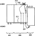
Fig. 1 is the energy band diagram of the light-emitting component of one aspect of the invention.
Fig. 2 A and 2B are the energy band diagrams of conventional light-emitting component.
Fig. 3 represents the component structure of the light-emitting component of one aspect of the invention.
Fig. 4 A and 4B represent to use the lighting device of the light-emitting component of one aspect of the invention separately.
Fig. 5 A~5C represents electronic installation separately, and described electronic installation adopts the light-emitting device of the light-emitting component that uses one aspect of the invention.
Fig. 6 A and 6B represent to use the light-emitting device of the light-emitting component of one aspect of the invention.
Fig. 7 A and 7B represent the light-emitting device of one aspect of the invention.
Fig. 8 A and 8B show light-emitting component 1 and compare the characteristic of light-emitting component 2.
Fig. 9 shows light-emitting component 1 and compares the characteristic of light-emitting component 2.
Figure 10 shows light-emitting component 1 and compares the emission spectrum of light-emitting component 2.
Figure 11 shows light-emitting component 1 and compares the brightness decay curve of light-emitting component 2.
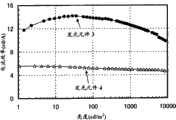
Figure 12 A and 12B show light-emitting component 3 and compare the characteristic of light-emitting component 4.
Figure 13 shows light-emitting component 3 and compares the characteristic of light-emitting component 4.
Figure 14 shows light-emitting component 3 and compares the emission spectrum of light-emitting component 4.
Figure 15 shows light-emitting component 3 and compares the brightness decay curve of light-emitting component 4.
Figure 16 shows the CV curve that measures among the embodiment 1.
The best mode that carries out an invention
Below adopt accompanying drawing that embodiments of the present invention are elaborated.It should be noted that those skilled in the art can understand the present invention at an easy rate and be not limited to following explanation and do not break away under the situation of spirit of the present invention and scope and can carry out various variations to its mode and detailed content.Therefore, explanation of the invention is not limited to the description of the following execution mode that provides.
(execution mode 1)
The notion of light-emitting component of the present invention at first, has been described in execution mode 1.It should be noted that expression has low-lying level " to have dark HOMO energy level or lumo energy " in this manual, " having shallow HOMO energy level or lumo energy " expression has high level.For example, we can say substance A-lumo energy of 2.54eV than substance B-the dark 0.26eV of lumo energy of 2.28eV, than substance C-the shallow 0.31eV of lumo energy of 2.85eV.
Recently, the inventor has been owing to the high performance cause of light-emitting component has been paid close attention to phosphorescent compound, and investigated multiple phosphorescent metal-organic complex.One of its result is, the inventor finds to compare with known phosphorescent metal-organic complex, part has dibenzo [f, h] quinoxaline skeleton and central metal be that the metal-organic complex of 9 families or 10 family's elements (hereinafter referred to as the metal-organic complex based on dibenzo [f, h] quinoxaline) can be launched phosphorescence more efficiently.
Here, can find by the evaluating characteristics that the inventor carries out, (be used as the material of luminescent layer with common material of main part, wherein be dispersed with luminescent substance) compare, above-mentioned based on dibenzo [f, h] metal-organic complex of quinoxaline has dark relatively lumo energy (that is, it has electron capture to a certain degree).On the other hand, the inventor also finds, part is conventional metal-organic complex (hereinafter referred to as " based on the metal-organic complex of pyridine ") (Ir (ppy) for example of pyridine derivate
3Or [btp
2Lr (acac)]) have shallow HOMO energy level, thereby have capturing property of high hole, to such an extent as to electronics is difficult to enter in the conventional metal-organic complex.In other words, the inventor finds, with regard to regard to the compatibility of hole and electronics, has opposite characteristic based on the metal-organic complex of dibenzo [f, h] quinoxaline with based on the metal-organic complex of pyridine.It should be noted that, in following embodiment 1, this is described.
Then, find that except advantage, also there is shortcoming in the metal-organic complex based on dibenzo [f, h] quinoxaline that shows electron capture in preparation light-emitting component process by a large amount of result of the test inventor.
One of advantage is, compares with the metal-organic complex based on pyridine of routine, is easy to accept electronics based on the metal-organic complex of dibenzo [f, h] quinoxaline, also relatively is easy to accept the hole.In other words, when being scattered in the material of main part of luminescent layer when the metal-organic complex based on dibenzo [f, h] quinoxaline, charge carrier is easy to heavily combination in based on the metal-organic complex of dibenzo [f, h] quinoxaline.Therefore, needn't note the efficient that energy shifts from material of main part, thereby can realize luminous expeditiously.
But the viewpoint of carrier balance from luminescent layer, its shortcoming are that select to be fit to material of main part based on the metal-organic complex of dibenzo [f, h] quinoxaline be unusual difficulty.This problem can be described with Fig. 2 A and 2B.
Fig. 2 A and 2B are respectively the energy band diagrams when being dispersed with luminescent layer 200 based on the metal-organic complex of dibenzo [f, h] quinoxaline in the matrix material and sandwiching in hole transmission layer 201 and the electron transfer layer 202.Fig. 2 A be will have the 1st organic compound of the hole transport ability energy band diagram during as material of main part.Fig. 2 B be will have the 2nd organic compound of the electron-transporting energy band diagram during as material of main part.
At first, in Fig. 2 A, since darker relatively based on the lumo energy 232 of the metal-organic complex of dibenzo [f, h] quinoxaline, so electronics is captured by lumo energy 232.In addition, even electronics is injected into the lumo energy 212 of the 1st organic compound, because the 1st organic compound has hole transport ability, so that electronics moves is very slow.On the other hand, because the 1st organic compound has hole transport ability, and based on dibenzo [f, h] the HOMO energy level 231 of metal-organic complex of quinoxaline do not hinder the hole (promptly, it does not form dark trap), so the hole is easy to arrive by HOMO energy level 211 near interface of electron transfer layer 202.In other words, light-emitting zone is confined to the zone that is rather narrow at interface between luminescent layer 200 and the electron transfer layer 202.
Here, shown in Fig. 2 A, if electron transfer layer 202 has the low hole closure, then the hole depends on the combination of material and arrives electron transfer layer 202.Therefore, electron transfer layer 202 may be luminous, and then reduce emitting component tempestuously.Self-evident, the inventor confirms as mentioned above, and the material that has a high hole closure when use is during as electron transfer layer 202, and the problems referred to above can be resolved, and can obtain high-luminous-efficiency, but the life-span of element is subjected to opposite influence.In addition, because the reason of triplet-triplet delustring (triplet-triplet extinction), in the anxiety of the efficient reduction of high brightness one side.
Secondly, in Fig. 2 B, owing to have dark relatively lumo energy 232 based on the metal-organic complex of dibenzo [f, h] quinoxaline, so electronics is captured by lumo energy 232.Because the 2nd organic compound has electron-transporting, so portions of electronics can be to hole transmission layer 201 1 side shiftings, and the lumo energy 222 by the 2nd organic compound gradually, thereby portions of electronics is captured.It should be noted that mobility is lower than the original electron mobility of the 2nd organic compound.On the other hand, because the 2nd organic compound has electron-transporting, so the HOMO energy level 221 of the 2nd organic compound is darker relatively, the injection difficulty in hole.Because the 2nd organic compound has electron-transporting, so even the hole is injected into, the mobility in hole is also very low.May have following situation: the hole is injected into the HOMO energy level 231 based on the metal-organic complex of dibenzo [f, h] quinoxaline, but hole transport ability is low.In other words, in the structure of Fig. 2 B, luminescent layer 200 has normal electron-transporting, but owing to be captured, electronics is difficult to move.On the other hand, the interface between hole transmission layer 210 and luminescent layer 200 is accumulated in the hole.
In the case, the interface of hole density between luminescent layer 200 and hole transmission layer 201 is high, and extremely low in other zone.On the other hand, electronics is captured based on the metal-organic complex of dibenzo [f, h] quinoxaline and is diffused to the Zone Full of luminescent layer 200, and still electron density itself is low as a complete unit.In other words, with regard to density and distribution pattern, hole distribution and electron distributions are obviously different.Therefore, be difficult to rely on the method for balance to come heavy in conjunction with hole and electronics and acquisition high-luminous-efficiency.In addition, above-mentioned imbalance produces reaction to the life-span of element.
In view of the above problems, the inventor think following some be very important.The 1st is, in the structure of Fig. 2 B, certain specific a large amount of hole is allowed to inject luminescent layer 200.The 2nd is, in the structure of Fig. 2 B, injects the hole of luminescent layer 200 and moves to electron transfer layer 202 gradually, thereby can obtain and the balance of electronics between moving gradually.Satisfy above-mentioned structure at 2 and promptly be by the structure of the present invention of energy band diagram representative as shown in Figure 1.
Luminescent layer 100 among Fig. 1 comprises the 1st organic compound with hole transport ability, the 2nd organic compound with electron-transporting and based on the metal-organic complex of dibenzo [f, h] quinoxaline.Because based on dibenzo [f, h] lumo energy 132 of metal-organic complex of quinoxaline is lower than the lumo energy 112 of the 1st organic compound and the lumo energy 122 of the 2nd organic compound, so the electronics quilt captures based on the lumo energy 132 of the metal-organic complex of dibenzo [f, h] quinoxaline.It should be noted that because the 2nd organic compound has electron-transporting, so portions of electronics can move to hole transmission layer 101 gradually, and portions of electronics is captured by the lumo energy 132 based on the metal-organic complex of dibenzo [f, h] quinoxaline.On the other hand, because the 1st organic compound has hole transport ability and hole acceptance, so the hole at first is injected into the HOMO energy level 111 of the 1st organic compound.The hole is difficult to inject the HOMO energy level 121 of the 2nd organic compound.In the case, the mobility of injected holes can be controlled by the amount of adjusting the 1st organic compound, therefore can with the movement of electrons sexual balance that is derived from electron transfer layer 102.That is, in luminescent layer 100, the balance of hole and electronics can be good.And then the hole is injected into based on the HOMO energy level 131 of the metal-organic complex of dibenzo [f, h] quinoxaline and luminous with heavy combination of the electronics that is captured.
By using above-mentioned design, the inventor finds can at utmost to be utilized based on the potentiality of the high-luminous-efficiency of the metal-organic complex of dibenzo [f, h] quinoxaline.In addition, allow the people surprised be that the inventor finds that also structure as shown in Figure 1 of the present invention can obtain the life-span than long several times to tens times of structure among Fig. 2 A and the 2B.Yet the 1st organic compound and the 2nd organic compound are used separately as main body in Fig. 2 A and 2B, and 2 types organic compound-the 1st organic compound and the 2nd organic compound are as main body in Fig. 1, and only this point is different from Fig. 2 A and 2B.Only because this point and phenomenon that the life-span extremely extends is uncommon, astonishing yet.
It should be noted that use mixed layer as luminescent layer to be increased in the life-span though patent documentation 1 has been reported, recruitment is only improved about 2 times at most, and can't obtain the life-span identical and improve effect with the present invention.According to patent documentation 1,, can reduce the electric charge accumulation that causes organic substance to decompose by the application mix layer.But, be different from the present invention, the problem of the wherein not mentioned carrier balance that causes because of electron capture based on the metal-organic complex of dibenzo [f, h] quinoxaline.Therefore in other words, patent documentation 1 and the present invention there are differences aspect the employed metal-organic complex, are using 2 types material to there are differences aspect the principle of material of main part or effect, there are differences aspect the effect thereby improve in the life-span.It should be noted that the phosphorescent compound that uses in the patent documentation 1 is the PtOEP and the [btp that belongs to based on the metal-organic complex of pyridine that belongs to porphyrin complex
2Lr (acac)], the two all has low electron capture and capturing property of high hole.That is, the phosphorescent compound that uses in the patent documentation 1 has and the opposite character of metal-organic complex based on dibenzo [f, h] quinoxaline of the present invention.
As mentioned above, with reference to energy band diagram notion of the present invention and effect have been described.More specifically structure has below been described.
(execution mode 2)
In execution mode 2, the structure of light-emitting component of the present invention is described with cited concrete material.Fig. 3 represents the structure of element.
Fig. 3 represents light-emitting component of the present invention, and described light-emitting component comprises luminescent layer 313 between as the 1st electrode 301 of anode and the 2nd electrode 302 as negative electrode.Described luminescent layer 313 comprises the 1st organic compound 321 with hole transport ability, the 2nd organic compound 322 with electron-transporting and based on the metal-organic complex 323 of dibenzo [f, h] quinoxaline.The structure of luminescent layer 313 is described at first, hereinafter.
In luminescent layer 313, the compound of the 1st organic compound 321 for having hole transport ability.Particularly, can use aromatic amine compound, such as 4,4 '-(abbreviation: NPB) of two [N-(1-naphthyl)-N-phenyl amino] biphenyl, 4,4 '-two (N-(9-phenanthryl)-N-phenyl amino] biphenyl (abbreviation: PPB), 4,4 '-(abbreviation: TPD) of two [N-(3-aminomethyl phenyl)-N-phenyl amino] biphenyl, 4,4 '-it is two that [N-(9,9-dimethyl fluorene-2-yl)-and the N-phenyl amino] biphenyl (abbreviation: DFLDPBi), 4,4 ', 4 " three (N; N-xenyl amino) triphenylamine (abbreviation: TDATA); 4; 4 '; 4 " (the abbreviation: m-MTDATA) of-three [N-(3-aminomethyl phenyl)-N-phenyl amino] triphenylamine, 4,4 ', 4 " three (N-carbazyl) triphenylamine (abbreviation: TCTA); 1; two [4-(xenyl amino) phenyl] cyclohexanes of 1-(abbreviation: TPAC); 9; two [4-(xenyl amino) phenyl] fluorenes (abbreviations: TPAF); 4-(9-carbazyl)-4 '-(5-phenyl-1 of 9-, 3,4-diazole-2-yl) triphenylamine (abbreviation: YGAO11) or N-[4-(9-carbazyl) phenyl]-N-phenyl-9,9-dimethyl fluorene-2-amine (abbreviation: YGAF); Or carbazole derivates, such as 4,4 '-two (N-carbazyl) biphenyl (abbreviation: CBP), 1, two (N-carbazyl) benzene of 3-(abbreviation: mCP) or 1,3, (the abbreviation: TCzB) of 5-three (N-carbazyl) benzene.As aromatic amine compound, also can use macromolecular compound, such as poly-(4-vinyl triphenylamine) (abbreviation: PVTPA).In addition,, also can use macromolecular compound, such as poly-(N-vinylcarbazole) (abbreviation: PVK) as carbazole derivates.It should be noted that triple excitation energy of preferred above-mentioned the 1st organic compound 321 are greater than the triple excitation energy based on the metal-organic complex 323 of dibenzo [f, h] quinoxaline.
On the other hand, the 2nd organic compound 322 is for having the compound of electron-transporting.Particularly, can use heteroaromatics, such as 9-[4-(5-phenyl-1,3,4-diazole-2-yl) phenyl] carbazole (abbreviation: CO11), 1, two [the 5-(to tert-butyl-phenyl)-1 of 3-, 3,4-diazole-2-yl] benzene (abbreviation: OXD-7), 2-(4-xenyl)-5-(4-tert-butyl-phenyl)-1,3, (the abbreviation: PBD) of 4-diazole, 2,2 ', 2 " and (1,3; 5-benzene three bases)-three (1-phenyl-1H-benzimidazole) (abbreviation: TPBI); 3-(4-tert-butyl-phenyl)-4-phenyl-5-(4-xenyl)-1; 2, (the abbreviation: TAZ); 3-(4-tert-butyl-phenyl)-4-(4-ethylphenyl)-5-(4-xenyl)-1,2; 4-triazole (abbreviation: p-EtTAZ) of 4-triazole, 9,9 ', 9 " [1,3; 5-triazine-2; 4,6-three bases] three carbazoles (abbreviation: TCzTRZ); 2,2 '; 2 "-(1,3,5-benzene three bases)-three (6,7-dimethyl-3-phenyl quinoxaline) (abbreviation: TriMeQn), 9,9 '-(quinoxaline-2,3-two bases-two-4, the 1-phenylene) two (9H-carbazoles) (abbreviation: CzQn), 3,3, ' 6,6 '-tetraphenyl-9,9 ' (quinoxaline-2,3-two bases-two-4, the 1-phenylene) two (9H-carbazoles) (abbreviation: DCzPQ), bathophenanthroline (abbreviation: BPhen), bathocuproine (abbreviation: BCP)); Metal complex, such as two (2-methyl-8-quinoline) (4-phenyl phenol) close aluminium (III) (abbreviation: BAlq), three [2-(2-hydroxy phenyl)-5-phenyl-1,3,4-diazole] close aluminium (III) (abbreviation: Al (OXD)
3), three (2-hydroxy phenyl)-1-phenyl-1H-benzimidazoles] close aluminium (III) (abbreviation: Al (BIZ)
3), two [2-(2-hydroxy phenyl) benzothiazoles] close zinc (II) (abbreviation: Zn (BTZ)
2) or two [2-(2-hydroxy phenyl) benzothiazoles] close zinc (II) (abbreviation: Zn (PBO)
2)).As heteroaromatics, also can use macromolecular compound (for example poly-(2,5-pyridine two bases) (abbreviation: PPy)).In addition, as metal complex, also can use disclosed polymer-metal complex in the list of references (: X.T.TAO etc., Applied Physics Letters, vol.70, No.12,1997, the 1503 pages the-the 1505th page).It should be noted that triple excitation energy of preferred above-mentioned the 2nd organic compound 322 are greater than the triple excitation energy based on the metal-organic complex 323 of dibenzo [f, h] quinoxaline.
Above-mentioned metal-organic complex 323 based on dibenzo [f, h] quinoxaline has dibenzo [f, h] quinoxaline skeleton for part and central metal is the metal-organic complex of 9 family's elements (Co, Rh or Ir) or 10 family's elements (Ni, Pd or Pt).In addition, above-mentioned metal-organic complex has the character of emission phosphorescence.The concrete structure of described metal-organic complex based on dibenzo [f, h] quinoxaline has been described in execution mode 3.
With above-mentioned the 1st organic compound, the 2nd organic compound and based on the suitable combination of metal-organic complex of dibenzo [f, h] quinoxaline, thereby form the luminescent layer of light-emitting component of the present invention.It should be noted that luminescent layer also can comprise other material.
Here, at least a material of main part that is used as in luminescent layer in preferred the 1st organic compound and the 2nd organic compound, and be used as guest materials based on the metal-organic complex of dibenzo [f, h] quinoxaline.This is in order to prevent the concentration quenching based on the metal-organic complex of dibenzo [f, h] quinoxaline.This also is for the carrier balance in the luminescent layer can be regulated by the 1st organic compound and the 2nd organic compound.
Therefore, in light-emitting component of the present invention, the amount of the amount of preferred the 1st organic compound and/or the 2nd organic compound is greater than the amount based on the metal-organic complex of dibenzo [f, h] quinoxaline.Particularly, preferably its volume fraction or mass fraction height.In addition, from preventing the viewpoint of concentration quenching, be preferably based on dibenzo [f, the h] metal-organic complex of quinoxaline and the ratio of luminescent layer more than or equal to 1% weight and be less than or equal to 10% weight.
In addition, in luminescent layer, the weight ratio of preferred the 1st organic compound and the 2nd organic compound is in 1: 20~20: 1 scope.That is, the weight ratio of the 2nd organic compound and the 1st organic compound is preferably greater than or equals 1/20 and be less than or equal to 20.If weight ratio is not in this scope, then the state of light-emitting component in itself can be identical with above-mentioned Fig. 2 A or 2B.
In addition, it is more effective that inventor's amount of finding to have the 2nd organic compound of electron-transporting is equal to or greater than the luminous layer structure of amount of the 1st organic compound with hole transport ability.This is seemingly because the hole mobility causes greater than electron mobility in general organic compound.Correspondingly in the present invention, the weight ratio of the 2nd organic compound and the 1st organic compound more preferably greater than or equal 1 and be less than or equal to 20.But the utmost point obtains long-life scope effectively and is preferably greater than especially or equals 5 and be less than or equal to 20.
It should be noted that the above-mentioned metal-organic complex based on dibenzo [f, h] quinoxaline that uses among the present invention has electron capture.Particularly, based on the lumo energy of the metal-organic complex of dibenzo [f, h] quinoxaline usually more than the dark 0.2eV of lumo energy than the lumo energy of the 1st organic compound and the 2nd organic compound.In addition, life-span and efficient are significantly improved in the case.Therefore, one of feature of the present invention is based on more than the dark 0.2eV of lumo energy of lumo energy than the lumo energy of the 1st organic compound and the 2nd organic compound of metal-organic complex of dibenzo [f, h] quinoxaline.
Secondly, the layer that is different from luminescent layer 313 is described.Hole transmission layer 312 and hole injection layer 311 must be provided, and can provide where necessary yet.As the concrete material that forms above-mentioned layer, preferred hole transport compound can use aforesaid NPB, PPB, TPD, DFLDPBi, TDATA, m-MTDATA, TCTA, TPAC, TPAF, YGAO11, YGAF, CBP, mCP, TCzB, PVTPA, PVK etc.
In addition, as described in enforcement mode 1,, concentrate on the interface between luminescent layer 313 and hole transmission layer 312 or the electron transfer layer 311 so can prevent light-emitting zone because luminescent layer 313 of the present invention has good carrier balance.Therefore, even triple excitation energy are lower than based on dibenzo [f, h] material of metal-organic complex 323 of quinoxaline be applied to can with luminescent layer 313 contacted hole transmission layer 312 or electron transfer layers 311, this material still is difficult to become based on dibenzo [f, h] quencher of metal-organic complex 323 of quinoxaline, thus can prepare light-emitting component with high-luminous-efficiency.Therefore, as the material that forms hole transmission layer 312 or hole injection layer 311, also can use anthracene derivant, such as 9 with low triple excitation energy, two [4-(xenyl amino) phenyl] anthracenes of 10-(abbreviation: TPA2A) or the 2-tert-butyl group-9, (the abbreviation: t-BuDNA) of 10-two (2-naphthyl) anthracene.
It should be noted that above-mentioned electron transfer layer 314 and electron injecting layer 315 can form by mixing above-mentioned electric transmission compound and electron donor.As electron acceptor, can use organic compound, such as chloranil or 7,7,8,8-four cyano-2,3,5,6-tetrafluoro dimethyl 1,4-benzoquinone (abbreviation: F4-TCNQ)), transition metal oxide (for example molybdenum oxide, vanadium oxide or rheium oxide).Particularly, also can use organic compound, such as CuPc, ranadylic phthalocyanine or fluorocarbon as hole injection layer 311; Or inorganic compound, such as molybdenum oxide, ruthenium-oxide or aluminium oxide.It should be noted that hole injection layer 311 can have the sandwich construction that forms by the layer of lamination more than 2 layers.In addition, hole injection layer 311 and hole transmission layer 312 can form by the material that mixes more than 2 kinds.
In addition, described in enforcement mode 1,, concentrate on the interface between luminescent layer 313 and electron transfer layer 314 or the electron injecting layer 315 so can prevent light-emitting zone because luminescent layer 313 of the present invention has good carrier balance.Therefore, if triple excitation energy are lower than based on dibenzo [f, h] material of metal-organic complex 323 of quinoxaline be applied to can with luminescent layer 313 contacted electron transfer layer 314 or electron injecting layers 315, then this material is difficult to become based on dibenzo [f, h] quencher of metal-organic complex 323 of quinoxaline, thus can prepare light-emitting component with high-luminous-efficiency.Therefore, the material with low triple excitation energy (can be closed aluminium (III) (abbreviation: Alq such as three (oxines)
3), three (4-methyl-oxines) close aluminium (III) (abbreviation: Almq
3) or (abbreviation: BeBq of two (10-hydroxy benzo [h] quinoline) and beryllium (II)
2) (for example, it is reported Alq as the material that forms electron transfer layer 314 or electron injecting layer 315
3Phosphorescence spectrum be the deep red of approximate 650nm~700nm).
It should be noted that above-mentioned electron transfer layer 314 and electron injecting layer 315 can form by mixing above-mentioned electric transmission compound and electron donor.As electron donor, can use the oxide of organic compound (such as tetrathiafulvalene or four sulphur aphthacenes (tetrathianaphthacene)), alkali metal (such as lithium or caesium), alkaline-earth metal (such as magnesium or calcium), rare earth metal (such as erbium or ytterbium) or above-mentioned metal.Particularly alkali metal compound, alkaline earth metal compound or rare earth compound (such as lithia, lithium fluoride, calcirm-fluoride, fluoridize erbium) can be used alone as electron injecting layer.It should be noted that electron injecting layer 315 can have the sandwich construction that forms by the layer of lamination more than 2 layers.In addition, electron transfer layer 314 and electron injecting layer 315 can form by the material that mixes more than 2 kinds.
As implement as described in the mode 2, though the 1st electrode 301 no particular restriction, when the 1st electrode 301 during as anode, preferred the 1st electrode is formed by the material with high work function.Particularly, can use material, such as the tin indium oxide (ITSO) of tin indium oxide (ITO), silicon oxide-containing or contain the indium oxide (IZO) of 2% weight~20% weight zinc oxide with high light transmittance, gold (Au), platinum (Pt), nickel (Ni), tungsten (W), chromium (Cr), molybdenum (Mo), iron (Fe), cobalt (Co), copper (Cu), palladium (Pd) etc.).It should be noted that the 1st electrode 301 can pass through for example formation such as sputtering method, evaporation.
In addition, as described in enforcement mode 2, though the 2nd electrode 302 no particular restriction, when the 2nd electrode 302 during as negative electrode, preferred the 2nd electrode is formed by the material with low work function.Particularly, can use aluminium (Al), indium (In), alkali metal (such as lithium (Li) or caesium (Cs)), alkaline-earth metal (such as magnesium (Mg) or calcium (Ca)) or rare earth metal (such as erbium (Er) or ytterbium (Yb)).Perhaps, also can use alloy, such as aluminum-copper-lithium alloys (AlLi) or magnesium-silver alloy (MgAg).In addition, when electron injecting layer 315 forms by mixed electronic transport compound and electron donor, also can use material (for example ITO, ITSO or IZO) with high work function and high light transmittance.It should be noted that the 2nd electrode 302 can pass through for example formation such as sputtering method, evaporation.
It should be noted that for the light that will produce is drawn out to the outside, side in preferred the 1st electrode 301 and the 2nd electrode 302 or two sides are the electrodes that formed by the material with high light transmittance such as ITO, ITSO or IZO.Perhaps, side in preferred the 1st electrode 301 and the 2nd electrode 302 or the two square electrodes that become thickness for a few to tens of nanometers, thus can conduct visible light.
In the light-emitting component of the invention described above, each in hole injection layer 311, hole transmission layer 312, luminescent layer 313, electron transfer layer 314 and the electron injecting layer 315 all can form by wantonly 1 method such as for example evaporation, ink-jet method or coating method etc.The 1st electrode 301 or the 2nd electrode 302 also can form by wantonly 1 method such as for example sputtering method, evaporation, ink-jet method or coating method etc.
In addition, the light-emitting component of the invention described above can be applied to tandem type light-emitting component (being also referred to as the multi-photon element).
(execution mode 3)
In the present embodiment, specifically described the metal-organic complex that can be used for light-emitting component of the present invention based on dibenzo [f, h] quinoxaline.
Metal-organic complex based on dibenzo [f, h] quinoxaline is that part has dibenzo [f, h] quinoxaline skeleton and central metal is the metal-organic complex of 9 family's elements (Co, Rh or Ir) or 10 family's elements (Ni, Pd or Pt).In addition, described metal-organic complex has the character of emission phosphorescence.
Use many metal-organic complexs of 9 families or 10 family's metals to present metal to part electric charge transfer (MLCT) transition.Particularly in phosphorescent compound, often observe triple MLCT transition.Present the lumo energy of metal-organic complex of MLCT transition by the decision of the lumo energy scope of part here.Therefore, if use the part with high lumo energy, then the lumo energy of metal-organic complex is also high, if part has low lumo energy, then the lumo energy of metal-organic complex is also low.In addition, because dibenzo [f, h] quinoxaline has the lumo energy that is lower than pyridine, so metal-organic complex based on dibenzo [f, h] quinoxaline of the present invention presents the lumo energy (being that electron capture is higher) that is lower than conventional metal-organic complex based on pyridine.
The part based on the metal-organic complex of dibenzo [f, h] quinoxaline that uses among the present invention has dibenzo [f, h] quinoxaline skeleton.As the metal-organic complex that the ortho-metalated effect by dibenzo [f, h] quinoxaline derivant obtains, for example can list following array structure formula (I) and (II) shown in metal-organic complex.


In addition, the metal-organic complex that more preferably has structure shown in following general formula (G1).Have as general formula (G1) but shown in the metal-organic complex high color purity and the red-emitting expeditiously of structure.
In the formula, Ar represents to have the aryl of 6~25 carbon atoms, R
1Expression hydrogen, have the alkyl of 1~4 carbon atom or have in the alkoxyl of 1~4 carbon atom wantonly a kind, R
2~R
8Represent hydrogen respectively, have wantonly a kind in the alkyl of 1~4 carbon atom, alkoxyl, acyloxy or the halogen group, the wantonly a kind of (R in wantonly a kind or the alkoxyl in the alkyl with 1~4 carbon atom with 1~4 carbon atom
2And R
3, R
3And R
4, R
5And R
6, R
6And R
7Or R
7And R
8In wantonly 1 pair) can mutually combine forms ring, M is a central metal, represents 9 families or 10 family's elements.
In general formula (G1), from the viewpoint of synthetic yield, R
1Be preferably hydrogen.This is owing to sterically hindered reduction, thereby makes dibenzo [f, the h] quinoxaline derivant as part easily with metal ion ortho-metalated effect take place.And, for being easy to synthesize, preferred R
2, R
4, R
5, R
7And R
8Be respectively hydrogen.As such metal-organic complex, can list metal-organic complex with structure shown in following general formula (G2).

In the formula, Ar represents to have the aryl of 6~25 carbon atoms, R
3And R
6Represent hydrogen respectively, have wantonly a kind in the alkyl of 1~4 carbon atom, the alkoxyl with 1~4 carbon atom, the acyloxy with 1~4 carbon atom or the halogen group, M is a central metal, represents 9 families or 10 family's elements.
In addition, in above-mentioned general formula (G2), owing to be easier to synthesize, so preferred R
3And R
6Be respectively hydrogen.As such metal-organic complex, can list metal-organic complex with structure shown in following general formula (G3).

In the formula, Ar represents to have the aryl of 6~25 carbon atoms, and M is a central metal, represents 9 families or 10 family's elements.
In addition, in above-mentioned general formula (G3),, can obtain the red emission of high color purity and high-luminous-efficiency by using replacement or unsubstituted phenyl as Ar.By using this metal-organic complex, can obtain to have the light-emitting component of high-luminous-efficiency.As such metal-organic complex, can list metal-organic complex with structure shown in following general formula (G4).

In the formula, R
9~R
13Represent hydrogen respectively, have wantonly a kind in the alkyl of 1~4 carbon atom, the alkoxyl with 1~4 carbon atom, the aryl with 6~12 carbon atoms or the halogen group, M is a central metal, represents 9 families or 10 family's elements.
In addition, in above-mentioned general formula (G4), preferred R
9~R
13Be respectively hydrogen.Have this structure and can obtain to have red color (that is, (x, y)=(0.67,0.33) red emission of) colourity that defines near NTSC (National Television StandardsCommittee NTSC).
It should be noted that, as having the wantonly a kind metal-organic complex in the structure shown in general formula (G1)~(G3), particularly preferred mixed ligand metal-organic complex, it is shown in wantonly a kind in the following general formula (G5)~(G8), also has ligand L outward except having dibenzo [f, h] quinoxaline derivant.This is because such complex compound is easy to synthesize.

In the formula, Ar represents to have the aryl of 6~25 carbon atoms, R
1Expression hydrogen, have the alkyl of 1~4 carbon atom or have in the alkoxyl of 1~4 carbon atom wantonly a kind, R
2~R
8Represent hydrogen respectively, have wantonly a kind in the alkyl of 1~4 carbon atom, alkoxyl, acyloxy or the halogen group, the wantonly a kind of (R in wantonly a kind or the alkoxyl in the alkyl with 1~4 carbon atom with 1~4 carbon atom
2And R
3, R
3And R
4, R
5And R
6, R
6And R
7Or R
7And R
8In wantonly 1 pair) can mutually combine forms ring, M is a central metal, represents 9 families or 10 family's elements, L represents single anion ligand, n is 2 when the center metal is 9 family elements, n is 1 when the center metal is 10 family elements.

In the formula, Ar represents to have the aryl of 6~25 carbon atoms, R
3And R
6Represent hydrogen respectively, have wantonly a kind in the alkyl of 1~4 carbon atom, alkoxyl, acyloxy or the halogen group with 1~4 carbon atom with 1~4 carbon atom, M is a central metal, represent 9 families or 10 family's elements, L represents single anion ligand, n is 2 when the center metal is 9 family elements, and n is 1 when the center metal is 10 family elements.

In the formula, Ar represents to have the aryl of 6~25 carbon atoms, and M is a central metal, represents 9 families or 10 family's elements, and L represents single anion ligand, and n is 2 when the center metal is 9 family elements, and n is 1 when the center metal is 10 family elements.

In the formula, R
9~R
13Represent hydrogen respectively, have wantonly a kind in the alkyl of 1~4 carbon atom, alkoxyl, aryl or the halogen group with 6~12 carbon atoms with 1~4 carbon atom, M is a central metal, represent 9 families or 10 family's elements, L represents single anion ligand, n is 2 when the center metal is 9 family elements, and n is 1 when the center metal is 10 family elements.
It should be noted that, in above-mentioned general formula (G8), preferred R
9~R
13Be respectively hydrogen.Have this structure and can obtain to have red color (that is, (x, y)=(0.67,0.33) red emission of) colourity that defines near NTSC (NTSC).
In addition, with regard to heavy atoms effect, the preferred iridium of central metal or the platinum of above-mentioned metal-organic complex based on dibenzo [f, h] quinoxaline.Owing to can obtain significant heavy atoms effect, thereby high efficient is provided, and also can obtain chemical stability, so preferred especially iridium.
Secondly, to aryl Ar, the substituent R in the above-mentioned general formula (G1)~(G8)
1~R
13And single anion ligand L is described in detail.
At first, as aryl Ar, the preferred aryl that uses with 6~25 carbon atoms.As the instantiation of above-mentioned aryl Ar, there are to replace or unsubstituted phenyl, 1-naphthyl, 2-naphthyl, spiral shell fluorenes-2-base, 9 9-dialkyl group fluorenes-2-base (for example 9,9-dimethyl fluorene-2-yl) etc.Particularly, can obtain to have the red emission of high color purity and high-luminous-efficiency by using replacement or unsubstituted phenyl as aryl.When above-mentioned phenyl had substituting group, more specifically described substituting group can be alkyl (for example methyl, ethyl, isopropyl or the tert-butyl group), alkoxyl (for example methoxyl group, ethyoxyl, isopropoxy or tert-butoxy), aryl (for example phenyl or 4-xenyl), halogen group (for example fluorine-based or trifluoromethyl).
Secondly, as above-mentioned substituent R
1Instantiation, comprise such as the alkyl of methyl, ethyl, isopropyl or the tert-butyl group with such as the alkoxyl of methoxyl group, ethyoxyl, isopropoxy or tert-butoxy.It should be noted that, with regard to synthetic yield, R
1Be preferably hydrogen.This is owing to sterically hindered reduction, thereby makes ligand moiety easily with metal ion ortho-metalated effect take place.
As substituent R
2~R
8Instantiation, hydrogen is arranged, such as the alkyl of methyl, ethyl, isopropyl or the tert-butyl group, such as the alkoxyl of methoxyl group, ethyoxyl, isopropoxy or tert-butoxy, such as the acyloxy of acetoxyl group with such as fluorine-based halogen group.In addition, work as R
4And R
5Mutually combine when forming ring,, methylene is arranged as instantiation.In addition, work as R
3And R
4Mutually combine and form ring and R
5And R
6Mutually combine when forming ring,, methylene-dioxy etc. is arranged as instantiation.
As substituent R
9~R
13Instantiation, hydrogen is arranged, such as the alkyl of methyl, ethyl, isopropyl or the tert-butyl group, such as the alkoxyl of methoxyl group, ethyoxyl, isopropoxy or tert-butoxy, such as the aryl of phenyl or naphthyl with such as fluorine-based halogen group.
Secondly, above-mentioned single anion ligand L is described.Above-mentioned single anion ligand L is preferably wantonly a kind in the single anion bidentate cheland that the single anion bidentate cheland with beta-diketon structure, the single anion bidentate cheland with carboxyl, the single anion bidentate cheland with phenolic hydroxyl group and 2 part elements be nitrogen.This is because above-mentioned part has high coordination ability.Although more specifically can list the single anion ligand shown in the following array structure formula (L1)~(L8), the present invention is not limited to these parts.

According to aforesaid execution mode, formed employed metal-organic complex among the present invention based on dibenzo [f, h] quinoxaline.Below enumerated concrete structural formula (following structural (1)~(56)).It should be noted that the metal-organic complex based on dibenzo [f, h] quinoxaline of the present invention is not limited to these complex compounds.


Below, the synthetic method based on the metal-organic complex of dibenzo [f, h] quinoxaline of the invention described above is described.
" synthetic method of the dibenzo shown in general formula (G0) [f, h] quinoxaline derivant "
Be to form the metal-organic complex as general formula (G1) or (G5), make dibenzo [f, the h] quinoxaline derivant shown in following general formula (G0) and the metal ion of 9 families or 10 family's elements that ortho-metalated effect take place based on dibenzo [f, h] quinoxaline.

In the formula, Ar represents to have the aryl of 6~25 carbon atoms, R
1Expression hydrogen, have the alkyl of 1~4 carbon atom or have in the alkoxyl of 1~4 carbon atom wantonly a kind, R
2~R
8Represent hydrogen respectively, have wantonly a kind in the alkyl of 1~4 carbon atom, alkoxyl, acyloxy or the halogen group, the wantonly a kind of (R in wantonly a kind or the alkoxyl in the alkyl with 1~4 carbon atom with 1~4 carbon atom
2And R
3, R
3And R
4, R
5And R
6, R
6And R
7Or R
7And R
8In wantonly 1 pair) can mutually combine forms ring.

In the formula, Ar represents to have the aryl of 6~25 carbon atoms, R
1Expression has the alkyl of 1~4 carbon atom or has in the alkoxyl of 1~4 carbon atom wantonly a kind, R
2~R
8Represent hydrogen respectively, have wantonly a kind in the alkyl of 1~4 carbon atom, alkoxyl, acyloxy or the halogen group, the wantonly a kind of (R in wantonly a kind or the alkoxyl in the alkyl with 1~4 carbon atom with 1~4 carbon atom
2And R
3, R
3And R
4, R
5And R
6, R
6And R
7Or R
7And R
8In wantonly 1 pair) can mutually combine forms ring.

In the formula, Ar represents to have the aryl of 6~25 carbon atoms, R
2~R
8Represent hydrogen respectively, have wantonly a kind in the alkyl of 1~4 carbon atom, alkoxyl, acyloxy or the halogen group, the wantonly a kind of (R in wantonly a kind or the alkoxyl in the alkyl with 1~4 carbon atom with 1~4 carbon atom
2And R
3, R
3And R
4, R
5And R
6, R
6And R
7Or R
7And R
8In wantonly 1 pair) can mutually combine forms ring.
At first, the dibenzo shown in general formula (G0-1) [f, h] quinoxaline derivant can be synthetic by simple synthetic route as follows.For example, shown in following route (a), the dibenzo shown in general formula (G0-1) [f, h] quinoxaline derivant can obtain by diaminourea phenanthrene compound (A1) and dione compounds (A2) reaction.

On the other hand, the dibenzo shown in general formula (G0-2) [f, h] quinoxaline derivant can be synthetic according to simple synthetic route as follows.For example, shown in following route (a '), the dibenzo shown in general formula (G0-2) [f, h] quinoxaline derivant can obtain by diaminourea phenanthrene compound (A1 ') and dione compounds (A2 ') reaction.Perhaps, as following route (shown in a "); make dione compounds (A1 ") and diamine compound (A2 ") reaction generate dibenzo [f; h] quinoxaline derivant (G0-2 '); and then make dibenzo [f; h] quinoxaline derivant (G0-2 ') and aryl lithium or aryl bromination magnesium compound (A3) reaction that as above obtains, thus dibenzo [f, the h] quinoxaline derivant of acquisition shown in general formula (G0-2).

As above-claimed cpd (A1), (A2), (A1 '), (A2 '), (A1 "), (A2 ") with (A3), can buy or synthetic multiple compound.Therefore, in the dibenzo shown in above-mentioned general formula (G0) [f, h] quinoxaline derivant, there are many mutation that can be synthesized.
" synthetic method " with metal-organic complex of structure shown in general formula (G1)
Secondly, to the metal-organic complex that the ortho-metalated effect by the dibenzo shown in general formula (G0) [f, h] quinoxaline derivant forms, the metal-organic complex that promptly has structure shown in following general formula (G1) is described.

In the formula, Ar represents to have the aryl of 6~25 carbon atoms, R
1Expression hydrogen, have the alkyl of 1~4 carbon atom or have in the alkoxyl of 1~4 carbon atom wantonly a kind, R
2~R
8Represent hydrogen respectively, have wantonly a kind in the alkyl of 1~4 carbon atom, alkoxyl, acyloxy or the halogen group, the wantonly a kind of (R in wantonly a kind or the alkoxyl in the alkyl with 1~4 carbon atom with 1~4 carbon atom
2And R
3, R
3And R
4, R
5And R
6, R
6And R
7Or R
7And R
8In wantonly 1 pair) can mutually combine forms ring, M is a central metal, represents 9 families or 10 family's elements.
At first, shown in following synthetic route (b), dibenzo [f that will be shown in general formula (G0), h] quinoxaline derivant and 9 families or the 10 family's metallic compounds (for example metal halide or metal complex) that contain halogen heat in suitable solvent, generation belongs to the dinuclear complex (B) of one of form of metal-organic complex of the present invention, and described complex compound has the structure shown in general formula (G1).As 9 families of containing halogen or 10 family's metallic compounds, have radium chloride hydrate, palladium bichloride, inidum chloride hydrate, chlorination of hydrochloric acid iridium hydrate (iridium chloridehydrochloride hydrate), tetrachloro to close the sour potassium of platinum (II) etc., but the present invention is not limited to above-mentioned example.It should be noted that in synthetic route (b), M represents 9 families or 10 family's elements, X represents halogen.In addition, n is 2 when M is 9 family elements, and n is 1 when M is 10 family elements.

In addition, shown in following synthetic route (c), under near 200 ℃ high temperature with above-mentioned dinuclear complex (B) and the dibenzo [f shown in general formula (G0), h] quinoxaline derivant heats in high boiling solvent (for example glycerine), thus can obtain to have a kind of form (C) of the metal-organic complex of the present invention of structure shown in general formula (G1).Perhaps, shown in following synthetic route (c '), under near 200 ℃ high temperature with dinuclear complex (B) and (more generally such as the compound that ortho-metalated effect takes place of phenylpyridine, but heating in high boiling solvent (for example glycerine) compound of initial ring metalation), thereby can obtain to have a kind of form (C ') of the metal-organic complex of the present invention of structure shown in general formula (G1).It should be noted that in synthetic route (c) and (c '), M represents 9 families or 10 family's elements, X represents halogen.In addition, n is 2 when M is 9 family elements, and n is 1 when M is 10 family elements.


" synthetic method " with metal-organic complex of structure shown in general formula (G5)
Here, the metal-organic complex shown in following general formula (G5) is described, described complex compound is the preferred embodiment with above-mentioned metal-organic complex of structure shown in general formula (G1).

In the formula, Ar represents to have the aryl of 6~25 carbon atoms, R
1Expression hydrogen, have the alkyl of 1~4 carbon atom or have in the alkoxyl of 1~4 carbon atom wantonly a kind, R
2~R
8Represent hydrogen respectively, have wantonly a kind in the alkyl of 1~4 carbon atom, alkoxyl, acyloxy or the halogen group, the wantonly a kind of (R in wantonly a kind or the alkoxyl in the alkyl with 1~4 carbon atom with 1~4 carbon atom
2And R
3, R
3And R
4, R
5And R
6, R
6And R
7Or R
7And R
8In wantonly 1 pair) can mutually combine forms ring, M is a central metal, represents 9 families or 10 family's elements, L represents single anion ligand, n is 2 when the center metal is 9 family elements, n is 1 when the center metal is 10 family elements.
Metal-organic complex of the present invention shown in above-mentioned general formula (G5) can (c ") be synthetic according to following synthetic route.In other words, make the dinuclear complex (B) that obtains by said synthesis route (b) and as the HL reaction of single anion ligand L material, thereby the proton that makes HL is removed and coordination is incorporated into central metal M, generates the metal-organic complex of the present invention shown in general formula (G5).It should be noted that (among the c "), M represents 9 families or 10 family's elements, and X represents halogen in synthetic route.In addition, n is 2 when M is 9 family elements, and n is 1 when M is 10 family elements.


As mentioned above, can synthesize the metal-organic complex that is used for light-emitting component of the present invention based on dibenzo [f, h] quinoxaline.
(execution mode 4)
In execution mode 4, the example as the light-emitting device with light-emitting component of the present invention is described image display device.
In this execution mode, adopt Fig. 6 A and 6B that the image display device that has light-emitting component of the present invention in the pixel portions is described.It should be noted that Fig. 6 A is the vertical view of explanation light-emitting device, and Fig. 6 B is along line A-A ' among Fig. 6 A and the sectional view of B-B '.Described image display device comprises and is used to control the luminous drive circuit portion of light-emitting component (source side drive circuit) 601, pixel portions 602 and drive circuit portion (gate side drive circuit) 603 that they dot.In addition, reference number 604 expression seal substrate, reference number 605 expression encapsulants.The part that sealed material 605 is surrounded is space 607.
It should be noted that, the line 608 that leads is the wiring lines that are used to transmit by source side drive circuit 601 and 603 inputs of gate side drive circuit, and from as flexible print circuit (FPC) 609 receiving video signals of external input terminals, clock signal, initial signal, reset signal etc.It should be noted that though only show FPC herein, this FPC can have printed substrate (PWB).It should be noted that the light-emitting device in this specification not only comprises light-emitting device itself, but also comprise the light-emitting device that is attached with FPC or PWB.
Below, adopt Fig. 6 B pair cross-section structure to be described.Though drive circuit portion and pixel portions are provided on component substrate 610, the source side drive circuit 601 of drive circuit portion and a pixel of pixel portions 602 only are shown here.
It should be noted that form cmos circuit as source side drive circuit 601, described cmos circuit is the combination of n channel-type TFT623 and p channel-type TFT624.In addition, the TFT that is used to form drive circuit portion can be wantonly a kind in the multiple circuit, for example known cmos circuit, PMOS circuit or nmos circuit.In addition, in the present embodiment, though described drive circuit is formed on driver integrated-type structure on the substrate, drive circuit might not be formed on the substrate, also can be formed on the substrate outside.
In addition, pixel portions 602 is made up of a plurality of pixels, and each pixel comprises that all switching TFT 611, Current Control TFT612 and conduct are electrically connected to the 1st electrode 613 of the drain electrode of Current Control TFT612.It should be noted that, form insulator 614 to cover the marginal portion of the 1st electrode 613.Here, insulant 614 adopts the positive photosensitive acrylic resin film to form.
In addition, for improving spreadability, form curved surface with curvature in the upper end or the bottom of insulant 614.For example, when using the positive photosensitive acrylic resin, only preferably insulator 614 is shaped to the curved surface that part in the top has radius of curvature (0.2 μ m~3 μ m) as the material of insulator 614.In addition, the positive photosensitive material that is insoluble to the minus light-sensitive material of etchant or dissolves in etchant because of illumination because of illumination all can be used for this insulator 614.
On the 1st electrode 613, be formed with layer the 616 and the 2nd electrode 617 that comprises luminescent layer.As the material that is used for the 1st electrode 613, can use wantonly a kind in multiple metal, alloy or conductive compound or its mixture here.When the 1st electrode 613 is used as anode, in above-mentioned material, preferably use metal, alloy or conductive compound, its mixture etc. to have in the material of high work function (work function is as more than the 4.0eV) wantonly a kind.For example, can use the monofilm of siliceous indium oxide-tin oxide film, indium oxide-Zinc oxide film, titanium nitride film, chromium film, tungsten film, Zn film, Pt film etc., titanium nitride film and contain the laminated film of aluminium as the film of main component, contains aluminium as the film of main component and the three-decker of titanium nitride film etc. at titanium nitride film.It should be noted that when adopting laminar structure, the resistance of wiring is low, form good Ohmic contact, and the 1st electrode 613 can be brought into play function as anode.
In addition, comprising the layer 616 of luminescent layer can be by the wantonly a kind of formation in the several different methods (for example using the evaporation, ink-jet method, spin-coating method of evaporation mask etc.).The layer 616 that comprises luminescent layer has the luminescent layer of wantonly 1 description in the execution mode 1~3.In addition, the material that is used to comprise the layer 616 of luminescent layer can be low molecular material, medium molecule material (this type of comprises oligomer and dendrimer) or macromolecular material with the character between macromolecular material and low molecular material.Perhaps, the material as the layer that is used to comprise luminescent layer not only can use organic compound, also can use inorganic compound.
In addition, as the material that is used for the 2nd electrode 617, can use wantonly a kind in multiple metal, alloy or conductive compound or its mixture.When the 2nd electrode 617 is used as negative electrode, in above-mentioned material, preferably use metal, alloy or conductive compound, its mixture etc. to have the material of low work function (work function is following as 3.8eV).For example, alkali metal (for example lithium (Li) and caesium (Cs)) and alkaline-earth metal (for example magnesium (Mg), calcium (Ca) and strontium (Sr)) etc. be can list and the element of 1 and 2 families in the periodic table and alloy thereof etc. belonged to.It should be noted that, when the light that produces in the layer 616 that comprises luminescent layer transmits by the 2nd electrode 617, also can be with laminated film as the 2nd electrode 617, described laminated film has the metallic film of low thickness and nesa coating (indium oxide-tin oxide (ITO), the indium oxide-tin oxide that contains silicon or silica, indium oxide-zinc oxide (IZO), contain the indium oxide (IWZO) of tungsten oxide and zinc oxide etc.).
In addition, also provide and used encapsulant 605 that seal substrate 604 is attached to the structure of component substrate 610, thereby light-emitting component 618 has been arranged in the space 607 that is formed by component substrate 610, seal substrate 604 and encapsulant 605 encirclements.It should be noted that space 607 is full of filler.Comprise following situation: space 607 is full of inert gas (nitrogen, argon etc.), and space 607 can be full of encapsulant 605.
It should be noted that, preferably use epoxy resin as encapsulant 605.In addition, preferred above-mentioned material conducting water or oxygen hardly.In addition, as seal substrate 604, except glass substrate, quartz substrate, can also use the plastic that forms by fiberglass reinforced plastics (FRP), polyvinyl fluoride (PVF), polyester, acrylic resin etc.
As mentioned above, can obtain to have the active array type light-emitting device of light-emitting component of the present invention.
Though up to the present described the active array type image display device that passes through the driving of transistor controls light-emitting component therein, but described image display device also can be a passive, and wherein said light-emitting component is driven under the situation of no specific driving element (for example transistor).Fig. 7 A and 7B are perspective view and the sectional views that adopts the passive matrix light-emitting device of light-emitting component of the present invention.In Fig. 7 A and 7B, place between electrode 952 and the electrode 956 at the layer 955 that will comprise luminescent layer on the substrate 951.The marginal portion of electrode 952 is covered by insulating barrier 953.In addition, separate layer 954 is set on insulating barrier 953.The sidewall slope of separate layer 954 is so that along with the surface of sidewall near substrate, the distance between a sidewall and another sidewall narrows down.In other words, separate layer 954 is trapezoidal along the cross section of short side direction, and the trapezoidal end (in trapezoidal parallel and with insulating barrier 953 contacted sides) with insulating barrier 953 surface be shorter than trapezoidal upside (in trapezoidal parallel with insulating barrier 953 surfaces but not with insulating barrier 953 contacted sides).The adding of separate layer 954 can prevent luminescent layer because static etc. is former thereby have a defective in the present embodiment.
As mentioned above, because the image display device of describing in the execution mode 4 of the present invention has the light-emitting component of the present invention of wantonly 1 description in the execution mode 1~3, so this image display device has high-luminous-efficiency and long-life.Therefore, adopt the image display device consume low power of light-emitting component of the present invention and having the long-life.
It should be noted that, execution mode 4 can with other wantonly 1 execution mode appropriate combination.
(execution mode 5)
Because light-emitting component of the present invention has high-luminous-efficiency and long-life, so light-emitting component of the present invention can be used to belong to the lighting device of one of example of light-emitting device.Correspondingly in execution mode 5, the application example of the lighting device that uses light-emitting component of the present invention is described.
Fig. 4 A shows the example of liquid crystal indicator, in the described liquid crystal indicator light-emitting component of the present invention is used as backlight.Liquid crystal indicator shown in Fig. 4 A comprises framework 401, liquid crystal layer 402, backlight 403 and framework 404.Liquid crystal layer 402 is connected to drive IC 405.In addition, light-emitting component of the present invention is used for backlight 403,406 electric current is offered backlight 403 by going between.
By with the backlight of light-emitting component of the present invention, can obtain to have high-luminous-efficiency and long-life backlight as liquid crystal indicator.In addition, can realize having long-life backlight.In addition, be the lighting device of plane of departure light owing to use the backlight of light-emitting component of the present invention, and can form large tracts of land, thus can be made into bigger backlight, and liquid crystal indicator also can have bigger area.In addition, because light-emitting device is thin and consume low power, so can reduce the thickness and the power consumption of display unit.
Fig. 4 B shows the example that will use the lighting device of light-emitting component of the present invention as the desk lamp light source.Desk lamp shown in Fig. 4 B comprises framework 411 and light source 412.As light source 412, use light-emitting component of the present invention.Because light-emitting component of the present invention has the long-life, so above-mentioned desk lamp also can have the long-life.
The lighting device of describing in the execution mode 5 of the present invention has the light-emitting component of the present invention of wantonly 1 description in the execution mode 1~3.Therefore, described lighting device has high-luminous-efficiency and long-life.Therefore, use the lighting device consume low power of light-emitting component of the present invention and having the long-life.
(execution mode 6)
As implement the image display device of the present invention described in the mode 4 and can show excellent image.Therefore, by image display device of the present invention being applied to the display part of electronic installation, can obtain to provide the electronic installation of excellent image.In addition, comprise the image display device of light-emitting component of the present invention or lighting device (being light-emitting device) consume low power and have the long-life.Therefore, by light-emitting device of the present invention being applied to the display part of electronic installation, can obtain to have the electronic installation of low-power consumption.For example, can obtain phone etc. and have electronic installation of long battery duration etc.Hereinafter the electronic installation example with light-emitting device of using light-emitting component of the present invention is described.
Fig. 5 A shows by using the computer that the present invention makes, and described computer comprises main body 511, framework 512, display part 513, keyboard 514 etc.Be applied to display part by the light-emitting device that will have light-emitting component of the present invention, can finish the aforementioned calculation machine.
Fig. 5 B shows by using the phone that the present invention makes, wherein main body 522 comprise that display part 521, audio output part divide 524, audio frequency importation 525, console switch 526 and 527, antenna 523 etc.Be applied to display part by the light-emitting device that will have light-emitting component of the present invention, can finish above-mentioned phone.
Fig. 5 C shows by using the television set that the present invention makes, and described television set comprises display part 531, framework 532, loud speaker 533 etc.Be applied to display part by the light-emitting device that will have light-emitting component of the present invention, can finish above-mentioned television set.
As mentioned above, light-emitting device of the present invention is suitable as the display part of various electronic installations very much.
It should be noted that though described computer etc. in execution mode 6, the light-emitting device that comprises light-emitting component of the present invention also can be installed on navigation system, lighting apparatus etc.
[embodiment 1]
In embodiment 1, electron capture to the metal-organic complex that can be used for light-emitting component of the present invention is estimated, described metal-organic complex is that part has dibenzo [f, h] quinoxaline skeleton and central metal be the metal-organic complex (based on the metal-organic complex of dibenzo [f, h] quinoxaline) of 9 families or 10 family's elements.
For estimating,, obtain lumo energy according to evaluation result then by the reduction reaction characteristic of annular volt-ampere (CV) mensuration mensuration based on the metal-organic complex of dibenzo [f, h] quinoxaline.In addition, adopt similar method to obtain usually lumo energy, compare with lumo energy then based on the metal-organic complex of dibenzo [f, h] quinoxaline as the substrate of material of main part.It should be noted that, use electrochemical analyzer (ALS model600A or 600C, BAS Inc. system) to carry out said determination.
As the solution that is used for the CV determination method, the dimethyl formamide (DMF, Sigma-Aldrich Inc. system, 99.8%, catalog number (Cat.No.) 22705-6) that uses dehydration will be as the tetra n butyl ammonium perchlorate (n-Bu of supporting electrolyte as solvent
4NC10
4, Tokyo Chemical IndustryCo., Ltd. system, catalog number (Cat.No.) T0836) be dissolved in the above-mentioned solvent, make that the concentration of TBAP is 100mmol/L.In addition, determination object is also dissolved, making its concentration is 2mmol/L.In addition, as work electrode, use platinum electrode (PTE platinum electrode, BAS Inc. system).As auxiliary electrode, use platinum electrode (VC-3Pt to electrode (5cm), BAS Inc. system).As reference electrode, use Ag/Ag
+Electrode (RE7 nonaqueous solvents reference electrode, BAS Inc. system).It should be noted that said determination carries out under room temperature (20 ℃~25 ℃).Sweep speed during in addition, with enforcement CV determination method is fixed as 0.1V/ second.
(calculating of the electrical potential energy of reference electrode under vacuum)
At first, to employed reference electrode (Ag/Ag in this enforcement
+Electrode) electrical potential energy under vacuum (eV) is calculated.That is, to Ag/Ag
+The Fermi level of electrode calculates.With regard to standard hydrogen electrode, the oxidation-reduction potential of known ferrocene in methyl alcohol is+0.610[V, with respect to SHE] (list of references: Christian R.Goldsmith etc., J.Am.Chem.Soc, Vol.124, No.1, the 83rd page the-the 96th page, 2002).On the other hand, by using the reference electrode that is adopted in the present embodiment, calculate the oxidation-reduction potential of ferrocene in methyl alcohol and be+0.11[V, with respect to Ag/Ag
+].Therefore, find that the electrical potential energy of employed reference electrode among the embodiment 1 is than the low 0.50[eV of standard hydrogen electrode].
Here, the electrical potential energy of known standard standard hydrogen electrode under vacuum is-4.44eV (list of references: Toshihiro Ohnishi and Tamami Koyama, High Molecular ELMaterial, Kyoritsu Shuppan, 64-67 page or leaf).Correspondingly, the electrical potential energy of the employed reference electrode of present embodiment under vacuum can followingly be calculated :-4.44-0.50=-4.94[eV].
(measure routine: structural formula (1))
At first, in this mensuration example, with the Ir (dbq-P) shown in the structural formula (1)
2(acac) be example, the calculating of the lumo energy that adopts the CV determination method is described in detail.Figure 16 has shown the CV measurement result of reduction reaction characteristic.It should be noted that, the mensuration of reduction reaction characteristic by earlier-1.35V~-scope of 2.30V in and subsequently-2.30V~-the scope interscan work electrode of 1.35V carries out with respect to the current potential of reference electrode.
As shown in figure 16, reduction spike potential E
PcFor-1.78V.In addition, oxidation spike potential E
PaFor-1.67V.Correspondingly, can calculate half wave potential (E
PcAnd E
PaIntermediate potential) be-1.72V.The above results shows Ir (dbq-P)
2(acac) can be by-1.72[V, with respect to Ag/Ag
+] electric energy reduce, this energy is corresponding to lumo energy.Here, as mentioned above among the embodiment 1 electrical potential energy of employed reference electrode under vacuum be-4.94[eV].Therefore, the lumo energy based on the metal-organic complex of dibenzo [f, h] quinoxaline shown in structural formula (1) can followingly calculate :-4.94-(1.72)=-3.22[eV].
(summary of measurement result)
Adopt similar method to measure the lumo energy described in the execution mode 3 based on the metal-organic complex of dibenzo [f, h] quinoxaline.In addition, also measure as a reference as the lumo energy of the electric transmission compd B Alq (shown in the following array structure formula (i)) that is widely used as the material of main part of red phosphorescent compound.

Under tabulate and the result summarized in 1.As shown in Table 1, have darker lumo energy based on the metal-organic complex of dibenzo [f, h] quinoxaline, its lumo energy is greater than-2.7eV.In addition, the lumo energy of finding above-mentioned metal-organic complex based on dibenzo [f, h] quinoxaline dark than BAlq.Therefore, the result of embodiment 1 shows that employed metal-organic complex based on dibenzo [f, h] quinoxaline has high relatively electron capture among the present invention.
[table 1]
Structural formula substrate E1/2 lumo energy
(No.) (abbreviation) [V is with respect to Ag/Ag
+] [eV]
(1)??????Ir(dbq-P)
2(acac)?????-1.72??????????????-3.22
(55)?????Ir(dbq-3FP)
2(acac)???-1.65??????????????-3.29
(i)??????BAlq?????????????????-2.32??????????????-2.62
[embodiment 2]
In embodiment 2, illustrate light-emitting component of the present invention clearly by contrast with comparative example.It should be noted that, in the present embodiment molecular structure of employed material as (ii) following and (iii) shown in.In addition, Fig. 3 shows the structure of described element.

" preparation of light-emitting component 1 and light-emitting component 2 "
At first, preparation is as the glass substrate of anode, and depositing thickness on the described glass substrate is the indium tin Si oxide (ITSO) of 110nm.Thereby the marginal surface of above-mentioned ITSO covers with polyimide film and exposes the surface that area is 2mm * 2mm.Electrode area is set at 2mm * 2mm.As the preliminary treatment that on above-mentioned substrate, forms described light-emitting component, wash the surface of above-mentioned substrate with water, toasted 1 hour down in 200 ℃, implemented the UV ozone treatment then 370 seconds.Then, above-mentioned substrate-transfer to pressure is reduced to about 10
-4In the vacuum deposition apparatus of Pa, in the heating chamber of vacuum deposition apparatus,, above-mentioned substrate is cooled off about 30 minutes then in 170 ℃ of following vacuum bakeouts 30 minutes.
Then, substrate is fixed on the support that is arranged in the vacuum deposition apparatus, make have ITSO substrate surface down.
Pressure in the vacuum evaporation coating device reduces to 10
-4Behind the Pa, be total to NPB and the molybdenum oxide (VI) shown in the evaporation structural formula (i), the weight ratio that makes NPB and molybdenum oxide (VI) is 4: 1, thereby forms hole injection layer 311.The thickness of described hole injection layer 311 is set to 50nm.It should be noted that described evaporation altogether is meant the evaporation coating method that evaporates multiple different material from different evaporation sources simultaneously.Then, be that 10nm is thick in to form hole transmission layer 312 with the NPB evaporation.
In addition, forming thickness on above-mentioned hole transmission layer 312 is the luminescent layer 313 of 50nm.Light-emitting component 1 is following light-emitting component of the present invention, in this light-emitting component with NPB as the 1st organic compound, with the BAlq shown in the structural formula (i) among the embodiment 1 as the 2nd organic compound and with the Ir (dpq-P) shown in the structural formula (1) in the execution mode 3
2(acac) as metal-organic complex based on dibenzo [f, h] quinoxaline.With regard to above-mentioned light-emitting component 1, above-mentioned material is carried out common evaporation, make NPB: BAlq: Ir (dpq-P)
2(acac) weight ratio is 0.05: 1: 0.06, thereby forms luminescent layer 313.On the other hand, with regard to the light-emitting component 2 of light-emitting component in contrast,, only use BAlq and do not use NPB as material of main part.With regard to light-emitting component 2, above-mentioned material is carried out common evaporation, make BAlq: Ir (dpq-P)
2(acac) weight ratio is 1: 0.06, thereby forms luminescent layer 313.
Then, be that 30nm is thick with the Alq evaporation of structural formula shown in (iii), thereby form electron transfer layer 314.In addition, lithium fluoride is deposited as 1nm on above-mentioned electron transfer layer 314 thick, thereby form electron injecting layer 315.At last, be that 200nm is thick in to form the 2nd electrode 302 as negative electrode with al deposition.Correspondingly prepare light-emitting component 1 and 2.It should be noted that,, adopt electrical resistance heating for above-mentioned wantonly 1 evaporation process.
" operating characteristic of light-emitting component 1 and light-emitting component 2 "
In the glove box of nitrogen atmosphere, encapsulate, thereby the light-emitting component 1 and 2 that as above obtains is not exposed in the atmosphere, then the operating characteristic of above-mentioned light-emitting component is measured.It should be noted that said determination carries out under room temperature (remaining 25 ℃ in atmosphere).
Current density contrasts the light characteristic of above-mentioned light-emitting component shown in Fig. 8 A, and its light characteristic of voltage-contrast is shown in Fig. 8 B.In addition, the current efficiency characteristic of the above-mentioned light-emitting component of brightness contrast as shown in Figure 9.In addition, the emission spectrum of above-mentioned light-emitting component as shown in figure 10.The emission spectrum of above-mentioned light-emitting component is basic identical, and luminous color is for being derived from Ir (dbq-P)
2(acac) redness.
As shown in Figure 9, the current efficiency of the light-emitting component 2 of light-emitting component is extremely low as a comparison, and its current efficiency is less than or equal to half of current efficiency of light-emitting component 1 of the present invention.Above-mentioned light-emitting component 2 is in the shown state of Fig. 2 B in the execution mode 1.Owing to will have the Ir (dbq-P) of high electron capture
2(acac) among the BAlq of adding as the electric transmission compound, so think that carrier balance is poor, current efficiency reduces.In addition, shown in Fig. 8 B, the driving voltage height.
On the other hand, as shown in Figure 9, light-emitting component 1 of the present invention demonstrates high-luminous-efficiency.
Secondly, original intensity is set to 1000cd/m
2, under constant current density, drive said elements then, thereby obtain brightness decay curve as shown in figure 11.In Figure 11, transverse axis express time, the longitudinal axis are represented the relative brightness (%) when initial brightness is 100.As shown in figure 11, light-emitting component of the present invention also has the life-span of greatly being improved.
Here, 1000cd/m
2Under characteristic and the life-span be compared as follows the tabulation 2 shown in.It should be noted that, as shown in figure 11 since can expect light-emitting component 1 experience 100,000 hours with on reach the brightness half-life, so reduce the life-span of 10% needed time comparison said elements according to brightness.
[table 2]
(characteristic among the embodiment 2)
| Voltage [V] | Current efficiency [cd/A] | External quantum efficiency [%] | Power efficiency [1m/W] | 10% brightness reduces the time [hr] | |
| Light-emitting |
??8.8 | ??16 | ??14 | ??5.7 | ??201 |
| Light-emitting |
??9.2 | ??7 | ??6.0 | ??2.4 | ??19.8 |
At first, as shown in table 2, only use BAlq extremely low, and use NPB and these 2 kinds of materials of BAlq are as current efficiency, external quantum efficiency and the power efficiency height of the light-emitting component 1 of material of main part as current efficiency, external quantum efficiency and the power efficiency of the light-emitting component 2 of material of main part.The above results can not be expected by the NPB of independent use or the character of BAlq.This is equally applicable to the life-span, and the brightness half-life of light-emitting component 1 is estimated about more than 50,000 hours.
As mentioned above, find to obtain high-luminous-efficiency and long-life simultaneously by preparing light-emitting component of the present invention.Therefore, can obtain to have the high-luminous-efficiency and the light-emitting component in elongate elements life-span by finishing the present invention.
" preparation of light-emitting component 3 and light-emitting component 4 "
Except using Ir (dbq-3FP)
2(acac) (shown in the structural formula in the enforcement mode 3 (55)) replaces the Ir (dbq-P) of luminescent layer 313
2(acac) outside, adopt the method identical to prepare light-emitting component 3 of the present invention with light-emitting component 1.In addition, except using Ir (dbq-3FP)
2(acac) Ir (dbq-P) of replacement luminescent layer 313
2(acac) outside, adopt the method identical to prepare the light-emitting component 4 of light-emitting component as a comparison with light-emitting component 2.
" operating characteristic of light-emitting component 3 and light-emitting component 4 "
In the glove box of nitrogen atmosphere, encapsulate, thereby the light-emitting component 3 and the light-emitting component 4 that as above obtain are not exposed in the atmosphere, then the operating characteristic of above-mentioned light-emitting component is measured.It should be noted that said determination carries out under room temperature (remaining 25 ℃ in atmosphere).
Current density contrasts the light characteristic of above-mentioned light-emitting component shown in Figure 12 A, and its light characteristic of voltage-contrast is shown in Figure 12 B.In addition, the current efficiency characteristic of the above-mentioned light-emitting component of brightness contrast as shown in figure 13.In addition, the emission spectrum of above-mentioned light-emitting component as shown in figure 14.The emission spectrum of above-mentioned light-emitting component is basic identical, and luminous color is for being derived from Ir (dbq-3FP)
2(acac) redness.
As shown in figure 13, the current efficiency of the light-emitting component 4 of light-emitting component is extremely low as a comparison, and its current efficiency is less than or equal to half of current efficiency of light-emitting component 3 of the present invention.Above-mentioned light-emitting component 4 is in the shown state of Fig. 2 B in the execution mode 1.Owing to will have the Ir (dbq-3FP) of high electron capture
2(acac) among the BAlq of adding as the electric transmission compound, so think that carrier balance is poor, current efficiency reduces.In addition, shown in Figure 12 B, luminous starting voltage height.
On the other hand, as shown in figure 13, light-emitting component 3 of the present invention demonstrates high-luminous-efficiency.
Secondly, original intensity is set to 1000cd/m
2, under constant current density, drive said elements then, thereby obtain brightness decay curve as shown in figure 15.In Figure 15, transverse axis express time, the longitudinal axis are represented the relative brightness (%) when initial brightness is 100.As shown in figure 15, light-emitting component of the present invention also has the life-span of greatly being improved.
Here, 1000cd/m
2Under characteristic and the life-span be compared as follows the tabulation 3 shown in.It should be noted that, as shown in figure 15 since can expect light-emitting component 3 experience 10,000 hours with on reach the brightness half-life, so reduce the life-span of 10% needed time comparison said elements according to brightness.
[table 3]
(characteristic among the embodiment 2)
| Voltage [V] | Current efficiency [cd/A] | External quantum efficiency [%] | Power efficiency [lm/W] | 10% brightness reduces the time [hr] | |
| Light-emitting component 3 | ??11 | ??13 | ??13 | ??3.6 | ??241 |
| Light-emitting |
??10 | ??5.0 | ??5.0 | ??1.5 | ??48.2 |
At first, use NPB and these 2 kinds of materials of BAlq current efficiency, external quantum efficiency and power efficiency height, and only use BAlq extremely low as current efficiency, external quantum efficiency and the power efficiency of the light-emitting component 4 of material of main part as the light-emitting component 3 of material of main part.The above results can not be expected by the NPB of independent use or the character of BAlq.This is equally applicable to the life-span, and the estimation of the brightness half-life of light-emitting component 3 is about 20,000 hours.
As mentioned above, find to obtain high-luminous-efficiency and long-life simultaneously by preparing light-emitting component of the present invention.Therefore, can obtain to have the high-luminous-efficiency and the light-emitting component in elongate elements life-span by finishing the present invention.
Here, to as the Ir (dbq-P) that is used for above-mentioned light-emitting component based on the metal-organic complex of dibenzo [f, h] quinoxaline
2(acac) and Ir (dbq-3FP)
2(acac) synthetic method is described.
" (acetylacetone,2,4-pentanedione) two (2-phenyl dibenzo [f, h] quinoxalines) close iridium (III) (abbreviation: Ir (dbq-P)
2(acac) synthetic method) "
[step 1:2-phenyl dibenzo [f, h] quinoxaline (abbreviation: Hdbq-P) synthetic]
At first, with 9 of the phenylglyoxal of 2.16g and 3.36g, 10-diaminourea phenanthrene is dissolved in the dewatered ethanol of 100mL under blanket of nitrogen.The solution backflow was made it reaction in 7 hours.Filtration is by the white powder of reaction precipitation.Residue is successively used the washing of ethanol and ether, thereby make dibenzo [f, h] quinoxaline derivant Hdbq-P (productive rate: 92%) as object.The synthetic route of step 1 is shown in following (a-1).

[step 2: two-μ-chloro-two [two (2-phenyl dibenzo [f, h] quinoxalines) close iridium (III)] (abbreviation: [Ir (dbq-P)
2Cl]
2) synthetic]
Follow above-mentioned steps 1, with the cellosolvo of 24mL, the water of 8mL, dibenzo [f, h] the quinoxaline derivant Hdbq-P that in above-mentioned steps 1, obtains of 0.61g and the iridium chloride hydrate (IrCl of 0.30g
3H
2O) (Sigma-Aldrich Corp. system) places the recovery flask with return duct.With the air in the argon displacement flask.Then, (2.45GHz, 200W) irradiation is 5 hours, makes it reaction with microwave with mixture.The orange powder that filtration precipitates from reactant liquor washs residue with ethanol, thereby makes dinuclear complex [Ir (dbq-P)
2Cl]
2(productive rate: 78%).It should be noted that, microwave synthesis system (Discovery, CEMCorporation system) is used for above-mentioned microwave irradiation method.In addition, the synthetic route of step 2 is shown in following (b-1).

[step 3:(acetylacetone,2,4-pentanedione) two (2-phenyl dibenzo [f, h] quinoxalines) close iridium (III) (abbreviation: Ir (dbq-P)
2Synthesizing (acac))]
Follow above-mentioned steps 2, with the cellosolvo of 25mL, the dinuclear complex [Ir (dbq-P) that 0.54g obtains in above-mentioned steps 2
2Cl]
2, the acetylacetone,2,4-pentanedione of 0.10mL and the sodium carbonate of 0.34g places the recovery flask with return duct.With the air in the argon displacement flask.Then, (2.45GHz, 200W) irradiation is 30 minutes, makes it reaction with microwave with mixture.Reaction solution is filtered, then that the filtrate that obtains is concentrated, dry, obtain residue.With this residue carrene recrystallization, thereby make the metal-organic complex Ir of the present invention (dbq-P) of red powder shape
2(acac) (productive rate: 16%).The synthetic route of step 3 is shown in following (c-1).

As mentioned above, can synthesize Ir (dbq-P)
2(acac).
" (acetylacetone,2,4-pentanedione) two [2-(3-fluorophenyl)-dibenzo [f, h] quinoxaline] close iridium (III) (abbreviation: Ir (dbq-3FP)
2(acac)) synthetic method "
[step 1:2-(3-fluorophenyl)-dibenzo [f, h] quinoxaline (abbreviation: Hdbq-3FP) synthetic]
At first, under blanket of nitrogen, the hexane solution of 27.5mL (1.58mol/L) n-BuLi is splashed under-78 ℃ in the mixed solution of oxolane of the 3-bromofluoro benzene of 6.87g and 40mL.Then, temperature is remained on-78 ℃, mixture was stirred 2 hours.In in the solution that obtains, dividing dibenzo [f, the h] quinoxaline that adds 7.54g for 5 times under-78 ℃.Mixture is heated to room temperature, remains on then under the temperature of room temperature and stirred 12 hours.Water is added in this mixture, extract organic layer as extractant with carrene.With the organic layer anhydrous magnesium sulfate drying that obtains.The solution that drying is obtained filters.Distillate the solvent in the solution, use ethyl alcohol recrystallization then, make metal-organic complex Hdbq-3FP of the present invention (bright orange powder, yield: 23%) as object.The synthetic route of step 1 is shown in following (a-2).
[step 2: two-μ-chloro-is two, and [two { 2-(3-fluorophenyl)-dibenzo [f, h] quinoxaline } close iridium (III) (abbreviation: [Ir (dbq-3FP)
2Cl]
2) synthetic]
Then above-mentioned steps 1 is with the water of the cellosolvo of 15mL, 5mL, dibenzo [f, h] quinoxaline derivant Hdbq-3FP that 2.41g obtains in above-mentioned steps 1 and the iridium chloride hydrate (IrCl of 1.01g
3H
2O) (Sigma-Aldrich Corp. system) places the recovery flask with return duct.With the air in the argon displacement flask.Then, (2.45GHz, the irradiation of 100W~250W) 6 hours make it reaction with microwave with mixture.The orange powder that filtration precipitates from reactant liquor washs residue then with ethanol, thereby makes dinuclear complex [Ir (dbq-3FP)
2Cl]
2(yield: 70%).It should be noted that, microwave synthesis system (Discovery, CEM Corporation system) is used for above-mentioned microwave irradiation method.In addition, the synthetic route of step 2 is shown in following (b-2).

[step 3:(acetylacetone,2,4-pentanedione) two [2-(3-fluorophenyl)-dibenzo [f, h] quinoxaline] close iridium (III) (abbreviation: Ir (dbq-3FP)
2Synthesizing (acac)]
Follow above-mentioned steps 2, with the cellosolvo of 20mL, the dinuclear complex [Ir (dbq-3FP) that 2.06g obtains in above-mentioned steps 2
2Cl]
2Acetylacetone,2,4-pentanedione sodium hydrate (Na (CH with 0.43g
3COCHCOCH
3) XH
2O) place recovery flask with return duct.With the air in the argon displacement flask.Then, (2.45GHz, 100W) irradiation is 30 minutes, makes it reaction with microwave with mixture.Reaction solution is filtered, then that the filtrate that obtains is concentrated, dry, obtain residue.Above-mentioned residue is dissolved in carrene, then mixture is used the Celite diatomite filtration.Then, by can make the metal-organic complex [Ir (dbq-3FP) based on dibenzo [f, h] quinoxaline of red powder shape with the carrene recrystallization
2(acac)] (yield: 27%).The synthetic route of step 3 is shown in following (c-2).

Can synthesize Ir (dbq-3FP) as mentioned above
2(acac).
The Japanese patent application that this specification was submitted in Japan Patent office according on November 30th, 2007 is made for 2007-310376 number, and its full content comprises in this manual as a reference.
Claims (32)
1. the light-emitting component that between the 1st electrode and the 2nd electrode, comprises luminescent layer,
Wherein, described luminescent layer comprises the 1st organic compound with hole transport ability, the 2nd organic compound and the metal-organic complex with electron-transporting,
The part of described metal-organic complex has dibenzo [f, h] quinoxaline skeleton, and
The central metal of described metal-organic complex is 9 families or 10 family's elements.
2. the light-emitting component of claim 1, wherein, the part of described metal-organic complex is 2-aryl dibenzo [f, a h] quinoxaline derivant.
3. the light-emitting component of claim 1, wherein, the part of described metal-organic complex is 2-phenyl dibenzo [f, a h] quinoxaline derivant.
4. the light-emitting component of claim 1, wherein, described central metal is iridium or platinum.
5. the light-emitting component of claim 1, wherein, described the 1st organic compound is aromatic amine compound or carbazole derivates.
6. the light-emitting component of claim 1, wherein, described the 2nd organic compound is heteroaromatics or metal complex.
7. the light-emitting component of claim 1, wherein, the amount of metal-organic complex is more than or equal to 1% weight and be less than or equal to 10% weight in the described luminescent layer.
8. the light-emitting component of claim 1, wherein, the weight ratio of described the 2nd organic compound and described the 1st organic compound is more than or equal to 1/20 and be less than or equal to 20/1.
9. the light-emitting component of claim 1, wherein, the weight ratio of described the 2nd organic compound and described the 1st organic compound is more than or equal to 1 and be less than or equal to 20/1.
10. the light-emitting component of claim 1, wherein, more than the dark 0.2eV of lumo energy of the lumo energy of described metal-organic complex than the lumo energy of the 1st organic compound and the 2nd organic compound.
11. between the 1st electrode and the 2nd electrode, comprise the light-emitting component of luminescent layer,
Wherein, described luminescent layer comprises the 1st organic compound with hole transport ability, the 2nd organic compound and the metal-organic complex with electron-transporting,
Described metal-organic complex has the structure shown in the following general formula (G1):

Wherein, Ar represents to have the aryl of 6~25 carbon atoms;
R
1Expression hydrogen, have the alkyl of 1~4 carbon atom or have in the alkoxyl of 1~4 carbon atom wantonly a kind;
R
2~R
8Represent hydrogen respectively, have the alkyl of 1~4 carbon atom, alkoxyl, halogen group or have in the acyloxy of 1~4 carbon atom wantonly a kind with 1~4 carbon atom;
R
2And R
3, R
3And R
4, R
5And R
6, R
6And R
7Or R
7And R
8In wantonly 1 pair can mutually combine and form ring; And
M is a central metal, represents 9 families or 10 family's elements.
12. the light-emitting component of claim 11, wherein, R
1, R
2, R
4, R
5, R
7And R
8Expression hydrogen.
13. the light-emitting component of claim 11, wherein, R
1~R
8Expression hydrogen.
14. the light-emitting component of claim 11,
Wherein, R
1~R
8Expression hydrogen,
Ar represents to have substituent phenyl,
Described substituting group is selected from hydrogen, has the alkyl of 1~4 carbon atom, has the alkoxyl of 1~4 carbon atom, the aryl with 6~12 carbon atoms and halogen group.
15. the light-emitting component of claim 11, wherein, M is iridium or platinum.
16. the light-emitting component of claim 11, wherein, described the 1st organic compound is aromatic amine compound or carbazole derivates.
17. the light-emitting component of claim 11, wherein, described the 2nd organic compound is heteroaromatics or metal complex.
18. the light-emitting component of claim 11, wherein, the amount of metal-organic complex is more than or equal to 1% weight and be less than or equal to 10% weight in the described luminescent layer.
19. the light-emitting component of claim 11, wherein, the weight ratio of described the 2nd organic compound and described the 1st organic compound is more than or equal to 1/20 and be less than or equal to 20/1.
20. the light-emitting component of claim 11, wherein, the weight ratio of described the 2nd organic compound and described the 1st organic compound is more than or equal to 1 and be less than or equal to 20/1.
21. the light-emitting component of claim 11, wherein, more than the dark 0.2eV of lumo energy of the lumo energy of described metal-organic complex than the lumo energy of the 1st organic compound and the 2nd organic compound.
22. between the 1st electrode and the 2nd electrode, comprise the light-emitting component of luminescent layer,
Wherein, described luminescent layer comprises the 1st organic compound with hole transport ability, the 2nd organic compound and the metal-organic complex with electron-transporting,
Described metal-organic complex has the structure shown in the following general formula (G5):

Wherein, Ar represents to have the aryl of 6~25 carbon atoms;
R
1Expression hydrogen, have the alkyl of 1~4 carbon atom or have in the alkoxyl of 1~4 carbon atom wantonly a kind;
R
2~R
8Represent hydrogen respectively, have wantonly a kind in the alkyl of 1~4 carbon atom, alkoxyl, acyloxy or the halogen group with 1~4 carbon atom with 1~4 carbon atom;
R
2And R
3, R
3And R
4, R
5And R
6, R
6And R
7Or R
7And R
8In wantonly 1 pair can mutually combine and form ring;
M is a central metal, represents 9 families or 10 family's elements;
L represents single anion ligand; And
N is 2 when the center metal is 9 family elements, and n is 1 when the center metal is 10 family elements.
23. the light-emitting component of claim 22, wherein, R
1, R
2, R
4, R
5, R
7And R
8Expression hydrogen.
24. the light-emitting component of claim 22, wherein, R
1~R
8Expression hydrogen.
25. the light-emitting component of claim 22,
Wherein, R
1~R
8Expression hydrogen,
Ar represents to have substituent phenyl, and
Described substituting group is selected from hydrogen, has the alkyl of 1~4 carbon atom, has the alkoxyl of 1~4 carbon atom, the aryl with 6~12 carbon atoms and halogen group.
26. the light-emitting component of claim 22, wherein, M is iridium or platinum.
27. the light-emitting component of claim 22, wherein, described the 1st organic compound is aromatic amine compound or carbazole derivates.
28. the light-emitting component of claim 22, wherein, described the 2nd organic compound is heteroaromatics or metal complex.
29. the light-emitting component of claim 22, wherein, the amount of metal-organic complex is more than or equal to 1% weight and be less than or equal to 10% weight in the described luminescent layer.
30. the light-emitting component of claim 22, wherein, the weight ratio of described the 2nd organic compound and described the 1st organic compound is more than or equal to 1/20 and be less than or equal to 20/1.
31. the light-emitting component of claim 22, wherein, the weight ratio of described the 2nd organic compound and described the 1st organic compound is more than or equal to 1 and be less than or equal to 20/1.
32. the light-emitting component of claim 22, wherein, more than the dark 0.2eV of lumo energy of the lumo energy of described metal-organic complex than the lumo energy of the 1st organic compound and the 2nd organic compound.
Priority Applications (1)
| Application Number | Priority Date | Filing Date | Title |
|---|---|---|---|
| CN201410113584.3A CN103996798B (en) | 2007-11-30 | 2008-11-17 | Light-emitting component, light-emitting device and electronic installation |
Applications Claiming Priority (3)
| Application Number | Priority Date | Filing Date | Title |
|---|---|---|---|
| JP2007-310376 | 2007-11-30 | ||
| JP2007310376 | 2007-11-30 | ||
| PCT/JP2008/071183 WO2009069535A1 (en) | 2007-11-30 | 2008-11-17 | Light-emitting element, light-emitting device, and electronic device |
Related Child Applications (1)
| Application Number | Title | Priority Date | Filing Date |
|---|---|---|---|
| CN201410113584.3A Division CN103996798B (en) | 2007-11-30 | 2008-11-17 | Light-emitting component, light-emitting device and electronic installation |
Publications (1)
| Publication Number | Publication Date |
|---|---|
| CN101878553A true CN101878553A (en) | 2010-11-03 |
Family
ID=40675002
Family Applications (2)
| Application Number | Title | Priority Date | Filing Date |
|---|---|---|---|
| CN201410113584.3A Expired - Fee Related CN103996798B (en) | 2007-11-30 | 2008-11-17 | Light-emitting component, light-emitting device and electronic installation |
| CN2008801188580A Pending CN101878553A (en) | 2007-11-30 | 2008-11-17 | Light-emitting element, light-emitting device, and electronic device |
Family Applications Before (1)
| Application Number | Title | Priority Date | Filing Date |
|---|---|---|---|
| CN201410113584.3A Expired - Fee Related CN103996798B (en) | 2007-11-30 | 2008-11-17 | Light-emitting component, light-emitting device and electronic installation |
Country Status (7)
| Country | Link |
|---|---|
| US (2) | US8455111B2 (en) |
| EP (1) | EP2232608B1 (en) |
| JP (4) | JP5819577B2 (en) |
| KR (2) | KR101548306B1 (en) |
| CN (2) | CN103996798B (en) |
| TW (1) | TWI465546B (en) |
| WO (1) | WO2009069535A1 (en) |
Cited By (6)
| Publication number | Priority date | Publication date | Assignee | Title |
|---|---|---|---|---|
| CN102683608A (en) * | 2011-03-14 | 2012-09-19 | 海洋王照明科技股份有限公司 | Organic electroluminescent device and preparation method of organic electroluminescent device |
| CN109616572A (en) * | 2013-03-26 | 2019-04-12 | 株式会社半导体能源研究所 | Light emitting device |
| CN111480245A (en) * | 2017-12-22 | 2020-07-31 | 株式会社半导体能源研究所 | Light-emitting element, light-emitting device, electronic device, and lighting device |
| CN112055740A (en) * | 2018-05-04 | 2020-12-08 | 德山新勒克斯有限公司 | Compound for organic electronic element, organic electronic element using the same, and electronic device thereof |
| CN114039001A (en) * | 2020-12-09 | 2022-02-11 | 广东聚华印刷显示技术有限公司 | Composite material, electroluminescent diode and display device |
| TWI810283B (en) * | 2018-04-27 | 2023-08-01 | 日商半導體能源研究所股份有限公司 | Organic compounds, light-emitting elements, light-emitting devices, electronic equipment, and lighting devices |
Families Citing this family (16)
| Publication number | Priority date | Publication date | Assignee | Title |
|---|---|---|---|---|
| EP1876658A3 (en) * | 2006-07-04 | 2014-06-25 | Semiconductor Energy Laboratory Co., Ltd. | Light-emitting element, light-emitting device, and electronic device |
| KR101426717B1 (en) | 2006-12-04 | 2014-08-06 | 가부시키가이샤 한도오따이 에네루기 켄큐쇼 | Light-emitting element, light-emitting device, and electronic device |
| WO2009069535A1 (en) * | 2007-11-30 | 2009-06-04 | Semiconductor Energy Laboratory Co., Ltd. | Light-emitting element, light-emitting device, and electronic device |
| US8471248B2 (en) * | 2008-02-12 | 2013-06-25 | Basf Se | Electroluminiscent metal complexes with dibenzo[f,h] quinoxalines |
| CN105957972A (en) | 2008-05-16 | 2016-09-21 | 株式会社半导体能源研究所 | Light-emitting element, electronic device, light-emitting device |
| WO2009157498A1 (en) * | 2008-06-25 | 2009-12-30 | Semiconductor Energy Laboratory Co., Ltd. | Organometallic complex, and lighting apparatus, and electronic device using the organometallic complex |
| CN102217419A (en) * | 2008-09-05 | 2011-10-12 | 株式会社半导体能源研究所 | Light-emitting element, light-emitting device, and electronic device |
| WO2012112530A2 (en) * | 2011-02-14 | 2012-08-23 | E.I.Du Pont De Nemours And Company | Electroactive composition |
| KR102082373B1 (en) * | 2011-08-31 | 2020-02-27 | 가부시키가이샤 한도오따이 에네루기 켄큐쇼 | Heterocyclic compound, light-emitting element, light-emitting device, electronic device, lighting device, and organic compound |
| JP6052633B2 (en) * | 2012-01-12 | 2016-12-27 | ユー・ディー・シー アイルランド リミテッド | Metal complex having dibenzo [f, h] quinoxaline |
| US10439156B2 (en) * | 2013-05-17 | 2019-10-08 | Semiconductor Energy Laboratory Co., Ltd. | Light-emitting element, light-emitting device, display device, lighting device, and electronic device |
| WO2015029808A1 (en) | 2013-08-26 | 2015-03-05 | Semiconductor Energy Laboratory Co., Ltd. | Light-emitting element, display module, lighting module, light-emitting device, display device, electronic appliance, and lighting device |
| JP5667282B1 (en) * | 2013-12-27 | 2015-02-12 | 古河電気工業株式会社 | Filling material for organic electroluminescence device and sealing method of organic electroluminescence device |
| US10903440B2 (en) | 2015-02-24 | 2021-01-26 | Semiconductor Energy Laboratory Co., Ltd. | Light-emitting element, light-emitting device, electronic device, and lighting device |
| WO2017093843A1 (en) * | 2015-12-01 | 2017-06-08 | Semiconductor Energy Laboratory Co., Ltd. | Light-emitting element, light-emitting device, electronic device, and lighting device |
| JP2019036823A (en) | 2017-08-14 | 2019-03-07 | ソニーセミコンダクタソリューションズ株式会社 | Communication device, communication system, and communication method |
Family Cites Families (37)
| Publication number | Priority date | Publication date | Assignee | Title |
|---|---|---|---|---|
| EP1015441B1 (en) * | 1997-09-11 | 2004-05-12 | PHARMACIA & UPJOHN COMPANY | Process to produce 4-hydroxy-2-oxo-pyrane derivatives useful as protease inhibitors |
| EP1349435B8 (en) | 2000-11-30 | 2018-09-19 | Canon Kabushiki Kaisha | Luminescent element and display |
| KR100825182B1 (en) | 2000-11-30 | 2008-04-24 | 캐논 가부시끼가이샤 | Luminescent Element and Display |
| US6803720B2 (en) | 2000-12-15 | 2004-10-12 | Universal Display Corporation | Highly stable and efficient OLEDs with a phosphorescent-doped mixed layer architecture |
| SG115435A1 (en) | 2000-12-28 | 2005-10-28 | Semiconductor Energy Lab | Luminescent device |
| JP4574606B2 (en) * | 2002-11-13 | 2010-11-04 | 株式会社半導体エネルギー研究所 | Electroluminescent device |
| US9157023B2 (en) | 2003-11-18 | 2015-10-13 | Koninklijke Philips N.V. | Light-emitting device with an iridium complex |
| CN1890255B (en) | 2003-12-02 | 2010-06-09 | 株式会社半导体能源研究所 | Organic metal complex and light-emitting device using same |
| DE10361385B4 (en) | 2003-12-29 | 2011-07-28 | OSRAM Opto Semiconductors GmbH, 93055 | Polymers, phosphorescent organic semiconducting emitter materials based on perarylated boranes, process for their preparation and uses thereof |
| JP4992183B2 (en) * | 2004-02-10 | 2012-08-08 | 三菱化学株式会社 | Luminescent layer forming material and organic electroluminescent device |
| JP4595116B2 (en) * | 2004-03-17 | 2010-12-08 | 独立行政法人産業技術総合研究所 | Iridium complex and light emitting material using the same |
| EP1749424B1 (en) | 2004-05-20 | 2011-10-19 | Semiconductor Energy Laboratory Co., Ltd. | Light emitting element and light emitting device |
| US7579090B2 (en) * | 2004-09-20 | 2009-08-25 | Eastman Kodak Company | Organic element for electroluminescent devices |
| US7767316B2 (en) * | 2004-09-20 | 2010-08-03 | Global Oled Technology Llc | Organic electroluminescent devices and composition |
| KR100708655B1 (en) | 2004-11-27 | 2007-04-18 | 삼성에스디아이 주식회사 | Organic electroluminescence display |
| JP2006151887A (en) | 2004-11-30 | 2006-06-15 | Semiconductor Energy Lab Co Ltd | Organometallic complex and light emitting device and light emitting apparatus using the same |
| US7771844B2 (en) | 2004-12-03 | 2010-08-10 | Semiconductor Energy Laboratory Co., Ltd | Organic metal complex and photoelectronic device, light-emitting element and light-emitting device using the same |
| CN102924526B (en) | 2004-12-03 | 2016-06-22 | 株式会社半导体能源研究所 | The light-emitting component of metal-organic complex and employing metal-organic complex and light-emitting device |
| WO2006062144A1 (en) | 2004-12-07 | 2006-06-15 | Semiconductor Energy Laboratory Co., Ltd. | Organometallic complex, and light-emitting element and light-emittng device using the same |
| US20060134461A1 (en) * | 2004-12-17 | 2006-06-22 | Shouquan Huo | Organometallic materials and electroluminescent devices |
| CN100383151C (en) | 2005-01-28 | 2008-04-23 | 北京大学 | Iridium complex of beta-diketone ligand and its electroluminescent device |
| US20060194076A1 (en) | 2005-02-28 | 2006-08-31 | Fuji Photo Film Co., Ltd. | Organic electroluminescent element |
| JP4850521B2 (en) | 2005-02-28 | 2012-01-11 | 富士フイルム株式会社 | Organic electroluminescence device |
| EP1705727B1 (en) * | 2005-03-15 | 2007-12-26 | Novaled AG | Light emitting element |
| TWI304087B (en) | 2005-07-07 | 2008-12-11 | Chi Mei Optoelectronics Corp | Organic electroluminescent device and host material of luminescent and hole-blocking material thereof |
| US7652283B2 (en) | 2005-08-09 | 2010-01-26 | Semiconductor Energy Laboratory Co., Ltd. | Organometallic complex, and light emitting element and electronic appliance using the same |
| JP4756273B2 (en) | 2005-08-31 | 2011-08-24 | 独立行政法人産業技術総合研究所 | Method for producing orthometalated iridium complex and luminescent material comprising produced iridium complex |
| DE102006006427A1 (en) | 2006-02-07 | 2007-08-16 | Technische Universität Dresden | Electroluminescent light-emitting device |
| DE102006010915A1 (en) | 2006-03-03 | 2007-09-13 | Technische Universität Dresden | Electroluminescent light emission arrangement, useful for the emission of white light, comprises a light emitting layer from an organic material, and a mixed layer from two organic materials |
| TWI331484B (en) * | 2006-03-15 | 2010-10-01 | Au Optronics Corp | Organic emmitting material for oled |
| DE602007008642D1 (en) | 2006-03-21 | 2010-10-07 | Semiconductor Energy Lab | Organometallic complex and light emitting element, light emitting device and electronic device using the organometallic complex |
| JP5244329B2 (en) | 2006-03-21 | 2013-07-24 | 株式会社半導体エネルギー研究所 | Organometallic complexes and luminescent materials |
| JP5105782B2 (en) * | 2006-06-29 | 2012-12-26 | 昭和電工株式会社 | Organic electroluminescence element and display device |
| JP5238227B2 (en) * | 2006-12-27 | 2013-07-17 | 株式会社半導体エネルギー研究所 | ORGANIC METAL COMPLEX AND LIGHT EMITTING ELEMENT, LIGHT EMITTING DEVICE, AND ELECTRONIC DEVICE |
| WO2009069535A1 (en) * | 2007-11-30 | 2009-06-04 | Semiconductor Energy Laboratory Co., Ltd. | Light-emitting element, light-emitting device, and electronic device |
| US8471248B2 (en) * | 2008-02-12 | 2013-06-25 | Basf Se | Electroluminiscent metal complexes with dibenzo[f,h] quinoxalines |
| WO2009157498A1 (en) * | 2008-06-25 | 2009-12-30 | Semiconductor Energy Laboratory Co., Ltd. | Organometallic complex, and lighting apparatus, and electronic device using the organometallic complex |
-
2008
- 2008-11-17 WO PCT/JP2008/071183 patent/WO2009069535A1/en active Application Filing
- 2008-11-17 KR KR1020107014135A patent/KR101548306B1/en active IP Right Grant
- 2008-11-17 CN CN201410113584.3A patent/CN103996798B/en not_active Expired - Fee Related
- 2008-11-17 KR KR1020157013190A patent/KR101614103B1/en active IP Right Grant
- 2008-11-17 CN CN2008801188580A patent/CN101878553A/en active Pending
- 2008-11-17 EP EP08855349.0A patent/EP2232608B1/en active Active
- 2008-11-26 TW TW097145721A patent/TWI465546B/en not_active IP Right Cessation
- 2008-11-26 US US12/323,492 patent/US8455111B2/en active Active
- 2008-11-27 JP JP2008302138A patent/JP5819577B2/en not_active Expired - Fee Related
-
2013
- 2013-06-03 US US13/908,718 patent/US9391283B2/en active Active
-
2014
- 2014-09-03 JP JP2014178699A patent/JP5788070B2/en not_active Expired - Fee Related
-
2015
- 2015-07-28 JP JP2015148449A patent/JP6014730B2/en not_active Expired - Fee Related
-
2016
- 2016-09-26 JP JP2016186512A patent/JP6615728B2/en active Active
Cited By (11)
| Publication number | Priority date | Publication date | Assignee | Title |
|---|---|---|---|---|
| CN102683608A (en) * | 2011-03-14 | 2012-09-19 | 海洋王照明科技股份有限公司 | Organic electroluminescent device and preparation method of organic electroluminescent device |
| CN102683608B (en) * | 2011-03-14 | 2015-04-29 | 海洋王照明科技股份有限公司 | Organic electroluminescent device and preparation method of organic electroluminescent device |
| CN109616572A (en) * | 2013-03-26 | 2019-04-12 | 株式会社半导体能源研究所 | Light emitting device |
| CN109616572B (en) * | 2013-03-26 | 2023-01-17 | 株式会社半导体能源研究所 | Light emitting device |
| US11600789B2 (en) | 2013-03-26 | 2023-03-07 | Semiconductor Energy Laboratory Co., Ltd. | Light-emitting element, compound, organic compound, display module, lighting module, light-emitting device, display device, lighting device, and electronic device |
| US12069951B2 (en) | 2013-03-26 | 2024-08-20 | Semiconductor Energy Laboratory Co., Ltd. | Light-emitting element, compound, organic compound, display module, lighting module, light-emitting device, display device, lighting device, and electronic device |
| CN111480245A (en) * | 2017-12-22 | 2020-07-31 | 株式会社半导体能源研究所 | Light-emitting element, light-emitting device, electronic device, and lighting device |
| TWI810283B (en) * | 2018-04-27 | 2023-08-01 | 日商半導體能源研究所股份有限公司 | Organic compounds, light-emitting elements, light-emitting devices, electronic equipment, and lighting devices |
| CN112055740A (en) * | 2018-05-04 | 2020-12-08 | 德山新勒克斯有限公司 | Compound for organic electronic element, organic electronic element using the same, and electronic device thereof |
| CN112055740B (en) * | 2018-05-04 | 2023-12-05 | 德山新勒克斯有限公司 | Compound for organic electronic element, organic electronic element using the same, and electronic device using the same |
| CN114039001A (en) * | 2020-12-09 | 2022-02-11 | 广东聚华印刷显示技术有限公司 | Composite material, electroluminescent diode and display device |
Also Published As
| Publication number | Publication date |
|---|---|
| JP2009152578A (en) | 2009-07-09 |
| EP2232608A4 (en) | 2011-07-27 |
| JP2015228509A (en) | 2015-12-17 |
| JP2017005272A (en) | 2017-01-05 |
| JP6014730B2 (en) | 2016-10-25 |
| TW200940678A (en) | 2009-10-01 |
| TWI465546B (en) | 2014-12-21 |
| EP2232608B1 (en) | 2018-08-15 |
| US9391283B2 (en) | 2016-07-12 |
| KR20100108536A (en) | 2010-10-07 |
| CN103996798B (en) | 2017-09-08 |
| WO2009069535A1 (en) | 2009-06-04 |
| US20130264556A1 (en) | 2013-10-10 |
| JP5819577B2 (en) | 2015-11-24 |
| CN103996798A (en) | 2014-08-20 |
| EP2232608A1 (en) | 2010-09-29 |
| KR101614103B1 (en) | 2016-04-21 |
| KR101548306B1 (en) | 2015-08-28 |
| US8455111B2 (en) | 2013-06-04 |
| JP2015029115A (en) | 2015-02-12 |
| US20090140643A1 (en) | 2009-06-04 |
| KR20150061037A (en) | 2015-06-03 |
| JP5788070B2 (en) | 2015-09-30 |
| JP6615728B2 (en) | 2019-12-04 |
Similar Documents
| Publication | Publication Date | Title |
|---|---|---|
| CN101878553A (en) | Light-emitting element, light-emitting device, and electronic device | |
| CN104091899B (en) | Light-emitting device | |
| CN101274945B (en) | Organometallic complex, and light-emitting element, light-emitting device and electronic device including the organometallic complex | |
| TWI423982B (en) | Organometallic complex and light emitting element, light emitting device, and electronic device using the organometallic complex | |
| CN101814583B (en) | Light-emitting element, light-emitting device and electronic device | |
| CN101627488B (en) | Light-emitting element using spirofluorene derivative and electronic appliance | |
| CN105283461B (en) | Organic metal complex of iridium, light-emitting component, light-emitting device and lighting device | |
| CN102217419A (en) | Light-emitting element, light-emitting device, and electronic device | |
| CN102675295A (en) | Quinoxaline derivative, and light emitting element, light emitting device, and electronic device using the quinoxaline derivative | |
| EP2655301A1 (en) | Fused polycyclic compound and organic light emitting device using the same | |
| CN100482024C (en) | Light-emitting element and light-emitting device |
Legal Events
| Date | Code | Title | Description |
|---|---|---|---|
| C06 | Publication | ||
| PB01 | Publication | ||
| C10 | Entry into substantive examination | ||
| SE01 | Entry into force of request for substantive examination | ||
| C12 | Rejection of a patent application after its publication | ||
| RJ01 | Rejection of invention patent application after publication |
Application publication date: 20101103 |