CN101853780B - Ion radiation damage prediction method, ion radiation damage simulator, ion radiation apparatus and ion radiation method - Google Patents
Ion radiation damage prediction method, ion radiation damage simulator, ion radiation apparatus and ion radiation method Download PDFInfo
- Publication number
- CN101853780B CN101853780B CN201010151515.3A CN201010151515A CN101853780B CN 101853780 B CN101853780 B CN 101853780B CN 201010151515 A CN201010151515 A CN 201010151515A CN 101853780 B CN101853780 B CN 101853780B
- Authority
- CN
- China
- Prior art keywords
- ion
- incident ion
- incident
- manufacturing objective
- distribution
- Prior art date
- Legal status (The legal status is an assumption and is not a legal conclusion. Google has not performed a legal analysis and makes no representation as to the accuracy of the status listed.)
- Expired - Fee Related
Links
Images


Classifications
-
- G—PHYSICS
- G01—MEASURING; TESTING
- G01N—INVESTIGATING OR ANALYSING MATERIALS BY DETERMINING THEIR CHEMICAL OR PHYSICAL PROPERTIES
- G01N23/00—Investigating or analysing materials by the use of wave or particle radiation, e.g. X-rays or neutrons, not covered by groups G01N3/00 – G01N17/00, G01N21/00 or G01N22/00
-
- C—CHEMISTRY; METALLURGY
- C23—COATING METALLIC MATERIAL; COATING MATERIAL WITH METALLIC MATERIAL; CHEMICAL SURFACE TREATMENT; DIFFUSION TREATMENT OF METALLIC MATERIAL; COATING BY VACUUM EVAPORATION, BY SPUTTERING, BY ION IMPLANTATION OR BY CHEMICAL VAPOUR DEPOSITION, IN GENERAL; INHIBITING CORROSION OF METALLIC MATERIAL OR INCRUSTATION IN GENERAL
- C23C—COATING METALLIC MATERIAL; COATING MATERIAL WITH METALLIC MATERIAL; SURFACE TREATMENT OF METALLIC MATERIAL BY DIFFUSION INTO THE SURFACE, BY CHEMICAL CONVERSION OR SUBSTITUTION; COATING BY VACUUM EVAPORATION, BY SPUTTERING, BY ION IMPLANTATION OR BY CHEMICAL VAPOUR DEPOSITION, IN GENERAL
- C23C14/00—Coating by vacuum evaporation, by sputtering or by ion implantation of the coating forming material
- C23C14/22—Coating by vacuum evaporation, by sputtering or by ion implantation of the coating forming material characterised by the process of coating
- C23C14/48—Ion implantation
-
- C—CHEMISTRY; METALLURGY
- C23—COATING METALLIC MATERIAL; COATING MATERIAL WITH METALLIC MATERIAL; CHEMICAL SURFACE TREATMENT; DIFFUSION TREATMENT OF METALLIC MATERIAL; COATING BY VACUUM EVAPORATION, BY SPUTTERING, BY ION IMPLANTATION OR BY CHEMICAL VAPOUR DEPOSITION, IN GENERAL; INHIBITING CORROSION OF METALLIC MATERIAL OR INCRUSTATION IN GENERAL
- C23C—COATING METALLIC MATERIAL; COATING MATERIAL WITH METALLIC MATERIAL; SURFACE TREATMENT OF METALLIC MATERIAL BY DIFFUSION INTO THE SURFACE, BY CHEMICAL CONVERSION OR SUBSTITUTION; COATING BY VACUUM EVAPORATION, BY SPUTTERING, BY ION IMPLANTATION OR BY CHEMICAL VAPOUR DEPOSITION, IN GENERAL
- C23C14/00—Coating by vacuum evaporation, by sputtering or by ion implantation of the coating forming material
- C23C14/22—Coating by vacuum evaporation, by sputtering or by ion implantation of the coating forming material characterised by the process of coating
- C23C14/54—Controlling or regulating the coating process
-
- H—ELECTRICITY
- H01—ELECTRIC ELEMENTS
- H01J—ELECTRIC DISCHARGE TUBES OR DISCHARGE LAMPS
- H01J37/00—Discharge tubes with provision for introducing objects or material to be exposed to the discharge, e.g. for the purpose of examination or processing thereof
- H01J37/30—Electron-beam or ion-beam tubes for localised treatment of objects
- H01J37/302—Controlling tubes by external information, e.g. programme control
- H01J37/3023—Programme control
-
- H—ELECTRICITY
- H01—ELECTRIC ELEMENTS
- H01L—SEMICONDUCTOR DEVICES NOT COVERED BY CLASS H10
- H01L21/00—Processes or apparatus adapted for the manufacture or treatment of semiconductor or solid state devices or of parts thereof
- H01L21/02—Manufacture or treatment of semiconductor devices or of parts thereof
- H01L21/04—Manufacture or treatment of semiconductor devices or of parts thereof the devices having at least one potential-jump barrier or surface barrier, e.g. PN junction, depletion layer or carrier concentration layer
- H01L21/18—Manufacture or treatment of semiconductor devices or of parts thereof the devices having at least one potential-jump barrier or surface barrier, e.g. PN junction, depletion layer or carrier concentration layer the devices having semiconductor bodies comprising elements of Group IV of the Periodic System or AIIIBV compounds with or without impurities, e.g. doping materials
- H01L21/30—Treatment of semiconductor bodies using processes or apparatus not provided for in groups H01L21/20 - H01L21/26
- H01L21/31—Treatment of semiconductor bodies using processes or apparatus not provided for in groups H01L21/20 - H01L21/26 to form insulating layers thereon, e.g. for masking or by using photolithographic techniques; After treatment of these layers; Selection of materials for these layers
- H01L21/3205—Deposition of non-insulating-, e.g. conductive- or resistive-, layers on insulating layers; After-treatment of these layers
- H01L21/321—After treatment
- H01L21/3213—Physical or chemical etching of the layers, e.g. to produce a patterned layer from a pre-deposited extensive layer
- H01L21/32133—Physical or chemical etching of the layers, e.g. to produce a patterned layer from a pre-deposited extensive layer by chemical means only
- H01L21/32135—Physical or chemical etching of the layers, e.g. to produce a patterned layer from a pre-deposited extensive layer by chemical means only by vapour etching only
- H01L21/32136—Physical or chemical etching of the layers, e.g. to produce a patterned layer from a pre-deposited extensive layer by chemical means only by vapour etching only using plasmas
- H01L21/32137—Physical or chemical etching of the layers, e.g. to produce a patterned layer from a pre-deposited extensive layer by chemical means only by vapour etching only using plasmas of silicon-containing layers
-
- Y—GENERAL TAGGING OF NEW TECHNOLOGICAL DEVELOPMENTS; GENERAL TAGGING OF CROSS-SECTIONAL TECHNOLOGIES SPANNING OVER SEVERAL SECTIONS OF THE IPC; TECHNICAL SUBJECTS COVERED BY FORMER USPC CROSS-REFERENCE ART COLLECTIONS [XRACs] AND DIGESTS
- Y10—TECHNICAL SUBJECTS COVERED BY FORMER USPC
- Y10T—TECHNICAL SUBJECTS COVERED BY FORMER US CLASSIFICATION
- Y10T428/00—Stock material or miscellaneous articles
- Y10T428/31—Surface property or characteristic of web, sheet or block
Abstract
An ion radiation damage prediction method includes a parameter computation step of computing the collision position and the incidence angle of an incident ion hitting a fabricated object by considering a transport path of the ion and by adopting the Monte Carlo method which takes distributions of flux quantities, incidence energies and angles of incident ions as input parameters; and a defect-distribution computation step of searching for data by referring to information found at the parameter computation step and databases created in advance, the databases storing distributions of quantities of crystalline defects having an effect on the fabricated object, ion reflection probabilities and ion penetration depths, finding the penetration depth and location of the incident ion based on the data found in the search operation, and the incidence energy and angle of the incident ion, and computing a distribution of defects in the fabricated object from the penetration depth and location.
Description
Technical field
The present invention relates to ionizing radiation damage Forecasting Methodology, ionizing radiation damage simulator, ionizing radiation equipment and ionizing radiation method.
Background technology
Result of study shows: the damage that the entering ion of generation is caused in the processing (like etching technics, physical vapor deposition (PVD) technology or ion implantation technology) of making film probably has very big influence to the electrical characteristics of the device that comprises film.Therefore, these damages are the problems that need solve as early as possible.Inciding the typical damage that the entering ion as the treated film of the aimed thin film of the technology that generates ion caused is crystal (crystalline) defective.Therefore, the aimed thin film that comprises figure is meant the film that ion bombards.
Yet,, be difficult to the damage that imposes on reality pictures (real pattern) (the particularly sidewall of figure) is directly analyzed only through utilizing current measuring equipment.Therefore; For details and the needs studying said damage and comprise the relation between the electrical characteristics of device of film to the details of improving the measure that these electrical characteristics take, predict that through emulation this damage that film applied to the incident ion bombardment is important.
For example, in the emulation or the stopping power and range (SRIM) emulation of ion in material of existing ion implantation technology, can predict that incident ion is penetrated into the degree of depth that is assumed that in the aimed thin film with impalpable structure.Note, for the more information relevant with the emulation of existing ion implantation technology, suggestion reader reference documents; Open No.Hei 7-115071 such as Japanese Patent Laid, and for the more information relevant with SRIM emulation, suggestion reader reference documents; Such as " The stopping and Range of Ions inSolids, " J.F.Ziegler, J.P.Biersack and U.Littmark; Pergamon Press, New York, 1985.
Yet the crystal defect as the defective of aimed thin film that the penetrating of incident ion caused can not represent quantitatively through the crystal structure of considering aimed thin film.The typical case of crystal defect is lattice crystal mixed and disorderly of polysilicon and/or silicon dioxide.
In addition, using the damage simulation process of existing molecular dynamics simulator is through considering that the interaction between the atom of the incident ion of target film and formation aimed thin film carries out.As a result, even under the mixed and disorderly situation of the lattice crystal that energy caused of incident ion, also can get into the incidence angle of ion and the type of aimed thin film in atomic level or the prediction of molecule rank.Note, for the more information relevant with this simulation process, suggestion reader reference documents; Such as H.Ohta and Hamaguchi, " Classical interatomic potentials for Si-O-F and Si-O-C1 systems, " Journal ofChemical Physics; Vol.115; Number 14, pp.6679-6690,2001.
Yet, computer (as, be incorporated in the computer in the common manufacturing equipment) in the real time section of executable calculating, can only in very little finite region (it has the typical sizes of some nm * some nm), calculate the distribution of damage.The typical case of the real time section of the executable calculating of computer is some weeks.Yet, because the restriction of forcing of this very little finite region, therefore can be applicable to ignore the situation of smooth this situation of aimed thin film of the supposition of creating figure at the most according to the performed Practical Calculation of molecular dynamics.In addition, all have under the situation of entering ion of little quality (for example, hydrogen ion) at each, the inner flying distance of aimed thin film increases.Therefore, carry out to calculate that the time that is spent becomes even longer.
Therefore; Following so new computational algorithm must be provided: wherein; Short real time section (as; Some hrs or some day) in, will be in order to find in reality pictures (scale) and to distribute and the result of calculation carried out feeds back to the device technology exploitation in the damage that the actual process intermediate ion radiation of this scale is caused with 100nm.For example, distribution and/or the checking defective through the prediction crystal defect generates the distribution that damage is calculated by mechanism.
In addition, for the exploitation of high-performance image sensors, can the correction process condition so that become necessary through the ionizing radiation equipment that adopts above-mentioned new computational algorithm to reduce damage quantity.The typical case of ionizing radiation equipment is dry etching equipment and ion implantation device.
Summary of the invention
The problem that the present invention will solve is following such fact: even can get into that the crystal lattices that ion caused is mixed and disorderly in atomic level or the prediction of molecule rank, the incident angle of incident ion and the type of aimed thin film; If must computer (as; Be incorporated into the computer in the common manufacturing equipment) carry out prediction in the real time section of executable calculating, so also can only calculate the distribution that in very little limited rectangular area (it has the typical sizes of some nm * some nm), damages.
Inventor of the present invention has invented a kind of new technology; Be used for the result of calculation that to carry out in order to the distribution of the damage finding to be caused at reality pictures and in the actual process intermediate ion radiation of this scale with 100nm scale; Exploitation in short real time section (like, some hrs or some days) internal feedback to device technology.
Ionizing radiation damage Forecasting Methodology comprises the calculation of parameter step according to an embodiment of the invention; Its through consider to follow the tracks of by the incident ion of bombardment manufacturing objective, as transmission path to the path of said manufacturing objective; And, calculate the position of collision of said incident ion and the incident angle of said incident ion through adopting with the distribution of the incident angle of the distribution of the projectile energy of the distribution of the flux of incident ion, incident ion and incident ion DSMC as input parameter; And defect distribution calculation procedure; It is used for: through with reference to the information that obtains in said calculation of parameter step and by according to the calculating institute of first principle of classical molecular dynamics or the molecular dynamics database of establishment in advance; Carry out the search operaqtion of retrieving to data, wherein said database is used as: be used to store to said manufacturing objective have influence the crystal defect amount distribution database, be used for database and the database that is used for the distribution of ion storage penetration depth of the distribution of ion storage reflection probability.And then; Said defect distribution calculation procedure is based on projectile energy and the incident angle of said incident ion of the said incident ion of the said data that obtain in the said search operaqtion, the said manufacturing objective of bombardment, obtains bombarding penetration depth and the penetration site of said incident ion of the said incident ion of said manufacturing objective.In addition, said defect distribution calculation procedure is according to said penetration depth and the said penetration site of said incident ion of the said incident ion of the said manufacturing objective of bombardment, calculates the distribution of the defective that the radiation of said manufacturing objective intermediate ion caused.
The ionizing radiation that provides as stated according to the present invention damage Forecasting Methodology, can Practical Calculation in the time period quantitatively prediction distribution and 2 dimensions or 3 dimensions of the physical damnification amount (or crystal defect) that incident ion caused of incident ion of bottom that are penetrated into sidewall and/or the manufacturing objective of manufacturing objective distribute.Note,, be difficult in the actual measurement time period, measure said distribution only through experimentizing.Use owing to the database that passes through to create in advance according to the calculating of molecular dynamics; Therefore can predict said distribution in the time period quantitatively in Practical Calculation, need less time to be used to calculate the distribution of the ion penetration degree of depth and the distribution of crystal defect amount thus.
Ionizing radiation damage simulator comprises according to another embodiment of the present invention: the processing section, and it is configured to carry out the defective that calculating generates owing to be radiated the incident ion of manufacturing objective with prediction in said manufacturing objective; And output, that it is configured to said handling part branch is calculated, export as the distribution of the said defective of the said defective that in said manufacturing objective, generates owing to being radiated the incident ion of said manufacturing objective.Said calculating is carried out through carrying out the calculation of parameter step in said processing section; Wherein said calculation of parameter step through consider to follow the tracks of by the incident ion of bombardment manufacturing objective, as transmission path to the path of said manufacturing objective; And, calculate the position of collision of said incident ion and the incident angle of said incident ion through adopting with the distribution of the incident angle of the distribution of the projectile energy of the distribution of the flux of incident ion, incident ion and incident ion monte carlo method as input parameter.Said calculating is carried out through further carrying out the defect distribution calculation procedure in said processing section; Wherein said defect distribution calculation procedure comprises the steps: through with reference to the information that obtains in said calculation of parameter step and by according to the calculating institute of first principle of classical molecular dynamics or the molecular dynamics database of establishment in advance; Carry out the search operaqtion of retrieving to data, wherein said database is used as: be used to store to said manufacturing objective have influence the crystal defect amount distribution database, be used for database and the database that is used for the distribution of ion storage penetration depth of the distribution of ion storage reflection probability.Said defect distribution calculation procedure further comprises the steps: to be based on projectile energy and the incident angle of said incident ion of the said incident ion of the said data that obtain in the said search operaqtion, the said manufacturing objective of bombardment, obtains bombarding penetration depth and the penetration site of said incident ion of the said incident ion of said manufacturing objective.Said defect distribution calculation procedure comprises the steps: said penetration depth and the said penetration site of said incident ion according to the said incident ion of the said manufacturing objective of bombardment, calculates the distribution of the defective that the radiation of said manufacturing objective intermediate ion caused.
Through utilizing the ionizing radiation damage simulator that present embodiment provides as stated, can Practical Calculation in the time period quantitatively prediction distribution and 2 dimensions or 3 dimensions of the physical damnification amount (or crystal defect) that incident ion caused of incident ion of bottom that are penetrated into sidewall and/or the manufacturing objective of manufacturing objective distribute.Note,, be difficult in the actual measurement time period, measure said distribution only through experimentizing.Use owing to the database that passes through to create in advance according to the calculating of molecular dynamics; Therefore can predict said distribution in the time period quantitatively in Practical Calculation, need less time to be used to calculate the distribution of the ion penetration degree of depth and the distribution of crystal defect amount thus.
The ionizing radiation equipment that advances an embodiment according to the present invention comprises: the shape simulator, it is configured to: prediction etching technics caused, as variation as the shape variation of the manufacturing objective of the object of said etching technics.Said ionizing radiation device further comprises ionizing radiation damage simulator; It is configured to: through predicted with reference to said shape simulator, as the shape data of the shape data of said manufacturing objective, the ionizing radiation damage that prediction is generated by etching technics in said manufacturing objective.Said ionizing radiation equipment further comprises control section, and it is configured to: based on the simulation result that said ionizing radiation damage simulator is predicted, carry out control allows to make aforementioned ionizing radiation damage with generation the minimized etching condition of number.Said ionizing radiation device further comprises the etching technics part, and it is configured to: according to the order that receives from said control section, said manufacturing objective is carried out said etching technics.Said ionizing radiation damage simulator comprises the processing section, and it is configured to: carry out and calculate the defective that generates in said manufacturing objective owing to be radiated the incident ion of said manufacturing objective with prediction; And output, it is configured to: said handling part branch is calculated, export as the distribution of the said defective of the said defective that in said manufacturing objective, generates owing to being radiated the incident ion of said manufacturing objective.Said calculating is carried out through carrying out the calculation of parameter step in said processing section; Wherein the calculation of parameter step through consider to follow the tracks of by the incident ion of bombardment manufacturing objective, as transmission path to the path of said manufacturing objective; And, calculate the position of collision of said incident ion and the incident angle of said incident ion through adopting with the distribution of the incident angle of the distribution of the projectile energy of the distribution of the flux of incident ion, incident ion and incident ion monte carlo method as input parameter.Said calculating is carried out through further carrying out the defect distribution calculation procedure in said processing section; Said defect distribution calculation procedure comprises the steps: through with reference to the information that obtains in said calculation of parameter step and by according to the calculating institute of first principle of classical molecular dynamics or the molecular dynamics database of establishment in advance; Carry out the search operaqtion of retrieving to data, wherein said database is used as: be used to store to said manufacturing objective have influence the crystal defect amount distribution database, be used for database and the database that is used for the distribution of ion storage penetration depth of the distribution of ion storage reflection probability.Said defect distribution calculation procedure further comprises the steps: to be based on projectile energy and the incident angle of said incident ion of the said incident ion of the said data that obtain in the said search operaqtion, the said manufacturing objective of bombardment, obtains bombarding penetration depth and the penetration site of said incident ion of the said incident ion of said manufacturing objective.Said defect distribution calculation procedure further comprises the steps: said penetration depth and the said penetration site of said incident ion according to the said incident ion of the said manufacturing objective of bombardment, calculates the distribution of the defective that the radiation of said manufacturing objective intermediate ion caused.
Through the ionizing radiation equipment that utilizes present embodiment to provide as stated, can Practical Calculation in the time period quantitatively prediction distribution and 2 dimensions or 3 dimensions of the physical damnification amount (or crystal defect) that incident ion caused of incident ion of bottom that are penetrated into sidewall and/or the manufacturing objective of manufacturing objective distribute.Note,, be difficult in the actual measurement time period, measure said distribution only through experimentizing.Use owing to the database that passes through to create in advance according to the calculating of molecular dynamics; Therefore can predict said distribution in the time period quantitatively in Practical Calculation, need less time to be used to calculate the distribution of the ion penetration degree of depth and the distribution of crystal defect amount thus.
Comprise ionizing radiation damage simulator according to the ionizing radiation equipment of further embodiment of this invention, it is configured to: prediction is owing to be radiated the damage that in said manufacturing objective, generates as the incident ion of the manufacturing objective of the object of ion implantation technology.Said ionizing radiation damage simulator further comprises control section; It is configured to: based on the simulation result that said ionizing radiation damage simulator is predicted, carry out control with generation be included in the process conditions scope, as the ion implanting conditions of the minimized injection condition of number that allows to make said ionizing radiation damage.Said ionizing radiation damage simulator further comprises the ion implantation technology part, and it is configured to: according to the order that receives from said control section, said manufacturing objective is carried out said ion implantation technology.Said ionizing radiation damage simulator comprises the processing section, and it is configured to: carry out and calculate the defective that generates in said manufacturing objective owing to be radiated the incident ion of said manufacturing objective with prediction; And output, it is configured to: said handling part branch is calculated, export as the distribution of the said defective of the said defective that in said manufacturing objective, generates owing to being radiated the incident ion of said manufacturing objective.Said calculating is carried out through carrying out the calculation of parameter step in said processing section; Wherein the calculation of parameter step through consider to follow the tracks of by the incident ion of bombardment manufacturing objective, as transmission path to the path of said manufacturing objective; And, calculate the position of collision of said incident ion and the incident angle of said incident ion through adopting with the distribution of the incident angle of the distribution of the projectile energy of the distribution of the flux of incident ion, incident ion and incident ion monte carlo method as input parameter.Said calculating is carried out through further carrying out the defect distribution calculation procedure in said processing section; Said defect distribution calculation procedure comprises the steps: through with reference to the information that obtains in said calculation of parameter step and by according to the calculating institute of first principle of classical molecular dynamics or the molecular dynamics database of establishment in advance; Carry out the search operaqtion of retrieving to data, wherein said database is used as: be used to store to said manufacturing objective have influence the crystal defect amount distribution database, be used for database and the database that is used for the distribution of ion storage penetration depth of the distribution of ion storage reflection probability.Said defect distribution calculation procedure further comprises the steps: to be based on projectile energy and the incident angle of said incident ion of the said incident ion of the said data that obtain in the said search operaqtion, the said manufacturing objective of bombardment, obtains bombarding penetration depth and the penetration site of said incident ion of the said incident ion of said manufacturing objective.Said defect distribution calculation procedure further comprises the steps: said penetration depth and the said penetration site of said incident ion according to the said incident ion of the said manufacturing objective of bombardment, calculates the distribution of the defective that the radiation of said manufacturing objective intermediate ion caused.
Through the ionizing radiation device that utilizes present embodiment to provide as stated, can Practical Calculation in the time period quantitatively prediction distribution and 2 dimensions or 3 dimensions of the physical damnification amount (or crystal defect) that incident ion caused of incident ion of bottom that are penetrated into sidewall and/or the manufacturing objective of manufacturing objective distribute.Note,, be difficult in the Measuring Time section of reality, measure said distribution only through experimentizing.Use owing to the database that passes through to create in advance according to the calculating of molecular dynamics; Therefore can predict said distribution in the time period quantitatively in actual calculation, need less time to be used to calculate the distribution of the ion penetration degree of depth and the distribution of crystal defect amount thus.
Ionizing radiation method according to further embodiment of this invention comprises following processing: carry out shape emulation so that prediction etching technics caused, as variation as the shape variation of the manufacturing objective of the object of said etching technics.Said ionizing radiation method further comprises following processing: carry out ionizing radiation damage emulation; So that through with reference to predict by the execution of said shape emulation, as the shape data of the shape data of said manufacturing objective, the ionizing radiation damage that prediction is generated in said manufacturing objective by said etching technics.Said ionizing radiation method further comprises following processing: based on through carrying out the simulation result that said ionizing radiation damage emulation is predicted, control the minimized etching condition of number that allows to make said ionizing radiation damage with generation.Said ionizing radiation method further comprises following processing: according to said etching condition, said manufacturing objective is carried out said etching technics.Carry out said ionizing radiation damage emulation through carrying out the calculation of parameter step; Wherein the calculation of parameter step through consider to follow the tracks of by the incident ion of bombardment manufacturing objective, as transmission path to the path of said manufacturing objective; And, calculate the position of collision of said incident ion and the incident angle of said incident ion through adopting with the distribution of the incident angle of the distribution of the projectile energy of the distribution of the flux of incident ion, incident ion and incident ion monte carlo method as input parameter.Carry out said ionizing radiation damage emulation through further carrying out the defect distribution calculation procedure; Wherein the defect distribution calculation procedure comprises the steps: through with reference to the information that obtains in said calculation of parameter step and by according to the calculating institute of first principle of classical molecular dynamics or the molecular dynamics database of establishment in advance; Carry out the search operaqtion of retrieving to data, wherein said database is used as: be used to store to said manufacturing objective have influence the crystal defect amount distribution database, be used for database and the database that is used for the distribution of ion storage penetration depth of the distribution of ion storage reflection probability.The defect distribution calculation procedure further comprises the steps: to be based on projectile energy and the incident angle of said incident ion of the said incident ion of the said data that obtain in the said search operaqtion, the said manufacturing objective of bombardment, obtains bombarding penetration depth and the penetration site of said incident ion of the said incident ion of said manufacturing objective.The defect distribution calculation procedure further comprises the steps: said penetration depth and the said penetration site of said incident ion according to the said incident ion of the said manufacturing objective of bombardment, calculates the distribution of the defective that the radiation of said manufacturing objective intermediate ion caused.
Through the ionizing radiation method of utilizing present embodiment to provide as stated, can actual calculation in the time period quantitatively prediction distribution and 2 dimensions or 3 dimensions of the physical damnification amount (or crystal defect) that incident ion caused of incident ion of bottom that are penetrated into sidewall and/or the manufacturing objective of manufacturing objective distribute.Note,, be difficult in the Measuring Time section of reality, measure said distribution only through experimentizing.Use owing to the database that passes through to create in advance according to the calculating of molecular dynamics; Therefore can predict said distribution in the time period quantitatively in actual calculation, need less time to be used to calculate the distribution of the ion penetration degree of depth and the distribution of crystal defect amount thus.
Ionizing radiation method according to further embodiment of this invention comprises following processing: carry out ionizing radiation damage emulation, so that prediction is owing to be radiated the ionizing radiation damage that in said manufacturing objective, generates as the incident ion of the manufacturing objective of the object of ion implantation technology.Said ionizing radiation method further comprises following processing: based on through carry out the simulation result that said ionizing radiation damage emulation is predicted, carry out proofread and correct with generation be included in the process conditions scope, as the correction ion implanting conditions of the minimized injection condition of number that allows to make said ionizing radiation damage.Said ionizing radiation method further comprises following processing: according to said correction ion implanting conditions, carry out said ion implantation technology so that ion is injected in the said manufacturing objective.Carry out said ionizing radiation damage emulation through carrying out the calculation of parameter step; Wherein the calculation of parameter step through consider to follow the tracks of by the incident ion of bombardment manufacturing objective, as transmission path to the path of said manufacturing objective; And, calculate the position of collision of said incident ion and the incident angle of said incident ion through adopting with the distribution of the incident angle of the distribution of the projectile energy of the distribution of the flux of incident ion, incident ion and incident ion monte carlo method as input parameter.Carry out said ionizing radiation damage emulation through further carrying out the defect distribution calculation procedure; Wherein the defect distribution calculation procedure comprises following processing: through with reference to the information that obtains in said calculation of parameter step and by according to the calculating institute of first principle of classical molecular dynamics or the molecular dynamics database of establishment in advance; Carry out the search operaqtion of retrieving to data, wherein said database is used as: be used to store to said manufacturing objective have influence the crystal defect amount distribution database, be used for database and the database that is used for the distribution of ion storage penetration depth of the distribution of ion storage reflection probability.The defect distribution calculation procedure further comprises following processing: be based on projectile energy and the incident angle of said incident ion of the said incident ion of the said data that obtain in the said search operaqtion, the said manufacturing objective of bombardment, obtain bombarding penetration depth and the penetration site of said incident ion of the said incident ion of said manufacturing objective.The defect distribution calculation procedure further comprises following processing: according to said penetration depth and the said penetration site of said incident ion of the said incident ion of the said manufacturing objective of bombardment, calculate the distribution of the defective that the radiation of said manufacturing objective intermediate ion caused.
Through the ionizing radiation method of utilizing present embodiment to provide as stated, can actual calculation in the time period quantitatively prediction distribution and 2 dimensions or 3 dimensions of the physical damnification amount (or crystal defect) that incident ion caused of incident ion of bottom that are penetrated into sidewall and/or the manufacturing objective of manufacturing objective distribute.Note,, be difficult in practicable Measuring Time section, measure said distribution only through experimentizing.Use owing to the database that passes through to create in advance according to the calculating of molecular dynamics; Therefore can predict said distribution in the time period quantitatively in actual calculation, need less time to be used to calculate the distribution of the ion penetration degree of depth and the distribution of crystal defect amount thus.
Because the ionizing radiation that the embodiment of the invention provides damage Forecasting Methodology allows to shorten significantly simulation time; Therefore this ionizing radiation damage Forecasting Methodology provides following advantage: can shorten turnaround time (TAT) and the assessment of these technologies of the exploitation of complementary metal oxide semiconductors (CMOS) (CMOS) device technology and image sensor process, thereby can reduce development cost.
Because the ionizing radiation that the embodiment of the invention provides damage simulator allows to shorten significantly simulation time; Therefore this ionizing radiation damage simulator provides following advantage: can shorten TAT and the assessment of these technologies of the exploitation of cmos device technology and image sensor process, thereby can reduce development cost.
Because the ionizing radiation equipment that provides of the embodiment of the invention can shorten the etching technics that utilized ionizing radiation and the simulation time of ion implantation technology significantly; And the number of the damage that ionizing radiation causes is minimized; Therefore this ionizing radiation device provides following advantage: can shorten cmos device etching technics and imageing sensor exploitation TAT and for the assessment of these technologies, thereby can reduce development cost.
Because the ionizing radiation method that the embodiment of the invention provides can shorten the simulation time of ion implantation technology significantly; Therefore this ionizing radiation method provides following advantage: can shorten cmos device ion implantation technology and imageing sensor exploitation TAT and for the assessment of these technologies, thereby can reduce development cost.
Description of drawings
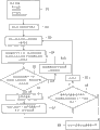
Fig. 1 illustrates the flow chart of expression according to first typical case of the ionizing radiation damage Forecasting Methodology of first embodiment of the invention;
Fig. 2 illustrates a plurality of figure of the typical consequence of diagram through utilizing the performed prediction of plasma gas simulator;
Fig. 3 illustrates a plurality of figure of the typical consequence of diagram through utilizing the performed prediction of sheath layer simulator (sheath simulator);
Fig. 4 illustrates a plurality of figure of the notion in data in graph form storehouse;
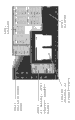
Fig. 5 is the figure that illustrates according to the zoning of the calculating of molecular dynamics;
Fig. 6 A to Fig. 6 C be insert, distribute, generate in defect distribution, based on defect distribution interior through interior slotting calculating damage the Weighted random number and according to through interior insert the damage that obtains distribute to confirm based in the explanation of the degree of depth of random number will reference a plurality of figure;
Fig. 7 illustrates the situation of incident ion to the incident angle
 of projectile energy E with 200eV and 40 degree, in interior slotting explanation will reference a plurality of key diagrams;
Fig. 8 illustrate expression according to first embodiment of the invention, that sheath layer simulator is performed, in order to the flow chart of the processing of the distribution of distribution and the ion incidence angle of prediction ion energy;
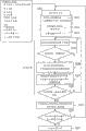
Fig. 9 illustrates the flow chart of second typical case of expression first embodiment of the invention ionizing radiation damage that implement, that be used as the method that is adopted in Si-gate manufacturing Forecasting Methodology;
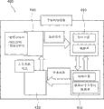
Figure 10 is the figure of general appearance of ionizing radiation damage simulator that the algorithm that pattern provided of embodiment of the present invention is shown;
Figure 11 illustrates the flow chart of the 3rd typical case of expression first embodiment of the invention ionizing radiation damage that implement, that be used as the method that is adopted in Si-gate manufacturing Forecasting Methodology;
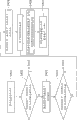
Figure 12 illustrates the flow chart of the algorithm of expression gas simulator;
Figure 13 is the block diagram that illustrates according to first typical case of the ionizing radiation equipment of third embodiment of the invention;
Figure 14 is the figure that is illustrated in according to the general appearance of employed shape simulator in first typical case of the ionizing radiation equipment of the 3rd embodiment;
Figure 15 is the figure of the ionizing radiation method that employed shape simulator adopts in first typical case that is illustrated in according to the ionizing radiation equipment of the 3rd embodiment;
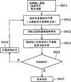
Figure 16 illustrate be illustrated in flow chart shown in Figure 15 step S412 through utilizing simulator so that from database, obtain the flow chart of the details of the calculating that corrected value carries out;
Figure 17 is the block diagram that illustrates according to second typical case of the ionizing radiation equipment of third embodiment of the invention; And
Figure 18 illustrates the flow chart of the ionizing radiation method that expression adopted according to second typical case of the ionizing radiation equipment of the 3rd embodiment.
Embodiment
Hereinafter will be described each preferred embodiment of expression embodiment of the present invention.
< 1. first embodiment >
[first typical case of ionizing radiation damage Forecasting Methodology]
With reference to flow chart shown in Figure 1, first typical case according to the ionizing radiation damage Forecasting Methodology of first embodiment of the invention is described.
Shown in the flow chart of Fig. 1, execution parameter calculation procedure at first.In the calculation of parameter step, through consider to follow the tracks of by incident ion, as calculating the position of collision of the incident ion that enters into manufacturing objective and the incident angle of incident ion to the transmission path in the path of manufacturing objective and through employing DSMC (distribution of the distribution of the projectile energy of its distribution with the flux of incident ion, incident ion, the incident angle of incident ion is as input parameter).
More specifically, according to following execution parameter calculation procedure.At first step S1, confirm input parameter.That is to say, carry out first step S1 in case confirm input parameter (as, the film type of the manufacturing objective of incident ion bombardment, the structure of manufacturing objective, the flux and the length of ionizing radiation time of incident ion).The structure of manufacturing objective comprises the size of manufacturing objective and the shape of manufacturing objective.
Then, at the second step S2, confirm total incident ion counting N.Total incident ion counting N is the sum that in the ionizing radiation time period, is incident to the entering ion of manufacturing objective.According to DSMC, carry out the second step S2 based on input parameter.
Then; At third step S3; Obtain the projectile energy E of incident ion and the incident angle of ion
 more specifically; Carry out third step S3 for the incident angle
(wherein, the appended reference symbol J of suffix as word ' ion ' representes that this ion is a J incident ion) of the projectile energy E of J incident ion J obtaining bombarding manufacturing objective and ion J.
more specifically; Carry out third step S3 for the incident angle
(wherein, the appended reference symbol J of suffix as word ' ion ' representes that this ion is a J incident ion) of the projectile energy E of J incident ion J obtaining bombarding manufacturing objective and ion J.
After having accomplished the above-mentioned parameter calculation procedure, carry out the defect distribution calculation procedure.In the defect distribution calculation procedure, at first, through with reference to the information that obtains in the calculation of parameter step and through the database of creating in advance according to the calculating of first principle of classical molecular dynamics or molecular dynamics in search operaqtion retrieve data.This database comprises: be used to store to manufacturing objective have influence crystal defect amount distribution database, be used for database and the database that is used for the distribution of ion storage penetration depth of the distribution of ion storage reflection probability.Then; Be based on the data that obtain in the search operaqtion, obtain bombarding penetration depth and the penetration site of ion of J incident ion J of incident angle
bombardment manufacturing objective of projectile energy E and ion J of J incident ion J of manufacturing objective.At last, calculate the distribution of the defective that in manufacturing objective, causes by ionizing radiation.
As the distribution of projectile energy E and the distribution of incident angle
 , can utilize the classic predictive result who is produced through plasma gas simulator and sheath layer simulator (it is not shown in the accompanying drawings).As stated; In the operation of searching database and same in, projectile energy E is used as input parameter with incident angle
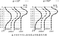
 based on interior slotting calculating.Fig. 2 is a plurality of figure that illustrate through the typical consequence of utilizing the performed prediction of plasma gas simulator.On the other hand, Fig. 3 diagram is used to illustrate a plurality of figure through the typical consequence of utilizing the performed prediction of sheath layer simulator.Replace to utilize to be predicted the outcome, can utilize the value that the result obtained as the actual measurement of the actual measurement of plasma emissioning light or power spectrum through what plasma gas simulator and sheath layer simulator produced.
Aforementioned plasma gas simulator above-mentioned and sheath layer simulator will be described after a while.
More specifically, according to the above-mentioned defect distribution calculation procedure of following execution.
At first; At the 4th step S4; When the incident angle
 of position of collision that calculates incident ion J according to DSMC and ion J, consider the transmission locus of the incident ion J of entering manufacturing objective.More specifically, at the 4th step S4, through adopting DSMC, obtain following the tracks of to the shape of manufacturing objective by incident ion J, as transmission locus to the track of manufacturing objective.For example; Carry out the 4th step S4, so that the transmission path of position of collision between the surface of calculating incident ion J and manufacturing objective and incident ion J combines the surperficial formed incident angle
 of manufacturing objective
In addition; To the incident of each ion with projectile energy E and incident angle
 , calculate the data such as crystal defect D, ion reflection probability P and weighted value F in advance on the manufacturing objective surface.Notice that crystal defect D and weighted value F all are functions of z, wherein, reference symbol z representes the degree of depth of ion penetration.To the manufacturing objective with flat shape, utilization has calculated the data such as crystal defect D, ion reflection probability P and weighted value F according to the simulator of first principle of classical molecular dynamics or molecular dynamics usually.Then, in advance result of calculation is stored as database.That is to say that result of calculation is generally used for creating the database shown in the concept map of Fig. 4.
In the definition that provides as follows (1) or (2), defined calculate through the simulator that utilizes molecular dynamics, as the crystal defect D (z) of a defective that incident ion caused.
(1) according to the definition of the crystal defect D that classical molecular dynamics calculated
Utilization is divided into the unit shown in the sketch map of Fig. 5 according to the zone of the calculating of the simulator of classical molecular dynamics.More properly, usually the zoning is divided into unit 1, unit 2 and the unit 3 that all has big or small 2nm * 2nm * 2nm.As from conspicuous the equality given below (1), the crystal defect D (z) in the unit is defined as the position (X of the atom A that is present in depth z
A, Y
A, Z
A) apart from parent crystal locations of structures (X
AO, Y
AO, Z
AO) each translation sum.The reference symbol N that uses in the equality
AExpression is present in the number of a crystal atoms in the unit.
(2) definition of the crystal defect D that goes out according to the first principle Molecular Dynamics Calculation
According to the first principle molecular dynamics, can calculate the function of the state of molecule or atom as waveform.Defective D (zi) is defined as binding energy in the unit (binding energy) changes delta U sum.Binding energy changes delta U representes by equation DELTA U=U/U0, and is defined defective D (zi) by the phase Calais.Reference character U is represented by the represented covalent bond ability of following equality:
U=∫E×n(E)dE
As from conspicuous the top equality, can U according to state of atom n (E) estimation covalent bond.The reference symbol E that uses in the above-mentioned equality representes Hamilton diagonalization component.On the other hand, reference character U 0 expression of using among the equation DELTA U=U/U0 is to there not being the covalent bond ability under the ion injection situation.
Utilization finally is accumulated in the total damage D among the unit i according to the defined crystal defect D of above-mentioned definition through following equality (2) definition
T(zi):
Employed reference marker Ni representes to be injected into the number of the incident ion of unit i in the equality that provides above (2).
In addition, exist computational methods A and B to be used for confirming the transmission locus of incident ion in the 4th step.Explanation computational methods A and B are following below.
Computational methods A is following such method: it directly advances through repetition in manufacturing objective (like, figure) through the supposition ion and direct reflection (or being penetrated into film) and propagating, and calculates the transmission locus of incident ion.
Computational methods B is following such method: it because the caused electromotive force effect of CHARGE DISTRIBUTION (being also referred to as charge effects) as the CHARGE DISTRIBUTION of patterned surface that the etching manufacturing process is caused, calculates the transmission locus of incident ion through also considering.
According to computational methods (A), with according to ion velocity component (Vx, the gradient Vy/Vx that distribution obtained Vy) and represent transmission locus according to the straight line that radiation position (or relative position) is obtained.
On the other hand; According to computational methods (B); Need to consider the existence of the electronics except ion, calculate Potential Distributing and the Electric Field Distribution created by electronics in the figure and ion, and find the solution ion and the electronic motion equality of propagating through this Potential Distributing and this Electric Field Distribution.Usually, through adopting one by one method (like, successive overelaxation (SOR) method), find the solution this equations of motion with the mode identical with the processing of finding the solution the Poisson equality.For details; Suggestion reader reference documents; Be filed in the thesis for the doctorate of Keio university in 2006 like Taku Shimada, exercise question is " Development Modeling of a Trench Shape ofSiO2 and an Organic Low-Permittivity Material in a SurfaceCharging/Etching/Deposition Competition Process ".
Then, carry out the 5th step S5, penetrate still reflection so that confirm according to the result that reflection probability P and random number ξ are compared that incident ion J has experienced.That is to say; At the 5th step S5; Will be through comparing, so that confirm that it still is the surface reflection of incident ion J by manufacturing objective that incident ion J has penetrated manufacturing objective with reference to the projectile energy E of incident ion J and the incident angle of incident ion J
resulting reflection probability P and random number ξ.
For example, when incident ion J with as the bottom collision of the sidewall of the figure of manufacturing objective or figure the time, the random number ξ that has the value in the scope of being in 0<ξ<1 in this dot generation.In addition, the projectile energy E of retrieval incident ion J and incident angle
 are used it for the spline interpolation processing then to obtain reflection probability P from database.Subsequently; Random number ξ and reflection probability P are compared; So that produce about following such result who confirms: the part that incident ion J has penetrated as the figure of manufacturing objective arrives depth z and causes crystal defect, still incident ion J receives the reflection of patterned surface and the energy of maintenance incident ion J with the direct reflection phenomenon.
If the definite result who produces at the 5th step S5 shows that reflection probability P is littler than random number ξ, that is, concern that ξ>P sets up to indicate incident ion J to penetrate manufacturing objective, carries out following step so.At the 6th step S6, to the data retrieval database such as the type of the film type of manufacturing objective and incident ion J.Database is used for being stored in the distribution of manufacturing objective incident ion.Film type based on the projectile energy E of incident ion J, the incident angle of this ion
 and manufacturing objective; Through according to the calculating of classical molecular dynamics with according to the calculating of first principle of molecular dynamics, created the distribution of incident ion in manufacturing objective in advance.
Then, at the 7th step S7, obtain the penetration depth of incident ion J and the penetration site of incident ion J.More specifically; At the 7th step S7; Be based on resulting data in the search operaqtion that the 6th step S6 carries out, obtain projectile energy E and the penetration depth of incident angle
 incident ion J and the penetration site of this ion J of incident ion J.
Therefore, can obtain having in the unit distribution of the crystal defect that the incident ion J of projectile energy E and incident angle
 caused.Notice that the distribution of crystal defect is the distribution about penetration depth z.In addition, generate Weighted random number and be used for confirming penetration depth z.Note; The Weighted random number is the product of random number and weight F (z); The ion counting distributive law at said weight F (z) expression penetration depth z place, wherein, ion counting distributive law is the ratio of employed total incident ion counting in incident ion counting and the calculating according to molecular dynamics.
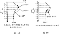
For example, for ξ>P (its expression has generated the situation of crystal defect), come searching database to the film type of manufacturing objective and the type of incident ion J., spline interpolation uses the crystal defect distribution curve shown in Fig. 6 A in handling, so that obtain the crystal defect distribution curve to projectile energy E and the incident angle
 shown in the sketch map of Fig. 6 B.Then, generate the Weighted random number, and use it for and handle resulting crystal defect distribution curve based on spline interpolation shown in the sketch map of Fig. 6 C and confirm penetration depth z.As an example, Fig. 7 illustrates a plurality of key diagrams that spline interpolation is handled to the situation of the incident ion J of the incident angle
 of projectile energy E with 200eV and 40 degree.
Then,, defective data is accumulated, and the ion counting ∑ J of the defective data of being accumulated is compared with total incident ion counting N, concern whether ∑ J>N sets up so that confirm at the 8th step S8.More specifically, accumulate defective data through the penetration depth z of storage incident ion J and the penetration site of ion J.In addition, the ion counting ∑ J of the number of the incident ion J that expression is treated and total incident ion counting N compare, and whether have reached total incident ion counting N so that confirm the number of incident ion J.
If the definite result who produces at the 8th step S8 shows that the number of treated incident ion J does not reach total incident ion counting N as yet; Then flow process advances to the 11 step S11; At the 11 step S11; The represented that kind of equality J=J+1 in the flow chart as shown in Figure 1 increases progressively 1 through index J and upgrades index J.Then, flow process turns back to third step S3, so that (=J+1) indicated incident ion comes reprocessing to the index J after upgrading.
In fact, repeat the sequence of scope, till the number of treated incident ion J reaches total incident ion counting N from the step of third step S3 to the eight step S8.
On the other hand; If the definite result who produces at the 8th step S8 shows that the number of treated incident ion J has reached total incident ion counting N; Then flow process advances to the 9th step S9; At the 9th step S9, ionizing radiation damage Forecasting Methodology stops and creates crystal defect based on the cumulative data of crystal defect distributing.
In addition; On the other hand; If the definite result who produces at the 5th step S5 illustrates reflection probability P and is equal to or greater than random number ξ; Promptly; Concern that ξ≤P sets up the surface reflection by manufacturing objective with indication incident ion J; Then flow process advances to the tenth step S10, at the tenth step S10, incident ion is confirmed as the incident angle
 that has experienced direct reflection and obtained this ion that is to say; At the tenth step S10; Incident ion is confirmed as the direct reflection that has experienced about from manufacturing objective surface reflection ion handle, and the incident angle
of definite this ion then, flow process turns back to the 4th step S4.
that has experienced direct reflection and obtained this ion that is to say; At the tenth step S10; Incident ion is confirmed as the direct reflection that has experienced about from manufacturing objective surface reflection ion handle, and the incident angle
of definite this ion then, flow process turns back to the 4th step S4.
As stated, according to this algorithm, to repeatedly carrying out from the processing of third step S3 to the 11 step S11 by having each J incident ion that the index J that satisfies the value concern 1≤J≤N identified.
Above-mentioned ionizing radiation damage Forecasting Methodology is characterised in that: considered to identify according to DSMC, as the transmission path in the path of following the tracks of by incident ion (or incoming particle) in the manufacturing objective (or figure), use simultaneously through according to the calculating institute of the molecular dynamics database of establishment in advance.Therefore, can reduce significantly to length according to that part of time that calculating distributed of molecular dynamics.In addition, 2 dimensions or 3 dimensions that can also in short time period, calculate the defective that incident ion was caused in the sidewall of the manufacturing objective of creating with 100nm technology (or figure) and/or bottom distribute.Note, be difficult in short time period, calculate 2 dimensions or 3 dimension distributions so far.
For the film that each incident angle and incident ion bombarded of each energy of each type of incident ion, incident ion, incident ion each type provided, comprise usually as the database of the object of search operaqtion: database and the database of weighted value of distribution of database, the database that is used for the distribution of ion storage radiation probability, the ion penetration degree of depth of distribution that is used to be stored in the amount of the crystal defect that generates on the film as the object of ionizing radiation.
According to above-mentioned ionizing radiation damage Forecasting Methodology, can distribute in distribution and 2 dimensions or 3 dimensions of the physical damnification amount (or crystal defect) that incident ion caused of incident ion that the amount decided at the higher level but not officially announced ground prediction of the actual period of computing time is penetrated into sidewall and/or the bottom of manufacturing objective.Note,, be difficult in the actual period of Measuring Time, measure said distribution only through experimentizing.Because use the database of creating in advance through according to the calculating of molecular dynamics, therefore above-mentioned prediction is possible, needs less time to be used to calculate the distribution of the ion penetration degree of depth and the distribution of crystal defect amount thus.
For example, the ionizing radiation damage algorithm that Forecasting Methodology adopted makes and can carry out calculating to the actual graphical with this scale of 100nm.Note,, be difficult to carry out calculating to reality pictures with this scale of 100nm as calculating according to molecular dynamics.Therefore, can obtain the distribution of crystal defect D with beguine according to the higher speed of the speed of the existing calculating of molecular dynamics.Distribution that it should be noted that crystal defect D is meant the information that is shown in the crystal defect D that has generated what degree in the real figure.
In addition, in film, not only can ionizing radiation be damaged Forecasting Methodology and be applied to the crystal defect that incident ion causes as the object of etching manufacturing process, and (like UV (ultraviolet) light) crystal defect that generated that for example can be applied to photon.
In addition; Through utilizing the shape simulator, can predict the distribution of ion dam age to the manufacturing objective (figure) that changes its shape and with true mode to predict this state that has changed the shape of manufacturing objective (figure) owing to the processing such as the etching manufacturing process.Therefore, the two the optimum process condition of defective that shape standard and ion dam age caused that adopted can be provided.Notice that the defective that ion dam age caused is considered to the relevant defective of electrical characteristics with the device of making.
After a while the shape simulator will be described.
[typical sheath layer simulator]
According to DSMC, sheath layer simulator is used for prediction processing.In the performed prediction processing of sheath layer simulator; The ionizing radiation that will have the speed that distributes based on maxwell is to the sheath layer region; In this sheath layer region, each ion is owing to the electrical potential difference between ion and the sheath layer region is quickened, and with the sheath layer region in the neutral particle collision that exists.Each ion repeats said acceleration and collision.
Fig. 8 illustrates the flow chart of the performed processing of expression sheath layer simulator.
As shown in Figure 8, this flow chart begins as the input parameter that input parameter is set processed steps S20 to be set.Input parameter comprises electron density or plasma density, electron temperature, ion temperature, mass of ion, neutral particle temperature, neutral particle quality, air pressure, below-center offset frequency, self-induction biasing Vdc, descends the outer number that is biased Vrf and incident ion.
After input parameter is provided with step, through carrying out: be provided with initial rate step S21, be provided with biasing the initial phase part step S22 and be provided with apart from the step S23 of the distance of collision, carry out the particle injection technology.
More specifically, at first,, the initial rate of ion is set based on the random number that is generated at step S21.For example, provide the initial rate of ion according to maxwell's distribution.
Then, at step S22, the initial phase part of biasing is set based on the random number that is generated.Subsequently, at step S23, the distance of distance about the collision of manufacturing objective is set based on the random number that is generated.
Then, carry out the step S24 of conduct biasing accelerating step.That is to say,, ion is quickened through biasing being applied to ion in the biasing accelerating step.
Subsequently, execution is as the step S25 of flying distance and collision distance comparison step.At step S25, shorter about the distance of the collision of manufacturing objective than distance if ' flying distance<collision distance ' set up with the indication flying distance, then flow process turns back to step S24, in this step 24, through biasing being applied to ion ion is quickened.
On the other hand; If relation ' flying distance >=collision distance ' is set up to indicate flying distance to equal or to be longer than the distance of distance about the collision of manufacturing objective; Then flow process advances to step S26; At this step S26, the collision rear of calculating ion based on the random number that is generated to and the collision of ion after energy.For example, execution in step S26 is so that calculate based on the random number that is generated: the collision back reflection direction of the reflection direction of the collision between ion and the manufacturing objective is followed in the conduct that obtains as penetration direction or incident ion after the collision of penetration direction after the collision between ion and the manufacturing objective that incident ion is obtained.In addition, also calculate energy after the collision of ion based on the random number that generates.
Then, execution in step S27 is so that make the ion acceleration and obtain the distance that distance is collided based on the random number that generates through biasing being applied to ion.That is to say, through the biasing that is applied to ion incident ion is quickened, and come the distance of the collision between computed range and the manufacturing objective surface based on the random number that generates.
Subsequently, execution is as the step S28 of flying distance and sheath layer region thickness comparison step.At step S28, shorter than the thickness of sheath layer region if ' thickness of flying distance<sheath layer region ' is set up with the indication flying distance, then flow process turns back to step S24, at this step S24, through biasing being applied to ion ion is quickened.
On the other hand; If relation ' thickness of flying distance >=sheath layer region ' is set up the thickness that equals or be longer than the sheath layer region with the indication flying distance; Then flow process advances to step S29, at this step S29, calculates incidence angle and the projectile energy of basis time of incidence of basis (basic) time of incidence.For example, before getting into the sheath layer region, ion has the speed that distributes according to aforesaid Mace Wei Er.Then, the ion entering sheath layer region that has the speed that distributes according to Mace Wei Er.When ion got into the sheath layer region, because the electrical potential difference between ion and the sheath layer region, the sheath layer region quickened ion.When ion just quickened, ion also collided with neutral particle.Usually through adopting DSMC to calculate the repetition of acceleration and the repetition of collision.
Then, execution is as the step S30 that produces about the following result's who confirms step, and said confirming as: whether the number of treated particle is less than the particle counting that is provided with of representing number of particles.If the definite indexical relation as a result that produces at step S30 ' number of treated particle<be provided with particle counting ' (its number that means treated particle is less than particle counting is set) is set up, then flow process turns back to the particle injection technology that begins with step S21.
On the other hand, set up if confirm as a result indexical relation ' number of treated particle >=be provided with particle counting ', then the flow process of prediction processing advances to and stops calculated/predicted processed steps S31.
Sheath layer simulator carried out the calculating based on above-mentioned algorithm, so that the behavior of incident ion in the prediction sheath layer region.
[second typical case of ionizing radiation damage Forecasting Methodology]
Following description has been explained according to first typical case of damaging Forecasting Methodology based on the ionizing radiation of first embodiment of the invention, is used for the performed processing of etching manufacturing process prediction damage distribution at Si-gate.The technology that is adopted in this prediction processing is called second typical case according to the ionizing radiation damage Forecasting Methodology of first embodiment of the invention.Fig. 9 shows second typical case according to ionizing radiation damage Forecasting Methodology, and expression is used for the flow chart at the typical calculation algorithm of the etching manufacturing process prediction damage distribution of Si-gate.
Flow chart shown in Figure 9 begins with the first step S101 that confirms input parameter.More properly, carry out this first step S101 and confirm input parameter, as, as through with the length of ionizing radiation to graphic structure, ionic flux and the etch period of the type of the film of the object of the performed etching manufacturing process of film, film.Graphic structure as the film of the object of etching manufacturing process comprises the feature size of film and the graphics shape of film.
Then, at the second step S102, confirm total incident ion counting N.More specifically; The sum of the incident ion of the film that total incident ion counting N is the object that bombardment is used as the etching manufacturing process in the ionizing radiation time period; And,, confirm total incident ion counting N based on input parameter according to DSMC at the second step S102.
Then, at third step S3, confirm the input parameter of sheath layer simulator.The input parameter of sheath layer simulator is at the set input parameter of the step S20 of flow chart shown in Figure 8.As discussed previously, the input parameter that is provided with at the step S20 of flow chart shown in Figure 8 comprises electron density or plasma density, electron temperature, ion temperature, mass of ion, neutral particle temperature, neutral particle quality, air pressure, below-center offset frequency, self-induction biasing Vdc, is biased Vrf and total incident ion is counted outward down.
Then, at the 4th step S104, carry out calculating through utilizing sheath layer simulator.In using the performed calculating of sheath layer simulator, simulator carries out emulation to the incident of incident ion J with primary power and incident angle.That is to say that simulator carries out emulation to the behavior of incident ion J in the sheath layer region.For example, obtain entering to projectile energy and incident angle as the incident ion J of the film of the object of etching manufacturing process, wherein, this ion of reference symbol J indication is a J incident ion.
Then, carry out the 5th step S105 as through the transmission path considering to follow the tracks of and through adopting DSMC, calculate step in order to the incident angle of the position of collision of the incident ion J of bombardment manufacturing objective and incident ion J by incident ion J.At the 5th step S105, through adopting DSMC, obtain following the tracks of to the shape of manufacturing objective by incident ion J, as transmission locus to the track of manufacturing objective.For example, carry out the 5th step S105, so that the position of the collision between the surface of calculating incident ion J and manufacturing objective, and the transmission path of incident ion J combines the surperficial formed incident angle of manufacturing objective.
In addition; To the incident of each ion that has projectile energy E and incident angle
 on the manufacturing objective surface, calculate the data such as crystal defect D, ion reflection probability P and weighted value F in advance.Notice that crystal defect D and weighted value F are the function of z, wherein, reference symbol z representes the degree of depth of ion penetration.Usually to the manufacturing objective with flat shape, utilization has calculated above-mentioned data according to the simulator of first principle of classical molecular dynamics or molecular dynamics.Then, in advance result of calculation is stored as database.That is to say that result of calculation is generally used for creating the database shown in the concept map of Fig. 4.
Then, carry out the 6th step S106, penetrate still reflection to confirm that according to the result that reflection probability P and random number ξ are compared incident ion J has experienced.That is to say; At the 6th step S106; Will be through comparing with reference to the projectile energy E of incident ion J and incident angle
 resulting reflection probability P and random number ξ; So that confirm that based on comparative result incident ion J has penetrated manufacturing objective, or incident ion J is by the surface reflection of manufacturing objective.
For example, when incident ion J with as the bottom collision of the sidewall of the figure of manufacturing objective or figure the time, the random number ξ that has the value in the scope of being in 0<ξ<1 in this dot generation.In addition, from database the projectile energy E of retrieval incident ion J with incident angle
 and use it for the spline interpolation processing to obtain reflection probability P.Subsequently; Random number ξ and reflection probability P are compared; So that produce the result who confirms about following: the part figure that incident ion J penetrates as manufacturing objective arrives depth z and causes crystal defect, still incident ion J with the direct reflection phenomenon by the energy of the surface reflection of figure and maintenance incident ion J.
If the definite result who produces at the 6th step S106 shows that reflection probability P is littler than random number ξ, that is, concern that ξ>P establishment and indication incident ion J have penetrated manufacturing objective, carry out following step so.At the 7th step S107, to the data such as the type of the film type of manufacturing objective and incident ion J and searching database.Database is used for being stored in the distribution of manufacturing objective incident ion.Based on the film type of the projectile energy E of incident ion J, the incident angle of this ion
 and manufacturing objective, through according to the calculating of classical molecular dynamics and according to the calculating of first principle of molecular dynamics and created the distribution of incident ion in manufacturing objective in advance.
For example, for ξ>P (its expression has generated the situation of crystal defect), come searching database to the film type of manufacturing objective and the type of incident ion J., spline interpolation uses the crystal defect distribution curve shown in Fig. 6 A in handling, so that obtain the crystal defect distribution curve to projectile energy E and the incident angle
 shown in the sketch map of Fig. 6 B.As an example, Fig. 7 illustrates a plurality of key diagrams that spline interpolation is handled to the situation of the incident ion J of the incident angle
 of projectile energy E with 200eV and 40 degree.
Then, at the 8th step S108, obtain the penetration depth of incident ion J and the penetration site of ion J.More specifically; At the 8th step S108; Be based on the data that obtain in the search operaqtion of the 7th step S107 execution, obtain projectile energy E and incident angle
 penetration depth of incident ion J and the penetration site of ion J of incident ion J.
Therefore, can obtain having in the unit distribution of the crystal defect that the incident ion J of projectile energy E and incident angle
 caused.Notice that the distribution of crystal defect is the distribution about penetration depth z.In addition, generate Weighted random number and use it for and confirm penetration depth z.Note; The Weighted random number is the product of random number and weight F (z); The ion counting distributive law at said weight F (z) expression penetration depth z place, wherein, ion counting distributive law is the ratio of employed total incident ion counting in incident ion counting and the calculating according to molecular dynamics.
Then,, defective data is accumulated, and the ion counting ∑ J of the defective data of being accumulated is compared with total incident ion counting N, concern whether ∑ J>N sets up so that confirm at the 9th step S109.More specifically, accumulate defective data through the penetration depth z of storage incident ion J and the penetration site of ion J.In addition, the ion counting ∑ J of the number of the incident ion J that expression is treated and total incident ion counting N compare, and whether have reached total incident ion counting N so that confirm the number of treated incident ion J.
If the definite result who produces at the 9th step S109 shows that the number of treated incident ion J does not reach total incident ion counting N as yet; Then flow process advances to the 12 step S112; At the 12 step S112; The represented that kind of equality J=J+1 in the flow chart as shown in Figure 9 is upgraded index J through increasing progressively 1 to the index J of incident ion.Then, flow process turns back to the 4th step S104, so that (=J+1) indicated incident ion comes reprocessing to the index J after upgrading.
In fact, repeat the sequence of scope, till the number of treated incident ion J reaches total incident ion counting N from the step of the 4th step S104 to the nine step S109.
On the other hand; If the definite result who produces at the 9th step S109 shows that the number of treated incident ion J has reached total incident ion counting N; Then flow process advances to the tenth step S110; At the tenth step S110, ionizing radiation damage Forecasting Methodology stops and creates crystal defect based on the crystal defect data of being accumulated distributing.
In addition; On the other hand; If the definite result who produces at the 6th step S106 shows that reflection probability P is equal to or greater than random number ξ; Promptly; Concern that ξ≤P establishment and indication incident ion J are by the surface reflection of manufacturing objective; Then flow process advances to the 11 step S111, at the 11 step S111, incident ion is confirmed as the incident angle
 that has experienced direct reflection and obtained this ion that is to say; At the 11 step S111; Incident ion is confirmed as the direct reflection that has experienced from the surface reflection ion of manufacturing objective handle, and the incident angle
 that detects this ion then, flow process turns back to the 5th step S105 to repeat to start from the processing of this step.
As stated, according to this algorithm, to by having each J incident ion that the index J that satisfies value concern 1≤J≤N is identified, execution repeatedly starts from the 4th step S104 and ends at the processing of the 12 step S112.
According to above-mentioned algorithm, thus can be in the distribution of the over etching that utilizes the resist figure as the Si-gate manufacturing process of mask (over etching) step prediction each damage that hydrogen ion caused.At the employed resist figure of over etching step is grid manufacturing assessment figure.The structure of resist figure has the resist film thickness of 250nm, the BARC of 80nm (Bottom Anti Reflective Coating, bottom antireflective coating) film thickness, the silicon thin film thickness of 150nm, the spacing of 300nm and the live width of 100nm.In addition, cell size being set is 2nm * 2nm * 2nm.The resist figure is the figure with solid shape, and it does not change in the process of prediction.Be provided for having the database in the zone of the size that equates with cell size in advance.Database is created in calculating through according to molecular dynamics.The typical case of this database has been shown in the sketch map of below among Fig. 4.To 10
16/ scm
2Ionic flux and 10 seconds etch period section carry out the over etching step.Total incident ion counting N that bombardment has the resist figure of big or small 500nm * 2nm is 1 * 10
16This incident ion sum is corresponding to this over etching step.In addition; Through under following condition, described sheath layer simulator before utilizing and obtain the distribution of ion energy E and the distribution of incident angle
 .This distributes as based on the input parameter in the calculating said algorithm (through with reference to flow chart shown in Figure 9 and in before it being carried out explanation), that calculate as the transmission path in the resist figure, and as based on the input parameter in the interior slotting calculating of database.Note, utilize the resulting input parameter of calculating of sheath layer simulator to be used as in the determined parameter of the third step S103 of flow chart shown in Figure 9.
Sheath layer simulator is set to work under following representative condition:
Electron energy: 5eV
Ion temperature: 1,000K
Neutral particle temperature: 400K
Air pressure: 1.33Pa, 13.3Pa and 6.7Pa
Plasma density: 10
10/ cm
3
Plasma potential: 20V
Applying bias voltage: 200V
Self-bias voltage :-200V
Add offset frequency: 13.56MHz
Mass of ion: 1amu
Neutral particle quality: 1amu
Use the platform of Windows/Cygwin OS as the execution of the code that is used for this algorithm.Yet, equally also can use another OS to come as this platform.The typical case of other OS is the OS of Mac, OSX, LINUX and UNIX series.Algorithm itself is write (even equally also can use any other language) through utilizing Fortran 77.The typical case of said other language is Fortran90, Fortran95, C, C++ and JAVA.That is to say that the language that is used to write algorithm is not a problem.
Figure 10 is the figure that the general appearance of the ionizing radiation damage simulator of implementing said algorithm is shown.The interface portion of simulator is made up of tcl/tk and PGPLOT.The interface portion of simulator makes that calculation control is visible with calculating for the user.Yet, also can use another control system language and another instrument.
Then, calculate 2 dimension distributions of the defective that ion caused of each air pressure radiation in air pressure 1.33Pa, 13.3Pa and 6.7Pa.In addition, equally also obtain being directed against the ion energy distribution of the same terms.In addition, predict that equally also Ion paths combines the distribution of formed each incident angle of patterned surface.Through utilize Windows/Cygwin OS as computer (its have as the CPU of computer, frequency is the Intel Pentium M processor of 1.60GHz) in the platform of execution, can be with being reduced to computing time 50 hours.On the other hand, if only carry out calculating, then to having 2nm * 2nm size and among it, not creating sample in the plane domain of figure and carry out that to calculate the time that is spent be 2000 hours according to molecular dynamics.It is obvious that thus, comes can reduce computing time significantly with the method that acts on the prediction damage that ionizing radiation caused through adopting method provided by the invention.Notice that be the situation of the value that is set to equate with value for simulator computing time of 50 hours to dosage 2000 hours computing time, execution is according to the time that calculating spent of molecular dynamics.
In addition, according to ionizing radiation damage Forecasting Methodology of the present invention, the film that is used as the object of manufacturing process (like etching manufacturing process or ion implantation technology) needs not be the film of being made by silicon.For example, this film also can be the film made by silicon dioxide, the film made by silicon nitride, organic film or by another film of made.
In addition, in the method for the invention, the shape of having used the figure of this method is not a problem.That is to say that the structure of figure is not necessarily the structure of grid.For example, the structure of figure can be side wall construction, shallow ridges structure, damascene structure, contact hole structure or through hole (via-hole) structure.In addition, through describe fixedly figure (as, be used as the figure of the object of over etching manufacturing process) and example the method for the damage that is used to predict that ionizing radiation causes.Yet, the graphics shape that also can this method is applied to change along with the process of time.The typical case of the time dependent figure of shape is the figure as the object of main etching manufacturing process.In addition, even the application that is used to predict the method that 2 dimension damages distribute has been described, but the present invention equally also can easily extend to and is used to the method for predicting that 3 dimension damages distribute.
In addition, in order to improve the precision of calculating, can consider charge effects.Charge effects be in the process of etching manufacturing process, be accumulated in charge generation on the patterned surface electrical potential difference caused, as influence for the influence of the transmission locus of ion and electronics.Therefore, through considering charge effects, can influence the transmission locus of discerning incident ion through the electrical potential difference that radiation produced of considering incident ion and incident electron for manufacturing objective.
Above-mentioned ionizing radiation is the ionizing radiation of in plasma etch process, carrying out.Therefore, be added into the database of creating according to the calculating of molecular dynamics through the conductivity with manufacturing objective, can be directed against the sidewall and/or the bottom of the manufacturing objective of the object that is used as plasma etch process, 2 dimensions or 3 dimensions of calculating conductivity distribute.
[the 3rd typical case of ionizing radiation damage Forecasting Methodology]
The following description according to first typical case of damaging Forecasting Methodology based on the ionizing radiation of first embodiment of the invention explains that the etching manufacturing process prediction that is used at Si-gate damages other the performed processing that distribute.These other technology that adopted in handling is called the 3rd typical case according to the ionizing radiation damage Forecasting Methodology of first embodiment of the invention.Figure 11 shows the 3rd typical case according to ionizing radiation damage Forecasting Methodology, and expression is used for the flow chart at the typical calculation algorithm of the etching manufacturing process prediction damage distribution of Si-gate.Through with reference to flow chart shown in Figure 11, damage the 3rd typical case of Forecasting Methodology according to following such explanation ionizing radiation.
Flow chart shown in Figure 11 begins with the first step S101 that confirms input parameter.More properly; Carry out this first step S101 and confirm input parameter; As, as the type of the film of the object through etching manufacturing process that ionizing radiation is carried out to film, be used as the length of graphic structure, ionic flux and etch period of film of the object of etching manufacturing process.Graphic structure as the film of the object of etching manufacturing process comprises the feature size of film and the graphics shape of film.
In the case, obtain ionic flux as the result calculated of carrying out at step S122 (it is for carrying out the step that the gas simulator calculates).As input parameter, come the calculating of execution in step S122 through the formulation parameter that will generate at formulation parameter step S121.Formulation parameter is the parameter of true process conditions.
Then, at the second step S102, confirm total incident ion counting N.The sum of the incident ion of the film that total incident ion counting N is the object that bombardment is used as the etching manufacturing process in the ionizing radiation time period.The second step S102 is according to DSMC, carries out based on input parameter.
Then, at third step S103, confirm the input parameter of sheath layer simulator.The input parameter of the sheath layer simulator of third step S103 is at the set input parameter of the step S20 of flow chart shown in Figure 8.As discussed previously, this input parameter comprises electron density or plasma density, electron temperature, ion temperature, mass of ion, neutral particle temperature, neutral particle quality, air pressure, below-center offset frequency, self-induction biasing Vdc, descends the outer number that is biased Vrf and incident ion.
Then, at the 4th step S104, carry out calculating through utilizing sheath layer simulator.In utilizing the performed calculating of sheath layer simulator, simulator carries out emulation to the incident of the incident ion J of primary power with incident and angle.That is to say that simulator carries out emulation to the behavior of incident ion J in the sheath layer region.For example, obtain projectile energy and the incident angle of incident ion J, wherein, the reference symbol J that attaches to word ' ion ' as suffix shows that this ion is a J incident ion.
Then, carry out the 5th step S105 as adopting DSMC, through the transmission path of considering that incident ion J follows the tracks of, the step of the position of collision of the incident ion J of calculating bombardment manufacturing objective and the incident angle of incident ion J.That is to say, when obtaining position of collision and incident ion J between incident ion J and the manufacturing objective surface and combine the surperficial formed incident angle of manufacturing objective, transmission locus is taken into account.Particularly, at the 5th step S105, through adopting DSMC, to the shape of manufacturing objective obtain that incident ion J follows the tracks of, as transmission locus to the track of manufacturing objective.
In addition; To the incident of each ion that has projectile energy E and incident angle
 on the manufacturing objective surface, calculate the data such as crystal defect D, ion reflection probability P and weighted value F in advance.Notice that crystal defect D and weighted value F are the function of z, wherein, reference symbol z representes the degree of depth of ion penetration.Usually to the manufacturing objective with flat shape, utilization has calculated the data such as crystal defect D, ion reflection probability P and weighted value F according to the simulator of first principle of classical molecular dynamics or molecular dynamics.Then, in advance result of calculation is stored as database.That is to say that result of calculation is generally used for creating the database shown in the concept map of Fig. 4.
Then, carry out the 6th step S106, penetrate still reflection to confirm that according to the result that reflection probability P and random number ξ are compared incident ion J has experienced.That is to say; At the 6th step S106; Will be through comparing with reference to the projectile energy E of incident ion J and incident angle
resulting reflection probability P and random number ξ; So that confirm that based on comparative result incident ion J has penetrated manufacturing objective, or incident ion J is by the surface reflection of manufacturing objective.
For example, when incident ion J with as the bottom collision of the sidewall of the figure of manufacturing objective or figure the time, the random number ξ that has the value in the scope of being in 0<ξ<1 in this dot generation.In addition, from database the projectile energy E of retrieval incident ion J with incident angle
and use it for the spline interpolation processing to obtain reflection probability P.Subsequently; Random number ξ and reflection probability P are compared; So that produce the result who confirms about following: the part figure that incident ion J penetrates as manufacturing objective reaches depth z and causes crystal defect, still incident ion J with the direct reflection phenomenon by the energy of the surface reflection of figure and maintenance incident ion J.
If showing, the definite result who produces at the 6th step S106 concern that ξ>P sets up and indicates incident ion J to penetrate manufacturing objective, carries out the following step so.At first, at the 7th step S107, to the data such as the type of the film type of manufacturing objective and incident ion J and searching database.This database is the database that is used for being stored in the distribution of manufacturing objective incident ion.Based on the projectile energy E of incident ion J and the film type of incident angle
 and manufacturing objective, through according to the calculating of classical molecular dynamics and according to the calculating of first principle of molecular dynamics and created the distribution of incident ion in manufacturing objective in advance.
For example, for ξ>P (its expression has generated the situation of lattice defect), come searching database to the film type of manufacturing objective and the type of incident ion J., spline interpolation uses the crystal defect distribution curve shown in Fig. 6 A in handling, so that obtain the crystal defect distribution curve to projectile energy E and the incident angle shown in the sketch map of Fig. 6 B.As an example, Fig. 7 illustrates a plurality of key diagrams that spline interpolation is handled to the situation of the incident ion J of the incident angle
 of projectile energy E with 200eV and 40 degree.
Then, at the 8th step S108, obtain the penetration depth of incident ion J and the penetration site of ion J.More specifically; At the 8th step S108; Be based on the data that obtain in the search operaqtion of the 7th step S107 execution, obtain projectile energy E and incident angle
 penetration depth of incident ion J and the penetration site of ion J of incident ion J.
Therefore, can obtain having in the unit distribution of the crystal defect that the incident ion J of projectile energy E and incident angle
 caused.Notice that the distribution of crystal defect is the distribution about penetration depth z.In addition, generate Weighted random number and use it for and confirm penetration depth z.Note; The Weighted random number is the product of random number and weight F (z); The ion counting distributive law at said weight F (z) expression penetration depth z place, wherein, ion counting distributive law is the ratio of employed total incident ion counting in incident ion counting and the calculating according to molecular dynamics.
Then,, defective data is accumulated, and the ion counting ∑ J and the incident ion counting N of the defective data of being accumulated compared, concern whether ∑ J>N sets up so that confirm at the 9th step S109.More specifically, accumulate defective data through the penetration depth z of storage incident ion J and the penetration site of ion J.In addition, the ion counting ∑ J of the number of the incident ion J that expression is treated and total incident ion counting N compare, so that produce the result who confirms who whether has reached total incident ion counting N about the number of incident ion J.
If the definite result who produces at the 9th step S109 shows that the number of treated incident ion J does not reach total incident ion counting N as yet; Then flow process advances to the 12 step S112; At the 12 step S112; The represented that kind of equality J=J+1 in the flow chart shown in figure 11 is upgraded index J through increasing progressively 1 to the index J of incident ion.Then, the flow process of the process of ionizing radiation damage Forecasting Methodology turns back to the 4th step S104, so that (=J+1) indicated incident ion comes reprocessing to the index J after upgrading.
In fact, repeat the sequence of scope, till the number of treated incident ion J reaches total incident ion counting N from the step of the 4th step S104 to the nine step S109.
On the other hand; If the definite result who produces at the 9th step S109 shows that the number of treated incident ion J has reached total incident ion counting N; Then flow process advances to the tenth step S110; At the tenth step S110, ionizing radiation damage Forecasting Methodology stops and creates crystal defect based on the crystal defect data of being accumulated distributing.
In addition; On the other hand; If showing, the definite result who produces at the 6th step S106 concern that ξ≤P sets up and indicates incident ion J by the surface reflection of manufacturing objective; Then flow process advances to the 11 step S111; At the 11 step S111; Incident ion is confirmed as the incident angle
 that has experienced direct reflection and obtained this ion that is to say; At the 11 step S111; Incident ion is confirmed as the direct reflection that has experienced from the surface reflection ion of manufacturing objective handle, and the incident angle
 that detects this ion then, flow process turns back to the 5th step S105 so that repeat to start from the processing of this step.
As stated, according to this algorithm, repeatedly carry out the processing that starts from the 4th step S104 and end at the 12 step S112 to having each J the incident ion that index J identified that satisfies the value that concerns 1≤J≤N.
The 3rd typical case of the method for the damage that is used to predict that incident ion causes be indifferent to equally as the type of the film of the object of etching manufacturing process, as the type of the structure of the figure of the object of etching manufacturing process and figure along with the process of time is fixedly or variation.In addition, can charge effects be taken into account equally.
Through the algorithm that is adopted with reference to flowchart text gas simulator shown in Figure 12.
Shown in figure 12, this flow chart is to be used for confirming that the step S201 of parameter begins.Parameter generally includes technique information, facility information, wafer information and the conduct wall state information about the information of chamber wall.Technique information comprises electron temperature, pressure (that is, handling allowable temperature), flow (that is, handling the flow of gas), ion temperature, neutral particle temperature, body (bulk) plasma density and etch period section.Facility information comprises radius, gap length (that is, being used as the wafer of manufacturing objective and the distance between the top electrode), the radius of top electrode and the volume of chamber of chamber.Wafer information comprises the radius of aperture ratio and wafer.The wall state information comprises the bonding probability of particle, like particle for the bonding probability of top board and particle bonding probability for sidewall.
Then, execution in step S202 calculates electron density.For example, in the calculating of electron density, use the value that from positive aura post (glow pillar) model, obtains.Alternatively, provide actual measured value.
Calculating according to following such explanation electron density.
About distribution as the electron density (like plasma density) of the input parameter of model, suppose in the fluid continuity equality, to exist stable state and have axial symmetry distribution n (r), obtain the represented diffusion equation of equality (3) according to positive aura post theory.In equality (3), reference marker v representes collision frequency, and reference marker D representes diffusion coefficient.
Equality (3) is called the Bezier difference equation.Suppose density n to r=0
0, shown in equality 4, can be with J
0Expression is separated for the Bezier equality.In equality (4), reference marker J
0Represent the 0th rank Bessel function.
As in the cylindrical side wall of chamber wall, suppose n=0 for r=R, the minimal solution that satisfies J=0 is 2.405.That is to say, such shown in equality (5), represent electron density distribution n (r) with radius R wo apart from r and chamber apart from the chamber center.
Therefore, can obtain the electron density of each position in the chamber.
Then, at step S203, calculate particle density and flux.Through Cl (chlorine) family gas has been carried out example to the calculating of ion concentration and flux as an example.Certainly, the following description of particle density and flux is set up for the gas except Cl (chlorine) family gas equally.For example, for being directed against each ion radical density (radical density), represent about Cl, Cl by equality (6) along with change of time
+, Cl
++, Cl
-, Cl
2 +, SiCl
4And SiCl
2The simultaneous ordinary differential equation group:
Wherein,

∑
mK
mN (i, t) n (j, t) expression m type chemical reaction,


In the equality that provides in the above (6), reference symbol n (i, the t) density of expression particle of interest, reference symbol k
m(j, t) expression is as the chemical reaction companion's of particle of interest Particle Density, reference symbol τ for expression chemical reaction rate, reference symbol n
rThe expression emission characteristics time, reference symbol τ
nThe expression diffusion property time.The represented simultaneous ordinary differential equation group of the equality that provides above (6) is handled the each item with very different each other rank.Said be exemplified as: electron density, chemical reaction rate and time step.Therefore, through only adopting 4 common rank Rung-Kutta methods, separating of simultaneous ordinary differential equation group possibly not restrain in some cases.In order to address this problem, this model adopts as the recessive method of value solving of being prepared to rigidity ordinary differential Simultaneous Equations and known Gear method.In addition, with electron density and Cl
2Density all is assumed to be constant.This is because than other chemical reactions, the markers of the main chemical reaction of plasma conversion (time scale) (relaxation markers (relaxation time scale)) less (less than 0.1nsec), and always provide gas.
As stated, the reference symbol τ in the expressed simultaneous ordinary differential equation group of equality (6)
rIndication is with the represented emission characteristics time of second.Represent emission characteristics time τ through equality given below (7)
rRight-hand side in equality (7), reference symbol P are indicated with the represented air pressure of mT, and reference symbol V indication is rising represented chamber volume, and total flow of liquid that reference symbol Q indication is represented with sccm.Emission characteristics time τ
rHave the value of scope between 1msec and tens msec.
In addition, equally as stated, the reference symbol τ in the represented simultaneous ordinary differential equation group of equality (6)
nIndication is with the represented diffusion property time of second.Represent τ diffusion time through equality given below (8)~(13)
nIn equality (8)~(13), reference symbol Λ indication characteristic diffusion length, and reference character D indication diffusion constant.Can be under the situation of hypothesis plasma body portion (plasma bulk portion), through come approximate characteristic diffusion length Λ about the diffusion length of cylindrical plasma for the object of consideration.On the other hand, diffusion constant D is two electrode diffusion constants.In addition, in equality (8)~(13), reference symbol R indicates with the represented chamber radius of cm, and reference symbol v indication is used to represent the Collision Number purpose collision frequency of per second, reference symbol k
BIt is (1.308 * 10 that indication has value
-23J/K) Boltzmann constant, reference symbol T
eIndication is so that (electron temperature that eV * 11600K) is represented, reference symbol m indicates with (Z * 1.627 * 10
-27Kg) represented mass of ion, reference symbol n
0Indication is with m
-3Represented plasma density, reference symbol λ
DIndication is with the represented Debye length of debye (Debye) unit.Diffusion property time τ
nValue with millisecond magnitude.
v=2.9×10
-12n
0×logY/T
e 1.5 ...(11)
Then,, suppose Baum speed and warm-up movement speed, can represent the flux Γ of ion respectively through equality given below (14) and (15) through utilizing as the particle density that is obtained of separating for the simultaneous ordinary differential equation group
IonWith basic flux Γ
BaseIn equality (14) and (15), reference symbol k
BThe expression Boltzmann constant, reference symbol T
eThe expression electron temperature, reference symbol T
nExpression Ji Wendu, reference symbol n
iThe expression ion concentration, reference symbol n
nThe expression base density, reference symbol M
iThe quality of expression ion, reference symbol M representes the matrix amount.


As stated, can calculate particle density and flux.
Then, execution in step S204 is so that determine whether to have passed through section computing time.That is to say that execution in step S204 is so that produce about whether having passed through the result who confirms of set etch period section.After set etch period section, accomplish if the result who confirms shows based on the computing of algorithm, the flow process of handling so advances to the step S205 that stops computing.On the other hand; If the result who confirms show the computing based on algorithm be not set etch period section after completion (promptly; If the result who confirms shows based on the computing of algorithm in set etch period section, accomplish), the flow process of then handling advances to the expansion of time of implementation so that the step S206 that computing is expanded.At step S206,, calculate particle density and flux once more through after the predetermined time.Then, the flow process of computing turns back to step S204 so that such as stated generation about whether having passed through the result who confirms of set etch period section.In fact, step S204 and S206 repeat, till having passed through set etch period, that is, and up to said confirm to show after set etch period section, accomplished based on the computing of algorithm till.When the result who confirms shows that when set etch period section after, having accomplished based on the computing of algorithm, the flow process of processing advances to the step S205 of termination computing.
When in execution, utilizing the database of creating according to the calculating of first principle of molecular dynamics, such shown in the sketch map of below in can image pattern 4 conductivity be added into database according to first to the 3rd typical case of the ionizing radiation Forecasting Methodology of first embodiment of the invention.Through by this way conductivity being added into database, can be in the process of manufacturing process and the prediction manufacturing process is damaged after manufacturing process just zone in the distribution of conductivity.That is to say, during manufacturing process and afterwards, can predictive of impaired hinder the electrical property change in the zone.Insert in being used for from the method for the value of this database with pass through before identical with reference to the illustrated method of the figure of figure 6.
According to Hamiltonian, the method through adopting the wave function that is calculated based on first principle according to molecular dynamics and based on the method for nonequilibrium state Green's function is calculated the conductivity that in the processing of creating database, is added into database.For with the relevant more information of method that is used to calculate conductivity, suggestion reader reference documents, as Meir and Wingreen in 1992 at Phys.Rev.Lett., Vol.68, the article of being shown in p.2512.
< 2. second embodiment >
[typical ionizing radiation damage simulator]
According to the typical case of following such explanation according to the ionizing radiation damage simulator of second embodiment of the invention.
The typical case of ionizing radiation damage simulator comprises:
The processing section, it is configured to: carry out and calculate the defective that generates in said manufacturing objective owing to be radiated the incident ion of manufacturing objective with prediction; And
Output, it is configured to: said handling part branch is calculated, export as the defect distribution of the defect distribution that in said manufacturing objective, generates owing to being radiated the incident ion of said manufacturing objective.
The processing section through adopt all in before illustrated, as according in the computational algorithm of the algorithm of one of first to the 3rd exemplary embodiments of the ionizing radiation damage Forecasting Methodology of first embodiment of the invention any one, carry out calculating to predict defective.
On the other hand, the normally following such image display of output: this image display is used for showing the defect distribution of the defect distribution that the handling part branch calculates, that conduct generates at said manufacturing objective owing to the incident ion that is radiated said manufacturing objective.Alternatively, output is following such PRN device: this PRN device is used for the defect distribution of print processing part defect distribution that calculated, that conduct generates at said manufacturing objective owing to the incident ion that is radiated said manufacturing objective.Substitute as another, the normally following such memory device of output: this memory device is used for the defect distribution of the defect distribution that storing process part calculates, that conduct generates at said manufacturing objective owing to the incident ion that is radiated said manufacturing objective.The typical case of memory device is a hard disk.Through defect distribution being stored in the memory device such as hard disk, can using defect distribution and process conditions are fed back to the control section that ionizing radiation equipment (it is to be used for the equipment of ionizing radiation to manufacturing objective) is adopted.
< 3. the 3rd embodiment >
[first example of ionizing radiation equipment]
Through with reference to the block diagram illustrations of Figure 13 first example according to the ionizing radiation equipment of third embodiment of the invention.
Shown in the block diagram of Figure 13; First example of ionizing radiation equipment is a dry etching equipment 400, and is that it adopts shape simulator 410 to predict in the etching manufacturing process, to be generated, as the change of shape as the shape variation of the manufacturing objective of the object of etching manufacturing process.In addition, dry etching equipment 400 also adopts ionizing radiation damage simulator 420, and is 410 that predicted through the reference figuration simulator, as the change of shape of the shape data of manufacturing objective, predicts the damage that is caused in the radiation of etching manufacturing process intermediate ion.
In addition, dry etching equipment 400 also adopts control section 430 and etching technics part 440.Control section 430 is such parts: it is configured to control based on the simulation result that ionizing radiation damage simulator 420 is predicted the minimized etching condition of number of the damage that is used for ionizing radiation is caused.In addition, etching technics part 440 is such parts: it is configured to carry out the etching manufacturing process according to the order that receives from control section 430.
In reality, etching technics part 440 adopts measuring unit to be used to monitor treatment state.Yet this measure portion is not shown in Figure 13.The typical case of measuring unit is Langmuir (Langmuir) probe, OES (luminous optical splitter), QMS (quadrature quality optical splitter) and energy depressive spectroscopy.
Such the spitting image of before described ionizing radiation damage simulator according to second embodiment; Ionizing radiation damages simulator 420 through adopting all any algorithms in the illustrated computational algorithm of the algorithm of one of first to the 3rd typical case of damaging Forecasting Methodology before as the ionizing radiation according to first embodiment of the invention, carries out the calculating that is used to predict the damage distribution.
At first, following description explanation flow chart shown in Figure 15, that be used as the flow chart of the computational algorithm of representing that shape simulator 410 is adopted.
Flow chart shown in Figure 15 starts from step S411, ends at step S417.
Execution in step S411 is to obtain following such input parameter, and said input parameter comprises technical recipe value and the measured value of being exported by the watch-dog that uses in the etching technics part 440.Notice that this watch-dog is not shown in the block diagram of Figure 13.
Then, at next step S412, ionizing radiation damage simulator 420 is used for carrying out calculating so that obtain corrected value from database.That is to say that ionizing radiation damage simulator 420 executable operations are so that obtain corrected value from database.Details in the performed technology of step S412 is illustrated in the flow chart of the Figure 16 that describes after a while.This database is the database that is used to store data, and said data comprise that mask hole is directly than critical dimension (CD) and oblique angle (the taper angle) of the type of, graphic structure (solid angle), etching gas, etched film, chip temperature, air pressure, gas flow, power supply.
Then, at next step S413, ionizing radiation damage simulator 420 passes to control section 430 with corrected value.That is to say that ionizing radiation damage simulator 420 offers control section 430 with corrected value.Subsequently, control section 430 offers etching technics part 440 as the value that will technological parameter be set to corrected value.
Then, at next step S414, etching technics part 440 technological parameters are set to the corrected value that receives from control section 430.That is to say that etching technics part 440 technological parameters are set to the value based on the corrected value that receives from control section 430.Subsequently, execution is based on the etching manufacturing process of the parameter that is set to corrected value.
Then,, carry out as ' etching finishes after beginning etching manufacturing process has been passed through the predetermined time? ' the next step S415 of step, to stop the etching manufacturing process so that determine whether.Usually carry out ' etching end? ' step S415 is so that produce the result who confirms who whether has obtained intended shape about the etching shape.
If in ' etching end? ' definite result's indication of producing of step S415 still do not stop the etching manufacturing process, then flow process advances to the step S416 that etch period is expanded.Then, flow process turns back to step S412, and at this step S412, ionizing radiation damage simulator 420 obtains the new corrected value based on current etching state from database.Subsequently, repeat subsequently step S413 and the processing of S414.In fact, is the processing of repeated execution of steps S416, S412, S413, S414 and S415 up in that ' does etching finish? ' definite result's indication of producing of step S415 will stop till the etching manufacturing process.
When in that ' etching finishes? ' when definite result's indication of producing of step S415 will stop the etching manufacturing process, the flow process of computational algorithm advanced to the step S417 that stops emulation.
Next, through reference flow chart shown in Figure 16, following description explanation is in order to obtain corrected value and to damage the details of simulator 420 in the processing of the step S412 of above explanation execution by ionizing radiation from database.
Flow chart shown in Figure 16 starts from carrying out the step S421 that pilot signal is checked.For example, be based on the temperature data of the bottom electrode of installing in the etching technics part 440, be met the optimum value T ' of the processing size (CD) of expectation through adopting interpositioning.
Then, at next step S422, the processing size (CD) that will be in optimum value T ' compares with the permission standard, so that produce about the processing size (CD) that the is in optimum value T ' result who confirms in the permission standard whether.Indicate the processing size (CD) that is in optimum value T ' in this permission standard if confirm the result; The step S413 that the flow process of then handling advances to flow chart shown in Figure 15 is to pass to corrected value control section 430, and control section 430 offers etching technics part 440 with corrected value then.
On the other hand; If the processing size (CD) that the definite result's indication that produces at next step S422 is in optimum value T ' is not in the permission standard; The flow process of then handling advances to step S423, at this step S423, pilot signal and optimum value T ' is checked; So that be based on barometric information available in the etching technics part 440, usually through adopting interpositioning to be met the optimum value P ' of the processing size (CD) of expectation.
Then, at next step S424, the processing size (CD) and the permission standard that will be in optimum data P ' compare, so that produce about the processing size (CD) that the is in optimum value P ' result who confirms in the permission standard whether.Indicate the processing size (CD) that is in optimum value P ' in the permission standard if confirm the result; Then flow process advance to flow chart shown in Figure 15 step S413 corrected value is passed to control section 430, this control section 430 offers etching technics part 440 with corrected value then.
On the other hand, if indicate the processing size (CD) of optimum value P ' not permitting that then flow process advances to the step S425 with pilot signal, optimum value T ' and optimum value P ' cross reference in the standard in definite result that next step S424 produces.For example,, be based on low bias supply data available in the etching technics part 440, usually through adopting interpositioning to be met the optimum value Wb ' of the processing size (CD) of expectation at step S425.
Then, at next step S426,, implement to be used for predicting the method for ionizing radiation in the damage that scope caused of optimum value P ' and Wb ' through utilizing ionizing radiation damage simulator.The method of implementation step S426, so as to carry out through with reference to flow chart shown in Figure 1 and in previous explanation, as algorithm according to the first typical ionizing radiation damage Forecasting Methodology of first example of the ionizing radiation damage Forecasting Methodology of first embodiment.Note; Method that also can implementation step S426, so as to carry out respectively through with reference to the flow chart shown in figure 9 or 11 in previous explanation, as algorithm according to the second or the 3rd typical ionizing radiation damage Forecasting Methodology of the second or the 3rd example of the ionizing radiation damage Forecasting Methodology of first embodiment.
Then, at next step S427, confirm to make damage minimized optimum value P ' of quantity and Wb ' through utilizing ionizing radiation damage simulator.That is to say that the optimum value P ' and the Wb ' that confirm in this step make the minimized value of damage quantity.
As stated, as in the dry etching equipment 400 of ionizing radiation equipment provided by the present invention, monitor the etching state in the etching technics part 440, and will offer shape simulator 410 as the data that monitored results obtained.Then; When ionizing radiation damage simulator 420 is carried out the processing that is used to obtain to make the minimized process conditions of damage quantity (or emulation corrected value) that ionizing radiation causes, the change of shape as the shape variation that receives monitoring objective that generates in the shape simulator 410 is taken into account.Attention, the typical case that receives monitoring objective are the films that is used as the figure of the object of etching manufacturing process and is used as the object of etching manufacturing process.Ionizing radiation damage simulator 420 offers control section 430 with the emulation corrected value, and control section 430 is given etching technics part 440 with working signal then so that implementing process is proofreaied and correct.
As stated, the dry etching equipment 400 as ionizing radiation equipment provided by the present invention has used ionizing radiation damage simulator 420.Therefore, can be in the real time section, prediction distribution and 2 dimensions or 3 dimensions of the physical damnification amount (or crystal defect) that incident ion caused of incident ion that are penetrated into sidewall and/or the bottom of manufacturing objective distribute quantitatively.Note,, be difficult in the actual measurement time period, measure distribution only through experimentizing.Since through according to the calculating of molecular dynamics in advance the database of establishment use and can be in Practical Calculation prediction distribution quantitatively in the time period; For the distribution that penetrates for incident ion thus and the distribution of crystal defect, need computing time still less.
As a result, can shorten simulation time significantly based on the performed etching manufacturing process of ionizing radiation.The damage quantity that in addition, can when realizing the processing size of expectation, ionizing radiation caused minimizes.Therefore, this ionizing radiation equipment provides such advantage: can shorten TAT and the assessment of these technologies of the exploitation of cmos device etching technics and imageing sensor etching technics, thereby can reduce development cost.
[second example of ionizing radiation equipment]
Through block diagram, second example according to the ionizing radiation equipment of third embodiment of the invention is described with reference to Figure 17.
Shown in figure 17, second example of ionizing radiation equipment is an ion implantation device 500, and it adopts ionizing radiation damage simulator 500 to be used to predict the injection ionizing radiation that ion caused damage.
In addition, ion implantation device 500 also has control section 530 and ion implantation technology part 540.Control section 530 is following such parts: it is configured to control based on the simulation result that ionizing radiation damage simulator 520 is predicted and is used to the minimized injection condition of damage quantity that ionizing radiation is caused.On the other hand, ion implantation technology part 540 is following such parts: it is configured to carry out the etching manufacturing process according to the order that receives from control section 530.
Ion implantation technology part 540 is equipped with ion source 542, and ion source 542 generally includes: the ion source power supply; And gas holder, it is with acting on the source that gas is provided to the ion injection.The emission of ions side of ion source 542 disposes quality analysis part 544.Quality analysis part 544 has and is used to make the consistent magnet and the slit of direction of institute's emitting ions.In addition, the emission of ions side of quality analysis part 544 is equipped with accelerator 546, and it is used for the ion that injects is quickened.In addition, the emission of ions side of accelerator 546 is equipped with processing of wafers chamber 548, and the ionizing radiation after it is used to will speed up is to wafer.
Figure 18 illustrates the flow chart of the ion injection method that expression implemented by above-mentioned ion implantation device 500.
Shown in figure 18, flow chart starts from confirming the step S511 of input parameter.More specifically, carry out this step so that the input parameter of process conditions is set and the tolerance band of each parameter.Usually, the input parameter of process conditions comprises ion energy, incident angle and dosage.The scope of input parameter generally include to dosage ± 10% the scope and the scope of incident angle.
Then, at next step S512, ionizing radiation damage simulator 520 is carried out some calculating.More specifically; Ionizing radiation damage simulator 520 is carried out and is used for coming the operation of searching database to defect level and inserting so that slotting defect level in producing about defect level interior at the parameter tolerance band, and to can be used for the minimized optimum process parameter of interior slotting defect level is carried out from dynamic(al) correction.In this step, ionizing radiation damage simulator 520 adopts first typical case of ionizing radiation damage Forecasting Methodology.Because the radiation of ion is the injection of ion in this case, therefore, the ion that can carry out the shape variation with ion implanted region territory injects.Therefore, need not to be utilized in needed shape simulator in the etching manufacturing process.Note, generate at needs under the situation of shape variation in ion implanted region territory, can utilize the ionizing radiation damage simulator 520 of the second or the 3rd typical case that has adopted ionizing radiation damage Forecasting Methodology.In this case, the condition that is used to be provided with input parameter is the condition that is applicable to that ion injects.
Then, at next step S513, ionizing radiation damage simulator 520 passes to control section 530 with corrected value.In fact strict, ionizing radiation damage simulator 520 offers ion implantation technology part 540 via control section 530 with corrected value.
Then, at next step S514, the technological parameter of ion implantation technology part 540 ion implantation technology parts 540 is set to corrected value.
Subsequently, at next step S515, carry out ion implantation technology.In this way, can carry out the ion implantation technology that suppresses defect level.
In the ion implantation technology of carrying out by ion implantation device 500,, can further the ion implantation energy zone be promoted to the rank of keV magnitude through the database shown in the sketch map of considering below among Fig. 4.Therefore, also can the distribution of the crystal defect that technology generated that injects ion be predicted quantitatively ion implanting conditions, for the ion implantation energy that distributes and for the figure under the correlation of ion incidence angle.As a result, can under the situation of having added defect level, optimize ion implanting conditions.Notice that ion implanting conditions comprises ion implantation energy, ion implantation angle and dosage.
< 4. the 4th embodiment >
[first typical case of ionizing radiation method]
Following description explanation is according to first typical case of the ionizing radiation method of fourth embodiment of the invention.
In first typical case of ionizing radiation equipment, adopt first typical case of ionizing radiation method usually.
At first, use the shape simulator carry out shape emulation with caused in the prediction etching manufacturing process, as the variation of the shape variation of the manufacturing objective of the object that is used as the etching manufacturing process.
Then; Use ionizing radiation damage simulator to carry out ionizing radiation damage emulation; So that predicted through reference figuration emulation, as the shape data of the shape data of manufacturing objective, carry out the ionizing radiation damage emulation that is used for predicting the ionizing radiation damage that takes place in the etching manufacturing process.
Subsequently, the minimized etching condition of damage quantity that ionizing radiation is caused (that is so-called corrected value) is offered control section.Etching condition is based on definite condition by the simulation result of ionizing radiation damage simulation and prediction.
At last, based on corrected value, under the condition that control unit is proofreaied and correct, carry out the etching manufacturing process of manufacturing objective being carried out etching.
As above-mentioned shape emulation, described shape emulation before can carrying out.Likewise, as above-mentioned ionizing radiation damage emulation, can carry out foregoing emulation according to the ionizing radiation damage simulator that has adopted ionizing radiation damage Forecasting Methodology.
[second typical case of ionizing radiation method]
Following description explanation is according to second typical case of the ionizing radiation method of fourth embodiment of the invention.
Second typical case of ionizing radiation method is generally used in second typical case of ionizing radiation equipment.
At first, use ionizing radiation damage simulator to carry out ionizing radiation damage emulation and come the damage that ion caused of predicting radiation to manufacturing objective.
Then, be based on the simulation result of predicting in the ionizing radiation damage emulation, in the scope of process conditions, process conditions be corrected to the minimized ion implanting conditions of damage quantity that ionizing radiation is caused.
At last, the ionizing radiation of under this ion implanting conditions, carrying out manufacturing objective is handled.
Ionizing radiation damage simulator is used for carrying out ionizing radiation damage emulation through described ionizing radiation damage Forecasting Methodology before adopting.
In the ion implantation technology of carrying out according to second typical case of ionizing radiation method,, can further the ion implantation energy zone be promoted to the rank of keV magnitude through the database shown in the sketch map of considering below among Fig. 4.Therefore, also can the distribution of the crystal defect that technology generated that injects ion be predicted quantitatively ion implanting conditions, for the ion incidence energy that distributes and for the figure under the correlation of ion incidence angle.As a result, can under the situation of having added defect level, optimize ion implanting conditions.Notice that ion implanting conditions comprises ion implantation energy, ion implantation angle and dosage.
As stated, distribution and 2 dimensions or 3 dimensions of the physical damnification amount (or crystal defect) that incident ion caused that can predict the incident ion of the sidewall that is penetrated into manufacturing objective and/or bottom quantitatively distribute.Note,, be difficult in the actual measurement time period, measure distribution only through experimentizing.In addition, can beguine according to the situation of the calculating of the molecular dynamics known up to now computing time the section much shorter the computing time of prediction distribution quantitatively in the section.
Except in addition,, then can predict reality pictures manufacturing shape and ion dam age amount if use the shape simulator.Therefore, can automatically carry out the canonical shapes and the optimization of the manufacturing process of damage on a small quantity that has caused expectation.As a result, the ionizing radiation method provides such advantage: can shorten TAT and the assessment of these technologies of the exploitation of cmos device etching technics and imageing sensor etching technics, thereby can reduce development cost.
In addition, if use the shape simulator and conductivity is taken in, can carry out the processing that shape and damage are taken into account so.In addition, even the distribution of the conductivity that prediction existed at that time also is possible.Therefore, can improve the performance characteristics of cmos device and imageing sensor.The performance characteristics of cmos device and imageing sensor generally include signal charge Qs characteristic, be used to the characteristic controlling the characteristic of dark current and be used to reduce the white point number.
In addition, through utilizing simulator, can predict the shape of all manufacturing atmospheric gases, ion sheath layer region, manufacturing objective and the distribution of damage.Therefore, can be in exploitation new construction and new technology publicly and in short time period, and need not to use actual wafer.
In addition, can be used for the minimized corrected value of damage number is carried out etching manufacturing process and/or ion implantation technology through utilization.Therefore, can reduce number by the defective that ion caused that is radiated manufacturing objective.As a result, can further improve device property.
The application comprise with on the March 30th, 2009 of relevant theme of disclosed theme in the japanese priority patent application JP 2009-081098 that Japan Patent office submits to, its full content mode by reference is incorporated in this.
It should be appreciated by those skilled in the art, various modification, combination, part combination and change possibly occur according to designing requirement and other factors, as long as it is in the scope of accompanying claims and equivalent thereof.
Claims (14)
1. an ionizing radiation damages Forecasting Methodology, comprises:
The calculation of parameter step; Its through consider to follow the tracks of by the incident ion of bombardment manufacturing objective, as transmission path to the path of said manufacturing objective; And, calculate the position of collision of said incident ion and the incident angle of said incident ion through adopting with the distribution of the incident angle of the distribution of the projectile energy of the distribution of the flux of incident ion, incident ion and incident ion DSMC as input parameter; And
The defect distribution calculation procedure,
Through with reference to the information that obtains in said calculation of parameter step and by according to the calculating institute of first principle of classical molecular dynamics or the molecular dynamics database of establishment in advance; Carry out the search operaqtion of retrieving to data; Wherein said database is used as: be used to store to said manufacturing objective have influence the crystal defect amount distribution database, be used for database and the database that is used for the distribution of ion storage penetration depth of the distribution of ion storage reflection probability
Be based on projectile energy and the incident angle of said incident ion of the said incident ion of the said data that obtain in the said search operaqtion, the said manufacturing objective of bombardment; Obtain bombarding penetration depth and the penetration site of said incident ion of the said incident ion of said manufacturing objective, and
According to said penetration depth and the said penetration site of said incident ion of the said incident ion of the said manufacturing objective of bombardment, calculate the distribution of the defective that the radiation of said manufacturing objective intermediate ion caused.
2. ionizing radiation damage Forecasting Methodology as claimed in claim 1, wherein:
Said calculation of parameter step comprises:
First step, it confirms following input parameter: the film type of the said manufacturing objective that incident ion bombarded, the structure of said manufacturing objective, ionic flux and ionizing radiation time period,
Second step, it is based on said input parameter and according to said DSMC, confirms to be illustrated in total incident ion counting N of the number of the incident ion of the said manufacturing objective of bombardment during the said ionizing radiation time period,
Third step; It obtains the projectile energy of incident ion J and the incident angle of said incident ion J; Wherein, The reference marker J of expression incident ion is an integer, and it indicates said incident ion J is J incident ion of the said incident ion of the said manufacturing objective of bombardment during the said ionizing radiation time period, and
The 4th step; It is to the shape of said manufacturing objective; That said incident ion J by the bombardment manufacturing objective follows the tracks of through considering, as transmission path to the path of said manufacturing objective; And, calculate the position of collision of said incident ion J and the incident angle of said incident ion J through adopting said DSMC; And
Said defect distribution calculation procedure comprises
The 5th step; It will be by comparing with reference to the projectile energy E of said incident ion J and incident angle
 resulting reflection probability P and the random number ξ of said incident ion J; So that produce the result who confirms about following: said incident ion J penetrates said manufacturing objective; Still said incident ion J is by the surface reflection of said manufacturing objective
The 6th step; Concern that ξ>P sets up to indicate said incident ion J to penetrate said manufacturing objective if show in definite result of said the 5th generating step; Then said the 6th step is passed through reference based on the ion incidence angle; The film type of ion incidence energy and manufacturing objective; According to the calculating of first principle of classical molecular dynamics or molecular dynamics create in advance; With acting on the wide area information server that is stored in the distribution of incident ion described in the said manufacturing objective; Come to retrieve to data
The 7th step, it is based on said data, the projectile energy of said incident ion J and the incident angle of said incident ion J that the 6th step obtains, obtains the penetration depth of said incident ion J and the penetration site of said incident ion J,
The 8th step; The penetration site of the said treated incident ion J of its incident degree of depth and each through storing each treated incident ion J is accumulated the data of the defective that said treated incident ion J caused; And number and the said total incident ion counting N of said treated incident ion J are compared; So that produce the result who confirms who whether has reached said total incident ion counting N about the number of said treated incident ion J
The 11 step; If indicate the number of said treated incident ion J not reach said total incident ion counting N as yet in said definite result of said the 8th generating step; Then said the 11 step increases progressively 1 according to expression formula J=J+1 with said integer J; And turn back to said third step and continue to carry out said ionizing radiation damage Forecasting Methodology
The 9th step; If indicate the number of said treated incident ion J to reach said total incident ion counting N in said definite result of said the 8th generating step; Then said the 9th step stops the execution of said ionizing radiation damage Forecasting Methodology; And be based on the distribution that data that said the 8th step accumulates as the data of said defective are created defective
The tenth step; Concern that ξ≤P sets up to indicate the surface reflection of said incident ion J from said manufacturing objective if show in definite result of said the 5th generating step; Then said the tenth step is confirmed the processing of said incident ion J experience direct reflection; Discern the incident angle
of said incident ion J and turn back to said the 4th step and continue to carry out said ionizing radiation damage Forecasting Methodology, and
To each execution scope the sequence from said third step to the step of said ten one step of the first incident ion J in the N incident ion J.
3. ionizing radiation damage Forecasting Methodology as claimed in claim 2; Wherein, The repetition of using sheath layer simulator to be handled as follows, said being treated to: quicken with the ion that the speed according to Mace Wei Er distribution will be injected into said sheath layer region through utilizing the electrical potential difference between said ion and the sheath layer region; And obtain said ion and the repetition that is present in the collision of the neutral particle in the said sheath layer region according to said DSMC.
4. ionizing radiation damage Forecasting Methodology as claimed in claim 2, wherein:
The radiation of said ion is a plasma etch process; And
Through the conductivity of said manufacturing objective being added to the said database of creating according to the calculating of first principle of classical molecular dynamics or molecular dynamics; Can be as the sidewall of the said manufacturing objective of the object of said plasma etch process and the bottom of said manufacturing objective, 2 dimensions or 3 dimensions of calculating conductivity distribute.
5. ionizing radiation as claimed in claim 2 damage Forecasting Methodology wherein, for the influence of electric potential that the radiation of the electronics that said radiation generated of said manufacturing objective produces, is confirmed the transmission locus of said incident ion through considering incident ion.
6. ionizing radiation damage Forecasting Methodology as claimed in claim 2; Wherein, Through utilizing gas simulator and sheath layer simulator, from fabrication process condition, obtain following input parameter: the distribution of the distribution of the distribution of the said flux of the incident ion directly over said manufacturing objective, the said projectile energy of said incident ion and the said incident angle of said incident ion.
7. ionizing radiation damage Forecasting Methodology as claimed in claim 2, wherein, the fixed in shape of said manufacturing objective, and do not change along with effluxion.
8. ionizing radiation damage Forecasting Methodology as claimed in claim 2, wherein, the shape of said manufacturing objective changes along with effluxion.
9. ionizing radiation damage Forecasting Methodology as claimed in claim 8, wherein, the shape of the part of said manufacturing objective is owing to the radiation of said incident ion changes, and said incident ion is radiated the coordinate position of said part.
10. an ionizing radiation damages simulator, comprises:
The processing section, it is configured to: carry out and calculate the defective that generates in said manufacturing objective owing to be radiated the incident ion of manufacturing objective with prediction; And
Output, it is configured to: said handling part branch is calculated, export as the distribution of the said defective of the said defective that in said manufacturing objective, generates owing to being radiated the incident ion of said manufacturing objective, wherein
Said calculating is carried out through carrying out following steps in said processing section,
The calculation of parameter step; Its through consider to follow the tracks of by the incident ion of bombardment manufacturing objective, as transmission path to the path of said manufacturing objective; And, calculate the position of collision of said incident ion and the incident angle of said incident ion through adopting with the distribution of the incident angle of the distribution of the projectile energy of the distribution of the flux of incident ion, incident ion and incident ion DSMC as input parameter; And
The defect distribution calculation procedure,
Through with reference to the information that obtains in said calculation of parameter step and by according to the calculating institute of first principle of classical molecular dynamics or the molecular dynamics database of establishment in advance; Carry out the search operaqtion of retrieving to data; Wherein said database is used as: be used to store to said manufacturing objective have influence the crystal defect amount distribution database, be used for database and the database that is used for the distribution of ion storage penetration depth of the distribution of ion storage reflection probability
Be based on projectile energy and the incident angle of said incident ion of the said incident ion of the said data that obtain in the said search operaqtion, the said manufacturing objective of bombardment; Obtain being used to bombarding penetration depth and the penetration site of said incident ion of the said incident ion of said manufacturing objective, and
According to said penetration depth and the said penetration site of said incident ion of the said incident ion of the said manufacturing objective of bombardment, calculate the distribution of the defective that the radiation of said manufacturing objective intermediate ion caused.
11. an ionizing radiation equipment comprises:
The shape simulator, it is configured to: prediction as as the shape variation of the manufacturing objective of the object of said etching technics, by variation that etching technics caused;
Ionizing radiation damage simulator; It is configured to: through with reference to as the shape simulator shape data of said manufacturing objective, said institute predicted shape data, and the ionizing radiation damage that prediction is generated in said manufacturing objective by said etching technics owing to be radiated the incident ion of said manufacturing objective;
Control section, it is configured to: based on the simulation result that said ionizing radiation damage simulator is predicted, carry out control allows to make said ionizing radiation damage with generation the minimized etching condition of number; And
The etching technics part, it is configured to: according to the order that receives from said control section, said manufacturing objective is carried out said etching technics, wherein
Said ionizing radiation damage simulator comprises
The processing section, it is configured to: carries out and calculates the defective that generates in said manufacturing objective owing to be radiated the incident ion of said manufacturing objective with prediction, and
Output, it is configured to: said handling part branch is calculated, export as the distribution of the said defective of the said defective that in said manufacturing objective, generates owing to being radiated the incident ion of said manufacturing objective,
Said calculating is carried out through carrying out following steps in said processing section,
The calculation of parameter step; Its through consider to follow the tracks of by the incident ion of bombardment manufacturing objective, as transmission path to the path of said manufacturing objective; And, calculate the position of collision of said incident ion and the incident angle of said incident ion through adopting with the distribution of the incident angle of the distribution of the projectile energy of the distribution of the flux of incident ion, incident ion and incident ion DSMC as input parameter; And
The defect distribution calculation procedure,
Through with reference to the information that obtains in said calculation of parameter step and by according to the calculating institute of first principle of classical molecular dynamics or the molecular dynamics database of establishment in advance; Carry out the search operaqtion of retrieving to data; Wherein said database is used as: be used to store to said manufacturing objective have influence the crystal defect amount distribution database, be used for database and the database that is used for the distribution of ion storage penetration depth of the distribution of ion storage reflection probability
Be based on projectile energy and the incident angle of said incident ion of the said incident ion of the said data that obtain in the said search operaqtion, the said manufacturing objective of bombardment; Obtain bombarding penetration depth and the penetration site of said incident ion of the said incident ion of said manufacturing objective, and
According to said penetration depth and the said penetration site of said incident ion of the said incident ion of the said manufacturing objective of bombardment, calculate the distribution of the defective that the radiation of said manufacturing objective intermediate ion caused.
12. an ionizing radiation equipment comprises:
Ionizing radiation damage simulator, it is configured to: prediction is owing to be radiated the ionizing radiation damage that in said manufacturing objective, generates as the incident ion of the manufacturing objective of the object of ion implantation technology;
Control section; It is configured to: based on the simulation result that said ionizing radiation damage simulator is predicted, carry out control with generation be included in the process conditions scope, as the ion implanting conditions of the minimized injection condition of number that allows to make said ionizing radiation damage; And
The ion implantation technology part, it is configured to: according to the order that receives from said control section, said manufacturing objective is carried out said ion implantation technology, wherein
Said ionizing radiation damage simulator comprises
The processing section, it is configured to: carry out the distribution of calculating the defective that generates in said manufacturing objective owing to be radiated the incident ion of said manufacturing objective with prediction, and
Output, it is configured to: said handling part branch is calculated, export as the distribution of the said defective of the said defective that in said manufacturing objective, generates owing to being radiated the incident ion of said manufacturing objective,
Said calculating is carried out through carrying out following steps in said processing section,
The calculation of parameter step; Its through consider to follow the tracks of by the incident ion of bombardment manufacturing objective, as transmission path to the path of said manufacturing objective; And, calculate the position of collision of said incident ion and the incident angle of said incident ion through adopting with the distribution of the incident angle of the distribution of the projectile energy of the distribution of the flux of incident ion, incident ion and incident ion DSMC as input parameter; And
The defect distribution calculation procedure,
Through with reference to the information that obtains in said calculation of parameter step and by according to the calculating institute of first principle of classical molecular dynamics or the molecular dynamics database of establishment in advance; Carry out the search operaqtion of retrieving to data; Wherein said database is used as: be used to store to said manufacturing objective have influence the crystal defect amount distribution database, be used for database and the database that is used for the distribution of ion storage penetration depth of the distribution of ion storage reflection probability
Be based on projectile energy and the incident angle of said incident ion of the said incident ion of the said data that obtain in the said search operaqtion, the said manufacturing objective of bombardment; Obtain bombarding penetration depth and the penetration site of said incident ion of the said incident ion of said manufacturing objective, and
According to said penetration depth and the said penetration site of said incident ion of the said incident ion of the said manufacturing objective of bombardment, calculate the distribution of the defective that the radiation of said manufacturing objective intermediate ion caused.
13. an ionizing radiation method comprises following processing:
Carry out shape emulation, so that prediction is as variation shape variation, that etching technics caused of the manufacturing objective of the object that is used as said etching technics;
Carry out ionizing radiation damage emulation; So that through with reference to predict by the execution of said shape emulation, as the shape data of the shape data of said manufacturing objective, the ionizing radiation damage that prediction is generated in said manufacturing objective by said etching technics owing to be radiated the incident ion of said manufacturing objective;
Based on through carrying out the simulation result that said ionizing radiation damage emulation is predicted, control the minimized etching condition of number that allows to make said ionizing radiation damage with generation; And
According to said etching condition, said manufacturing objective is carried out said etching technics, wherein
Carry out said ionizing radiation damage emulation through carrying out following steps:
The calculation of parameter step; Its through consider to follow the tracks of by the incident ion of bombardment manufacturing objective, as transmission path to the path of said manufacturing objective; And, calculate the position of collision of said incident ion and the incident angle of said incident ion through adopting with the distribution of the incident angle of the distribution of the projectile energy of the distribution of the flux of incident ion, incident ion and incident ion DSMC as input parameter; And
The defect distribution calculation procedure,
Through with reference to the information that obtains in said calculation of parameter step and by according to the calculating institute of first principle of classical molecular dynamics or the molecular dynamics database of establishment in advance; Carry out the search operaqtion of retrieving to data; Wherein said database is used as: be used to store to said manufacturing objective have influence the crystal defect amount distribution database, be used for database and the database that is used for the distribution of ion storage penetration depth of the distribution of ion storage reflection probability
Be based on projectile energy and the incident angle of said incident ion of the said incident ion of the said data that obtain in the said search operaqtion, the said manufacturing objective of bombardment; Obtain bombarding penetration depth and the penetration site of said incident ion of the said incident ion of said manufacturing objective, and
According to said penetration depth and the said penetration site of said incident ion of the said incident ion of the said manufacturing objective of bombardment, calculate the distribution of the defective that the radiation of said manufacturing objective intermediate ion caused.
14. an ionizing radiation method comprises following processing:
Carry out ionizing radiation damage emulation, so that prediction is owing to be radiated the ionizing radiation damage that in said manufacturing objective, generates as the incident ion of the manufacturing objective of the object of ion implantation technology;
Based on through carry out the simulation result that said ionizing radiation damage emulation is predicted, carry out proofread and correct with generation be included in the process conditions scope, as the correction ion implanting conditions of the minimized injection condition of number that allows to make said ionizing radiation damage; And
According to said correction ion implanting conditions, carry out said ion implantation technology so that ion is injected in the said manufacturing objective; Wherein
Carry out said ionizing radiation damage emulation through carrying out following steps:
The calculation of parameter step; Its through consider to follow the tracks of by the incident ion of bombardment manufacturing objective, as transmission path to the path of said manufacturing objective; And, calculate the position of collision of said incident ion and the incident angle of said incident ion through adopting with the distribution of the incident angle of the distribution of the projectile energy of the distribution of the flux of incident ion, incident ion and incident ion DSMC as input parameter; And
The defect distribution calculation procedure,
Through with reference to the information that obtains in said calculation of parameter step and by according to the calculating institute of first principle of classical molecular dynamics or the molecular dynamics database of establishment in advance; Carry out the search operaqtion of retrieving to data; Wherein said database is used as: be used to store to said manufacturing objective have influence the crystal defect amount distribution database, be used for database and the database that is used for the distribution of ion storage penetration depth of the distribution of ion storage reflection probability
Be based on projectile energy and the incident angle of said incident ion of the said incident ion of the said data that obtain in the said search operaqtion, the said manufacturing objective of bombardment; Obtain bombarding penetration depth and the penetration site of said incident ion of the said incident ion of said manufacturing objective, and
According to said penetration depth and the said penetration site of said incident ion of the said incident ion of the said manufacturing objective of bombardment, calculate the distribution of the defective that the radiation of said manufacturing objective intermediate ion caused.
Applications Claiming Priority (2)
| Application Number | Priority Date | Filing Date | Title |
|---|---|---|---|
| JP081098/09 | 2009-03-30 | ||
| JP2009081098A JP5428450B2 (en) | 2009-03-30 | 2009-03-30 | Ion irradiation damage prediction method, ion irradiation damage simulator, ion irradiation apparatus and ion irradiation method |
Publications (2)
| Publication Number | Publication Date |
|---|---|
| CN101853780A CN101853780A (en) | 2010-10-06 |
| CN101853780B true CN101853780B (en) | 2012-05-23 |
Family
ID=42782768
Family Applications (1)
| Application Number | Title | Priority Date | Filing Date |
|---|---|---|---|
| CN201010151515.3A Expired - Fee Related CN101853780B (en) | 2009-03-30 | 2010-03-23 | Ion radiation damage prediction method, ion radiation damage simulator, ion radiation apparatus and ion radiation method |
Country Status (3)
| Country | Link |
|---|---|
| US (2) | US8545710B2 (en) |
| JP (1) | JP5428450B2 (en) |
| CN (1) | CN101853780B (en) |
Families Citing this family (30)
| Publication number | Priority date | Publication date | Assignee | Title |
|---|---|---|---|---|
| JP5428450B2 (en) * | 2009-03-30 | 2014-02-26 | ソニー株式会社 | Ion irradiation damage prediction method, ion irradiation damage simulator, ion irradiation apparatus and ion irradiation method |
| US8234295B2 (en) * | 2009-06-03 | 2012-07-31 | International Business Machines Corporation | Managing uncertain data using Monte Carlo techniques |
| US9620338B2 (en) * | 2010-03-16 | 2017-04-11 | Mizuho Information & Research Institute, Inc. | System, method, and program for predicting processing shape by plasma process |
| JP5450275B2 (en) * | 2010-06-14 | 2014-03-26 | 株式会社東芝 | Pattern dimension calculation method and pattern dimension calculation program |
| JP5732843B2 (en) * | 2010-12-21 | 2015-06-10 | ソニー株式会社 | Simulator, processing apparatus, damage evaluation method, and damage evaluation program |
| JP5685762B2 (en) * | 2011-03-07 | 2015-03-18 | みずほ情報総研株式会社 | Plasma processing shape simulation apparatus and program |
| US9905443B2 (en) * | 2011-03-11 | 2018-02-27 | Applied Materials, Inc. | Reflective deposition rings and substrate processing chambers incorporating same |
| KR101967490B1 (en) * | 2011-03-28 | 2019-04-09 | 도쿄엘렉트론가부시키가이샤 | Ion energy analyzer, methods of electrical signaling therein, and methods of manufacturing and operating the same |
| US9064808B2 (en) | 2011-07-25 | 2015-06-23 | Synopsys, Inc. | Integrated circuit devices having features with reduced edge curvature and methods for manufacturing the same |
| US8609550B2 (en) | 2011-09-08 | 2013-12-17 | Synopsys, Inc. | Methods for manufacturing integrated circuit devices having features with reduced edge curvature |
| US9287097B2 (en) * | 2011-11-30 | 2016-03-15 | Sony Corporation | Predicting ultraviolet ray damage with visible wavelength spectroscopy during a semiconductor manufacturing process |
| JP6065612B2 (en) * | 2012-06-28 | 2017-01-25 | ソニー株式会社 | Simulation method, simulation program, processing apparatus and simulator |
| US9284218B1 (en) * | 2012-06-29 | 2016-03-15 | Corning Incorporated | Methods for chemically strengthening glass articles |
| US8909588B2 (en) * | 2012-09-12 | 2014-12-09 | Numerica Corp. | Method and system for propagating the state of an object and its uncertainty |
| JP5974840B2 (en) * | 2012-11-07 | 2016-08-23 | ソニー株式会社 | Simulation method, simulation program, simulator, processing apparatus, semiconductor device manufacturing method |
| JP6034700B2 (en) * | 2013-01-09 | 2016-11-30 | 株式会社東芝 | Shape simulation apparatus, shape simulation method, and shape simulation program |
| US10534355B2 (en) * | 2015-02-20 | 2020-01-14 | Sony Semiconductor Solutions Corporation | Information processing device, processing device, prediction method, and processing method |
| JP6693133B2 (en) * | 2016-01-13 | 2020-05-13 | ソニー株式会社 | Film forming simulation method, program, and semiconductor processing system |
| US20170364624A1 (en) * | 2016-06-16 | 2017-12-21 | Toshiba Memory Corporation | Method of calculating processed depth and storage medium storing processed-depth calculating program |
| WO2018153711A1 (en) * | 2017-02-22 | 2018-08-30 | Asml Netherlands B.V. | Computational metrology |
| JP2019036655A (en) | 2017-08-18 | 2019-03-07 | ソニーセミコンダクタソリューションズ株式会社 | Etching method and etching apparatus |
| US11520953B2 (en) * | 2018-05-03 | 2022-12-06 | Lam Research Corporation | Predicting etch characteristics in thermal etching and atomic layer etching |
| US11139402B2 (en) | 2018-05-14 | 2021-10-05 | Synopsys, Inc. | Crystal orientation engineering to achieve consistent nanowire shapes |
| CN110120248B (en) * | 2019-04-08 | 2020-12-25 | 中国科学院合肥物质科学研究院 | Method for simulating nanocrystalline metal accumulated off-position damage |
| US11264458B2 (en) | 2019-05-20 | 2022-03-01 | Synopsys, Inc. | Crystal orientation engineering to achieve consistent nanowire shapes |
| KR102180979B1 (en) * | 2019-08-19 | 2020-11-19 | 참엔지니어링(주) | Processing apparatus and method |
| CN111460655B (en) * | 2020-03-31 | 2023-10-20 | 湘潭大学 | Analysis method and device for influence of heavy ion radiation on electrical parameters of SiC MOSFET |
| CN111554354B (en) * | 2020-04-21 | 2023-03-24 | 湘潭大学 | Damage analysis method for heavy ion radiation silicon carbide diode under bias electric field |
| CN113984275B (en) * | 2021-12-24 | 2022-05-10 | 北京凯世通半导体有限公司 | Method for monitoring ultralow temperature ion implantation equipment by measuring vacuum degree |
| CN115828614A (en) * | 2022-12-19 | 2023-03-21 | 台州学院 | Monte Carlo method-based atomic oxygen undercutting reaction simulation method, equipment and storage medium |
Citations (3)
| Publication number | Priority date | Publication date | Assignee | Title |
|---|---|---|---|---|
| US6029079A (en) * | 1997-05-22 | 2000-02-22 | Regents Of The University Of California | Evaluated teletherapy source library |
| CN1661368A (en) * | 2004-02-26 | 2005-08-31 | 富士通株式会社 | Fast prediction method for assuring ion distribution |
| CN101432865A (en) * | 2006-03-21 | 2009-05-13 | 瓦里安半导体设备公司 | Method of plasma processing with in-situ monitoring and process parameter tuning |
Family Cites Families (18)
| Publication number | Priority date | Publication date | Assignee | Title |
|---|---|---|---|---|
| JPH07115071A (en) | 1993-10-15 | 1995-05-02 | Hitachi Ltd | Designing method for semiconductor device |
| JP3546596B2 (en) * | 1996-06-04 | 2004-07-28 | ソニー株式会社 | Surface shape simulation method |
| US6151532A (en) * | 1998-03-03 | 2000-11-21 | Lam Research Corporation | Method and apparatus for predicting plasma-process surface profiles |
| KR100327337B1 (en) * | 1999-08-17 | 2002-03-06 | 윤종용 | Method of noticing charge-up induced by plasma used in manufacturing semiconductor device and apparatus used therein |
| JP3540223B2 (en) * | 1999-11-24 | 2004-07-07 | Necエレクトロニクス株式会社 | Parameter extraction method for ion implantation simulation, recording medium |
| EP1296351A4 (en) * | 2000-06-27 | 2009-09-23 | Ebara Corp | Charged particle beam inspection apparatus and method for fabricating device using that inspection apparatus |
| US6855929B2 (en) * | 2000-12-01 | 2005-02-15 | Ebara Corporation | Apparatus for inspection with electron beam, method for operating same, and method for manufacturing semiconductor device using former |
| JP2003092237A (en) * | 2001-07-12 | 2003-03-28 | Toshiba Corp | Hazardous process/pattern detection system and method, hazard detection program, and manufacturing method of semiconductor device |
| US7238597B2 (en) * | 2002-09-27 | 2007-07-03 | Brontek Delta Corporation | Boron ion delivery system |
| US7245356B2 (en) * | 2003-02-11 | 2007-07-17 | Asml Netherlands B.V. | Lithographic apparatus and method for optimizing illumination using a photolithographic simulation |
| JP4068481B2 (en) * | 2003-02-28 | 2008-03-26 | 株式会社東芝 | Simulation method, simulation program, simulation apparatus, and surface reaction apparatus |
| JP4504027B2 (en) * | 2004-01-09 | 2010-07-14 | 株式会社東芝 | Ion implantation simulation apparatus, ion implantation simulation method, and ion implantation simulation program |
| JP4745035B2 (en) * | 2005-11-24 | 2011-08-10 | 株式会社東芝 | Simulation device, simulation program, and simulation method |
| US7571420B2 (en) * | 2007-02-16 | 2009-08-04 | Intel Corporation | Dynamic sampling with efficient model for overlay |
| US7673278B2 (en) * | 2007-11-29 | 2010-03-02 | Tokyo Electron Limited | Enhanced process yield using a hot-spot library |
| JP2010161259A (en) * | 2009-01-09 | 2010-07-22 | Toshiba Corp | Process simulation program, process simulation method, process simulator |
| JP5428450B2 (en) * | 2009-03-30 | 2014-02-26 | ソニー株式会社 | Ion irradiation damage prediction method, ion irradiation damage simulator, ion irradiation apparatus and ion irradiation method |
| US8557612B2 (en) * | 2009-06-26 | 2013-10-15 | California Institute Of Technology | Method for fabricating micro and nanostructures in a material |
-
2009
- 2009-03-30 JP JP2009081098A patent/JP5428450B2/en not_active Expired - Fee Related
-
2010
- 2010-02-17 US US12/656,830 patent/US8545710B2/en active Active
- 2010-03-23 CN CN201010151515.3A patent/CN101853780B/en not_active Expired - Fee Related
-
2013
- 2013-08-28 US US14/012,035 patent/US8845913B2/en active Active
Patent Citations (3)
| Publication number | Priority date | Publication date | Assignee | Title |
|---|---|---|---|---|
| US6029079A (en) * | 1997-05-22 | 2000-02-22 | Regents Of The University Of California | Evaluated teletherapy source library |
| CN1661368A (en) * | 2004-02-26 | 2005-08-31 | 富士通株式会社 | Fast prediction method for assuring ion distribution |
| CN101432865A (en) * | 2006-03-21 | 2009-05-13 | 瓦里安半导体设备公司 | Method of plasma processing with in-situ monitoring and process parameter tuning |
Also Published As
| Publication number | Publication date |
|---|---|
| JP5428450B2 (en) | 2014-02-26 |
| US20130344339A1 (en) | 2013-12-26 |
| US20100243431A1 (en) | 2010-09-30 |
| US8845913B2 (en) | 2014-09-30 |
| CN101853780A (en) | 2010-10-06 |
| JP2010232594A (en) | 2010-10-14 |
| US8545710B2 (en) | 2013-10-01 |
Similar Documents
| Publication | Publication Date | Title |
|---|---|---|
| CN101853780B (en) | Ion radiation damage prediction method, ion radiation damage simulator, ion radiation apparatus and ion radiation method | |
| Huard et al. | Atomic layer etching of 3D structures in silicon: Self-limiting and nonideal reactions | |
| JP2010232594A5 (en) | ||
| Economou | Modeling and simulation of plasma etching reactors for microelectronics | |
| Dorf et al. | Etching with atomic precision by using low electron temperature plasma | |
| WO2007100933A2 (en) | Etch selectivity enhancement, deposition quality evaluation, structural modification and three-dimensional imaging using electron beam activated chemical etch | |
| Cale et al. | Topography simulation for the virtual wafer fab | |
| Ishchuk et al. | Profile simulation model for sub-50 nm cryogenic etching of silicon using SF6/O2 inductively coupled plasma | |
| Osano et al. | An atomic scale model of multilayer surface reactions and the feature profile evolution during plasma etching | |
| US20200242209A1 (en) | Fill process optimization using feature scale modeling | |
| Yamada | Cluster ion beam process technology–20 years of R&D history | |
| Shimada et al. | Self-consistent modeling of feature profile evolution in plasma etching and deposition | |
| En et al. | A new method for determining the secondary electron yield dependence on ion energy for plasma exposed surfaces | |
| Giles et al. | Calculation of channeling effects during ion implantation using the Boltzmann transport equation | |
| Chopra et al. | A method to accelerate creation of plasma etch recipes using physics and Bayesian statistics | |
| Iza et al. | Secondary ion emission dynamics model: A tool for nuclear track analysis | |
| Mao et al. | Ionized physical vapor deposition of titanium nitride: A deposition model | |
| Jones et al. | Plasma doping dosimetry | |
| Richards et al. | Modeling plasma processes in microelectronics | |
| Tinck et al. | Formation of a Nanoscale Si O 2 Capping Layer on Photoresist Lines with an Ar/SiCl4/O2 Inductively Coupled Plasma: A Modeling Investigation | |
| Ventzek et al. | Application and simulation of low temperature plasma processes in semiconductor manufacturing | |
| Makabe et al. | Workshop on atomic and molecular collision data for plasma modelling: Database needs for semiconductor plasma processing | |
| Mukhamadeev et al. | Simulation of the Bosch process for micro-and nanostructures | |
| Olzierski et al. | Electron beam lithography simulation for sub-quarter-micron patterns on superconducting substrates | |
| Campo et al. | Atom by atom simulations of nanomaterial manipulation: the plasma etching case |
Legal Events
| Date | Code | Title | Description |
|---|---|---|---|
| C06 | Publication | ||
| PB01 | Publication | ||
| C10 | Entry into substantive examination | ||
| SE01 | Entry into force of request for substantive examination | ||
| C14 | Grant of patent or utility model | ||
| GR01 | Patent grant | ||
| CF01 | Termination of patent right due to non-payment of annual fee |
Granted publication date: 20120523 Termination date: 20150323 |
|
| EXPY | Termination of patent right or utility model |