CN1018172B - Aerosol valve device - Google Patents
Aerosol valve deviceInfo
- Publication number
- CN1018172B CN1018172B CN89102812A CN89102812A CN1018172B CN 1018172 B CN1018172 B CN 1018172B CN 89102812 A CN89102812 A CN 89102812A CN 89102812 A CN89102812 A CN 89102812A CN 1018172 B CN1018172 B CN 1018172B
- Authority
- CN
- China
- Prior art keywords
- valve
- spray
- valve body
- raising pipe
- core components
- Prior art date
- Legal status (The legal status is an assumption and is not a legal conclusion. Google has not performed a legal analysis and makes no representation as to the accuracy of the status listed.)
- Expired
Links
Images
Classifications
-
- B—PERFORMING OPERATIONS; TRANSPORTING
- B05—SPRAYING OR ATOMISING IN GENERAL; APPLYING FLUENT MATERIALS TO SURFACES, IN GENERAL
- B05B—SPRAYING APPARATUS; ATOMISING APPARATUS; NOZZLES
- B05B1/00—Nozzles, spray heads or other outlets, with or without auxiliary devices such as valves, heating means
- B05B1/30—Nozzles, spray heads or other outlets, with or without auxiliary devices such as valves, heating means designed to control volume of flow, e.g. with adjustable passages
-
- B—PERFORMING OPERATIONS; TRANSPORTING
- B65—CONVEYING; PACKING; STORING; HANDLING THIN OR FILAMENTARY MATERIAL
- B65D—CONTAINERS FOR STORAGE OR TRANSPORT OF ARTICLES OR MATERIALS, e.g. BAGS, BARRELS, BOTTLES, BOXES, CANS, CARTONS, CRATES, DRUMS, JARS, TANKS, HOPPERS, FORWARDING CONTAINERS; ACCESSORIES, CLOSURES, OR FITTINGS THEREFOR; PACKAGING ELEMENTS; PACKAGES
- B65D83/00—Containers or packages with special means for dispensing contents
- B65D83/14—Containers or packages with special means for dispensing contents for delivery of liquid or semi-liquid contents by internal gaseous pressure, i.e. aerosol containers comprising propellant for a product delivered by a propellant
- B65D83/36—Containers or packages with special means for dispensing contents for delivery of liquid or semi-liquid contents by internal gaseous pressure, i.e. aerosol containers comprising propellant for a product delivered by a propellant allowing operation in any orientation, e.g. discharge in inverted position
-
- Y—GENERAL TAGGING OF NEW TECHNOLOGICAL DEVELOPMENTS; GENERAL TAGGING OF CROSS-SECTIONAL TECHNOLOGIES SPANNING OVER SEVERAL SECTIONS OF THE IPC; TECHNICAL SUBJECTS COVERED BY FORMER USPC CROSS-REFERENCE ART COLLECTIONS [XRACs] AND DIGESTS
- Y10—TECHNICAL SUBJECTS COVERED BY FORMER USPC
- Y10T—TECHNICAL SUBJECTS COVERED BY FORMER US CLASSIFICATION
- Y10T137/00—Fluid handling
- Y10T137/0753—Control by change of position or inertia of system
Abstract
An aersol valve device comprises an aerosol valve and a connector for a riser tube. A two-way valve (16) is provided between the aerosol valve (3) and the connector. The two-way valve comprises a body with a central bore, in which two opposed valve seats are formed to seat a valve member movable to and fro between said valve seats. Automatic actuating means for actuating said valve member control the valve member depending on the position of the container.
Description
The present invention relates to a kind of aerosol valve device, be specially adapted to automiser spray or other container, when using pressure gas as propellant, liquid can be the fine mist ejection from these containers.
In the past, the propellant that is used for automiser spray is Chlorofluorocarbons (CFCs) normally.Yet this known propellant reputation is not so good, so begun to search the propellant more favourable to environment, has proposed to use harmless cheap again gas, for example uses pressurized air or the compressed nitrogen propellant as automiser spray.Use these propellants more favourable, and comprise that using a problem of other compressed propellant (different with liquefied propellant gas) is that the quantity that is stored in a compressed propellant in the automiser spray is restricted surrounding environment.If use with the atomizing cone of pressure gas as propellant, in use propellant gas incurs loss, then the pressure in the container just reduces, and particularly works as atomizing cone and is in the level of tilting to or further inclination even position the other way around, and this will emit the risk of loss propellant.As a result, a kind of like this capacity of atomizing cone usually can not use in the best condition.
Therefore, designed automiser spray just there is a requirement, can not allows propellant effusion container, under the normal condition that ejecta is ejected, can not take propellant gas out of at least, particularly when operating position is different from the upright position that spray valve makes progress.
U.S. Patent No. 4,723,692 disclose a kind of aerosol valve device of the above-mentioned type, and its problem is that the moving valve core element is the pelletized shape spool of an independently moving under gravity effect.As a result, even with the automiser spray reversing, core components can rest on a certain position, a reason that this situation occurs is a more or less viscosity of the interior resultant of container, and automiser spray is in the middle part upwards and during inverted position, and action of gravity is on core components, and it can not keep the tram.
Purpose of the present invention will overcome the problems referred to above exactly, and a kind of improved aerosol valve device is provided.
According to the present invention, an aerosol valve device is provided, this device comprises a spray valve and is used for the adaptor union of raising pipe.In the time of in working order, this raising pipe extends to the bottom of atomizing cone, it is characterized in that providing between spray valve and adaptor union a two-way valve.Described two-way valve comprises a valve body that has center cavity, forms two relative valve seats in this valve body so that a core components that can move around between described valve seat to be installed; Described core components and a valve seat co-operating are closed the passage between two-way valve peripheral direction and the spray valve simultaneously to be communicated with the passage between raising pipe and the spray valve.Described core components and another valve seat co-operating close between riser and the spray Nao valve in the passage, be communicated with the two-way valve peripheral direction and and spray valve between passage, it is characterized in that: handle the fool proof drive of described core components, it comes the control cock core element according to the residing position of container.
With reference to the accompanying drawings some embodiments of the present invention are described.
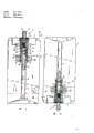
Fig. 1 represents to be equipped with the scheme drawing of an embodiment according to the present invention valve system, the atomizing cone part when normal use location.
The scheme drawing of atomizing cone reversing state in Fig. 2 presentation graphs 1.
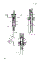
Fig. 3 to 5 schematically expresses other embodiments of the invention.
Fig. 1 is the scheme drawing according to an embodiment of aerosol valve device of the present invention.
Shown automiser spray comprises the common vessel 1 of a band valve disc 2, spray valve 3 and be connected on the spray valve and extend to raising pipe 4 near container bottom 5.In the ordinary course of things, spray valve comprises the valve body 6 that forms an inner chamber, and valve stamen element 7 is housed in this chamber, and the pressure that valve stamen element 7 is subjected to spring 10 makes it to contact with seal ring 8.Automiser spray also comprises a valve pipe 9 that has aperture 11, and it protrudes the outside of container and seal ring.Valve pipe 9 also is equipped with pushbutton switch usually, and the application force that can overcome spring 10 by means of this button will have the valve pipe of valve stamen element to be depressed, and aperture 11 just is communicated with the inner chamber of valve body as a result, and inner chamber is communicated with raising pipe 4 again.Like this, when the screw down valve pipe, the ejecta that is stored in the container can be discharged by raising pipe and valve.
Aerosol container when Fig. 1 has represented the normal position, promptly the bottom below, spray valve is in the above, and is as shown in arrow 12.
Under this state, as shown in the figure, injected ejecta 13 is stored in the bottom of container, when compressed propellant gas is in the top of ejecta 13, it applies a propellant pressure P to ejecta, in case spray valve work, as arrow 15 indications, propellant gas just promotes ejecta 13 and enters spray valve 3 by raising pipe 4.Ejecta just can amount discharge container like this, but propellant just can not because between the inlet of raising pipe passage and propellant gas, have by the formed hydraulic seal of ejecta.
Yet, if with this container lean or even turn around as shown in Figure 2, the hydraulic seal of raising pipe inlet is just no longer existed.At this moment, ejecta 13 is in the original top of container, makes the inlet of raising pipe have no obstacle.When spray valve was depressed, propellant can have no obstacle ground and discharge atomizing cone.The latter does not wish to take place very much, because it has reduced the pressure in the container, pressure even can hang down and make atomizing cone be unsuitable for re-using is although still have the ejecta of sufficient amount to be stored in the container.
According to the present invention, undesirable result above-mentioned can avoid by using a special valve, and Fig. 1 and 2 has schematically represented this embodiment.
Valve 16 is arranged between the end and spray valve away from the raising pipe 4 of bottom 5, has in fact formed a two-way valve, promptly be communicated with raising pipe and with hereinafter with a channel connection of the spray valve introduced.
Among the embodiment as shown in the figure, valve 16 comprises a valve body 17 that couples together with raising pipe.Valve body 17 integrally forms with valve body 6 in the present embodiment.Valve body 17 matches with adaptor union 18 in the bottom, and adaptor union is connected with raising pipe, and adaptor union 18 has a centre hole 19 to communicate with the raising pipe passage.The size in hole 19 strengthens and extends to valve body 17 at an end of adaptor union 18, to form the valve seat 20 that valve stamen element 21 is installed, adaptor union 18 links to each other with plug-in unit 22 in being installed in valve body 17, this plug-in unit has a centre hole equally, this is the extension in the wide hole of adaptor union, but this hole narrows down thereafter, and valve stamen element has been formed second valve seat 23.
In the outside of second valve seat, the hole that narrows down communicates with side opening 24, and side opening 24 is to be connected with the inside of container.Plug-in unit is contained on that end face that has groove 25 of adaptor union 18, and groove 25 communicates with inherent second groove 26 that vertically forms of plug-in unit, and second groove 26 communicates with the valve components inner chamber by the through hole 27 at valve components 6 intracavity bottoms.
Two valve seats 20,23 and the distance between the groove 25 between these two valve seats should be increased to and make valve stamen element all leave groove 25 fully at two bottom positions, and valve stamen element is in adaptor union 18 and is positioned at the position at top as shown in Figure 1.
At tip position shown in Figure 1, being connected between the interface channel between hole 19, the complete off center of valve stamen element and the groove 25, and at one time, side opening 24 and groove 25 is cut off.Therefore, when atomizing cone was worked, the propellant gas that is in container top was overflowed with regard to impassabitity groove 25, second groove 26 and valve 3.At this moment, ejecta is pushed into agent gas and discharges by raising pipe 4, hole 19, groove 25,26 and valve 3 by the aforementioned manner applied pressure.
Fig. 1 has represented position up required when normal operation, and valve stamen element 21 has born the pressure effect of gravity and the propellant gas by side opening 24, makes valve stamen element 21 tend to move down.The measure of having taked is guaranteed atomizing cone when rotine positioning, and valve stamen element keeps compressing top valve seat 23.
In the illustrated embodiment, for reaching this effect, around valve body 17 annular permanent magnnet 28 is installed, magnet 28 can move at the column part easy on and off of the valve body 17 between two convex shoulders 29 and 30, and, valve stamen element 21 is also made with permanent magnet, and circular magnet and magnet valves stamen element have opposite polarity.In the present embodiment, be the South Pole of magnetic if face toward the base of the circular magnet of bottom 5, the top margin that faces toward the valve stamen element of valve pocket also is the South Pole, so, the base of circular magnet top margin and valve stamen element just constitutes the arctic of magnetic.
When the normal position of atomizing cone, circular magnet drops on the following convex shoulder by gravity.In the present embodiment, convex shoulder 29 is made of the edge that exceeds the adaptor union 18 outside the valve body 17.Valve stamen element is owing to the tip position of the same pole effect of repelling each other shown in remaining in.
As shown in Figure 2, when atomizing cone turns around, because action of gravity, on the convex shoulder 30 under circular magnet is slipped to.Valve stamen element is repelled the position that top valve seat 20 maintenances compress by magnetic field.Under this state, ejecta 13 is stored in the part of container, normally at the top of container.In addition, under this state, groove 25 communicates with internal tank by centre hole and the side opening 24 in the plug-in unit 22.Like this, ejecta just can arrive groove 26 once more, arrives spray valve then.Propellant then can not arrive groove 25, seal up because side opening is ejected thing, and the passage that leads to raising pipe 4 has been closed by valve stamen element.
By the magnet that use two mutually to repel, make valve stamen element or press to a valve seat or press to another valve seat, the phenomenon of blocking in midway location or valve stamen can be avoided outward, has so just realized tangible on-off action.
The important point is two positions at valve stamen element, must seal up the passage that propellant gas may spray fully.
It should be noted that to read after the top description, those skilled in the art are easy to expect other various modified version.
Another method is mechanically to cause the crank motion of valve stamen element 21, to replace the circular magnet that can slidably reciprocate 28 of a given weight on certain distance.A weight gets up example as shown in Figure 3 by leverage and valve stamen combination of elements.
As shown in Figure 3, thin bar 35 connects with non magnetic valve stamen element 21, and the other end extends to raising pipe 4, links to each other with lever 36 1 ends, and the other end of lever 36 then is connected with weight 37.
Weight can constitute with different modes, for example, weight 37 raising pipe relatively slides up and down, also can be arranged to the circular magnet that is similar to around valve body 17, be connected with lever by pole extension downwards, structure as shown in Figure 4, weight that can move up and down 40 links to each other with the free end of lever 36 by connecting rod 41.Lever 36 is connected with valve stamen element by connecting rod 35 in raising pipe.
It should be noted that in the present embodiment, lever 36 be configured in raising pipe free-ended near, lever from the hole of raising pipe sidewall by and do not need vapor seal.
Yet if adopt the airtight passage of lever, it is a closing member that lever is said to valve stamen element.
According to another kind of modified version, magnet 28 can be used to cooperate with valve stamen element 21, and valve stamen element is not a permanent magnet, but can be magnetized.So, valve stamen element can be attracted by magnet, but the various passages in the valve body all should be made the change that adapts to this situation.
Fig. 5 has represented an example among this embodiment, and here magnet 28 also is arranged to and can moves up and down on valve body 17.In this case, it with as valve stamen element 21 compounding practices that are formed from steel, when atomizing cone remained on the upright position, magnet and valve stamen element were positioned at graphic extreme lower position.At this moment, valve stamen element 21 drops on the valve seat 20.Be stored in the container ejecta can by the hidden centre hole 19 in the other passage 50 of raising pipe 4, valve stamen element ', outside the passage 51 that links to each other with inner chamber with valve body 6 of upper valve base 23 is pressed towards.
Lower valve base communicates with side opening 52, but the propellant gas that sprays into side opening 52 is stopped up by valve stamen element when shown position.
When atomizing cone turns around, magnet 28 transposition, it is being with the motion of valve stamen element, when valve stamen element and valve seat 23 are kept in touch till, the position of the top that Here it is in Fig. 5.
After passage 50 was closed, ejecta can arrive the inner chamber of valve body 6 once more by side opening 52 and passage 53.Side opening 52 and passage 53 are owing to leaving of valve stamen element 21 is communicated with.
Further as can be seen, according to the present invention, the advantage of other of employing aerosol valve device is to make the container that has a kind of like this valve allow the composition that uses known atomizing cone to be not suitable for using, and can expect to use moisture ejecta.
Claims (9)
1, a kind of aerosol valve device, be specially adapted to automiser spray or other container, when using pressure gas as propellant, liquid can spray with fine mist from container, described valve system comprises a spray valve and raising pipe adaptor union, in working order down, raising pipe extends to the bottom near atomizing cone, a two-way valve is housed between spray valve and adaptor union, described two-way valve comprises the valve body that has center cavity, in this valve body, form two relative valve seats and be used for a core components that can between described valve seat, move around, described core components with a valve seat co-operating to be communicated with between raising pipe and the spray valve in the passage, close the peripheral direction of two-way valve and the passage between the spray valve, described core components and another valve seat co-operating to close between raising pipe and the spray valve in the passage, be communicated with the passage between two-way valve peripheral direction and the spray valve, it is characterized in that: have the fool proof drive that is used to handle described core components, it comes the control cock core element according to the residing position of container.
2, valve system as claimed in claim 1, it is characterized in that, core components is to be made by magnetizable material, fool proof drive comprises an element that is arranged in around the two-way valve valve body, this element to small part has permanent magnet type, and can slide along the cooresponding valve body of the passage between these two valve seats.
3, valve system as claimed in claim 2 is characterized in that, core components is a supported permanent magnet, so that core components and the described element repulsion mutually each other that has permanent magnet type to small part.
As claim 2 or 3 described valve systems, it is characterized in that 4, the element with permanent magnet type is a circular magnet around valve body, and can move along the housing between two protruding arms.
5, valve system as claimed in claim 1, it is characterized in that, core components extends in the raising pipe with one and manages free-ended thin bar connection near this, and thin bar is connected with an end of lever away from an end of core components, and the other end of described lever then is connected with a weight.
6, valve system as claimed in claim 5 is characterized in that, this weight can move along raising pipe or valve body.
7, as claim 1 or 5 described valve systems, it is characterized in that, the valve body of two-way valve is a cylindrical body that is connected with the spraying valve body, insert adaptor union or raising pipe at a end away from the spraying valve body, it is connected with a plug-in unit that inserts cylindrical body, in plug-in unit, form a valve seat, and in adaptor union, form another valve seat.
8, valve system as claimed in claim 7, it is characterized in that plug-in unit and adaptor union define between two valve seats and the centre hole that stretches out and be communicated with raising pipe jointly, centre hole is outside the valve seat that nestles up the spraying valve body, be connected with the valve body periphery by side opening, plug-in unit has formed the side opening between two valve seats, side opening is connected with the passage that is parallel to centre hole, and then is communicated with the spraying valve body.
9, according to the formed automiser spray of the described aerosol valve device of above arbitrary claim.
Applications Claiming Priority (2)
| Application Number | Priority Date | Filing Date | Title |
|---|---|---|---|
| NL8800774 | 1988-03-28 | ||
| NL8800774A NL8800774A (en) | 1988-03-28 | 1988-03-28 | AEROSOL VALVE DEVICE. |
Publications (2)
| Publication Number | Publication Date |
|---|---|
| CN1040003A CN1040003A (en) | 1990-02-28 |
| CN1018172B true CN1018172B (en) | 1992-09-09 |
Family
ID=19852015
Family Applications (1)
| Application Number | Title | Priority Date | Filing Date |
|---|---|---|---|
| CN89102812A Expired CN1018172B (en) | 1988-03-28 | 1989-03-28 | Aerosol valve device |
Country Status (10)
| Country | Link |
|---|---|
| US (1) | US5005738A (en) |
| EP (1) | EP0335457B1 (en) |
| JP (1) | JPH029467A (en) |
| KR (1) | KR890014172A (en) |
| CN (1) | CN1018172B (en) |
| BR (1) | BR8901393A (en) |
| DE (1) | DE68906813T2 (en) |
| ES (1) | ES2046442T3 (en) |
| NL (1) | NL8800774A (en) |
| ZA (1) | ZA892267B (en) |
Families Citing this family (20)
| Publication number | Priority date | Publication date | Assignee | Title |
|---|---|---|---|---|
| FR2688286B1 (en) * | 1992-03-04 | 1995-06-16 | Oreal | THREE-WAY VALVE. |
| US5350088A (en) * | 1993-09-13 | 1994-09-27 | Summit Packaging Systems, Inc. | Invertible aerosol valve |
| DE19609181A1 (en) * | 1996-03-09 | 1997-09-11 | Pfeiffer Erich Gmbh & Co Kg | Discharge device for media |
| US5850947A (en) * | 1996-07-15 | 1998-12-22 | Kim; Phillip S. | Invertible and multi-directional fluid delivery device |
| US5799681A (en) * | 1997-05-14 | 1998-09-01 | Mallard Products, Inc. | Safety shut off valve and method of automatic flow restoration |
| WO2000035591A1 (en) * | 1998-12-15 | 2000-06-22 | Kim Phillip S | Draw tube assembly for containers |
| ATE308470T1 (en) | 1999-03-12 | 2005-11-15 | Glaxo Group Ltd | DOSSIER VALVE |
| FR2833584B1 (en) * | 2001-12-13 | 2004-04-23 | Valois Sa | FLUID PRODUCT DISTRIBUTION VALVE AND FLUID PRODUCT DISPENSING DEVICE HAVING SUCH A VALVE |
| CN100370259C (en) * | 2004-11-12 | 2008-02-20 | 中国科学院西安光学精密机械研究所 | Tracing particle high-speed jettison device in waterflow field particle imaging velocity measuring system |
| FR2888822B1 (en) * | 2005-07-21 | 2010-04-02 | Valois Sas | FLUID PRODUCT DELIVERY VALVE |
| JP5119521B2 (en) * | 2007-01-31 | 2013-01-16 | イーペーエス リサーチ アンド ディヴェロップメント ベスローテン フェンノートシャップ | Metering device for dispensing a dose of pressurized fluid |
| FR2976506A1 (en) * | 2011-06-15 | 2012-12-21 | Chanel Parfums Beaute | DEVICE FOR DISPENSING A FLUID PRODUCT FOR CARE, MAKE-UP OR TOILET |
| US8695858B2 (en) * | 2011-09-07 | 2014-04-15 | Achim Philipp Zapp | Air valves for a wireless spout and system for dispensing |
| US8881956B2 (en) * | 2012-02-29 | 2014-11-11 | Universidad De Sevilla | Dispensing device and methods for emitting atomized spray |
| CN105889586B (en) * | 2016-06-17 | 2017-12-01 | 湖南科技学院 | A kind of constant pressure automatic pressure regulating device |
| US10661974B2 (en) * | 2016-08-12 | 2020-05-26 | The Procter & Gamble Company | Internally fitted aerosol dispenser |
| US10618152B2 (en) * | 2017-08-09 | 2020-04-14 | Black & Decker Inc. | All-direction valve and handheld power tool having same |
| CN108100435A (en) * | 2017-10-09 | 2018-06-01 | 佛山赛唯莱特智能设备有限公司 | A kind of novel house Architectural Equipment |
| CN108082696A (en) * | 2017-10-09 | 2018-05-29 | 佛山智敏电子科技有限公司 | A kind of improved electric cable device |
| CN108082680A (en) * | 2017-10-09 | 2018-05-29 | 佛山赛唯莱特智能设备有限公司 | A kind of modified building equipment |
Family Cites Families (17)
| Publication number | Priority date | Publication date | Assignee | Title |
|---|---|---|---|---|
| US2068428A (en) * | 1933-04-17 | 1937-01-19 | Link Belt Co | Settling tank |
| US2629401A (en) * | 1947-10-08 | 1953-02-24 | Hays Mfg Co | Magnetically controlled packless valve |
| US2793794A (en) * | 1955-03-25 | 1957-05-28 | Gulf Research Development Co | Eduction valve for pressure discharge dispensers |
| US2904229A (en) * | 1957-12-11 | 1959-09-15 | Gulf Research Development Co | Aerosol dispensers and like pressurized packages |
| US2968428A (en) * | 1959-02-26 | 1961-01-17 | Gulf Research Development Co | Gravity actuated valves for pressurized dispensers |
| US3018023A (en) * | 1959-02-27 | 1962-01-23 | Rudolph D Talarico | Fluid dispensing apparatus |
| AT233341B (en) * | 1961-09-04 | 1964-05-11 | Kromschroeder Ag G | Valve |
| US3447551A (en) * | 1967-06-14 | 1969-06-03 | Arthur R Braun | Upside-downside aerosol dispensing valve |
| US3733013A (en) * | 1970-12-22 | 1973-05-15 | Sterling Drug Inc | Double dip tube aerosol |
| US3893596A (en) * | 1974-02-25 | 1975-07-08 | Vca Corp | Upright-inverted aerosol dispenser |
| US3983890A (en) * | 1975-06-09 | 1976-10-05 | Robertshaw Controls Company | Roll over valve construction and method of making the same |
| FR2410775A1 (en) * | 1977-12-05 | 1979-06-29 | Peugeot Cycles | CLOSING DEVICE FOR FLUID PIPING |
| US4261485A (en) * | 1979-12-04 | 1981-04-14 | Raymond Borg | Automatic bottle cap having a magnetically actuated valve |
| DE3025725C2 (en) * | 1980-07-08 | 1985-11-07 | Deutsche Präzisions-Ventil GmbH, 6234 Hattersheim | Spray valve assembly |
| US4572406A (en) * | 1983-03-07 | 1986-02-25 | Seachem, A Division Of Pittway Corp. | Aerosol container and valve assembly for automatically signalling depletion of a predetermined amount of the container contents when in an inverted position |
| FR2551828B1 (en) * | 1983-09-12 | 1986-08-08 | Valvole Aerosol Res Italia | RETURNABLE VALVE FOR THE DISPENSING OF PRESSURIZED LIQUID |
| DE3436984A1 (en) * | 1984-10-09 | 1986-04-17 | Erich H. Dipl.-Ing. 4950 Minden Woltermann | MACHINE FOR PREPARING HOT DRINKS WITH DOSED LIQUID REMOVAL |
-
1988
- 1988-03-28 NL NL8800774A patent/NL8800774A/en not_active Application Discontinuation
-
1989
- 1989-03-23 DE DE1989606813 patent/DE68906813T2/en not_active Expired - Lifetime
- 1989-03-23 ES ES89200750T patent/ES2046442T3/en not_active Expired - Lifetime
- 1989-03-23 EP EP19890200750 patent/EP0335457B1/en not_active Expired - Lifetime
- 1989-03-27 KR KR1019890003852A patent/KR890014172A/en not_active Application Discontinuation
- 1989-03-27 US US07/328,568 patent/US5005738A/en not_active Expired - Fee Related
- 1989-03-27 BR BR8901393A patent/BR8901393A/en not_active IP Right Cessation
- 1989-03-28 CN CN89102812A patent/CN1018172B/en not_active Expired
- 1989-03-28 ZA ZA892267A patent/ZA892267B/en unknown
- 1989-03-28 JP JP1077966A patent/JPH029467A/en active Granted
Also Published As
| Publication number | Publication date |
|---|---|
| CN1040003A (en) | 1990-02-28 |
| NL8800774A (en) | 1989-10-16 |
| BR8901393A (en) | 1989-11-07 |
| ES2046442T3 (en) | 1994-02-01 |
| ZA892267B (en) | 1989-12-27 |
| JPH029467A (en) | 1990-01-12 |
| EP0335457A2 (en) | 1989-10-04 |
| EP0335457B1 (en) | 1993-06-02 |
| EP0335457A3 (en) | 1990-01-10 |
| DE68906813D1 (en) | 1993-07-08 |
| JPH0534066B2 (en) | 1993-05-21 |
| KR890014172A (en) | 1989-10-23 |
| US5005738A (en) | 1991-04-09 |
| DE68906813T2 (en) | 1993-10-14 |
Similar Documents
| Publication | Publication Date | Title |
|---|---|---|
| CN1018172B (en) | Aerosol valve device | |
| US5301841A (en) | Media discharge apparatus for housing a movable reservoir | |
| US4191313A (en) | Trigger operated dispenser with means for obtaining continuous or intermittent discharge | |
| EP0722783B1 (en) | Liquid jet blower | |
| JP2723487B2 (en) | Injection valve and injection device provided with this valve | |
| US6070770A (en) | Aerosol flow regulator | |
| KR100228660B1 (en) | Piston dispensing apparatus | |
| JPH02503488A (en) | pressure regulator | |
| US3777945A (en) | Spraying device | |
| CA1230867A (en) | Dispensing pump adapted for pressure filling | |
| KR100517094B1 (en) | Valve for pressurized containers | |
| US4053089A (en) | Pump for dispensing liquids | |
| US6808159B1 (en) | Non-refillable valve | |
| CA1054984A (en) | Dispensing device | |
| CA2088231C (en) | Pump dispensers | |
| CA2076363C (en) | Dispensing apparatus | |
| GB1164251A (en) | Valve Construction for Pressurised Dispensers. | |
| KR880007957A (en) | Fire extinguishing valve | |
| EP1033174B8 (en) | Manually operated pump for dispensing liquids under pressure | |
| GB1313881A (en) | Discharge valve assembly for pressurised dispensing container | |
| EP0484616A1 (en) | Manually operated pump device for dispensing fluids | |
| US3545720A (en) | Tilt valve | |
| GB2233395A (en) | Improvements in or relating to aerosol type dispensers. | |
| JP2023107058A (en) | Re-pressurizing system and method of re-pressurizing ejective container | |
| JPS60220202A (en) | Pressure accumulator |
Legal Events
| Date | Code | Title | Description |
|---|---|---|---|
| C06 | Publication | ||
| PB01 | Publication | ||
| C10 | Entry into substantive examination | ||
| SE01 | Entry into force of request for substantive examination | ||
| C13 | Decision | ||
| GR02 | Examined patent application | ||
| C14 | Grant of patent or utility model | ||
| GR01 | Patent grant | ||
| C19 | Lapse of patent right due to non-payment of the annual fee | ||
| CF01 | Termination of patent right due to non-payment of annual fee |