CN101806948B - Focus adjusting apparatus and focus adjusting method - Google Patents
Focus adjusting apparatus and focus adjusting method Download PDFInfo
- Publication number
- CN101806948B CN101806948B CN2010101170618A CN201010117061A CN101806948B CN 101806948 B CN101806948 B CN 101806948B CN 2010101170618 A CN2010101170618 A CN 2010101170618A CN 201010117061 A CN201010117061 A CN 201010117061A CN 101806948 B CN101806948 B CN 101806948B
- Authority
- CN
- China
- Prior art keywords
- focus
- focusing lens
- moving range
- frame
- subject
- Prior art date
- Legal status (The legal status is an assumption and is not a legal conclusion. Google has not performed a legal analysis and makes no representation as to the accuracy of the status listed.)
- Active
Links
Images


Classifications
-
- G—PHYSICS
- G02—OPTICS
- G02B—OPTICAL ELEMENTS, SYSTEMS OR APPARATUS
- G02B7/00—Mountings, adjusting means, or light-tight connections, for optical elements
- G02B7/28—Systems for automatic generation of focusing signals
- G02B7/36—Systems for automatic generation of focusing signals using image sharpness techniques, e.g. image processing techniques for generating autofocus signals
-
- H—ELECTRICITY
- H04—ELECTRIC COMMUNICATION TECHNIQUE
- H04N—PICTORIAL COMMUNICATION, e.g. TELEVISION
- H04N23/00—Cameras or camera modules comprising electronic image sensors; Control thereof
- H04N23/60—Control of cameras or camera modules
- H04N23/67—Focus control based on electronic image sensor signals
- H04N23/675—Focus control based on electronic image sensor signals comprising setting of focusing regions
-
- G—PHYSICS
- G03—PHOTOGRAPHY; CINEMATOGRAPHY; ANALOGOUS TECHNIQUES USING WAVES OTHER THAN OPTICAL WAVES; ELECTROGRAPHY; HOLOGRAPHY
- G03B—APPARATUS OR ARRANGEMENTS FOR TAKING PHOTOGRAPHS OR FOR PROJECTING OR VIEWING THEM; APPARATUS OR ARRANGEMENTS EMPLOYING ANALOGOUS TECHNIQUES USING WAVES OTHER THAN OPTICAL WAVES; ACCESSORIES THEREFOR
- G03B13/00—Viewfinders; Focusing aids for cameras; Means for focusing for cameras; Autofocus systems for cameras
- G03B13/32—Means for focusing
- G03B13/34—Power focusing
- G03B13/36—Autofocus systems
-
- H—ELECTRICITY
- H04—ELECTRIC COMMUNICATION TECHNIQUE
- H04N—PICTORIAL COMMUNICATION, e.g. TELEVISION
- H04N23/00—Cameras or camera modules comprising electronic image sensors; Control thereof
- H04N23/60—Control of cameras or camera modules
- H04N23/61—Control of cameras or camera modules based on recognised objects
- H04N23/611—Control of cameras or camera modules based on recognised objects where the recognised objects include parts of the human body
Landscapes
- Engineering & Computer Science (AREA)
- Multimedia (AREA)
- Signal Processing (AREA)
- Physics & Mathematics (AREA)
- General Physics & Mathematics (AREA)
- Computer Vision & Pattern Recognition (AREA)
- Optics & Photonics (AREA)
- Studio Devices (AREA)
- Automatic Focus Adjustment (AREA)
- Focusing (AREA)
Abstract
There are provided a focus adjusting apparatus and method in which judgment of an object area to be focused can be favorably performed when the judgment of the object area to be focused is executed at the time of image-taking preparation operation. In the focus adjusting apparatus and method, a first operation of determining the object area to be focused is performed prior to the image-taking preparation operation, and a second operation different from the first operation is performed to execute a focusing operation at the time of the image-taking preparation operation. Prior to the first operation, whether or not an object to be focused can be predicted is judged to change a manner of the first operation based on a result of a judgment.
Description
Technical field
The present invention relates to focus adjusting apparatus and focus adjusting method.The invention particularly relates to the auto-focus regulation technology.
Background technology
Usually, carry out in electronic stills camera and video camera in the situation of automatic focusing (AF), use a kind of like this method: the lens position of the radio-frequency component maximum of the luminance signal that the imaging apparatuss such as CCD (charge-coupled device (CCD)) are provided is as focusing (in-focus) position.Following scan method is considered to this class methods.In this scan method, when the whole moving range at lens drives these lens, the evaluation of estimate (focus evaluated value) that Coutinuous store calculates based on the radio-frequency component of the luminance signal that obtains from imaging apparatus, and the evaluation of estimate that will store like this shows as peaked lens position as focusing position.
In other method, continuous moving lens on the direction that focus evaluated value increases.The method is called hill climbing method (hereinafter also being called continuous AF).
In addition, Japan No. 4106485 patent disclosure following methods.In the method, before the indication that is used for the shooting beamhouse operation, carry out continuous AF keeping focusing state, thereby be limited in the moving range for the focusing lens that moves by the AF scan method for the beamhouse operation of making a video recording after the indication of shooting beamhouse operation.Therefore, shortened the AF running time.
In continuous AF, in the situation of mobile lens on the direction that focus evaluated value increases, unless in the plane of delineation, identify or determine the zone that will focus on, focusing on otherwise can not carry out the subject that will focus on.
In the method for above-mentioned Jap.P., above-mentioned scan method is combined with acceleration focusing operation with continuous AF.Yet, the subject (main subject) that will focus on the plane of delineation that the user wants to focus on is not identified.Therefore, according to the situation of shooting scene, existence can not be carried out the possibility that focuses on to the subject that will focus on.
Summary of the invention
According to the present invention, a kind of focus adjusting apparatus comprises: receiving element is used for receiving the indication that is used for focal adjustments; Image unit is used for making a video recording with output image data by the subject image of focusing lens input; Setting unit is used for arranging the focus detection zone; And focal adjustments unit, be used in mobile described focusing lens, detecting the focus signal of the focus state of focusing lens described in the described focus detection of the expression zone, in preset range, to regulate the position of described focusing lens based on described focus signal, wherein, described focal adjustments unit controls the first operation and the second operation, described the first operation is for detecting the subject zone of described focus signal to determine to focus on before receiving described indication, described the second operation detects described focus signal to carry out the focal adjustments of described focusing lens for the information based on the determined subject zone that will focus on when receiving described indication; And described focal adjustments unit judged whether to predict the subject that will focus on before described the first operation, to change the mode of described the first operation based on judged result.
According to the present invention, a kind of focus adjusting method for the control focus adjusting apparatus, described focus adjusting apparatus comprises image unit, described image unit is used for making a video recording with output image data by the image of focusing lens input, described focus adjusting method may further comprise the steps: carry out an AF scan operation, a described AF scan operation is used for carrying out when moving described focusing lens before the shooting beamhouse operation and the position of described focusing lens obtains extraction unit explicitly in the scan operation of the output signal in set focus detection zone; And determine that the subject that will focus on is regional; Be different from the 2nd AF scan operation of a described AF scan operation, described the 2nd AF scan operation is for the scan operation of carrying out focusing when described shooting beamhouse operation and operating; And judge whether to predict the subject that will focus on before the described AF scan operation carrying out, to change the mode of a described AF scan operation based on judged result.
By below with reference to the explanation of accompanying drawing to exemplary embodiments, further feature of the present invention will be apparent.
Description of drawings
Fig. 1 is that explanation is according to the block diagram of the structure of the embodiment of focus adjusting apparatus of the present invention;
Fig. 2 is the process flow diagram that the focal adjustments operation of this embodiment is shown;
Fig. 3 is the process flow diagram that the subroutine of the AF scan operation when face detects among Fig. 2 is shown;
Fig. 4 is the process flow diagram that the subroutine of the focusing judgement among Fig. 3, Fig. 9 and Figure 12 is shown;
Fig. 5 is the figure of the mode of the focusing judgement in the key diagram 4;
Fig. 6 is the process flow diagram that the subroutine of the identification of the zone of subject among Fig. 2 or definite AF scanning is shown;
Fig. 7 is the figure of the example of the AF frame setting in the key diagram 6;
Fig. 8 is the process flow diagram that the subroutine of the AF scanning of using with reference to last operation judges among Fig. 6 is shown;
Fig. 9 is the process flow diagram that the subroutine of Figure 10 of the first embodiment and the main subject region decision among Figure 11 is shown;
Figure 10 A~10C is the figure of the main subject region decision in the key diagram 9;
Figure 11 is the process flow diagram that the subroutine of the regional AF scanning among Fig. 6 is shown;
Figure 12 is the process flow diagram that the subroutine of the area update judgement among Figure 11 is shown;
Figure 13 A and 13B are the figure of the example of the area update judgement among explanation Figure 12;
Figure 14 is the process flow diagram that the subroutine of the focusing driving among Fig. 6 is shown;
Figure 15 is the process flow diagram that the subroutine of the continuous AF among Fig. 2 is shown;
Figure 16 is the process flow diagram that the subroutine of the shooting processing among Fig. 2 is shown;
Figure 17 is the process flow diagram that the subroutine of the AF operation that is used for final exposure among Figure 16 is shown;
Figure 18 is the process flow diagram that the subroutine of Figure 10 of the second embodiment and the main subject region decision among Figure 11 is shown.
Embodiment
The below describes each embodiment of the present invention with reference to the accompanying drawings in detail.
Fig. 1 illustrates the structure that has according to the camera of the embodiment of focus adjusting apparatus of the present invention.
In Fig. 1, Reference numeral 101 expressions comprise the pick-up lens of zoom mechanism.Reference numeral 102 expressions are used for the aperture/shutter of control incident light quantity.Reference numeral 103 expressions comprise the AE handling part for the drive division that drives aperture/shutter.Reference numeral 104 expressions are for the focusing lens that following imaging apparatus is focused.Reference numeral 105 expressions comprise the AF handling part for the drive division of focusing lens 104.Reference numeral 106 expression electronic flash unit.Reference numeral 107 expression electronic flash (EF) handling parts.
The image processing part that Reference numeral 110 expression is used for carrying out following processing and other processing: calculate the luminance signal of subject and extract signal content in the special frequency band of luminance signal to obtain focus evaluated value according to the output signal of imaging apparatus.Reference numeral 111 expression WB (white balance) handling parts.Reference numeral 112 presentation format converter sections.
The high speed internal memorys (also being called DRAM) such as Reference numeral 113 expression random access memory.Can use DRAM 113 as the cache memory that is used for temporarily storing image data or be used for the working storage of image compression/decompression.Reference numeral 114 expression comprises the recording image section of the recording medium such as storage card and interface thereof.Reference numeral 115 expressions are used for the systems control division (CPU) in operation control whole systems such as shooting sequences.Reference numeral 116 expressions are used for the storer (VRAM) that image shows.Reference numeral 117 expression operation display part, this operation display part not only shows image, but also shows indication, the camera picture when representing the indication of camera state and representing shooting or the indication in the plane of delineation and focus detection zone of non-productive operation.
In addition, as the method that works out practical application, there is the method for use wavelet transformation and image feature amount etc.The quantity of the pixel that can count to get in facial zone (facial coordinate) according to the information based on the face that detects is judged facial size.Can also judge in the following way facial size: the information (eye positional information) based on the face that detects is calculated the distance between the eye, to use the eye distance that obtains in advance from making table with the statistical relationship of facial size (quantity of pixel).Can also calculate by the coordinate figure according to four angles (ad-hoc location) of face the quantity of the pixel in the facial zone and judge facial size.
The mobile subject detection of Reference numeral 124 expressions section, whether this moves subject detection section mobile for detection of the subject in the plane of delineation or background, and mobile subject information is provided to CPU 115.More specifically, two images by the time series arrangement in the picture signal after will being processed by image processing part 110 compare mutually, and according to the different information of comparative result, detect the mobile subject information (amount of movement, position and scope) of subject/background.Reference numeral 125 expression angular-rate sensors, this angular-rate sensor are for detection of the angular velocity of camera, and the information of camera motion is provided to CPU 115.By using angular-rate sensor, can also detect the attitude (that is, perpendicular attitude or horizontal attitude) of camera.
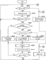
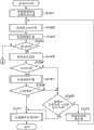
Operation with reference to the Electrofax of the flowchart text present embodiment of Fig. 2.At step S201, CPU 115 judges the state (ON/OFF) that is used to indicate the SW1 that carries out the shooting preparation.When this state was ON, step entered step S212.When this state was OFF, step entered step S202.At step S202, judge scene stability.At step S203, check the judgement of stability of the shooting scene among the step S202.When judging the shooting scene when stablizing, step enters step S204.When judging the shooting scene when unstable, step is back to step S201.Here, the steady state (SS) of shooting scene is that subject and the camera that will take keeps stable so that the state that can suitably make a video recording.For example, when the amount of movement of the camera that detects by angular-rate sensor 125 during less than specified quantitative, can think that the state of camera is stable.
At step S204, check that subject brightness is whether below particular value.When subject brightness during less than particular value, step enters step S205.If subject brightness is not less than particular value, then step enters step S206.At step S205, carry out the AF frame setting of low-light level.Here, the AF frame is the zone that obtains focus evaluated value in the plane of delineation.In addition, focus evaluated value is will convert from the simulation drawing picture signal that imaging apparatus 108 reads digital signal to and extract the value that the high-frequency signal composition of luminance signal obtains by image processing part 110 from this digital signal by A/D converter section 109.The position of this evaluation of estimate and focusing lens 104 and AF frame is stored among the CPU 115 accordingly.Obtaining focus evaluated value refers to read the focus evaluated value that is stored among the CPU 115 for the judgement in the AF control of AF handling part 105.When brightness is low, possible prolonging exposure time.Therefore, in AF scanning, almost can not guarantee sufficient AF precision.Therefore, in the present embodiment, when brightness is hanged down, omit the identification in subject zone or the scanning of determining and being used for facial detection, and the single AF frame with specific size is set near the middle body of the plane of delineation.
At step S206, face detection module 123 checks whether detect face.When detecting face, step enters step S207.If do not detect face, then step enters step S208.At step S207, the AF scanning (referring to Fig. 3) when carrying out facial the detection according to following process.Then, step enters step S209.At step S208, carry out for the AF scanning (referring to Fig. 6) of determining the subject zone according to following process.At step S209, carry out continuous AF (referring to Figure 15) according to following process.
Here, alternatively, can in the situation of not carrying out continuous AF, only carry out once the focusing operation relevant with determined subject zone, perhaps can only determine the subject zone.In this case, step is carried out the second scan operation then subsequently.
At step S210, carry out the scene instability and judge.At step S211, check that it is unsettled whether judging the shooting scene in step S210.When to judge scene be unsettled, step entered step S201.Be not unsettled if judge scene, then step enters step S209.Here, the non-steady state of shooting scene is the state labile of subject or camera so that the state that can not finish suitable shooting.For example, the amount of movement of the camera that is detected by angular-rate sensor 125 is greater than specified quantitative, perhaps with respect to the brightness variable quantity of last brightness greater than specified quantitative, the facial detected state that is perhaps detected by face detection module 123 (that is, detecting or do not detect face) changes.In this case, judge shooting scene change (that is, scene is unstable).
When the state of the SW1 that is used to indicate the shooting preparation was in ON, step entered step S212 from step S201.At step S212, the focus level judgement symbol is set to FALSE (vacation).At step S213, according to the processing (referring to Figure 16) of making a video recording of following process.
In aforesaid operations, AE handling part 103 is based on the control signal control aperture/shutter 102 from CPU 115.Operate to make the brightness that is presented at the image on the operation display part 117 suitable by this AE that is used for control AE handling part 103.
Fig. 3 is the process flow diagram of the AF scanning of the face in the step S 207 of Fig. 2 when detecting.At step S401, based on the facial information that is detected by face detection module 123 (position and size) the AF frame is set.At step S402, AF handling part 105 moves to the scanning starting position with focusing lens 104.Here, for example based on according to the facial size that detects estimated that go out and the distance subject personage, determine the scanning starting position.At step S403, CPU 115 is stored in the focus evaluated value corresponding with the current location of focusing lens 104 among the DRAM 113.At step S404, CPU 115 obtains the data of the current location of focusing lens 104, and the data of current location are stored among the DRAM 113.Therefore, before an AF scan operation that is used for definite subject zone that will focus on, control module is based on the testing result that is obtained by face-detecting unit, the scope that the subject zone that judgement will focus on may exist.Then, based on this judged result, adjust the mode (following AF frame set-up mode, scanning position and scope etc.) of an AF scan operation.
At step S405, CPU 115 judges the state (ON/OFF) of the SW1 that is used to indicate the shooting preparation.When this state is ON, finish and work as pre-treatment, and step enters the step S212 among Fig. 2.When this state was OFF, step entered step S406.At step S406, carry out scene change and judge.Scene change judges it is to judge the processing whether the shooting scene changes according to the state of subject or camera.
At step S407, CPU 115 checks whether the current location of focusing lens 104 is consistent with scan end position.When both were consistent, step entered step S409.If inconsistent, then step enters step S408.Here, for example based on according to the facial size that detects estimated that go out and the distance subject personage, determine scan end position.At step S408, AF handling part 105 moves specified quantitative with focusing lens 104 to scan end position, and then, step is back to step S403.At step S409, carry out focusing according to following process and judge (referring to Fig. 4).
At step S410, check the focusing among the step S409 judges whether it is zero-judgement.When the focusing judgement was zero-judgement, step entered step S411.If not, then step enters step S414.Here, when the contrast of subject is fully and subject when being present in the scanning distance scope, make zero-judge.
At step S411, calculate the focusing position of the focus evaluated value maximum that obtains at step S403.At step S412, AF handling part 105 moves to focusing lens 104 focusing position that calculates at step S411.At step S413, be TRUE (very) with the peak value detection flag.Be FALSE with the peak value detection flag in advance.
At step S414, owing to judge it is not zero-judgement, the contrast that is subject is inadequate or subject is present in outside the scanning distance scope, thereby AF handling part 105 moves to pre-stored position (point of fixity) in DRAM 113 with focusing lens 104.What here, point of fixity was set to subject exists the high distance of possibility.For example, if detect people's face, then point of fixity is the distance according to the estimated people who goes out of the facial size that detects.
The subroutine of judging below with reference to the step S1201 among the step S409 in Fig. 4 and Fig. 5 key diagram 3 and following Fig. 9 and the focusing among the step S1501 among Figure 12.
Represent that at transverse axis focusing lens position and the longitudinal axis represent in the situation of focus evaluated value, except the situation of conflict that has far and near subject etc., focus evaluated value is with the form of as shown in Figure 5 chevron and change.Therefore, can judge chevron by having greater than the length of the sloping portion of the degree of tilt of particular value (Slope Thr) and slope or the degree of tilt of this sloping portion according to poor, inclination between maximum focus evaluated value and the minimum focus evaluated value, carry out to focus on and judge.
Provide the result that focus on to judge as following zero-judge and *-judge.
Zero-to judge: the contrast of subject is fully, and subject is present in the scanning distance scope.
*-judge: the contrast of subject is inadequate, and perhaps subject is present in outside the scanning distance scope.
In addition, *-in judging, be present in subject in the extraneous situation of scanning distance of wide-angle side, use △-judgement.
With reference to Fig. 5 the length L of the above-mentioned sloping portion that is used for the judgement chevron and the slope S L/L of this sloping portion are described.SL represents the mountain height of sloping portion.Point D and some E represent to think the point that (some A) begin to continue to that tilts from the hilltop, and L is a D and the mountain width of putting between the E.Can think that the scope that tilts to continue is the scope of the continued presence focus evaluated value analyzing spot above than the low specified quantitative (SlopeThr) of focus evaluated value at some A place.Analyzing spot be with focusing lens from scanning starting point continuous moving to end of scan point during the point of acquisition focus evaluated value.Above-mentioned SL equals SL1+SL2, and wherein, SL1 is poor between the focus evaluated value at a focus evaluated value at A place and some D place, and SL2 is poor between a focus evaluated value at A place and the focus evaluated value of putting the E place.
In the process flow diagram of Fig. 4, at step S601, obtain maximal value and the minimum value of focus evaluated value.Then, at step S602, obtain the analyzing spot of focus evaluated value maximum, and step enters step S603.At step S603, obtain for the L and the SL that judge chevron according to analyzing spot and focus evaluated value, and step enters step S604.
At step S604, judge that chevron is whether in the wide angle side end that tilts.Affirmative determination for tilting in wide angle side and finishing should satisfy following two conditions.The analyzing spot that condition is the focus evaluated value maximum appears at the wide-angle side in the specific sweep limit.Another condition is that difference between the focus evaluated value of focus evaluated value and the position analyzing spot from the wide-angle side towards the point of side shifting of dolly-out,ing dolly-back at analyzing spot place of wide-angle side is greater than particular value.When being made at wide angle side and tilting the affirmative determination that finishes, step enters step S609.If be not made at the affirmative determination that wide angle side tilts and finishes, then step enters step S605.
At step S605, judge that chevron is whether in the side direction of the dolly-out,ing dolly-back end that tilts.Affirmative determination for tilting in the side direction of dolly-out,ing dolly-back and finishing should satisfy following two conditions.The analyzing spot that condition is the focus evaluated value maximum appears at the side of dolly-out,ing dolly-back in the specific sweep limit.Another condition be dolly-out, dolly-back the focus evaluated value at analyzing spot place of side and position from the side of dolly-out,ing dolly-back towards the difference between the focus evaluated value of the analyzing spot of a point of wide-angle side shifting greater than particular value.When being made at the side direction of dolly-out,ing dolly-back and tilting the affirmative determination that finishes, step enters step S608.If be not made at the affirmative determination that the side direction of dolly-out,ing dolly-back tilts and finishes, then step enters step S606.
At step S606, degree of tilt greater than the length L of the sloping portion of particular value more than the particular value, the mean value SL/L of the degree of tilt of sloping portion more than the particular value and the difference between maximum (Max) and minimum (Min) focus evaluated value in the situation more than the particular value, step enters step S607.If not, then step enters step S608.At step S607, because the focus evaluated value that obtains has chevron, subject has contrast, and can focus on judgement, thereby judge the result and be zero-judge.At step S608, because the focus evaluated value that obtains does not have chevron, subject does not have contrast, and can not focus on judgement, thus judge the result for *-judge.At step S609, although because the focus evaluated value that obtains does not have chevron, existence is inclined upwardly towards the wide-angle side, and peak value might be present in the wide-angle side, thereby to judge the result be △-judgement.Focus on like this judgement.
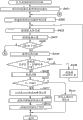
Fig. 6 is subject zone identification among the step S208 of Fig. 2 or the process flow diagram of definite AF scanning.Here, carry out for the AF scanning of determining the main subject zone on the plane of delineation.
At step S801, check whether carry out electronic zoom.When carrying out electronic zoom, step enters step S802.If do not carry out electronic zoom, then step enters step S803.At step S802, carry out the AF frame setting for electronic zoom.Here, in electronic zoom, enlarge the middle section of the plane of delineation, and the zone after will enlarging is presented on the operation display part 117.At this moment, owing to enlarged narrow zone on the imaging apparatus 108, thereby consist of the image that is presented on the operation display part 117 by the pixel of the pixel quantity of the image of quantity when not carrying out electronic zoom.Therefore, if carry out the setting of AF frame to be presented at the frame ratio that frame ratio in the image on the operation display part 117 is presented at when not carrying out electronic zoom in the image on the operation display part 117 during electronic zoom identical, the pixel quantity in the AF frame when not carrying out electronic zoom that becomes of the pixel quantity in the AF frame when then carrying out electronic zoom.Therefore, when electronic zoom, the signal to noise ratio (S/N ratio) of focus evaluated value reduces.When therefore, the AF frame being arranged on carry out electronic zoom and different between when not carrying out electronic zoom.In the present embodiment, when electronic zoom, the single AF frame with specific size is set near the middle body of the plane of delineation.
At step S803, at the plane of delineation N * N AF frame is set.For example, N=5 and AF frame in the horizontal direction with vertical direction on length be set to the plane of delineation in the horizontal direction with vertical direction on 10% situation of length under, the AF frame is set as shown in Figure 7.Can consider that the possibility that exists of main subject arranges N or AF frame size in the plane of delineation.In addition, can make the AF frame in the horizontal direction with vertical direction on quantity mutually different.
At step S804, carry out the judgement with reference to last operation.With reference in the judgement of last operation, judge that the shooting scene of current shooting scene and last AF scanning compares the degree of change.For example, can according in last AF scan operation, whether determined subject zone, current lens position whether than ad-hoc location the mistiming between more close wide-angle side, last AF scan operation and the current AF scan operation whether in special time or the current attitude of camera whether identical with the last attitude of camera, carry out this judgement.
At step S805, judge current shooting scene when roughly identical with last shooting scene with reference to the result of the judgement of last operation in based on step S804, step enters step S806.If not identical, then step enters step S809.At step S806, carry out for the AF scanning (referring to Fig. 8) with reference to last operation judges according to following process.At step S807, check whether the AF scanning that is used for reference to last operation judges has identified main subject zone in step S806.When having determined main subject zone, step enters step S808.If do not determine main subject zone, then step enters step S809.
At step S808, be TRUE with the peak value detection flag.At step S809, carry out regional AF scanning (referring to Figure 11) according to following process.At step S810, check in the regional AF scanning in step S809 whether identified main subject zone.When having identified main subject zone, step enters step S808.If do not identify main subject zone, then step enters step S811.At step S811, carry out homogeneity and judge.
In homogeneity is judged, the state of uniform planar is checked that wherein, in uniform planar, the plane of delineation does not have luminance difference, even and carry out the AF operation, also can not accurately obtain the peak value of focus evaluated value owing to lack contrast.Under the state of uniform planar, if whenever the shooting scene subject zone identification AF that repeats step S209 among Fig. 2 when stablize that becomes scans the then wastefully variation of the focus state on multiimage plane.This repeats to bother very much.Therefore, judge in the flow process in homogeneity, if detect the state of uniform planar, then stop the movement of focusing lens 104, until make the negative evaluation of the state of uniform planar.
At step S812, owing in the regional AF of step S809 scanning, determine main subject zone, thereby the AF frame presumptive area that is set in the plane of delineation, set in advance.This presumptive area is the zone that main subject may exist.Here, for example, with the middle section of this region division at the plane of delineation.At step S813, carry out focusing according to following process and drive (referring to Figure 14).
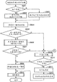
Fig. 8 is the process flow diagram of the AF scanning that is used for the last operation judges of reference of step S806 among Fig. 6.At step S1101, sweep limit is set to the first scope around the current location of focusing lens 104.Here, because it is roughly identical with last shooting scene to judge scene, thereby the first sweep limit is close limit.At step S1102, focusing lens 104 is moved to the scanning starting position.At step S1103, A/D converter section 109 will convert digital signal to from the simulation drawing picture signal that imaging apparatus 108 reads, image processing part 110 extracts the radio-frequency component of luminance signal from this digital signal, and by CPU 115 this radio-frequency component is stored as focus evaluated value.At step S1104, CPU 115 obtains the current location of focusing lens 104, and stores the data of this position.
At step S1105, CPU 115 judges the state (ON/OFF) that is used to indicate the SW1 that carries out the shooting preparation.When this state is ON, finish and work as pre-treatment, and step enters the step S212 among Fig. 2.When this state was OFF, step entered step S1106.At step S1106, carry out scene change and judge.At step S1107, CPU115 checks whether the current location of focusing lens 104 is consistent with scan end position.When these two positions were consistent with each other, step entered step S1108.If inconsistent, then step enters step S1109.At step S1108, carry out following main subject region decision (referring to Fig. 9).At step S1109, AF handling part 105 moves specified quantitative with focusing lens 104 to end of scan direction, and then, step is back to step S1103.
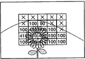
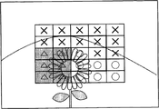
Fig. 9 is the process flow diagram of the main subject region decision of step S1108 among Fig. 8 and the step S1411 among following Figure 11.In main subject region decision, judged whether to determine the main subject zone in the plane of delineation.Figure 10 A~10C illustrates the example of the main subject region decision among Fig. 9.In this example, the size of AF frame is arranged to 10% of the plane of delineation, N=5, sweep limit is set to scope 0~500, and the certain depth scope be set to ± 10.Here, the numeral of sweep limit and certain depth scope is the numeral of the position of expression focusing lens 104.These numerals are corresponding to the umber of pulse of the stepping motor (not shown) of the driving motor that is used as focusing lens 104, and their value is along with focusing lens 104 increases near wide-angle side.
At step S1201, the focusing that each set AF frame carries out among above-mentioned Fig. 4 is judged.For example, in each AF frame, suppose that focusing on judged result is the result shown in Figure 10 A.At step S1202, calculate and store the peak (PeakPos) of the focus evaluated value in each AF frame.For example, for each AF frame, suppose that peak result of calculation is the result shown in Figure 10 B.At step S1203, the quantity that checks the AF frame is one (1) whether.When being provided with single AF frame, step enters step S1214.If not being provided with single AF frame, then step enters step S1204.
At step S1204, begin the PeakPos of the AF frame central M * M frame is sorted from wide-angle side.Represent the number that sorts with S.In the following description, suppose M=3.Among Figure 10 A~10C take the individual frame in 9 (3 * 3) that heavy line centers on as central M * M frame.Here, can not calculate in the focusing of step S1201 is judged be judged as *-peak of the AF frame judged, thereby get rid of this class AF frame from the AF frame that will sort.For example, in the situation of Figure 10 B, will be expressed as 410,400,400,400,100,100,100 and 90 from the ranking results that wide-angle side begins, and ordering number S is S=8.
At step S1205, be set to one (1) for the peak that is illustrated in M * M the frame that step S1202 calculates with respect to the counting P of the order of wide-angle side.At step S1206, P PeakPos is set to PeakPosP according to clooating sequence.For example, in the situation of Figure 10 B, when P=1, PeakPosP=410.At step S1207, in central M * M AF frame, have zero-judgement and the piece in the certain depth scope that the frame from PeakPosP begins in the detection AF frame, and storage consists of quantity and the position of the AF frame of this piece.Here, in this piece, for example, the AF frame that satisfies condition adjoins each other in the horizontal direction with on the vertical direction.Exist in a plurality of situation, in them is selected in the position that can consider the quantity of AF frame and each piece.
At step S1208, in central N * N AF frame, have zero-judgement and the piece in the certain depth scope that the frame from PeakPosP begins in the detection AF frame, so that in this piece, comprise central M * M at least one frame in the AF frame.Then, storage consists of quantity and the position of the AF frame of this piece.For example, in the situation of the judged result shown in Figure 10 A and 10B, detect the piece that comprises grey box shown in Figure 10 C.
At step S1209, check whether the piece that detects at step S1207 or S1208 comprises central frame.When this piece comprised central frame, step entered step S1215.If do not comprise, then step enters step S1210.At step S1210, check whether the piece that detects at step S1207 or S1208 comprises the frame of at least specific quantity in M * M the frame.When this piece comprised the frame of at least specific quantity in M * M the frame, step entered step S1215.Otherwise step enters step S1211.At step S1211, check at the piece that step S1207 or S1208 detect whether comprise at least one frame in central M * M frame and the frame of at least specific quantity in N * N frame.When this piece comprised the frame of at least one frame in central M * M frame and at least specific quantity in N * N frame, step entered step S1215.Otherwise step enters step S1212.At step S1212, will count P and add one (1).At step S1213, check that whether counting P is greater than ordering number S.When counting P greater than ordering number S, step enters step S1217.If be not more than, then step is back to step S1206.
At step S1214, the focusing judged result that checks step S1201 whether zero-judge.When this result was zero-judgement, step entered step S1215.If not, then step enters step S1217.At step S1215, go out affirmative determination to main subject zone is really customized.At step S1216, the AF frame that consists of this piece is judged as main subject zone and selects these AF frames, and finish current judgement and process.Only comprise at set like this AF frame in the situation of (1 a) frame, select this frame.At step S1217, judge and can not determine main subject zone, and finish current judgement and process.
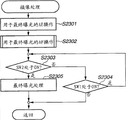
Figure 11 is the process flow diagram of the regional AF scanning of step S809 among Fig. 6.But the zone refers to by cutting apart each scope in the formed a plurality of scopes of focusing distance scope.
At step S1401, focusing lens 104 is moved to the scanning starting position.Here, for example, the scanning starting position is the position at end place of dolly-out,ing dolly-back.At step S1402, A/D converter section 109 will convert digital signal to from the simulation drawing picture signal that imaging apparatus 108 reads, image processing part 110 is from the radio-frequency component of this digital signal extraction luminance signal, and CPU 115 stores this radio-frequency component as focus evaluated value.At step S1403, CPU 115 obtains the current location of focusing lens 104, and stores the data of this position.
At step S1404, CPU 115 judges the state (ON/OFF) that is used to indicate the SW1 that carries out the shooting preparation.When this state is ON, finish and work as pre-treatment, and step enters the step S212 among Fig. 2.When this state was OFF, step entered step S1405.At step S1405, carry out scene change and judge.At step S1406, CPU115 checks whether the current location of focusing lens 104 is consistent with the boundary position in the zone that sets in advance.When these two positions were consistent with each other, step entered step S1407.If inconsistent, then step enters step S1409.At step S1407, carry out area update according to following process and judge (referring to Figure 12).Here, area update refers to scan this new region after the scanning zone adjacent with new region.
At step S1408, check based on the judged result of step S1407 whether determine to carry out area update.When determining to carry out area update, step enters step S1409.If determine not carry out area update, then step enters step S1411.At step S1409, CPU 115 checks whether the current location of focusing lens 104 is consistent with scan end position.When these two positions were consistent with each other, step entered step S1411.If inconsistent, then step enters step S1410.At step S1410, focusing lens 104 is moved specified quantitative to end of scan direction, then, step is back to step S1402.At step S1411, carry out the main subject region decision among above-mentioned Fig. 9.
Figure 12 is the process flow diagram that the area update of step S1407 among Figure 11 is judged.In area update is judged, judge that there is main subject in possibility on the forward position of direction of scanning.That is to say, judge whether to continue AF scanning.Figure 13 A and Figure 13 B illustrate the example of the area update judgement of Figure 12.In this example, the size of AF frame is arranged to 10% of the plane of delineation, N=5 and M=3.
At step S1501, each set AF frame is carried out the focusing of above-mentioned Fig. 4 and judge.For example, suppose the focusing judged result that in each AF frame, obtains as shown in FIG. 13A.At step S1502, check the scanning whether carry out to the last till the zone.During scanning till carrying out to the last a zone, step enters step S1512.If not, then step enters step S1503.At step S1503, check whether there is zero-decision block.When having zero-decision block, step enters step S1504.If there is no, then step enters step S1511.
At step S1504, what check central frame judges whether it is △-judgement.When the judgement of central frame was △-judgement, step entered step S1511.If not, then step enters step S1505.At step S1505, check in central M * M frame, whether there is at least piece of the △-decision block of specific quantity.When having this piece, step enters step S1511.If there is no this piece, then step enters step S1506.In the example of Figure 13 A and Figure 13 B, this specific quantity is set to two (2).At step S1506, check the piece whether exist the △-decision block that comprises in N * N the frame △-decision block of specific quantity at least and this specific quantity to comprise at least one frame in central M * M frame.When having this class piece, step enters step S1511.If there is no, then step enters step S1507.In the example of Figure 13 A and Figure 13 B, this specific quantity is set to four (4).At step S1507, check whether to exist to comprise in central M * M frame at least piece of zero-decision block of specific quantity.When having this class piece, step enters step S1512.If there is no, then step enters step S1508.In the example of Figure 13 A and Figure 13 B, this specific quantity is five (5).
At step S1508, whether check central frame *-decision block.When central frame be *-during decision block, step enters step S1511.If not, then step enters step S1509.At step S1509, check whether exist comprise in central M * M frame the △-decision block of specific quantity at least or *-piece of decision block.When having this class piece, step enters step S1511.If there is no, then step enters step S1510.In the example of Figure 13 A and Figure 13 B, this specific quantity is set to two (2).At step S1510, check whether exist comprise in N * N the frame △-decision block of specific quantity at least or *-△-decision block of decision block and this specific quantity or *-decision block comprises the piece of at least one frame in central M * M frame.When having this class piece, step enters step S1511.If there is no, then step enters step S1512.In the example of Figure 13 A and 13B, this specific quantity is four (4).At step S1511, judge and to carry out area update, and finish current judgement and process.At step S1512, judge and do not carry out area update, and finish current judgement and process.
For example, in the situation of N=5 and M=3, this piece be among Figure 13 B with the zone shown in the grey, and judge and will carry out area update.
Figure 14 is the process flow diagram that the focusing of step S813 among Fig. 6 drives.At step S2001, check whether identified main subject zone.When having determined main subject zone, step enters step S2002.If no, then step enters step S2003.At step S2002, focus is urged to wide-angle side position in the selected AF frame, and finishes and work as pre-treatment.At step S2003, check in central M * M frame, whether have zero-decision block.When having zero-decision block, step enters step S2004.If there is no, then step enters step S2005.At step S2004, focus is urged to the wide-angle side position of zero-decision block in central M * M frame, and finishes and work as pre-treatment.At step S2005, focusing lens is urged to pre-stored position (point of fixity), and finishes and work as pre-treatment.Here, for example, point of fixity be subject have a high distance and position of possibility.
Figure 15 is the process flow diagram of the continuous AF of step S209 among Fig. 2.At step S2101, the focus level judgement symbol is set to TRUE.At step S2102, in each set AF frame, obtain focus evaluated value.
At step S2103, check whether the quantity of set AF frame is one (1).When the AF frame was one, step entered step S2105.If not, then step enters step S2104.At step S2104, the evaluation of estimate that will calculate by the focus evaluated value of using the AF frame of selecting as main subject zone is re-set as employed focus evaluated value after step S2105.Thereby even the shooting scene change, and the main subject area change in the plane of delineation also can calculate the focus evaluated value in the main subject zone in the plane of delineation.
At step S2105, calculate focus level based on this focus evaluated value.In this embodiment, based on this focus evaluated value, focus level is divided into height, low three degree of neutralization.At step S2106, CPU 115 judges the state (ON/OFF) that is used to indicate the SW1 that carries out the shooting preparation.When this state is ON, finish and work as pre-treatment, and step enters the step S213 among Fig. 2.When this state was OFF, step entered step S2107.At step S2107, carry out scene change and judge.
At step S2108, check that peak value detects whether sign is TRUE.When being TRUE, step enters step S2125.When being FALSE, step enters step S2109.At step S2109, obtain the current location of focusing lens 104.At step S2110, will add one (1) for the counting that obtains that obtaining of the current location of focusing evaluation of estimate and focusing lens 104 counted.In initialization operation, suppose that it is zero (0) that this counting is set in advance.At step S2111, check whether the value of obtaining counting is one (1).When this value was 1, step entered step S2114.If this value is not 1, then step enters step S2112.
At step S2112, check that whether the current focus evaluation of estimate is greater than last focus evaluated value.When the former during greater than the latter, step enters step S2113.If not, then step enters step S2120.At step S2113, the increment counting is added one (1).At step S2114, the current focus evaluation of estimate is set to the maximal value of focus evaluated value, and it is stored in the operand store (not shown) that is built among the CPU 115.At step S2115, the current location of focusing lens 104 is set to the position corresponding with the peak value of focus evaluated value, and it is stored in the operand store that is built among the CPU 115.At step S2116, the current focus evaluation of estimate is set to last focus evaluated value, and it is stored in the operand store that is built among the CPU 115.At step S2117, whether the current location that checks focusing lens 104 is in the end of focusing lens moving range.When current location during in the end, step enters step S2118.If not, then step enters step S2119.At step S2118, the moving direction of counter-rotating focusing lens 104.At step S2119, focusing lens 104 is moved scheduled volume.
At step S2120, check that whether " (maximal value of focus evaluated value)-(current focus evaluation of estimate) " be greater than particular value.When this differed from greater than particular value, step entered step S2121.If not, then step enters step S2116.Here, if should be poor greater than particular value, when namely the current focus evaluation of estimate is than the little particular value of maximal value, maximal value be worked as the value corresponding with the focus peak.At step S2121, check that whether the increment counting is greater than zero (0).When increment counting greater than 0 the time, step enters step S2122.If not, then step enters step S2116.At step S2122, focusing lens 104 is moved to the peak corresponding with the maximal value of the focus evaluated value of storing at step S2115.At step S2123, be TRUE with the peak value detection flag.At step S2124, obtain counting and be set to zero (0).
At step S2125, check whether the current focus evaluation of estimate has changed more than the specific ratios with respect to the maximal value of focus evaluated value.When the current focus evaluation of estimate has changed specific ratios when above, step enters step S2127.If the current focus evaluation of estimate does not change more than the specific ratios, then step enters step S2126.At step S2126, keep the invariant position of focusing lens 104.At step S2127, become the position of peaked focusing lens in order again to seek focus evaluated value, be FALSE with the peak value detection flag, and the maximal value of the focus evaluated value that resets and peak.At step S2128, the increment that resets counting.
As mentioned above, in AF operates continuously, drive focusing lens so that main subject remains in focusing state.
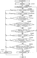
Figure 16 is the process flow diagram that the shooting of step S213 among Fig. 2 is processed.At step S2301, AE handling part 103 carries out processing for the AE of final exposure.At step S2302, carry out operating (referring to Figure 17) for the AF of final exposure according to following process.At step S2303, CPU 115 judges the state (ON/OFF) of shooting interrupteur SW 2 (122).When this state was ON, step entered step S2305.When this state was OFF, step entered step S2304.At step S2304, judge the state (ON/OFF) that is used to indicate the SW 1 that carries out the shooting preparation.When this state was ON, step entered step S2303.When this state is OFF, finishes and work as pre-treatment.At step S2305, carry out final exposure-processed, and finish and work as pre-treatment.Followingly carry out final exposure-processed.After the exposure of imaging apparatus 108, read in the data of accumulating in the imaging apparatus 108.A/D converter section 109 will become digital signal from the analog signal conversion that imaging apparatus 108 reads.110 pairs of digital signals from 109 outputs of A/D converter section of image processing part are carried out various images and are processed.Under the control of CPU 115, according to the image after the such processing of the format compressions such as JPEG.Then, the data after will compressing under the control of CPU 115 provide to recording image section 114 and are recorded in the recording image section 114.
Figure 17 is the process flow diagram of the AF operation that is used for final exposure of step S 2302 among Figure 16.At step S2401, carry out the AF frame setting for final exposure.Arrange at the AF frame that is used for final exposure, the frame with specific size can be set in middle section, a plurality of N * N frame perhaps can be set.At step S2402, check whether main object mark will is TRUE.When this was masked as TRUE, step entered step S2403.If not, then step enters step S2409.At step S2403, check whether the focus level that calculates at the step S2105 of Figure 15 is high.When focus level when being high, step enters step S2404.If not, then step enters step S2405.
At step S2404, sweep limit is arranged in current location first scope (1) on every side of focusing lens 104.Here, judge main subject and be in focusing state owing to continuous AF operation be similar to, i.e. the close focusing position corresponding with the peak value of focus evaluated value in the position of focusing lens, and narrow sweep limit is set.At step S2405, check in whether focus level that step S2105 calculates is.When focus level when being middle, step enters step S2406.If not, then step enters step S2407.At step S2406, sweep limit is arranged in current location second scope (2) on every side of focusing lens 104.Here, although judge focusing lens owing to the AF operation is near focusing position continuously, focus level is not quite high, and sweep limit is arranged to the close limit wider than the first sweep limit.At step S2407, check whether the current location of focusing lens 104 is in microspur (macro) zone.When current location was in the microspur zone, step entered step S2408.If not, then step enters step S2409.At step S2408, sweep limit is arranged to the 3rd scope (3) pre-stored in the microspur zone.At step S2409, but sweep limit is arranged to pre-stored the 4th scope (4) as whole focus sensing range.
At step S2501, focusing lens 104 is moved to the scanning starting position.Suppose that the scanning starting position is the end position in the set sweep limit of step S2404, S2406, S2408 or S2409.At step S2502, A/D converter section 109 will convert digital signal to from the simulation drawing picture signal that imaging apparatus 108 reads, image processing part 110 is from the radio-frequency component of this digital signal extraction luminance signal, and CPU 115 stores this radio-frequency component as focus evaluated value.At step S2503, CPU 115 obtains the current location of focusing lens 104, and stores the data of this position.At step S2504, CPU 115 checks whether the current location of focusing lens 104 is consistent with scan end position.When this two position consistency, step enters step S2506.If inconsistent, then step enters step S2505.At step S2505, focusing lens 104 is moved specified quantitative to end of scan direction, then step is back to step S2502.At step S2506, according to the focus evaluated value of storing at step S2502 and lens position thereof, calculate the peak of focus evaluated value.When calculating the peak of focus evaluated value, if be provided with a plurality of AF frames, then can based on the peak on the wide-angle side in the determined main subject of the main subject region decision zone of passing through Fig. 9, carry out this calculating.Perhaps, can calculate peak by other determination methods.Then, at step S2411, focusing lens 104 is moved to the peak that calculates at step S2506.
As mentioned above, in the present embodiment, owing to before the indication that is used for the shooting beamhouse operation, determine main subject zone, and main subject regional sustained is focused on, thereby after the indication that is used for the shooting beamhouse operation, can focus on rapidly on the main subject.In addition, the result based on facial testing result and last AF scanning can limit for the AF sweep limit of determining main subject zone.Therefore, can improve picture appearance and efficient when determining main subject zone before the shooting beamhouse operation.
Figure 18 is the process flow diagram of main subject region decision of the step S1411 of the step S1108 of Fig. 8 among the second embodiment and Figure 11.In a second embodiment, compare with the process flow diagram of Fig. 9 of the first embodiment, the part of step S2709 and S2710 is different.In addition, in these steps, judged whether to determine the main subject zone in the plane of delineation.Figure 10 A and 10B also illustrate the example of the main subject region decision among Figure 18.
At step S2701, each set AF frame is carried out the focusing of above-mentioned Fig. 4 and judge.In addition,, in each AF frame, suppose that focusing on judged result is the result shown in Figure 10 A here.At step S2702, calculate and store the peak of the focus evaluated value in each AF frame.For example, in each AF frame, suppose that peak result of calculation is the result shown in Figure 10 B.At step S2703, the quantity that checks set AF frame is one (1) whether.When being provided with single AF frame, step enters step S2716.If not being provided with single AF frame, then step enters step S2704.
At step S2704, begin the PeakPos of the AF frame central M * M frame is sorted from wide-angle side.Represent the number that sorts with S.In addition, here, M=3.The individual frame in 9 (3 * 3) that surrounds take heavy line among Figure 10 A~10C is as central M * M frame.Here, can not calculate the peak that in the focusing of step S2701 is judged, is judged as the AF frame of x-judgement, thereby get rid of this class AF frame from the AF frame that will sort.In the situation of Figure 10 B, will be expressed as 410,400,400,400,100,100,100 and 90 from the ranking results that wide-angle side begins, and ordering number S is S=8.
At step S2705, be set to one (1) be used to being illustrated in peak that step S2702 the calculates counting P with respect to the order of wide-angle side.At step S2706, be set to PeakPosP according to P PeakPos of clooating sequence.In the situation of Figure 10 B, when P=1, PeakPosP=410.At step S2707, in central M * M AF frame, have zero-judgement and the piece in the certain depth scope that the frame from PeakPosP begins in the detection AF frame, and storage consists of quantity and the position of the AF frame of this piece.At step S2708, in central N * N AF frame, detect have zero in the AF frame-judge and in the certain depth scope that the frame from PeakPosP begins and comprise the piece of central M * M at least one frame the AF frame and quantity and the position of the AF frame of this piece of storage formation.In the situation of the judged result shown in Figure 10 A and Figure 10 B, detect the piece that comprises among Figure 10 C with the frame shown in the grey.
At step S2709, check main subject region decision when pre-treatment whether the step S806 among Fig. 6 be used for AF scanning with reference to last operation judges the time processing.If so, then step enters step S2710.If not, then step enters step S2711.
At step S2710, check whether the piece that detects at step S2707 or S2708 comprises the frame of at least specific quantity in last subject zone.When this piece comprised the frame of at least specific quantity in last subject zone, step entered step S2717.Otherwise step enters step S2711.
At step S2711, check whether the piece that detects at step S2707 or S2708 comprises central frame.When this piece comprised central frame, step entered step S2717.If this piece does not comprise central frame, then step enters step S2712.At step S2712, check whether the piece that detects at step S2707 or S2708 comprises in central M * M frame at least frame of specific quantity.When this piece comprised in central M * M frame at least the frame of specific quantity, step entered step S2717.Otherwise step enters step S2713.At step S2713, check at the piece that step S2707 or S2708 detect whether comprise at least one frame in central M * M frame and the central N * N frame at least frame of specific quantity.When this piece comprised at least one frame in central M * M frame and the central N * N frame at least the frame of specific quantity, step entered step S2717.Otherwise step enters step S2714.At step S2714, will count P and add one (1).At step S2715, check that whether counting P is greater than ordering number S.When counting P greater than ordering number S, step enters step S2719.If be not more than, then step is back to step S2706.
At step S2716, the focusing judged result that checks step S2701 whether zero-judge.When this result was zero-judgement, step entered step S2717.If not, then step enters step S2719.At step S2717, go out affirmative determination to main subject zone is really customized.At step S2718, the AF frame that consists of this piece is judged as main subject zone and selects these AF frames, and finish current judgement and process.Only comprise at set like this AF frame in the situation of (1 a) frame, select this frame.At step S2719, judge and can not determine main subject zone, and finish current judgement and process.
As mentioned above, in the present embodiment, when determining main subject zone, the preferential frame of selecting to comprise the frame position in the last main subject zone.Therefore, can more effective and accurately realize determining of main subject zone.
Except illustrating in addition in this article, all be known with the various assemblies shown in frame or the piece form in these accompanying drawings, and their inner structure and operation are for realizing or use the present invention or not being crucial for the explanation of best mode of the present invention.
Although with reference to exemplary embodiments the present invention has been described, should be appreciated that, the invention is not restricted to disclosed exemplary embodiments.The scope of appended claims meets the widest explanation, to comprise all this class modification and equivalent structure and functions.
The application requires the right of priority of the 2009-034113 Japanese patent application of submission on February 17th, 2009, and its full content is contained in this by reference.
Claims (8)
1. focus adjusting apparatus comprises:
Receiving element is used for receiving the indication that is used for focal adjustments;
Image unit is used for making a video recording with output image data by the subject image of focusing lens input;
Setting unit is used for arranging the focus detection zone; And
The focal adjustments unit is used for detecting the focus signal of the focus state of focusing lens described in the described focus detection of the expression zone in mobile described focusing lens, in preset range, regulating the position of described focusing lens based on described focus signal,
Wherein, described focal adjustments unit controls the first operation and the second operation, described the first operation is for detecting the subject zone of described focus signal to determine to focus on before receiving described indication, described the second operation detects described focus signal to carry out the focal adjustments of described focusing lens for the information based on the determined subject zone that will focus on when receiving described indication; And
Described focal adjustments unit judged whether to detect face by the output signal based on described image unit before described the first operation, judge whether to predict the subject that will focus on, and when not detecting face, in described the first operation, described focal adjustments unit the first moving range is set to the moving range of described focusing lens, and when detecting face, described focal adjustments unit arranges second moving range narrower than described the first moving range.
2. focus adjusting apparatus according to claim 1 is characterized in that, based on by the described facial information that obtains that detects, determines described the second moving range.
3. focus adjusting apparatus comprises:
Receiving element is used for receiving the indication that is used for focal adjustments;
Image unit is used for making a video recording with output image data by the subject image of focusing lens input;
Setting unit is used for arranging the focus detection zone; And
The focal adjustments unit is used for detecting the focus signal of the focus state of focusing lens described in the described focus detection of the expression zone in mobile described focusing lens, in preset range, regulating the position of described focusing lens based on described focus signal,
Wherein, described focal adjustments unit controls the first operation and the second operation, described the first operation is for detecting the subject zone of described focus signal to determine to focus on before receiving described indication, described the second operation detects described focus signal to carry out the focal adjustments of described focusing lens for the information based on the determined subject zone that will focus on when receiving described indication; And
Described focal adjustments unit shooting scene by according to last AF operation time the before described the first operation judges that whether current shooting scene changes, and judges whether to predict the subject that will focus on; And when the shooting scene changes, in described the first operation, described focal adjustments unit the first moving range is set to the moving range of described focusing lens, and when the shooting scene did not change, described focal adjustments unit arranged second moving range narrower than described the first moving range.
4. focus adjusting apparatus according to claim 3 is characterized in that, based on the current location of described focusing lens, determines described the second moving range.
5. focus adjusting method that is used for the control focus adjusting apparatus, described focus adjusting apparatus comprises image unit, described image unit is used for making a video recording with output image data by the image of focusing lens input, and described focus adjusting method may further comprise the steps:
Carry out an AF scan operation, a described AF scan operation is used for carrying out when moving described focusing lens before the shooting beamhouse operation and the position of described focusing lens obtains described image unit explicitly in the scan operation of the output signal in set focus detection zone; And determine that the subject that will focus on is regional;
Be different from the 2nd AF scan operation of a described AF scan operation, described the 2nd AF scan operation is for the scan operation of carrying out focusing when described shooting beamhouse operation and operating; And
Carrying out judging whether to detect face by the output signal based on described image unit before the described AF scan operation, judge whether to predict the subject that will focus on;
When not detecting face, in a described AF scan operation, the first moving range is set to the moving range of described focusing lens; And
When detecting face, second moving range narrower than described the first moving range is set.
6. focus adjusting method according to claim 5 is characterized in that, also comprises: based on by the described facial information that obtains that detects, determine described the second moving range.
7. focus adjusting method that is used for the control focus adjusting apparatus, described focus adjusting apparatus comprises image unit, described image unit is used for making a video recording with output image data by the image of focusing lens input, and described focus adjusting method may further comprise the steps:
Carry out an AF scan operation, a described AF scan operation is used for carrying out when moving described focusing lens before the shooting beamhouse operation and the position of described focusing lens obtains described image unit explicitly in the scan operation of the output signal in set focus detection zone; And determine that the subject that will focus on is regional;
Be different from the 2nd AF scan operation of a described AF scan operation, described the 2nd AF scan operation is for the scan operation of carrying out focusing when described shooting beamhouse operation and operating; And
Shooting scene before carrying out a described AF scan operation by according to last AF operation the time judges that whether current shooting scene changes, and judges whether to predict the subject that will focus on;
When the shooting scene changed, in a described AF scan operation, the first moving range was set to the moving range of described focusing lens; And
When the shooting scene does not change, second moving range narrower than described the first moving range is set.
8. focus adjusting method according to claim 7 is characterized in that, also comprises: based on the current location of described focusing lens, determine described the second moving range.
Applications Claiming Priority (2)
| Application Number | Priority Date | Filing Date | Title |
|---|---|---|---|
| JP2009034113A JP5300520B2 (en) | 2009-02-17 | 2009-02-17 | Focus adjustment device and focus adjustment method |
| JP2009-034113 | 2009-02-17 |
Publications (2)
| Publication Number | Publication Date |
|---|---|
| CN101806948A CN101806948A (en) | 2010-08-18 |
| CN101806948B true CN101806948B (en) | 2013-02-13 |
Family
ID=42559984
Family Applications (1)
| Application Number | Title | Priority Date | Filing Date |
|---|---|---|---|
| CN2010101170618A Active CN101806948B (en) | 2009-02-17 | 2010-02-20 | Focus adjusting apparatus and focus adjusting method |
Country Status (3)
| Country | Link |
|---|---|
| US (1) | US7957633B2 (en) |
| JP (1) | JP5300520B2 (en) |
| CN (1) | CN101806948B (en) |
Families Citing this family (10)
| Publication number | Priority date | Publication date | Assignee | Title |
|---|---|---|---|---|
| JP5217600B2 (en) * | 2008-04-22 | 2013-06-19 | ソニー株式会社 | Imaging device |
| TWI383673B (en) * | 2009-09-01 | 2013-01-21 | Quanta Comp Inc | Method and device for adjusting weighting values in light metering |
| US9049364B2 (en) * | 2012-02-13 | 2015-06-02 | Htc Corporation | Focus adjusting method and image capture device thereof |
| JP5949591B2 (en) * | 2013-02-13 | 2016-07-06 | ソニー株式会社 | Imaging apparatus, control method, and program |
| JP6539015B2 (en) * | 2013-12-05 | 2019-07-03 | キヤノン株式会社 | Image pickup apparatus and control method thereof |
| TWI524108B (en) | 2014-04-24 | 2016-03-01 | 瑞昱半導體股份有限公司 | Passive auto-focus device and method |
| JP6618255B2 (en) | 2014-12-24 | 2019-12-11 | キヤノン株式会社 | Zoom control device, imaging device, control method for zoom control device, control program for zoom control device, and storage medium |
| JP6474693B2 (en) * | 2015-06-19 | 2019-02-27 | オリンパス株式会社 | Focus detection apparatus, focus detection method, and recording medium |
| TWI585394B (en) * | 2015-12-09 | 2017-06-01 | 由田新技股份有限公司 | Automatic focusing system |
| CN110381261B (en) * | 2019-08-29 | 2020-11-03 | 重庆紫光华山智安科技有限公司 | Focusing method, focusing device, computer-readable storage medium and electronic equipment |
Citations (4)
| Publication number | Priority date | Publication date | Assignee | Title |
|---|---|---|---|---|
| US5144357A (en) * | 1987-11-06 | 1992-09-01 | Minolta Camera Kabushiki Kaisha | Automatic focus detecting means |
| CN1924689A (en) * | 2005-08-31 | 2007-03-07 | 株式会社尼康 | Autofocus apparatus |
| CN101241222A (en) * | 2007-02-08 | 2008-08-13 | 佳能株式会社 | Focus adjusting device, image pickup apparatus, and focus adjustment method |
| CN101309366A (en) * | 2007-05-15 | 2008-11-19 | 佳能株式会社 | Image pickup apparatus and control method therefor |
Family Cites Families (3)
| Publication number | Priority date | Publication date | Assignee | Title |
|---|---|---|---|---|
| JP4106485B2 (en) | 2002-03-29 | 2008-06-25 | 株式会社ニコン | camera |
| JP4674471B2 (en) * | 2005-01-18 | 2011-04-20 | 株式会社ニコン | Digital camera |
| JP4429328B2 (en) * | 2007-02-09 | 2010-03-10 | キヤノン株式会社 | Automatic focusing device, control method therefor, and imaging device |
-
2009
- 2009-02-17 JP JP2009034113A patent/JP5300520B2/en active Active
-
2010
- 2010-02-12 US US12/705,327 patent/US7957633B2/en not_active Expired - Fee Related
- 2010-02-20 CN CN2010101170618A patent/CN101806948B/en active Active
Patent Citations (4)
| Publication number | Priority date | Publication date | Assignee | Title |
|---|---|---|---|---|
| US5144357A (en) * | 1987-11-06 | 1992-09-01 | Minolta Camera Kabushiki Kaisha | Automatic focus detecting means |
| CN1924689A (en) * | 2005-08-31 | 2007-03-07 | 株式会社尼康 | Autofocus apparatus |
| CN101241222A (en) * | 2007-02-08 | 2008-08-13 | 佳能株式会社 | Focus adjusting device, image pickup apparatus, and focus adjustment method |
| CN101309366A (en) * | 2007-05-15 | 2008-11-19 | 佳能株式会社 | Image pickup apparatus and control method therefor |
Also Published As
| Publication number | Publication date |
|---|---|
| JP2010191082A (en) | 2010-09-02 |
| US20100209093A1 (en) | 2010-08-19 |
| US7957633B2 (en) | 2011-06-07 |
| CN101806948A (en) | 2010-08-18 |
| JP5300520B2 (en) | 2013-09-25 |
Similar Documents
| Publication | Publication Date | Title |
|---|---|---|
| CN101806948B (en) | Focus adjusting apparatus and focus adjusting method | |
| CN101806950B (en) | Focus adjusting apparatus and focus adjusting method | |
| CN101808197B (en) | Focus adjustment apparatus and focus adjustment method | |
| JP5288015B2 (en) | Image tracking device, image tracking method, and camera | |
| CN101013190B (en) | Focusing device, image pickup apparatus, and control method | |
| CN101806949B (en) | Focus adjusting apparatus and focus adjusting method | |
| US8189056B2 (en) | Image capturing apparatus, angle-of-view adjusting method and recording medium | |
| JP5406552B2 (en) | Focus adjustment device and focus adjustment method | |
| CN104754213A (en) | Image capturing apparatus and control method thereof | |
| JP5339955B2 (en) | Focus adjustment device and focus adjustment method | |
| JP5406553B2 (en) | Focus adjustment device and focus adjustment method | |
| JP5300521B2 (en) | Focus adjustment device and focus adjustment method | |
| JP7289714B2 (en) | FOCUS ADJUSTMENT DEVICE, IMAGING DEVICE, FOCUS ADJUSTMENT METHOD, AND PROGRAM | |
| JP5855054B2 (en) | Focus adjustment device and focus adjustment method | |
| CN100594418C (en) | Image picking device, its focusing method and image contrast value determination method | |
| WO2005033763A1 (en) | Imaging lens position control device | |
| JP7191680B2 (en) | Image processing device and imaging device | |
| JP6590496B2 (en) | Imaging device, control method thereof, and program | |
| US20230076475A1 (en) | Electronic apparatus and control method | |
| JP2011043633A (en) | Focus adjustment device and focus adjustment method | |
| JP2011043632A (en) | Focus-adjusting device and focus-adjusting method |
Legal Events
| Date | Code | Title | Description |
|---|---|---|---|
| C06 | Publication | ||
| PB01 | Publication | ||
| C10 | Entry into substantive examination | ||
| SE01 | Entry into force of request for substantive examination | ||
| C14 | Grant of patent or utility model | ||
| GR01 | Patent grant |