CN101797842B - Ink jet print head - Google Patents
Ink jet print head Download PDFInfo
- Publication number
- CN101797842B CN101797842B CN201010112069.5A CN201010112069A CN101797842B CN 101797842 B CN101797842 B CN 101797842B CN 201010112069 A CN201010112069 A CN 201010112069A CN 101797842 B CN101797842 B CN 101797842B
- Authority
- CN
- China
- Prior art keywords
- heat
- applies
- supply port
- jet
- orientation
- Prior art date
- Legal status (The legal status is an assumption and is not a legal conclusion. Google has not performed a legal analysis and makes no representation as to the accuracy of the status listed.)
- Active
Links
Images


Classifications
-
- B—PERFORMING OPERATIONS; TRANSPORTING
- B41—PRINTING; LINING MACHINES; TYPEWRITERS; STAMPS
- B41J—TYPEWRITERS; SELECTIVE PRINTING MECHANISMS, i.e. MECHANISMS PRINTING OTHERWISE THAN FROM A FORME; CORRECTION OF TYPOGRAPHICAL ERRORS
- B41J2/00—Typewriters or selective printing mechanisms characterised by the printing or marking process for which they are designed
- B41J2/005—Typewriters or selective printing mechanisms characterised by the printing or marking process for which they are designed characterised by bringing liquid or particles selectively into contact with a printing material
- B41J2/01—Ink jet
- B41J2/135—Nozzles
- B41J2/14—Structure thereof only for on-demand ink jet heads
- B41J2/14427—Structure of ink jet print heads with thermal bend detached actuators
-
- B—PERFORMING OPERATIONS; TRANSPORTING
- B41—PRINTING; LINING MACHINES; TYPEWRITERS; STAMPS
- B41J—TYPEWRITERS; SELECTIVE PRINTING MECHANISMS, i.e. MECHANISMS PRINTING OTHERWISE THAN FROM A FORME; CORRECTION OF TYPOGRAPHICAL ERRORS
- B41J2/00—Typewriters or selective printing mechanisms characterised by the printing or marking process for which they are designed
- B41J2/005—Typewriters or selective printing mechanisms characterised by the printing or marking process for which they are designed characterised by bringing liquid or particles selectively into contact with a printing material
- B41J2/01—Ink jet
- B41J2/135—Nozzles
- B41J2/14—Structure thereof only for on-demand ink jet heads
- B41J2/14016—Structure of bubble jet print heads
- B41J2/14032—Structure of the pressure chamber
- B41J2/1404—Geometrical characteristics
-
- B—PERFORMING OPERATIONS; TRANSPORTING
- B41—PRINTING; LINING MACHINES; TYPEWRITERS; STAMPS
- B41J—TYPEWRITERS; SELECTIVE PRINTING MECHANISMS, i.e. MECHANISMS PRINTING OTHERWISE THAN FROM A FORME; CORRECTION OF TYPOGRAPHICAL ERRORS
- B41J2/00—Typewriters or selective printing mechanisms characterised by the printing or marking process for which they are designed
- B41J2/005—Typewriters or selective printing mechanisms characterised by the printing or marking process for which they are designed characterised by bringing liquid or particles selectively into contact with a printing material
- B41J2/01—Ink jet
- B41J2/135—Nozzles
- B41J2/14—Structure thereof only for on-demand ink jet heads
- B41J2/14016—Structure of bubble jet print heads
- B41J2/14145—Structure of the manifold
-
- B—PERFORMING OPERATIONS; TRANSPORTING
- B41—PRINTING; LINING MACHINES; TYPEWRITERS; STAMPS
- B41J—TYPEWRITERS; SELECTIVE PRINTING MECHANISMS, i.e. MECHANISMS PRINTING OTHERWISE THAN FROM A FORME; CORRECTION OF TYPOGRAPHICAL ERRORS
- B41J2/00—Typewriters or selective printing mechanisms characterised by the printing or marking process for which they are designed
- B41J2/005—Typewriters or selective printing mechanisms characterised by the printing or marking process for which they are designed characterised by bringing liquid or particles selectively into contact with a printing material
- B41J2/01—Ink jet
- B41J2/135—Nozzles
- B41J2/14—Structure thereof only for on-demand ink jet heads
- B41J2002/14387—Front shooter
-
- B—PERFORMING OPERATIONS; TRANSPORTING
- B41—PRINTING; LINING MACHINES; TYPEWRITERS; STAMPS
- B41J—TYPEWRITERS; SELECTIVE PRINTING MECHANISMS, i.e. MECHANISMS PRINTING OTHERWISE THAN FROM A FORME; CORRECTION OF TYPOGRAPHICAL ERRORS
- B41J2/00—Typewriters or selective printing mechanisms characterised by the printing or marking process for which they are designed
- B41J2/005—Typewriters or selective printing mechanisms characterised by the printing or marking process for which they are designed characterised by bringing liquid or particles selectively into contact with a printing material
- B41J2/01—Ink jet
- B41J2/135—Nozzles
- B41J2/14—Structure thereof only for on-demand ink jet heads
- B41J2002/14403—Structure thereof only for on-demand ink jet heads including a filter
-
- B—PERFORMING OPERATIONS; TRANSPORTING
- B41—PRINTING; LINING MACHINES; TYPEWRITERS; STAMPS
- B41J—TYPEWRITERS; SELECTIVE PRINTING MECHANISMS, i.e. MECHANISMS PRINTING OTHERWISE THAN FROM A FORME; CORRECTION OF TYPOGRAPHICAL ERRORS
- B41J2/00—Typewriters or selective printing mechanisms characterised by the printing or marking process for which they are designed
- B41J2/005—Typewriters or selective printing mechanisms characterised by the printing or marking process for which they are designed characterised by bringing liquid or particles selectively into contact with a printing material
- B41J2/01—Ink jet
- B41J2/135—Nozzles
- B41J2/14—Structure thereof only for on-demand ink jet heads
- B41J2002/14467—Multiple feed channels per ink chamber
-
- B—PERFORMING OPERATIONS; TRANSPORTING
- B41—PRINTING; LINING MACHINES; TYPEWRITERS; STAMPS
- B41J—TYPEWRITERS; SELECTIVE PRINTING MECHANISMS, i.e. MECHANISMS PRINTING OTHERWISE THAN FROM A FORME; CORRECTION OF TYPOGRAPHICAL ERRORS
- B41J2202/00—Embodiments of or processes related to ink-jet or thermal heads
- B41J2202/01—Embodiments of or processes related to ink-jet heads
- B41J2202/11—Embodiments of or processes related to ink-jet heads characterised by specific geometrical characteristics
Landscapes
- Physics & Mathematics (AREA)
- Geometry (AREA)
- Particle Formation And Scattering Control In Inkjet Printers (AREA)
Abstract
An ink jet print head is provided which can improve throughput by increasing an ink ejection frequency and prevent crosstalk among a plurality of heat application portions, realizing a capability of printing high-quality images at high speed. An opening size of the supply ports in a direction perpendicular to the array direction of the heat application portions is made greater than the length in the direction of electrothermal conversion elements. The supply ports are arranged along the array direction so that they adjoin the heat application portions in the array direction.
Description
Technical field
The present invention relates to a kind of heat of electrothermal conversioning element of using and apply the ink jet-print head of the China ink of portion (or balancing gate pit) from the inkjet mouth ejection will be housed in heat.
Background technology
EP1078754 discloses a kind of ink jet-print head; This ink jet-print head has two ink supply ports that are used for a jet; And in this ink jet-print head, eject from jet through using the heat that produces by electrothermal conversioning element to be supplied to the China ink that heat applies portion via these ink supply ports.Ink supply port forms than sprays young to prevent that foreign matter from getting into heat and applying portion.
Can prevent that than spraying young ink supply port foreign matter from getting into heat and applying portion, but after ejecting ink, once more China ink supplied to heat when applying portion (also being called as " recharging "), increase black flow resistance via inkjet mouth.Therefore, can not increase black injection frequency, make and to improve handling capacity (throughput)
Summary of the invention
The present invention provides a kind of ink jet-print head; This ink jet-print head can increase black injection frequency to improve handling capacity; And a plurality of heat apply the influence of the pressure between the portion in the time of can reducing the China ink injection simultaneously, or reduce so-called crosstalking (crosstalk), thus can be with the flying print high quality image.
In one aspect of the invention; A kind of ink jet-print head is provided; It has a plurality of heat and applies portion and a plurality of supply port; Wherein, each heat applies the heat energy of portion through using electrothermal conversioning element and will be supplied to China ink that this heat applies portion from least one supply port and eject from the jet of correspondence, and the more than one heat portion of applying alternately arranges with supply port in a predetermined direction; At least one supply port perpendicular to the opening size on the direction of predetermined direction than electrothermal conversioning element big perpendicular to the length on the direction of predetermined direction.
Through the present invention, the opening size that applies on the vertical direction of the orientation of portion with heat that makes supply port is bigger than the length that applies on the vertical direction of the orientation of portion with heat of electrothermal conversioning element.Black flow resistance when this layout can reduce China ink recharged heat and apply portion, this then allow to increase black injection frequency, improved handling capacity.In addition; Orientation arrange openings size through applying portion along heat is by a plurality of supply ports that as above are provided with and apply in the orientation of portion in heat they and the heat portion of applying is adjacent to be provided with (being arranged on heat applies between the portion); The pressure that heat applies in the portion can be absorbed through supply port effectively, applies crosstalking between the portion to reduce a plurality of heat.This transfers to allow with the flying print high quality image.
From the explanation of following illustrative embodiment (with reference to accompanying drawing), it is obvious that further feature of the present invention will become.
Description of drawings
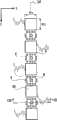
Fig. 1 is the plane of major part that the printhead of first embodiment of the present invention is shown;
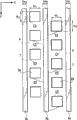
Fig. 2 is the enlarged drawing of major part of the nozzle rows of Fig. 1;
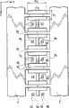
Fig. 3 is the cutaway view along the line III-III intercepting of Fig. 2;
Fig. 4 is the cutaway view along the line IV-IV intercepting of Fig. 2;
Fig. 5 is the enlarged drawing of major part of a nozzle rows of second embodiment of the present invention;
Fig. 6 is the cutaway view along the line VI-VI intercepting of Fig. 5;
Fig. 7 is the enlarged drawing of major part of a nozzle rows of the 3rd embodiment of the present invention;
Fig. 8 is the cutaway view along the line VIII-VIII intercepting of Fig. 7;
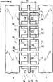
Fig. 9 A, Fig. 9 B and Fig. 9 C are the enlarged drawings of major part of the nozzle rows of the 4th embodiment of the present invention;
Figure 10 A and Figure 10 B are the enlarged drawings of major part of the nozzle rows of the 5th embodiment of the present invention;
Figure 11 A and Figure 11 B are the enlarged drawings of major part of the nozzle rows of the 6th embodiment of the present invention;
Figure 12 A and Figure 12 B are the enlarged drawings of major part of the nozzle rows of the 7th embodiment of the present invention;
Figure 13 is the approximate three-dimensional map that can use ink jet printing device of the present invention;
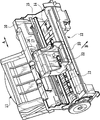
Figure 14 can be mounted to the box (headcartridge) of ink jet printing device of Figure 13 from the stereogram of beneath;
Figure 15 is the exploded perspective view that the box of Figure 13 is observed from the top.
The specific embodiment
Before embodiment of the present invention is elaborated, will the typical construction of the ink jet printing device that can use ink jet-print head of the present invention be described.
The typical construction of ink jet printing device
Figure 13 is the approximate three-dimensional map of frame for movement that can use the ink jet printing device of ink jet-print head of the present invention.Figure 14 is the approximate three-dimensional map that is used in the box in the ink jet printing device.Figure 15 will be mounted the approximate three-dimensional map of the print cartridge of box to the end.
The frame 10 of the ink jet printing device of this embodiment is to be formed by a plurality of plate-shape metal members with redetermined rigidity, and constitutes the skeleton of this ink jet printing device.Medium feed unit 11, medium transmission unit 13, print unit and a performance recovery unit 14 are installed on the frame 10.Medium feed unit 11 will automatically supply to the inside of ink jet printing device as the sheet materials such as for example paper of print media (not shown).Medium transmission unit 13 transfers to the print position of expectation with the mode of once supplying with a print media from medium feed unit 11 with print media along the sub scanning direction of arrow B, and medium feed unit 11 further imports medium deliverying unit 12 with print media from the print position of this expectation.Print unit is printed being supplied on the print media of print position.The performance recovery operation of print units is carried out in performance recovery unit 14.
Print unit comprises: balladeur train 16, and it is being supported on the balladeur train axle 15 in the mode that moves on the main scanning direction of arrow A; And a box 18 (seeing Figure 15), it is set bar 17 through head and is removably mounted on the balladeur train 16.Main scanning direction intersects (in this example, with crossing at right angle) with sub scanning direction.
The balladeur train 16 of installation head box 18 has a balladeur train lid 20 and a setting bar 17.Balladeur train lid 20 printheads 19 with a box 18 are positioned at the predetermined installation site on the balladeur train 16.Setting bar 17 engages with print cartridge keeper 21, and this print cartridge keeper 21 forms with mode and the printhead 19 that printhead 19 is set in predetermined installation site.Balladeur train 16 is connected to an end that contacts flexible print cable (flexibleprint cable also is called as " contact FPC ") 22 with another junction surface of printhead 19.The unshowned contact site that is formed on the end of this contact FPC22 electrically contacts with the contact site 23 that is formed at the formation external signal input terminal of printhead 19.Through these contacts, the various information that are used for printing are transferred into printhead 19, and supply power to printhead 19.
Between contact site that contacts FP C22 and balladeur train 16, be provided with like elastic component (not shown) such as rubber.The elastic force of this elastic component and head are set the contact between the contact site 23 of contact site and printhead 19 of FPC22 of making a concerted effort to guarantee to contact of the pressure of plate.The other end of contact FPC22 is connected to the balladeur train printed circuit board (PCB) (not shown) at the back side that is mounted to balladeur train 16.
A box 18 of this example comprises the print cartridge 24 and printhead 19 of store ink, and this printhead 19 sprays the China ink of supplying with from this print cartridge 24 according to type information from jet.The printhead 19 of this example is the so-called balladeur train formula printhead that removably is installed in balladeur train 16.In this example, can use six print cartridges 24 of accommodating black, nattierblue, light magenta, cyan, magenta and yellow ink respectively to print the high-quality true color image of writing with permission.Each print cartridge 24 is provided with elasticity and removes bar 26, and this elasticity is removed bar 26 and can be engaged with print cartridge keeper 21 with locking print cartridge 24.Shown in figure 15, operate this elasticity removal bar 26 and make that each print cartridge 24 is taken out from box keeper 21.Printhead 19 comprises electric wiring substrate 28 and print cartridge keeper 21.
First embodiment
Fig. 1 to Fig. 4 shows the ink jet-print head in first embodiment of the present invention.
As shown in Figure 1, the printhead 19 of this embodiment is formed with nozzle rows group C1, M1, Y, M2, C2.Nozzle rows group C1 and C2 are that the cyan ink that has two nozzle rows La, Lb and two nozzle rows Li, Lj respectively sprays and uses nozzle rows.Nozzle rows group M1 and M2 are that the magenta ink that has two nozzle rows Lc, Ld and two nozzle rows Lg, Lh respectively sprays and uses nozzle rows.Nozzle rows group Y is that nozzle rows is used in the yellow ink injection with two nozzle rows Le, Lf.
Fig. 2 shows the enlarged drawing of nozzle rows Ld typically; Fig. 3 is the cutaway view along the line III-III intercepting of Fig. 2; Fig. 4 is the cutaway view along the line IV-IV intercepting of Fig. 2.In these figure, Reference numeral 1 expression supporting member, Reference numeral 2 expression head substrates; Reference numeral 3 expression orifice plates.For all nozzle rows in the printhead 19, these parts can use jointly.Fig. 1 and Fig. 2 are the planes that has removed orifice plate 3.
Between supporting member 1 and head substrate 2, be formed with a plurality of public liquid chamber 4 corresponding with each nozzle rows group.Give a plurality of public liquid chamber 4 ink supply from relevant print cartridge.China ink in the public liquid chamber 4 is fed into the liquid chamber 5 between head substrate 2 and the orifice plate 3 via a plurality of supply port 2A that connect head substrate 2.A plurality of supply port 2A arrange along each nozzle rows.Head substrate 2 is provided with a plurality of electrothermal conversioning elements (heater) 6 of arranging along each nozzle rows.The position in the face of heater 6 at orifice plate 3 forms jet 7.Can form supply port 2A through etching technique.For example, preferably, form public liquid chamber 4 through wet etch techniques after, form supply port 2A through dry etching technology.
In nozzle rows group M1, each nozzle rows Lc, Ld all have a plurality of heaters 6 and the jet of arranging with predetermined pitch P 7.In addition, the heater 6 of the heater 6 of nozzle rows Lc and jet 7 and nozzle rows Ld and jet 7 half pitch (P/2) that staggers each other.Just, nozzle rows Lc that forms by heater 6 and jet 7 and the Ld half pitch (P/2) that staggers each other.2 times resolution ratio of the resolution ratio that therefore, can realize with the pitch P of the jet 7 among each nozzle rows Lc, the Ld is come print image.In each nozzle rows Lc, Ld, with the pitch arrangement a plurality of supply port 2As identical with the spacing of heater and jet 7, and supply port 2A is between heater 6.As stated, supply port 2A is arranged along nozzle rows Lc, Ld, and therefore, in other words, each nozzle rows Lc and Ld include the heater 6 and supply port 2A that on the Y direction, replaces.Above-mentioned structure also is applicable to other nozzle rows group C1, Y, M2, C2.
As shown in Figure 1, cyan ink sprays to spray with nozzle rows group M1 and M2 with nozzle rows group C1 and C2 and magenta ink and is disposed in the both sides of the yellow ink injection of the central authorities that are positioned at printhead 19 with nozzle rows Y.Printhead with this layout can be tackled so-called bi-directional printing.Just, when printhead (arrow A 1 and A2) on fore-and-aft direction moves,, in bi-directional printing, also can produce the high quality image that misalignment (color variations) reduces through with identical sequence-injection yellow, cyan, magenta ink.The heater 6 of the heater 6 of nozzle rows group C1 and jet 7 and nozzle rows group C2 and jet 7 1/4th of the pitch P P/4 that promptly staggers that staggers.Just, nozzle rows group C1 that forms by heater 6 and jet 7 and C2 1/4th of the pitch P P/4 that promptly staggers that staggers.Similarly, nozzle rows group M1 that forms by heater 6 and jet 7 and M2 1/4th of the pitch P P/4 that promptly staggers that staggers.
The part between heater 6 and jet 7 of liquid chamber 5 constitutes heat and applies the R of portion, and this heat applies the R of portion and mainly supplies with China ink through being formed on the supply port 2A that heat applies the upper and lower sides of the R of portion from public liquid chamber 4 with being right after among Fig. 2.What heat applied the R of portion is nozzle filter 8 on every side.The nozzle filter 8 of this embodiment is to be formed by a plurality of columns between head substrate 2 and orifice plate 3; Make their the gap (opening size of nozzle filter; Distance between the perhaps adjacent especially column) less than the diameter of jet 7, and preferably under the situation of the vary in diameter of each jet less than the minimum diameter of jet.This structure can prevent that getting into heat than jet 7 big foreign matters applies the R of portion.In this embodiment, apply between R of portion and the supply port 2A in heat nozzle filter 8 only is installed, the there is not provided with the stream wall.
Suppose that it is the Y direction that a plurality of heat apply the orientation of the R of portion (directions of the direction of nozzle rows or jet row), and be directions X that then the opening size Wy of the Y direction of supply port 2A is bigger than the interior diameter of jet 7 with the direction of crossing at right angle Y direction.The opening size Wx of the directions X of supply port 2A is bigger than the length Hx of the directions X of heater 6.Applying the R of portion from heat is configured to littler than the flow resistance (flow resistance of directions X) of the China ink of the directions X that applies the R of portion from heat to the flow resistance (flow resistance of Y direction) of the China ink of a plurality of supply port 2A that are adjacent in the Y direction.
The printhead 19 of this structure can produce bubble to apply in heat in the China ink in the R of portion according to print data to heater 6 energy supplies, and, the energy of use expanding bubble, the China ink that heat is applied among the R of portion sprays from jet 7.After ejecting ink, heat applies the R of portion and recharges China ink via supply port 2A from public liquid chamber 4.If this printhead 19 is applied to serial scan formula (serial scan type) ink jet printing device, the print image as follows of Figure 13 to Figure 15.Along with printhead 19 moves on main scanning direction, alternately carry out repeatedly from the operation of jet 7 ejecting ink with in the operation of sub scanning direction transmission print media, with print image on print media.
Heat applies two supply port 2A that the R of portion can be from Fig. 2 applies the adjacent formation of the R of portion in upper and lower sides and each heat and successfully recharges China ink.In addition; Owing to applying between R of portion and the supply port 2A stream wall is not set in heat; And nozzle filter 8 only is installed at this place, and because the opening size Wy of supply port 2A is configured to greatlyyer than the internal diameter of jet 7, the China ink that therefore can guarantee q.s can be supplied to heat from supply port 2A and apply the R of portion.This can reduce to be supplied to the flow resistance that heat applies the China ink of the R of portion, increases to recharge frequency, and this transfers to allow to increase black injection frequency, and improves handling capacity thus.In addition; As the nozzle rows group is under the situation about being made up of two nozzle rows in this embodiment; In Fig. 1, apply the adjacent supply port 2A of the R of portion in upper and lower sides and heat, heat apply the R of portion also can be from Fig. 1 on the right side or the left side apply the adjacent supply port 2A of the R of portion and recharge China ink with hot.This allows further to increase black injection frequency and allow higher handling capacity.
Because it is bigger than the length Hx on directions X of each heater 6 that the opening size Wx on the directions X of supply port 2A is configured to, therefore can successfully supply with China ink.Just, after the China ink in heat applies the R of portion is sprayed through the expanding bubble in the China ink above the heater 6, can be from applying the R of portion in the heat that than heater 6 wide supply port 2A China ink is more successfully supplied on the directions X above the heater 6.In addition; Because applying Y direction flow resistance that the R of portion flow to the China ink of the supply port 2A adjacent with hot heating part R from heat, apply the directions X flow resistance of the mobile China ink of the R of portion than along directions X from heat little; Therefore, on the Y direction, being applied portion R adjacent supply port 2A with heat at the pressure of the bubble that is used for ejecting ink that produces above the heater 6 absorbs effectively.Therefore, can alleviate so-called crosstalking, on the nozzle arrangement direction heat adjacent one another are of crosstalking promptly applies the pressure phenomenon interact with each other of the black bubble that produces among the R of portion.In addition; As the nozzle rows group is under the situation about being made up of two nozzle rows in this embodiment; The pressure in bubbles that heat applies among the R of portion not only can absorb by applying two adjacent supply port 2A of portion in upper and lower sides and heat among Fig. 1, and can by among Fig. 1 in the left side or the right side apply the adjacent supply port 2A absorption of the R of portion with heat.Therefore, not only can reduce to apply crosstalking between the R of portion, but also can reduce to apply crosstalking between the R of portion in heat adjacent on the Y direction in heat adjacent on the directions X.In addition, because that the opening size Wx on the directions X of supply port 2A is configured to is bigger than the length Hx on directions X of heater 6, the pressure that therefore when ejecting ink, produces can be supplied to a mouthful 2A and absorb reliably, helps to reduce to crosstalk.In addition, the opening size Wy on the Y direction of supply port 2A is configured to help similarly to reduce to crosstalk than big at the length Hy on the Y direction of heater 6 adjacent with supply port 2A on the directions X.Through these layouts, not only can realize improving China ink and recharge efficient and can reduce and crosstalk, and the two is generally considered to be incompatible each other.
Owing to stoped entering heat to apply portion R such as foreign matters such as dusts by nozzle filter 8 from what supply port 2A got into, therefore can stably keep suitable black spray regime.In addition, because supply port 2A is located at heat adjacent on the nozzle arrangement direction and applies between the R of portion, so supply port 2A is applied the R of portion by adjacent heat and shares.Therefore, when comparing with the structure that a plurality of supply ports all is set for each independently hot portion of applying, this embodiment can reduce the size of head substrate 2, helps to reduce the size of printhead.
As stated; The structure of this embodiment can increase black injection frequency, improving handling capacity, and can be absorbed in heat through supply port effectively and applies the pressure that produces in the portion; Prevent that heat from applying crosstalking between the portion, this then help the flying print of high quality image.In addition, as shown in Figure 1, constitute by two nozzle rows through making each nozzle rows group, can form high-resolution image through bi-directional printing.
Second embodiment
Fig. 5 and Fig. 6 illustrate second embodiment of the present invention, are endowed identical Reference numeral corresponding to the parts of aforementioned embodiments, and omit the detailed description to these parts.
In this example, the height mh of the liquid chamber 5 between head substrate 2 and the orifice plate 3 is configured to littler than the internal diameter of jet 7.Nozzle filter 8 in first embodiment is not set.Because the height mh of liquid chamber 5 is littler than the internal diameter of jet 7, therefore get into liquid chamber 5 than jet 7 big foreign matters, stop foreign matter to get into heat and apply the R of portion.Although the height mh of liquid chamber 5 is little, owing to do not have the stream wall not have nozzle filter yet, so liquid chamber 5 can not produce too high black flow resistance.Therefore, the same with first embodiment, can keep high China ink to recharge frequency.
The 3rd embodiment
Fig. 7 and Fig. 8 illustrate the 3rd embodiment of the present invention, are endowed identical Reference numeral corresponding to the parts of aforementioned embodiments, and omit the detailed description to these parts.
In this example, a flow path wall 9 is installed in the liquid chamber 5 in the position of both sides that heat applies the directions X of the R of portion.These stream walls 9 are parallel on the Y direction, and their distances (at interval) on directions X are roughly the same with the directions X size Wx of supply port 2A.Stream wall 9 is enough far away apart from heater 6, thereby makes the flow resistance of black directions X high, and does not have to increase greatly the flow resistance of black Y direction.This then can more effectively reduce heat when recharging frequency and apply crosstalking between the R of portion keeping high the samely with the 3rd embodiment.
The 4th embodiment
Fig. 9 A to Fig. 9 C illustrates the 4th embodiment of the present invention, is endowed identical Reference numeral corresponding to the parts of aforementioned embodiments, and omits the detailed description to these parts.
In this embodiment, Fig. 9 A illustrates the single-nozzle row.In Fig. 9 A, be the stream wall 9 that extends along the length of nozzle rows in the both sides of nozzle rows.The stream wall 9 that forms continuously along nozzle rows can further reduce crosstalk phenomenon than aforementioned embodiments.
In addition, shown in Fig. 9 B, under the situation that a plurality of nozzle rows are arranged side by side, stream wall 9 can be installed between the nozzle rows, to reduce crosstalking between the adjacent nozzle row.Another of this embodiment is characterised in that, because the whole zone of orifice plate 3 is supported by stream wall 9 on the nozzle rows direction, therefore increased the intensity of orifice plate 3.Therefore; In manufacture process; When downcutting head substrate, when orifice plate 3 bears the pressure of the clean water that is applied to head substrate, perhaps during printing, bear the lip-deep wiping that acts on printhead when sweeping the contact pressure of sheet (wiping blade) from wafer; Perhaps bear when impacting the impulsive force that the surface produced of printhead, be difficult for orifice plate 3 is caused damage by print media.In addition, stream wall 9 significantly increases with the then area of head substrate, makes to be difficult to peel off stream wall 9 from head substrate that this is desirable just.
Among Fig. 9 C, width Nwa and the Nwc of stream wall 9a that is formed on the outside of adjacent nozzles row be configured to nozzle rows between the width Nwb of stream wall 9b equate.This makes the stress of the inboard that is accumulated in stream wall 9a, 9b in the manufacture process equate, thereby makes orifice plate 3 be applied in the almost stress of homogeneous in the whole zone of orifice plate, has stablized the shape of jet 7 and peripheral region thereof.As a result, can form the high accuracy jet, this then stablized the injection direction of ink droplet, guaranteed stable letter quality.
The 5th embodiment
Figure 10 A and Figure 10 B illustrate the 5th embodiment of the present invention, are endowed identical Reference numeral corresponding to the parts of aforementioned embodiments, and omit the detailed description to these parts.
Figure 10 A shows the exemplary configurations of single-nozzle row.In Figure 10 A, continuous stream wall 9 is configured to extend along nozzle rows.Apply between the R of portion in heat, also stride above supply port 2A along directions X and be provided with stream wall 9C.The adjacent heat that this structure can more effectively suppress in the same nozzle rows applies crosstalking between the R of portion, does not recharge performance and do not reduce.In addition, support, therefore can further improve its intensity because orifice plate 3 is also applied the stream wall 9C that extends between the R of portion by the adjacent heat in same nozzle rows.Can also similar layout be applied to the printhead shown in Figure 10 B with a plurality of nozzle rows.
The 6th embodiment
Figure 11 A and Figure 11 B illustrate the 6th embodiment of the present invention, are endowed identical Reference numeral corresponding to the parts of aforementioned embodiments, and omit the detailed description to these parts.
Figure 11 A illustrates two heater 6a between adjacent supply port 2A, 6b and two jet 7a, 7b, and two heater 6a, 6b and two jet 7a, 7b are so that single supply port is added to the 5th embodiment along Y direction and the mode that a pair of heater of on directions X, arranging and jet replace.Between the combination of the combination of heater 6a and jet 7a and heater 6b and jet 7b, stream wall 9d is set.This layout can suppress crosstalking between heater 6a and the heater 6b effectively, allows same supply port 2A to be shared by two heaters simultaneously.This transfers keeping good spray regime and keeping making the quantity of nozzle rows double under the undersized situation of head substrate.These advantages help to realize low-cost, high performance printhead.
Figure 11 B illustrates following representative configuration: four heater 6a, 6b, 6c, 6d and four jet 7a, 7b, 7c, 7d (arranging on the directions X) are set on the head substrate between a plurality of supply ports (arranging on the Y direction), make single supply port replace along Y direction and four heaters and four jets of on directions X, extending arrangement.Stream wall 9d1 is formed between the combination of combination and heater 6b and jet 7b of heater 6a and jet 7a; Stream wall 9d2 is formed between the combination of combination and heater 6c and jet 7c of heater 6b and jet 7b, and stream wall 9d3 is formed between the combination of combination and heater 6d and jet 7d of heater 6c and jet 7c.This being arranged under the undersized state that keeps head substrate makes the quantity of nozzle rows become four times, this then can realize having the high performance priniheads of higher price-performance ratio.Although two combinations or four combinations with reference to heater between supply port and jet are illustrated this embodiment, the invention is not restricted to these specific structures.
The 7th embodiment
Figure 12 A and Figure 12 B illustrate the 7th embodiment of the present invention, are endowed identical Reference numeral corresponding to the parts of aforementioned embodiments, and omit the detailed description to these parts.
The difference of this embodiment and the 6th embodiment is that stream wall 9d1,9d2,9d3 are connected to stream wall 9c.This layout can further reduce to be installed in crosstalking between a plurality of heaters between two identical supply port 2A, guarantees further stable injection, realizes the printhead with high-performance and reliability thus.
Other embodiment
Ink jet-print head of the present invention only need be arranged a plurality of heat of supplying with China ink via supply port in a predetermined direction and apply portion, and each heat applies heat energy that portion can use electrothermal conversioning element from the jet ejecting ink.Therefore, can the present invention be widely used in the ink jet-print head of this structure, comprise the ink jet-print head that is used for above-mentioned serial scan formula ink jet printing device and so-called full width type (full-line type) ink jet printing device.
A plurality of supply ports only need so that supply port applies the mode that replaces with the heat portion of applying in the orientation of portion in heat the orientation of the portion that applies along heat to be arranged.The opening size with heat applies the vertical direction of the orientation of portion that supply port also need make them is configured to bigger than the unidirectional length of electrothermal conversioning element or heater.Therefore, the shape of supply port and heater is not limited to the shape in the above-mentioned embodiment.
The flow resistance on the predetermined arrangement direction that flows to the China ink of adjacent supply port from the heat portion of applying is configured to littler than the flow resistance on the direction of the orientation that applies portion perpendicular to heat of the China ink that flows out from the heat portion of applying.The pressure that this layout can make heat apply in the portion is supplied to mouth absorption effectively.In addition, through with the applying opening size in the orientation of portion in heat and set for greatlyyer of supply port, can make supply port big, more effectively to absorb the pressure that heat applies portion than the internal diameter of jet.In addition, as shown in Figure 1, be arranged such that through heat being applied portion and supply port they are adjacent on the direction of the orientation that applies portion perpendicular to heat, the pressure that heat applies in the portion also can be absorbed by supply port adjacent on this direction.
Can a plurality of heat portion of applying be positioned over same head substrate and can make fluid communication with each other; And connect substrate a plurality of supply ports are set, supply to heat with the China ink of the public liquid chamber that will be arranged in head substrate below (opposition side on the surface that is formed with heater of head substrate) and apply portion.Be arranged in such a way substrate, can make simple structure and miniaturization.
In addition, opening is set between the portion forms internal diameter or little narrow or the restriction of minimum diameter, can stop than big the getting into heat like foreign matters such as dusts and apply portion of jet than jet through applying in supply port and heat.Narrow can be the nozzle filter in the above-mentioned embodiment.Can also between the orifice plate of head substrate and formation jet, form heat and apply portion, and the gap between head substrate and the orifice plate set for littler than the internal diameter of jet.This layout also can stop than big possibly the getting into heat like foreign matters such as dusts and apply portion of jet.
Although describe the present invention, it should be understood that to the invention is not restricted to disclosed illustrative embodiments with reference to illustrative embodiments.The scope of appended claims should be according to the most wide in range explanation to contain all distortion, equivalent structure and function.
Claims (10)
1. ink jet-print head, it has a plurality of heat and applies portion and a plurality of supply port, and wherein, each said heat applies the heat energy of portion through using electrothermal conversioning element and will be supplied to China ink that this heat applies portion from least one said supply port and eject from the jet of correspondence,
More than one said heat applies in portion applies portion in said heat the orientation and alternately arranges with said supply port;
At least one said supply port bigger than the length on the direction of the orientation that applies portion perpendicular to said heat of said electrothermal conversioning element at the opening size on the direction of the orientation that applies portion perpendicular to said heat.
2. ink jet-print head according to claim 1 is characterized in that,
The flow resistance that applies the China ink that supply port that portion is adjacent to the orientation that applies portion in said heat flows from said heat is littler than the flow resistance that applies the China ink that the direction of portion along the orientation that applies portion perpendicular to said heat flow from said heat.
3. ink jet-print head according to claim 1 is characterized in that,
The opening size that applies in the orientation of portion in said heat of at least one said supply port is bigger than the minimum diameter of corresponding said jet.
4. ink jet-print head according to claim 1 is characterized in that,
The said a plurality of heat portion of applying is positioned at same head substrate and fluid communication with each other;
Said a plurality of supply port connects said head substrate, applies portion will be supplied to said heat from the China ink of public liquid chamber, and said public liquid chamber is positioned at the opposite one side side of the face with being formed with said electrothermal conversioning element of said head substrate.
5. ink jet-print head according to claim 1 is characterized in that,
At least one said heat apply portion and the supply port that is adjacent between be formed with narrow, the minimum diameter of the said jet that the aperture efficiency that this narrow forms is corresponding is little.
6. ink jet-print head according to claim 1 is characterized in that,
The said heat portion of applying is formed on head substrate and is formed with between the orifice plate of said jet;
Gap between said head substrate and the said orifice plate is littler than the minimum diameter of said jet.
7. ink jet-print head according to claim 1 is characterized in that,
The direction that applies the orientation of portion perpendicular to said heat is provided with at least one said heat and applies the adjacent supply port of portion.
8. ink jet-print head according to claim 1 is characterized in that,
Apply stream wall that the orientation of portion extends along said heat and be arranged to that to apply portion adjacent with at least one said heat.
9. ink jet-print head according to claim 1 is characterized in that,
Upwardly extending stream wall is disposed in and applies two heat that the orientation of portion arranges along said heat and apply between the portion in the side of the orientation that applies portion perpendicular to said heat.
10. ink jet-print head according to claim 9 is characterized in that,
Upwardly extending said stream wall extends above at least one said supply port in the side of the orientation that applies portion perpendicular to said heat.
Applications Claiming Priority (4)
| Application Number | Priority Date | Filing Date | Title |
|---|---|---|---|
| JP2009-026169 | 2009-02-06 | ||
| JP2009026169 | 2009-02-06 | ||
| JP2010007994A JP5679665B2 (en) | 2009-02-06 | 2010-01-18 | Inkjet recording head |
| JP2010-007994 | 2010-01-18 |
Publications (2)
| Publication Number | Publication Date |
|---|---|
| CN101797842A CN101797842A (en) | 2010-08-11 |
| CN101797842B true CN101797842B (en) | 2012-06-06 |
Family
ID=42135932
Family Applications (1)
| Application Number | Title | Priority Date | Filing Date |
|---|---|---|---|
| CN201010112069.5A Active CN101797842B (en) | 2009-02-06 | 2010-02-05 | Ink jet print head |
Country Status (6)
| Country | Link |
|---|---|
| US (2) | US8342658B2 (en) |
| EP (3) | EP2216176B1 (en) |
| JP (1) | JP5679665B2 (en) |
| KR (1) | KR101291475B1 (en) |
| CN (1) | CN101797842B (en) |
| RU (1) | RU2431569C1 (en) |
Families Citing this family (13)
| Publication number | Priority date | Publication date | Assignee | Title |
|---|---|---|---|---|
| JP5679665B2 (en) | 2009-02-06 | 2015-03-04 | キヤノン株式会社 | Inkjet recording head |
| JP5733992B2 (en) * | 2011-01-17 | 2015-06-10 | キヤノン株式会社 | Ink ejection head |
| JP5762104B2 (en) | 2011-04-15 | 2015-08-12 | キヤノン株式会社 | Inkjet recording head substrate, inkjet recording head, and inkjet recording apparatus |
| JP5787603B2 (en) | 2011-04-28 | 2015-09-30 | キヤノン株式会社 | Inkjet recording head and inkjet recording apparatus |
| US8888242B2 (en) * | 2011-05-20 | 2014-11-18 | Funai Electric Co., Ltd. | Fluid ejection devices and methods for fabricating fluid ejection devices |
| JP5847482B2 (en) * | 2011-08-05 | 2016-01-20 | キヤノン株式会社 | Inkjet recording head |
| EP2581228B1 (en) | 2011-10-14 | 2015-03-04 | Canon Kabushiki Kaisha | Element substrate, printhead and printing apparatus |
| JP6049393B2 (en) * | 2011-11-15 | 2016-12-21 | キヤノン株式会社 | Inkjet recording head |
| JP5539547B2 (en) | 2012-01-24 | 2014-07-02 | キヤノン株式会社 | Liquid discharge head and manufacturing method thereof |
| JP6254767B2 (en) * | 2013-05-07 | 2017-12-27 | キヤノン株式会社 | Recording head and recording apparatus |
| JP6634806B2 (en) * | 2014-12-12 | 2020-01-22 | 株式会社リコー | Liquid ejection head, liquid ejection unit, and device for ejecting liquid |
| EP3468801B1 (en) * | 2016-10-14 | 2023-07-26 | Hewlett-Packard Development Company, L.P. | Fluid ejection device |
| JP7163429B2 (en) * | 2021-02-03 | 2022-10-31 | キヤノン株式会社 | PRINTING ELEMENT SUBSTRATE, LIQUID EJECTION HEAD AND LIQUID EJECTION APPARATUS |
Citations (5)
| Publication number | Priority date | Publication date | Assignee | Title |
|---|---|---|---|---|
| US4683481A (en) * | 1985-12-06 | 1987-07-28 | Hewlett-Packard Company | Thermal ink jet common-slotted ink feed printhead |
| US4896171A (en) * | 1984-03-31 | 1990-01-23 | Canon Kabushiki Kaisha | Liquid ejection recording head removably mounted on a storage tank |
| EP0393855A1 (en) * | 1989-03-24 | 1990-10-24 | Canon Kabushiki Kaisha | Process for producing ink jet recording head |
| CN1286168A (en) * | 1999-08-27 | 2001-03-07 | 惠普公司 | Full-integrated hot ink-jet print head having silicophosphate glass layer with etched back |
| CN1636733A (en) * | 2003-12-26 | 2005-07-13 | 佳能株式会社 | Ink-jet recording head and method for manufacturing ink-jet recording head |
Family Cites Families (20)
| Publication number | Priority date | Publication date | Assignee | Title |
|---|---|---|---|---|
| EP0224937B1 (en) * | 1985-12-06 | 1991-11-21 | Hewlett-Packard Company | Thermal ink jet print head assembly |
| EP0579338B1 (en) * | 1990-01-25 | 1997-09-17 | Canon Kabushiki Kaisha | Ink jet recording head, substrate for said head and ink jet recording device |
| JPH0655735A (en) * | 1992-08-05 | 1994-03-01 | Ricoh Co Ltd | Ink jet recording device |
| JP3281206B2 (en) * | 1994-12-22 | 2002-05-13 | 株式会社リコー | Inkjet head |
| US6557983B1 (en) * | 1995-08-30 | 2003-05-06 | Canon Kabushiki Kaisha | Ink jet head, substrate for ink jet head, ink jet cartridge, and ink jet apparatus |
| US6162589A (en) * | 1998-03-02 | 2000-12-19 | Hewlett-Packard Company | Direct imaging polymer fluid jet orifice |
| EP0822080B8 (en) | 1996-07-31 | 2003-12-03 | Canon Kabushiki Kaisha | Bubble jet head and bubble jet apparatus employing the same |
| FR2762545B1 (en) | 1997-04-29 | 1999-07-16 | Francois Charles Oberthur Fidu | TRUSTEE DOCUMENT COATED WITH SECURITY PRINTS |
| US6303274B1 (en) * | 1998-03-02 | 2001-10-16 | Hewlett-Packard Company | Ink chamber and orifice shape variations in an ink-jet orifice plate |
| US6273557B1 (en) * | 1998-03-02 | 2001-08-14 | Hewlett-Packard Company | Micromachined ink feed channels for an inkjet printhead |
| JP2002011884A (en) * | 2000-06-29 | 2002-01-15 | Kyocera Corp | Ink jet head |
| US6481819B2 (en) * | 2000-07-10 | 2002-11-19 | Canon Kabushiki Kaisha | Ink jet recording head and recording apparatus having recording element substrates with different liquid ejection systems |
| KR100406946B1 (en) | 2000-07-27 | 2003-11-28 | 삼성전자주식회사 | Ink-jet Printer Head |
| US6698868B2 (en) * | 2001-10-31 | 2004-03-02 | Hewlett-Packard Development Company, L.P. | Thermal drop generator for ultra-small droplets |
| KR100484168B1 (en) * | 2002-10-11 | 2005-04-19 | 삼성전자주식회사 | Ink jet printhead and manufacturing method thereof |
| CN101437684B (en) * | 2006-05-02 | 2011-03-30 | 佳能株式会社 | Ink jet head |
| US7926917B2 (en) * | 2006-12-06 | 2011-04-19 | Canon Kabushiki Kaisha. | Liquid recording head |
| US7857422B2 (en) * | 2007-01-25 | 2010-12-28 | Eastman Kodak Company | Dual feed liquid drop ejector |
| JP5100243B2 (en) * | 2007-08-07 | 2012-12-19 | キヤノン株式会社 | Liquid discharge head |
| JP5679665B2 (en) | 2009-02-06 | 2015-03-04 | キヤノン株式会社 | Inkjet recording head |
-
2010
- 2010-01-18 JP JP2010007994A patent/JP5679665B2/en active Active
- 2010-01-29 KR KR1020100008296A patent/KR101291475B1/en active IP Right Grant
- 2010-02-01 US US12/697,742 patent/US8342658B2/en not_active Expired - Fee Related
- 2010-02-03 EP EP10152544.2A patent/EP2216176B1/en active Active
- 2010-02-03 EP EP13153126.1A patent/EP2602116B1/en not_active Not-in-force
- 2010-02-03 EP EP13153124.6A patent/EP2602115B1/en not_active Not-in-force
- 2010-02-05 CN CN201010112069.5A patent/CN101797842B/en active Active
- 2010-02-05 RU RU2010103947/12A patent/RU2431569C1/en not_active IP Right Cessation
-
2012
- 2012-11-29 US US13/688,785 patent/US8783833B2/en active Active
Patent Citations (5)
| Publication number | Priority date | Publication date | Assignee | Title |
|---|---|---|---|---|
| US4896171A (en) * | 1984-03-31 | 1990-01-23 | Canon Kabushiki Kaisha | Liquid ejection recording head removably mounted on a storage tank |
| US4683481A (en) * | 1985-12-06 | 1987-07-28 | Hewlett-Packard Company | Thermal ink jet common-slotted ink feed printhead |
| EP0393855A1 (en) * | 1989-03-24 | 1990-10-24 | Canon Kabushiki Kaisha | Process for producing ink jet recording head |
| CN1286168A (en) * | 1999-08-27 | 2001-03-07 | 惠普公司 | Full-integrated hot ink-jet print head having silicophosphate glass layer with etched back |
| CN1636733A (en) * | 2003-12-26 | 2005-07-13 | 佳能株式会社 | Ink-jet recording head and method for manufacturing ink-jet recording head |
Also Published As
| Publication number | Publication date |
|---|---|
| EP2602116B1 (en) | 2018-11-28 |
| EP2602116A1 (en) | 2013-06-12 |
| US8342658B2 (en) | 2013-01-01 |
| RU2431569C1 (en) | 2011-10-20 |
| KR20100090638A (en) | 2010-08-16 |
| CN101797842A (en) | 2010-08-11 |
| JP5679665B2 (en) | 2015-03-04 |
| US8783833B2 (en) | 2014-07-22 |
| EP2216176B1 (en) | 2013-04-10 |
| RU2010103947A (en) | 2011-08-10 |
| EP2602115B1 (en) | 2018-11-28 |
| US20100201754A1 (en) | 2010-08-12 |
| EP2216176A1 (en) | 2010-08-11 |
| KR101291475B1 (en) | 2013-07-30 |
| US20130088547A1 (en) | 2013-04-11 |
| EP2602115A1 (en) | 2013-06-12 |
| JP2010201921A (en) | 2010-09-16 |
Similar Documents
| Publication | Publication Date | Title |
|---|---|---|
| CN101797842B (en) | Ink jet print head | |
| JP5225132B2 (en) | Liquid discharge head and inkjet recording apparatus | |
| CN103057271B (en) | Ink jet print head | |
| US8752937B2 (en) | Inkjet head and inkjet print device | |
| US8123319B2 (en) | High speed high resolution fluid ejection | |
| CN102256800A (en) | Buttable printhead module and pagewide printhead | |
| JP2007090805A (en) | Inkjet head and inkjet printer | |
| CN101301815A (en) | Headchip and head for array type inkjet printer | |
| CN101204879A (en) | Ink jet recording method | |
| JP4293220B2 (en) | Liquid ejector | |
| JP3894548B2 (en) | Liquid discharge head, and head cartridge and image forming apparatus using the liquid discharge head | |
| EP1362703B1 (en) | Ink jet recording head and manufacturing method therefor | |
| JP2019514731A (en) | Fluid ejection device with dividing wall | |
| JP2002059568A (en) | Ink jet printer | |
| US6132031A (en) | Ink-jet head, ink-jet cartridge and ink-jet printing apparatus | |
| JP3777594B2 (en) | Ink ejection device | |
| KR100234438B1 (en) | High speed printing device of ink jet print head | |
| CN111993791A (en) | Ink jet device and system with enclosed dual feed drop ejector | |
| JP4590867B2 (en) | Inkjet recording device | |
| US7984978B2 (en) | Parallel ink jet printing device and relative manufacturing | |
| US20230173809A1 (en) | Liquid ejection head | |
| US7559620B2 (en) | Printhead assembly having replaceable printhead | |
| JP2023010297A (en) | Liquid discharge head | |
| JP4211779B2 (en) | Ink ejection device | |
| JP2023152239A (en) | Liquid discharge head and liquid discharge device |
Legal Events
| Date | Code | Title | Description |
|---|---|---|---|
| C06 | Publication | ||
| PB01 | Publication | ||
| C10 | Entry into substantive examination | ||
| SE01 | Entry into force of request for substantive examination | ||
| C14 | Grant of patent or utility model | ||
| GR01 | Patent grant |