CN101793653B - Automatic loading device of stress ring - Google Patents
Automatic loading device of stress ring Download PDFInfo
- Publication number
- CN101793653B CN101793653B CN2010101087540A CN201010108754A CN101793653B CN 101793653 B CN101793653 B CN 101793653B CN 2010101087540 A CN2010101087540 A CN 2010101087540A CN 201010108754 A CN201010108754 A CN 201010108754A CN 101793653 B CN101793653 B CN 101793653B
- Authority
- CN
- China
- Prior art keywords
- stress
- frame
- pressing mechanism
- slide carriage
- loading device
- Prior art date
- Legal status (The legal status is an assumption and is not a legal conclusion. Google has not performed a legal analysis and makes no representation as to the accuracy of the status listed.)
- Expired - Fee Related
Links
Images
Abstract
The invention relates to an automatic loading device of a stress ring for a hydrogen sulfide resistant stress corrosion test, belonging to the technical field of mechanical tests. The automatic loading device comprises a stand, a transmission pressurization mechanism and a stress ring positioning board, wherein the stress ring positioning board is horizontally arranged at the bottom of the stand, and the transmission pressurization mechanism is positioned in the stand and is vertically arranged above the stress ring positioning board. The transmission pressurization mechanism comprises a stepping motor, a synchronous belt transmission mechanism, a vertical driving mechanism and a connection pressurization mechanism, wherein the stepping motor is fixedly arranged at the upper part of the stand and is connected with one end of the synchronous belt transmission mechanism; the other end of the synchronous belt transmission mechanism is connected with the vertical driving mechanism; the vertical driving mechanism is rotatablely arranged at the upper part of the stand vertically; and the connection pressurization mechanism is fixedly arranged at the lower end of the vertical driving mechanism and is in contact with the stress ring to be measured. The invention realizes the purpose of loading the load of which the loading force is 0.1-40KN through a compact structure.
Description
Technical field
What the present invention relates to is a kind of device of mechanical test technical field, specifically is a kind of automatic loading device of stress ring that is used for the anti-H 2 S stress corrosion test.
Background technology
Sulfuretted hydrogen has very big corrosion failure effect to construction materials such as steel, especially under stress condition.In order to improve the anti-H 2 S stress corrosion ability of material, need carry out the anti-H 2 S stress corrosion test, so that, study as dimensional accuracy, surfaceness etc. to influencing the factor of test result in the test material preparation technology.The method (being the acid solution infusion method) among the Unite States Standard (USS) NACE0177-2005 is adopted in the anti-H 2 S stress corrosion test, the problem that adopts this method at first to need to solve is how the counter stress ring carries out pressure-loaded, utilize the stress loop recovery of elasticity to realize the test specimen that is installed in the stress loop is loaded, make and produce tension in the test specimen.At present, existing loading method is mainly by the manpower manual loading, calculate force value on the stress loop indirectly with the method for measuring the stress loop deformational displacement, it is not high that this method not only loads accuracy, can't satisfy the accuracy requirement of actual test, and waste time and energy, inefficiency is used very inconvenience.
Find through retrieval prior art, in technical journal " physical and chemical inspection-physics fascicle " the 12nd phase in 2003, name is called in the document of " application of stress loop in hydrogen embrittlement control test ", adopt tension tester counter stress ring to load, in stress loop, place clock gauge, calculate the on-load pressure of stress loop by the reading of clock gauge indirectly.Owing to be to measure the suffered actual pressure of stress loop indirectly by the detecting position in-migration, there is error in the centre, so there are the characteristics that precision is limited and real-time is restricted in the prior art, can not read the actual loaded pressure of stress loop by real-time online, and needing tension tester, expense is higher.
Summary of the invention
The present invention is directed to the prior art above shortcomings, a kind of automatic loading device of stress ring of anti-H 2 S stress corrosion test is provided, realize that loading force is the load loading of 0.1-40KN.
The present invention is achieved by the following technical solutions, the present invention includes: frame, transmission pressing mechanism and stress loop location-plate, wherein: the stress loop location-plate is horizontally placed on the frame bottom, and the transmission pressing mechanism is positioned at frame and is vertically installed in stress loop location-plate top.
Described transmission pressing mechanism comprises: stepping motor, synchronous belt drive mechanism, upright driving mechanism and connection pressing mechanism, wherein: stepping motor is fixedly set in upper rack and links to each other with an end of synchronous belt drive mechanism, the other end of synchronous belt drive mechanism is connected with upright driving mechanism, upright driving mechanism vertically is arranged at upper rack, connect the lower end that pressing mechanism is fixedly set in upright driving mechanism, the top of the stress loop of waiting to pressurize.
Described upright driving mechanism comprises: ball guide screw nat, slide carriage, line slideway, bearing external member and optical axis, wherein: two line slideways vertically are arranged in the frame respectively, the bearing external member is fixedly set between the line slideway, ball guide screw nat is socketed in the bearing external member and with synchronous belt drive mechanism and links to each other, the slide carriage horizontal fixed be arranged at ball guide screw nat the lower end and with two line slideway sliding contacts, two optical axises vertically be arranged at respectively slide carriage the lower surface and with connect pressing mechanism and link to each other.
Be provided with anti-twist mechanism and safe position-limit mechanism in the described frame, wherein: anti-twist mechanism and safe position-limit mechanism vertically are arranged in the frame and are parallel to the transmission pressing mechanism respectively.
Before stress loop of the present invention loaded beginning, slide carriage and pressue device were positioned at the limes superiors position, and the stress loop device correctly is installed on the location-plate, with anti-twist mechanism test specimen are fixed.Control step motor drives synchronous pulley transmission then, and the driving leading screw rotates, slide carriage moves downward along line slideway, pressing means is contacted with stress loop, feed screw nut continuation this moment drives slide carriage and moves downward, pressure transducer contacts with joint cover, adds load by the circulating application of pressing means counter stress.When reaching required on-load pressure, the motor stall, the staff with test specimen be tightened finish after, motor counter-rotating drive slide carriage, pressure transducer and pressue device move upward and get back to initial limes superiors position, finish loading procedure like this one time, utilize the recovery of elasticity of pressure rings that test specimen is strained, thereby realize test specimen is carried out the function that long-time stress loads.
The present invention has following characteristics: the pressure rings robotization that has realized the hydrogen sulfide corrosion resistant test loads, have and load quick and stable, accurate positioning, reliability height, time-saving and efficiency, characteristics such as practical, the pressure rings that can satisfy a series of anti-H 2 S stress corrosions tests loads needs.
Description of drawings
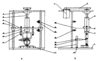
Fig. 1 is a structural representation of the present invention;
Wherein: a is a front view, and b is a side view.
Embodiment
Below embodiments of the invention are elaborated, present embodiment is being to implement under the prerequisite with the technical solution of the present invention, provided detailed embodiment and concrete operating process, but protection scope of the present invention is not limited to following embodiment.
Shown in Fig. 1 a and Fig. 1 b, present embodiment comprises: frame 1, transmission pressing mechanism 2 and stress loop location-plate 3, wherein: stress loop location-plate 3 is horizontally placed on frame 1 bottom, and transmission pressing mechanism 2 is positioned at frame 1 and is vertically installed in stress loop location-plate 3 tops.
Described transmission pressing mechanism 2 comprises: stepping motor 4, synchronous belt drive mechanism 5, upright driving mechanism 6 and connection pressing mechanism 7, wherein: stepping motor 4 is fixedly set in frame 1 top and links to each other with an end of synchronous drive mechanism 5, the other end of synchronous belt drive mechanism 5 is connected with upright driving mechanism 6, upright driving mechanism 6 vertically is arranged at frame 1 top, connect pressing mechanism 7 and be fixedly set in the lower end of upright driving mechanism 6, and be positioned at the top of the stress loop of waiting to pressurize.
Described upright driving mechanism 6 comprises: ball guide screw nat 8, slide carriage 9, line slideway 10, bearing external member 11 and optical axis 12, wherein: two line slideways 10 vertically are arranged in the frame 1 respectively, bearing external member 11 is fixedly set between the line slideway 10, ball guide screw nat 8 is socketed in the bearing external member 11 and with synchronous belt drive mechanism 5 and links to each other, slide carriage 9 horizontal fixed be arranged at ball guide screw nat 8 the lower end and with two line slideway 10 sliding contacts, two optical axises 12 vertically be arranged at respectively slide carriage 9 the lower surface and with connect pressing mechanism 7 and link to each other.
Described connection pressing mechanism 7 comprises: pressure transducer 13 and pressurization external member 14.Pressure transducer 13 is fixed on the lower surface of slide carriage 9, and pressurization external member 14 is fixed on the lower end of optical axis 12.
Be provided with anti-twist mechanism 15 and safe position-limit mechanism 16 in the described frame 1, wherein: anti-twist mechanism 15 and safe position-limit mechanism 16 vertically are arranged in the frame 1 and are parallel to transmission pressing mechanism 2 respectively.
Described anti-twist mechanism 15 comprises: straight-bar 17, adjusting slider 18 and clamp 19, and wherein: straight-bar 17 vertically is fixedly set on the frame 1, and adjusting slider 18 is socketed on the straight-bar 17 and with clamp 19 fixedlys connected, and clamp 19 contact with test specimen in the stress loop.
Described safe position-limit mechanism 16 comprises: inductive switch 20, limit switch 21 and sheet metal 22, wherein: two groups of inductive switches 20 and limit switch 21 are fixedly set in the high-low limit position of transmission pressing mechanism 2 on the frame 1 respectively, sheet metal 22 is fixedly set on the slide carriage 9, and do the motion of vertical direction with slide carriage 9, the detected object of double as inductive switch 20 and stroke dog guarantee that slide carriage 9 strokes are no more than the high-low limit position.
Introduce the course of work of present embodiment with reference to the accompanying drawings: before stress loop loaded beginning, slide carriage 9 was positioned at the limes superiors position, and stress loop correctly is installed on the location-plate 3, with anti-twist mechanism 15 test specimen was fixed.Control step motor 4 drive synchronous belt drive mechanisms 5 with transmission of power to ball guide screw nat 8 and drive the ball-screw rotation, make feed screw nut drive slide carriage 9, pressure transducer 13, optical axis 12 and pressurization external member 14 and move downward along line slideway 10 together, pressurization external member 14 is contacted with stress loop and keep this state constant.Ball guide screw nat 8 continues to drive slide carriage 9 and pressure transducer 13 moves downward, and contact with pressurization external member 14 until pressure transducer 13, and the counter stress circulating application adds load.When reaching required on-load pressure, stepping motor 4 stalls, the staff with test specimen be tightened finish after, stepping motor 4 counter-rotating drives slide carriages 9, pressure transducer 13 and pressurization external member 14 and moves upward and get back to initial limes superiors position, finishes loading procedure like this one time.
Compared with prior art, present embodiment has following characteristics: 1, Zhuan Yong stress loop charger, to compare with general tension tester, and features simple structure is easily gone, and expense is low; 2, adopts pressure sensor is measured counter stress ring institute applied pressure in real time, has replaced available technology adopting clock gauge Displacement Measurement to measure the method for stress loop on-load pressure indirectly, and not only precision height, and real-time is good, is easy to the testing crew operation.
Claims (5)
1. the automatic loading device of stress ring of anti-H 2 S stress corrosion test, comprise: frame, transmission pressing mechanism and stress loop location-plate, wherein: the stress loop location-plate is horizontally placed on the frame bottom, the transmission pressing mechanism is positioned at frame and is vertically installed in stress loop location-plate top, it is characterized in that:
Described transmission pressing mechanism comprises: stepping motor, synchronous belt drive mechanism, upright driving mechanism and connection pressing mechanism, wherein: stepping motor is fixedly set in upper rack and links to each other with an end of synchronous belt drive mechanism, the other end of synchronous belt drive mechanism is connected with upright driving mechanism, upright driving mechanism vertically rotates and is arranged at upper rack, and the connection pressing mechanism is fixedly set in the lower end of upright driving mechanism and contacts with stress loop to be measured;
Described upright driving mechanism comprises: ball guide screw nat, slide carriage, line slideway, bearing external member and optical axis, wherein: two line slideways vertically are arranged in the frame respectively, the bearing external member is fixedly set between the line slideway, ball guide screw nat is socketed in the bearing external member and with synchronous belt drive mechanism and links to each other, the slide carriage horizontal fixed be arranged at ball guide screw nat the lower end and with two line slideway sliding contacts, two optical axises vertically be arranged at respectively slide carriage the lower surface and with connect pressing mechanism and link to each other.
2. the automatic loading device of stress ring of anti-H 2 S stress corrosion test according to claim 1, it is characterized in that, described connection pressing mechanism comprises: pressure transducer and pressurization external member, and wherein: pressure transducer is fixed on the lower surface of slide carriage, and the pressurization external member is fixed on the lower end of optical axis.
3. the automatic loading device of stress ring of anti-H 2 S stress corrosion test according to claim 1, it is characterized in that, be provided with anti-twist mechanism and safe position-limit mechanism in the described frame, wherein: anti-twist mechanism and safe position-limit mechanism vertically are arranged in the frame and are parallel to the transmission pressing mechanism respectively.
4. the automatic loading device of stress ring of anti-H 2 S stress corrosion test according to claim 3, it is characterized in that, described anti-twist mechanism comprises: straight-bar, adjusting slider and clamp, wherein: straight-bar vertically is fixedly set on the frame, adjusting slider is socketed on the straight-bar and with clamp fixedlys connected, and clamp contact with the transmission pressing mechanism.
5. the automatic loading device of stress ring of anti-H 2 S stress corrosion test according to claim 3, it is characterized in that, described safe stop means comprises: inductive switch, limit switch and sheet metal, wherein: the high-low limit position of transmission pressing mechanism is set with one group of inductive switch and limit switch respectively on the frame, sheet metal is fixedly set on the slide carriage, and does the motion of vertical direction with slide carriage.
Priority Applications (1)
| Application Number | Priority Date | Filing Date | Title |
|---|---|---|---|
| CN2010101087540A CN101793653B (en) | 2010-02-11 | 2010-02-11 | Automatic loading device of stress ring |
Applications Claiming Priority (1)
| Application Number | Priority Date | Filing Date | Title |
|---|---|---|---|
| CN2010101087540A CN101793653B (en) | 2010-02-11 | 2010-02-11 | Automatic loading device of stress ring |
Publications (2)
| Publication Number | Publication Date |
|---|---|
| CN101793653A CN101793653A (en) | 2010-08-04 |
| CN101793653B true CN101793653B (en) | 2011-11-16 |
Family
ID=42586466
Family Applications (1)
| Application Number | Title | Priority Date | Filing Date |
|---|---|---|---|
| CN2010101087540A Expired - Fee Related CN101793653B (en) | 2010-02-11 | 2010-02-11 | Automatic loading device of stress ring |
Country Status (1)
| Country | Link |
|---|---|
| CN (1) | CN101793653B (en) |
Families Citing this family (9)
| Publication number | Priority date | Publication date | Assignee | Title |
|---|---|---|---|---|
| CN102156186B (en) * | 2010-12-28 | 2014-10-22 | 同济大学 | Temperature-controlled unsaturation high-pressure consolidometer |
| CN102636145B (en) * | 2012-04-10 | 2014-03-26 | 上海交通大学 | Automatic detection device for roundness of end part of special steel pipe and detection method thereof |
| CN103033415B (en) * | 2013-01-03 | 2014-09-17 | 中国人民解放军国防科学技术大学 | Loading device and loading method for expansion loop |
| CN103364287B (en) * | 2013-07-02 | 2015-08-12 | 上海交通大学 | A kind of anti-H 2 S stress corrosion test loading method |
| CN108507712A (en) * | 2017-05-23 | 2018-09-07 | 太仓市伦文机械有限公司 | A kind of stress test equipment |
| CN108693038B (en) * | 2018-07-24 | 2023-07-14 | 鞍山星源达科技有限公司 | Automatic load loading device and method for metallurgical or coked material performance measurement experiment |
| CN110006561A (en) * | 2019-05-10 | 2019-07-12 | 南京工程学院 | A kind of device of roller bolt stress in the around-France measurement feed screw nut of stress |
| CN110125274B (en) * | 2019-06-03 | 2020-11-06 | 沈阳天贺新材料开发有限公司 | Automatic ring expanding equipment for producing memory ring |
| CN111678805B (en) * | 2020-05-11 | 2023-03-24 | 江苏禹治流域管理技术研究院有限公司 | Device and method for testing dynamic shear strength of rock based on SHPB (shepherd-type-shear-stress-reduction) |
Citations (3)
| Publication number | Priority date | Publication date | Assignee | Title |
|---|---|---|---|---|
| EP0297643A1 (en) * | 1987-07-02 | 1989-01-04 | SKF Industrial Trading & Development Co, B.V. | Method and device for examining the wear and friction properties of surface materials exposed to sliding friction |
| CN1274840A (en) * | 1999-05-21 | 2000-11-29 | 浙江工业大学 | Automatically loading small-force test equipment with elastic pressure head |
| CN2809627Y (en) * | 2005-07-04 | 2006-08-23 | 长安大学 | Corrosion fatigue tester |
-
2010
- 2010-02-11 CN CN2010101087540A patent/CN101793653B/en not_active Expired - Fee Related
Patent Citations (3)
| Publication number | Priority date | Publication date | Assignee | Title |
|---|---|---|---|---|
| EP0297643A1 (en) * | 1987-07-02 | 1989-01-04 | SKF Industrial Trading & Development Co, B.V. | Method and device for examining the wear and friction properties of surface materials exposed to sliding friction |
| CN1274840A (en) * | 1999-05-21 | 2000-11-29 | 浙江工业大学 | Automatically loading small-force test equipment with elastic pressure head |
| CN2809627Y (en) * | 2005-07-04 | 2006-08-23 | 长安大学 | Corrosion fatigue tester |
Also Published As
| Publication number | Publication date |
|---|---|
| CN101793653A (en) | 2010-08-04 |
Similar Documents
| Publication | Publication Date | Title |
|---|---|---|
| CN101793653B (en) | Automatic loading device of stress ring | |
| CN102175528B (en) | Bearing test device for multifunctional plate | |
| CN201653826U (en) | Device for two-way tensile creep test of sealant | |
| CN101832901B (en) | Contact-type frictional interface stick-slip characteristic on-line detection device | |
| CN102692200B (en) | Device for automatically detecting spool displacement of electromagnetic valve with high precision and method thereof | |
| CN101943646A (en) | Full-automatic horizontal electronic tension tester | |
| CN208805157U (en) | A kind of hub detection device | |
| CN210376086U (en) | Sliding friction measuring device | |
| CN102539238A (en) | Precision-grade material tension and compression stiffness tester | |
| CN109490079A (en) | A kind of reinforcement property detection device | |
| CN105527174B (en) | A kind of measuring device of biologic soft tissue mechanical property | |
| CN209355838U (en) | A kind of detection device for bearing end-play | |
| CN102116717A (en) | Material testing machine-based ball screw assembly axial static stiffness testing clamp | |
| CN203024854U (en) | Automatic pressure preloading equipment for weighing force transducer | |
| CN201811890U (en) | Full-automatic horizontal electronic tension tester | |
| CN202119681U (en) | Bending creep testing machine for GRP (Glass Reinforced Plastics) | |
| CN209296474U (en) | A kind of reinforcement property detection device | |
| CN104613847B (en) | The detection device in sliding rail of automobile seat gap | |
| CN216815820U (en) | Ball screw pair friction moment measuring equipment | |
| CN110530739B (en) | Full-automatic four-linkage strain control type direct shear apparatus | |
| CN209589312U (en) | A kind of pull force calculation equipment | |
| CN109142052B (en) | Precise test equipment for rigidity and elastic hysteresis effect of beryllium bronze leaf spring | |
| CN110044699A (en) | A kind of material compression test and collecting method | |
| CN209182156U (en) | Knob three-dimensional pressure test machine | |
| CN110333143A (en) | Test machine |
Legal Events
| Date | Code | Title | Description |
|---|---|---|---|
| C06 | Publication | ||
| PB01 | Publication | ||
| C10 | Entry into substantive examination | ||
| SE01 | Entry into force of request for substantive examination | ||
| C14 | Grant of patent or utility model | ||
| GR01 | Patent grant | ||
| C17 | Cessation of patent right | ||
| CF01 | Termination of patent right due to non-payment of annual fee |
Granted publication date: 20111116 Termination date: 20140211 |