CN101789972A - Network communication node - Google Patents
Network communication node Download PDFInfo
- Publication number
- CN101789972A CN101789972A CN201010105267A CN201010105267A CN101789972A CN 101789972 A CN101789972 A CN 101789972A CN 201010105267 A CN201010105267 A CN 201010105267A CN 201010105267 A CN201010105267 A CN 201010105267A CN 101789972 A CN101789972 A CN 101789972A
- Authority
- CN
- China
- Prior art keywords
- mac address
- frame
- zone
- mac
- handling part
- Prior art date
- Legal status (The legal status is an assumption and is not a legal conclusion. Google has not performed a legal analysis and makes no representation as to the accuracy of the status listed.)
- Pending
Links
Images


Classifications
-
- H—ELECTRICITY
- H04—ELECTRIC COMMUNICATION TECHNIQUE
- H04L—TRANSMISSION OF DIGITAL INFORMATION, e.g. TELEGRAPHIC COMMUNICATION
- H04L43/00—Arrangements for monitoring or testing data switching networks
- H04L43/10—Active monitoring, e.g. heartbeat, ping or trace-route
-
- H—ELECTRICITY
- H04—ELECTRIC COMMUNICATION TECHNIQUE
- H04L—TRANSMISSION OF DIGITAL INFORMATION, e.g. TELEGRAPHIC COMMUNICATION
- H04L43/00—Arrangements for monitoring or testing data switching networks
- H04L43/50—Testing arrangements
-
- H—ELECTRICITY
- H04—ELECTRIC COMMUNICATION TECHNIQUE
- H04L—TRANSMISSION OF DIGITAL INFORMATION, e.g. TELEGRAPHIC COMMUNICATION
- H04L45/00—Routing or path finding of packets in data switching networks
- H04L45/22—Alternate routing
-
- H—ELECTRICITY
- H04—ELECTRIC COMMUNICATION TECHNIQUE
- H04L—TRANSMISSION OF DIGITAL INFORMATION, e.g. TELEGRAPHIC COMMUNICATION
- H04L45/00—Routing or path finding of packets in data switching networks
- H04L45/28—Routing or path finding of packets in data switching networks using route fault recovery
-
- H—ELECTRICITY
- H04—ELECTRIC COMMUNICATION TECHNIQUE
- H04L—TRANSMISSION OF DIGITAL INFORMATION, e.g. TELEGRAPHIC COMMUNICATION
- H04L45/00—Routing or path finding of packets in data switching networks
- H04L45/50—Routing or path finding of packets in data switching networks using label swapping, e.g. multi-protocol label switch [MPLS]
-
- H—ELECTRICITY
- H04—ELECTRIC COMMUNICATION TECHNIQUE
- H04L—TRANSMISSION OF DIGITAL INFORMATION, e.g. TELEGRAPHIC COMMUNICATION
- H04L45/00—Routing or path finding of packets in data switching networks
- H04L45/54—Organization of routing tables
-
- H—ELECTRICITY
- H04—ELECTRIC COMMUNICATION TECHNIQUE
- H04L—TRANSMISSION OF DIGITAL INFORMATION, e.g. TELEGRAPHIC COMMUNICATION
- H04L45/00—Routing or path finding of packets in data switching networks
- H04L45/66—Layer 2 routing, e.g. in Ethernet based MAN's
-
- H—ELECTRICITY
- H04—ELECTRIC COMMUNICATION TECHNIQUE
- H04L—TRANSMISSION OF DIGITAL INFORMATION, e.g. TELEGRAPHIC COMMUNICATION
- H04L45/00—Routing or path finding of packets in data switching networks
- H04L45/68—Pseudowire emulation, e.g. IETF WG PWE3
-
- H—ELECTRICITY
- H04—ELECTRIC COMMUNICATION TECHNIQUE
- H04L—TRANSMISSION OF DIGITAL INFORMATION, e.g. TELEGRAPHIC COMMUNICATION
- H04L2101/00—Indexing scheme associated with group H04L61/00
- H04L2101/60—Types of network addresses
- H04L2101/618—Details of network addresses
- H04L2101/622—Layer-2 addresses, e.g. medium access control [MAC] addresses
Landscapes
- Engineering & Computer Science (AREA)
- Computer Networks & Wireless Communication (AREA)
- Signal Processing (AREA)
- Health & Medical Sciences (AREA)
- Cardiology (AREA)
- General Health & Medical Sciences (AREA)
- Small-Scale Networks (AREA)
Abstract
The invention addresses reducing time taken to obtain destination MAC addresses or alleviating the workload of manually setting MAC addresses in physical ports for duplicate PtP connections in WAN. A physical port (1001) is provided with functionality (1002, 1003) that, when transmitting a data frame received by the transmission block (702) in the physical port, copies the content of the source MAC address field in the received data frame to the destination MAC address field, selects a destination MAC address randomly, or specifies a fixed value which has been set beforehand as the destination MAC address. The port is also provided with functionality (709, 712, 713) that performs receive processing on a data frame after being received by the reception block without inspecting the destination MAC address field in the MAC header. Thereby, the time to obtain addresses is reduced or the setting workload is lessened.
Description
Technical field
The present invention relates to meet the network communication device of the standard specification of in data communication, using, particularly relate to the communication port structure of carrying out the network communication device of data transmit-receive by point-to-point connection.
Background technology
As in the building, waiting in the zone that is restricted on the geography, the various device that is connected can freely interconnective network, be one of communication technology in the LAN (Local Area Network), have Ethernet (registered trade mark) technology (with reference to non-patent literature 1).Nineteen eighty-three in IEEE (U.S. electric institute of electronics), be standardized as 802.3CSMA/CD (Carrier Sense Multiple Access withCollosion Detection), one of its feature is that bus-type connects communication mode.
So-called bus-type is meant the communication mode by the public data transfer path of multiple arrangement.The Frame that sends from certain device is received by all devices in common transport path.In bus-type, when plural device sends Frame simultaneously,, these Frames produce loss, so the problem that exists the efficiency of transmission of Frame to reduce according to frame when producing conflicting hours.Having point-to-point (PtP) in the connected mode that can avoid this problem connects.
Ethernet technology, from initial communication speed 10Mbps (Mega bit per second), the specification that is turned to 100Mbps, 1Gbps (Giga bps) at a high speed has been normalized to 10Gbps at present by standardization.Accompany therewith, application comes to WAN (Wide Area Network) expansion from LAN.
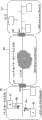
So-called WAN is meant the network of wide area geographically than LAN, for example shown in 103 of Fig. 1, be meant the LAN101 that connected the P branch store that is positioned at tens of meters scopes and the same Q branch store LAN102 etc., the network that between the dotted LAN that is far apart mutually, connects geographically.WAN103 is the network that connects each other between the long distance LAN of (thousands of rice~hundreds of kms), general, and the gateway (GW) 104,105 of the device of representing each LAN is set, and only should connect between GW.In addition, when connecting between a plurality of LAN, when a plurality of GW being carried out the bus-type connection, because the time ratio LAN length that Frame exists on transmission path, so produce the probability height of Frame conflict, data transmission efficiency is lower than LAN.At this moment, adopt such connected mode: that is, relay is set, to connect relay than distance short between GW between GW.In this connects, using in the bus-type, also using relay is connected with the above-mentioned PtP that GE is connected one to one.
In this PtP connects because on a transmission path, only there are two devices, so in the full-duplex communication that can receive and dispatch simultaneously, the collision probability of Frame becomes 0.When being WAN, constitute junction network (trunk network) by multistage connection relay, generally carry out the PtP connection between the device but continue in these.Generally in LAN, use Internet Protocol (IP) in the communication, also use IP in the relay of the WAN that between to LAN, connects.When using IP, the IP address intrinsic to the terminal distribution that communicates, in each Frame, need in MAC (MediaAccess Control) head, record and narrate and send the destination MAC Address, send source MAC, also, its communication port is distributed intrinsic IP address at the relay of WAN.
But, owing to give IP the address, will produce from the tool user with harmful intent of outside and can carry out problem on the safety such as Denial of Service attack of having used ICMP (Internet Control Message Protocol) communicator, so, but increasing day by day by situation about manually setting not to the communication port distributing IP address of carrying out the Frame transmitting-receiving of relay.
This is because when having the IP address in communication port, can be according to IP routing protocol, ICMP or ARP (An Ethernet Address Resolution Protocol) (with reference to non-patent literature 2,3), the IP address that connects the destination from PtP obtains the transmission destination MAC Address (MAC address learning) that PtP connects the destination, by using this MAC address learning, can in each relay, automatically obtain the MAC Address that PtP connects the destination, carry out the relaying of Frame.
The thick body of [non-patent literature 1] IP ネ ッ ト ヮ one Network bodyguard, aboveground hero, this real of Ri industry publishing house, pp58~59,66~73,76~81,146~161,166~169,178~185 of stretching
[non-patent literature 2] ARP, An EthernetAddress Resolution Protocol,
Http:// tools
.ietf.org/html/rfc826
[non-patent literature 3] ICMP, INTERNET CONTROL MESSAGE PROTOCOL,
Http:// tools.ietf.org/html/rfc792
PtP between the relay of above-mentioned WAN connects general distance and grow (thousands of rice~tens of kms), so for the fault of guarding against transmission cables such as broken string etc., many times adopt the two-fold structure of two PtP connections of use between same device.When being the two-foldization structure, a side is used for data communication as current using system, the opposing party as the preparation system, is switched when having produced certain fault in current using system and used.Switch needed time t about this, begin to be made as t1 when fault has been taken place certain place from transmission path up to the time that in relay, detects this fault, the communication port that is used for data communication in relay is made as t2 from the time that current using system switches to the preparation system, the needed time of acquisition that the PtP that the communication port that newly becomes current using system is used in data frame transfer connects the MAC Address (sending the destination MAC Address) of destination is when being made as t3, shows by t=t1+t2+t3 roughly.Because t short transmission more is short more time of delay, thus require to shorten t, but in ethernet technology especially the shortening of t3 be a problem always.
In addition, when distributing IP address not, need by manually setting the MAC Address that PtP connects the destination.But,, become sizable workload by the MAC Address of manually not setting the connection destination of this PtP mistakenly for whole communication port of whole relays.Because in a relay, exist usually from tens of to the communication port more than 100, so need to confirm whether these each ports have all inerrably been set MAC Address.This affirmation is carried out in the following manner: be sent in and send the Frame that the PtP that has recorded and narrated manual setting in the MAC Address zone, destination connects the MAC Address of destination, confirm can receive this Frame in the device of PtP connection destination.Then, carry out this affirmation operation in whole communication port.
And, because plant failure etc. when having changed certain relay, is not only the device of replacing, also need this PtP is connected a plurality of relays of destination, by manually inerrably resetting the MAC Address of the device after the replacing, so workload increases several times.That is,, can produce operation for these relays of 10 carrying out relay that PtP is connected when being 10 with the device of changing object.Alleviate this workload and just become problem.
The relay that constitutes junction network (net) can be categorized as following two kinds.One is the edge device that is connected with a plurality of LAN, and another is the core apparatus that connects between edge device.Core apparatus can also be connected with other core apparatus.Between LAN and the edge device, between edge device and the core apparatus and between the core apparatus, generally be that PtP connects, but also have the situation that bus-type connects.When the connection change of at every turn carrying out between bus-type connection and the PtP connection, displacement apparatus just becomes problem at economic aspect.Therefore, need freely to carry out connecting change or the change opposite that connects to bus-type with it from PtP.That is, obtain to send under the situation of the time that MAC Address spent realizing under PtP connects, shortening, perhaps under the situation that has realized alleviating the workload by manual setting MAC Address, need also to realize that bus-type connects.
Summary of the invention
First problem of the present invention is to provide a kind of network communication device, and it can shorten the needed time of acquisition of the transmission destination MAC Address of the feature that connects as bus-type.
In addition, second problem of the present invention is to provide a kind of network communication device, and it can alleviate by manually to the workload of the ports-settings MAC Address of relay.
And, the 3rd problem of the present invention is to provide a kind of network communication device, it is under the situation that has realized the time that shortening acquisition transmission destination MAC Address is spent under PtP connects, perhaps under the situation that has realized alleviating the workload by manual setting MAC Address, can also realize that bus-type connects.
In Ethernet PtP connection, sending before the Frame, because need to obtain the MAC Address that PtP connects the destination, so produce above-mentioned first problem of the present invention and second problem.Therefore, first and second problems can solve by same means.
In the present invention, as first means that are used to solve first and second problems, possess when the communication port at Ethernet sends Frame, the means in the transmission source MAC zone in sending destination MAC Address region duplication Frame, perhaps possess at random the means of selecting to send the destination MAC Address, perhaps possess make prior setting intrinsic value as the means that send the destination MAC Address.And, possess after receiving Frame, do not check the MAC Address zone, transmission destination of MAC head, that is, do not learn the means that MAC Address ground receives processing.
Perhaps, as the second means that is used to solve first and second problems, possess in the communication port of Ethernet, after this communication port is connected the destination with PtP communication port has begun to connect, perhaps periodically be sent in the means of the Ethernet test frame that sends the MAC Address of having recorded and narrated self in the source MAC zone.And, possess after receiving described Ethernet test frame, means from the data source MAC Address extracted region MAC Address of this frame, also possess when sending Frame, till this PtP connection is cut off, be used for this MAC Address is connected as PtP the mac address learning table of the transmission destination MAC Address use of destination.
And, in the present invention, in order to solve the 3rd problem, possess when in the communication port of Ethernet, sending Frame, sending the effective/invalid means of switching of destination MAC Address search function.In addition, possess after receiving Frame, that MAC Address of recording and narrating in the MAC Address zone with the MAC head and predefined MAC Address compare, to receiving filtration function effectively/the invalid switch means of switching.And, possess the switching interface that can operate described two switch means from Control Server.
According to the present invention, in the two-fold structure that PtP connects, can shorten the needed time of two-foldization switching.
In addition, when between device, carrying out the PtP connection, need manually not set the operation of the MAC Address that connects the destination in advance for carrying out the communication port that PtP connects.
And, can be provided in when connecting and can realize two above-mentioned effects for PtP, and when bus-type connects can with the interconnective ethernet communication device of the device of having used general ethernet technology.
Description of drawings
Fig. 1 is used to illustrate the relation of LAN and WAN.
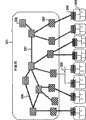
Fig. 2 is used to illustrate an example of network configuration.
Fig. 3 is illustrated in an example of the form of the Frame that flows in the network.
Fig. 4 represents a configuration example of label switch hardware.
Fig. 5 represents the setting example of the label switched path of label switch.
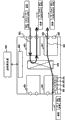
Fig. 6 represents the two-fold example of structure based on the PtP connection of label switch.
Fig. 7 represents the structure of general ethernet communication device.
Fig. 8 has represented the example of mac address learning table of the structure of Fig. 7.
Fig. 9 has represented an example that the side ports key of the structure of Fig. 7.
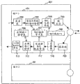
Figure 10 represents the ethernet communication apparatus structure of first embodiment.
Figure 11 represents the ethernet communication apparatus structure of second execution mode.
Figure 12 represents the example of the mac address learning table in the ethernet communication apparatus structure of second execution mode.
Figure 13 represents the structure of the ethernet communication device of the 3rd embodiment.
Figure 14 is used to illustrate that the ethernet frame of first embodiment sends processing.
Figure 15 is used to illustrate the order that the received frame of first embodiment is handled.
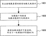
Figure 16 is used to illustrate that the retrieval of the 3rd embodiment switches invalid setting.
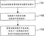
Figure 17 is used to illustrate the effectively setting of retrieval switching of the 3rd embodiment.
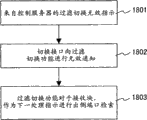
Figure 18 is used to illustrate that the filtration of the 3rd embodiment switches invalid setting.
Figure 19 is used to illustrate the effectively setting of filtration switching of the 3rd embodiment.
The explanation of symbol
301MAC head, 302 " pad " head, 303IP head, 304 data, 305 labels, 306 send destination MAC Address, 307 and send source MAC, 401IF card, 402 communication port, 403 inner exchanging machines, 404 control cards, 501 label switched paths
Embodiment
Below use accompanying drawing that embodiments of the present invention are described in detail.In the following description, please note sometimes and to wait the routine processes in the handling part (Central Processing Unit:CPU) to show as " function ", " piece " or " portion " on interface (IF) card.
Fig. 2 is the network structure that becomes the prerequisite of each execution mode.Represent the GW204 of each LAN205 to connect via trunk network 201.Trunk network 201 is made of the edge device 203 of accommodating GW203, the core apparatus 202 that connects between edge device 203.Carry out bus-type connection 208 or PtP and connect between GW204 and edge device 203, carry out PtP and connect 206 between edge device and core apparatus or core apparatus, a part has been carried out PtP and has been connected two-foldization 207.Between the present invention and this edge device 203 and the core apparatus 202 or the PtP between the core apparatus 202 connect 206 and PtP to connect two-foldization 207 relevant.
Fig. 3 represents in the LAN, in the frame format of using between GW and the edge device, the frame format used between edge device and core apparatus or core apparatus." pad " head (shim header) 302 gives in edge device or deletes, and comprises label 305.In core apparatus, replace sending the destination MAC Address and use this label 305, select transmit port.In Fig. 3,301 is that MAC head, 303 is that IP head, 304 is that data, 306 are the transmission MAC Address, and 307 are the transmission source MAC.
Fig. 4 represents a concrete structure of edge device 203, core apparatus 202.The control card 404 that IF card 401 or inner exchanging machine 403 are controlled that device communicates by the communication port 402 in 401 groups on IF card, the IF card, inner exchanging machine 403, with outside Control Server 405 constitutes.IF card 401 is by as the central processing department (CPU) of handling part performance function, as the memory of the storage part of various tables of storage or data, constitute as the PHY/MAC of physical port portion.This PHY is a physical layer transceiver, carries out ethernet frame described later and handles.MAC is the media access controller of IEEE802.3 specification benchmark at this.CPU in the IR card 401 receives the indication from Control Server 405 via control card 404, carries out various routine processes.Inner exchanging machine 403 is also identical, is controlled by Control Server 405 via control card.
How Fig. 5 sets label switched path in order to illustrate in edge device, illustrates an example, and the 501st, label switched path.In addition, also represent to input to the data frame format of edge device 203 simultaneously.In inputing to the Frame of edge device, two kinds that have common ethernet frame and added MPLS (the Multi Protocol Label Switching) frame of " pad " head (shimheader).When having imported ethernet frame, be the MPLS frame in the inner conversion of IF card, carry out transmission process then.On the other hand, when having imported the MPLS frame, directly carry out transmission process as the MPLS frame.
Inner exchanging machine 403 transmits this MPLS frame with reference to the label 305 that exists to the communication port of outlet in " pad " head (shim header) 302 of MPLS frame.In the communication port of outlet, judge it is directly to send the MPLS frame according to the device that connects the destination, still carry out conversion, transferring data frames then to ethernet frame.When being core apparatus 202, except input and output all are the MPLS frame, identical with edge device 203.In the following description, comprise also that sometimes the device that has with reference to the inner exchanging machine of tag transmits MPLS frame is called the label switch.
Fig. 6 is a connection layout between edge device and core apparatus shown in Figure 5 or the device when taking PtP to connect the two-foldization structure between core apparatus.In Fig. 6, between IF card Z1, the Z2 of IF card A3, the A4 of label switch A601 and label switch Z602, set two PtP and connected.Usually executive communication in the working side path 603 (solid line) between the IF card Z1 of the IF card A3 of label switch A601 and label switch Z602, taken place under the situation of fault when for example the cable between jockey is cut off etc., switched communication path to protection side path 604 (dotted line).By this handoff functionality, though taken place fault also can not cut off proceed communicatedly communication.General transfer sequence below is described.
In Fig. 6, set from IF card A2 to IF card A3 and to two label switched paths of IF card A4.The Frame of importing to IF card A2 is transmitted to inner switch, inner exchanging machine copied data frames, other direction A4 is transmitted in wherein direction A3 transmission.From omitting illustrated control card notice IF card A3, A4 self is the working side, or protection one side, and the working side is carried out common Frame and sent processing, and the discarded Frame of protection side.When if the IF card A3 of working side detects fault, then break down to the control card notice immediately.Control card sends to the IF of protection side card A4 indication beginning Frame immediately and handles.The IF card A4 that receives the protection side of indication from control card begins to handle to the transmission of this obsolete Frame immediately.In this hand-off process, when handle is made as t1 from the actual beginning of breaking down up to the time that the IF of working side card A3 detects fault, notify fault the IF card A3 of working side to control card, control card is made as t2 to the time that the IF of protection side card A4 carries out Frame transmission indication, when the IF card A4 reality that receives indication is made as t3 from the time that communication port is sent Frame, then switching time t=t1+t2+t3.As mentioned above, when being Ethernet, shortening t3 and just become problem.
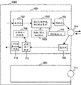
Fig. 7 represents the general IF card in edge device, the core apparatus and the logical construction of each communication port.As shown in Figure 4, in device, there are a plurality of IF cards 401, in an IF card 401, have a plurality of communication port 701.Generally between a plurality of IF cards, connect, also can between communication port, carry out the exchange of Frame even cross between the IF card by inner exchanging machine 403.In a communication port 701, carry out the transmission of Frame abreast and handle and receive processing.In Fig. 7, processing from left to right is send to handle, and processing from right to left is to receive to handle, each box indicating in the port 701 logic function corresponding etc. with each port.By sending the data that frame 702 is accepted, make 704 additional transmission destination MAC Address and the transmission source MAC a708 that use mac address learning tables 707 to retrieve by transmission MAC Address search function (portion) 703 by the MAC head, carry out frame then and send 705.In addition,, carry out filtration treatment, carry out address learning, its result is reflected in the mac address learning table 707 by sending source MAC learning functionality (portion) 711 by filtering 710 by the data that sink block 709 is accepted.In addition, use out side ports key 706 to retrieve side ports by going out side ports search function (portion) 712, make function (portion) 713 by " pad " head (shim header) and make " pad " head (shim header), send to inner exchanging machine 403 then.Going out side ports key 706, mac address learning table 707 is stored in the memory as storage part.
Fig. 8 is the example of mac address learning table 707.Corresponding with the numbering of each clauses and subclauses, be provided with the MAC Address hurdle and the life-span hurdle of study, from sign in to this table 707 beginning in that passing through should be after the time on life-span hurdle, this MAC Address of deletion from this table.
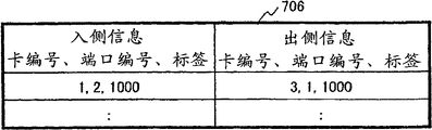
Fig. 9 is the example that side ports key 706.The side information of going into of so-called key 706 is meant the IF card numbering that receives certain Frame, the label that communication port is numbered, extracted from this frame.These as search key, are obtained out side information.Go out side information and be send the IF card numbering, communication port numbering of Frame, the label that should give this Frame.To have set in each hurdle of this table 706 in advance that these go into side information, go out side information is prerequisite.Usually, the operator by the supervisory relay net sets by manual input.
The network configuration of the prerequisite that becomes each embodiment more than has been described.Each embodiment below is described.
(embodiment 1)
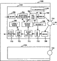
Figure 10 represents the IF card in the label switch of first embodiment and the structure of communication port.1000 IF card A3 corresponding to Fig. 6, the logic function of 1001 these ports of expression.When Frame arrive to send piece 702, the MAC head made, MAC Address copy function (portion) 1002, carried out that the MAC head makes or MAC Address is duplicated.In existing apparatus, as Fig. 7 explanation, make function (portion) 704 by the MAC head and set the MAC Address that obtains from mac address learning table 707 to sending MAC Address zone, destination, but in the present embodiment, by the MAC head make, MAC Address copy function (portion) 1002, set at random MAC Address fully for each Frame, perhaps set a fixed MAC address, perhaps the content in the transmission source MAC zone in the Frame that transmission destination MAC Address region duplication receives.For this reason, MAC Address function (portion) 1003 possesses the function of generation MAC Address at random at random/fixedly, perhaps is maintained fixed the function of MAC Address.Then, frame sends piece 705 and sets the transmission source MAC a708 that distributes in advance to sending the source MAC zone, sends this Frame from interface port 714.
In receiving processing, when Frame arrives when receiving pieces 709 from interface port 714, in going out side ports retrieval 712, " pad " head (shim header) r extracted region label from the Frame that receives, itself and IF card numbering, this communication port are numbered as search key, retrieve going out side ports key 706.Make in the function (portion) 713 at " pad " head (shim header), label area in " pad " head (shim header) of Frame writes the label that obtains, and sends to the IF card numbering that obtains as result for retrieval equally, the represented communication port of communication port numbering via the inner exchanging machine.At this moment, do not carry out any change to transmission destination MAC Address, transmission source MAC.That is, different with structure shown in Figure 7 in the present embodiment, do not filter and send the study of source MAC.
As above explanation is such, in existing apparatus, MAC Address has the function of recognition device, and whether consistent by investigating and send destination MAC Address and the MAC Address of self filtration treatment by filtering 710, whether the Frame that judgement receives is the Frame that sends to self.Therefore, can accept the Frame that all receives with not filtering.But, when connecting,, be to send to self so the data that receive all can be assumed to because can be a position with connecting the destination specific for PtP.Therefore, the possibility that the whole acceptance in ground have sent data is not filtered in existence.But, because exist connection destination device to send the possibility of unallied Frame mistakenly, so receive the Frame that should not receive at this moment.
At this, so-called unallied Frame is meant, the Frame beyond the predefined label switched path.That is, the Frame of having set the label value value in addition of predefined label switched path in the label field in " pad " head (shim header) is irrelevant, is the Frame that discard.In the present embodiment, these unallied Frames can not obtain result for retrieval when retrieving the side ports key, so go out of use in going out side ports retrieval 712.Therefore, can not appear at and not investigate in the filtration treatment whether send the destination MAC Address consistent with the MAC Address of self, and the problem of accepting the Frame that all receives.
Figure 14 represents to send based on the ethernet frame of the structure of present embodiment an example of the order of handling.In this example, the content in the transmission source MAC zone in the Frame that transmission destination MAC Address region duplication receives.When Frame arrives transmission piece 702 (1401), make the Ethernet head of this frame, in sending the source MAC zone, set the value a of MAC Address 708.Then, use the MAC Address copy function of piece 1002, duplicate transmission source MAC zone (1402) to sending the destination MAC Address.At last, send this Frame (1403) from interface port.Each Frame is carried out above-mentioned processing.In addition, can also replace sending source MAC,, set predefined fixed MAC address with MAC Address function 1003 at random/fixedly to sending destination MAC Address region duplication, or the MAC Address of generation at random.
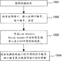
Figure 15 is based on the precedence diagram that the reception of ethernet frame of the structure of present embodiment is handled.When Frame arrives reception piece 709 (1501), " pad " head (shim header) extracted region label (1502) from Frame, itself and this IF card numbering, this communication port numbering as search key, are retrieved going out side ports key 706.The label that obtains is written in the label area of " pad " head in (shimheader) of Frame (1503), sends (1504) to the communication port of the IF card numbering that obtains as result for retrieval equally, the expression of communication port numbering via the inner exchanging machine.At this moment, do not carry out any change to transmission destination MAC Address, transmission source MAC.
Below, the effect of the embodiment 1 of explanation more than illustrating.In the structure of Fig. 7, in send handling with reference to mac address learning table 707.Constitute PtP by the current using system of swap data frame and the standby system that does not carry out data frames exchange fully and be connected two-foldization.In this standby system, because swap data frame not sends source MAC study so do not carry out, mac address learning table be a sky.Therefore, after the two-fold switching of switching current using system and standby system had just started, the mac address learning table of new current using system (standby system originally) was empty.Therefore, in the structure of Fig. 7, exist the transmission of Frame to be deferred to transmission source MAC study end in receiving processing, the problem of any MAC Address of login in mac address learning table always.Be included in this time of delay among the above-mentioned t3, in the present embodiment, because be in send handling not with reference to the structure of mac address learning table, so can shorten t3.
(embodiment 2)
Then, illustrate under the situation of reference mac address learning table, solve second embodiment of above-mentioned problem.
Figure 11 represents the IF card of second embodiment and the structure of communication port.Handle about sending, except common transmission is handled, also possess Ethernet test frame systematic function 1102.This function generates as sending the destination MAC Address and uses the broadcasting MAC Address that determines according to the Ethernet specification, and uses the Ethernet of the MAC Address a708 that in advance distributes to test frame as sending source MAC.And, have the state of monitoring interface port 714, be sent in the function that the Ethernet that generates when beginning is connected the connection of destination with PtP is tested frame from interface port 714.In addition, have after the connection that has begun to be connected the destination with PtP during cut, send the function of the Ethernet test frame that periodically generates from interface port 714.
This function by Fig. 4 described as the handling part in the IF card 401 CPU and carry out as the PHY/MAC of physical port portion.That is,, monitor the signal of telecommunication that flows on the Ethernet cable of place, when can be, become " connecting beginning " with relative device switching telecommunication as the PHY/MAC of physical port.On the contrary, when becoming can't be with relative device switching telecommunication the time, become " cut-out ".CPU monitors the state of this PHY/MAC, detects the connection that is connected the destination with PtP and begins, and carries out the transmission of Ethernet test frame.
Functional structure according to above-mentioned present embodiment, when PtP connects two-foldization, even in the preparation system that does not carry out the Frame transmission, also can test frame by switched ethernet, so the reception processing by Ethernet test frame can learn to send source MAC, can login MAC Address in mac address learning table 1103.Therefore, after just carrying out the two-fold switching, in mac address learning table 1103, login the MAC Address that PtP connects the destination, also can solve the problem of the transmission lag that has just carried out the Frame after the two-foldization switching in the present embodiment.
Figure 12 represents an example of the mac address learning table 1103 of Figure 11.In mac address learning table 1103, only set a MAC Address of learning, do not had the life-span hurdle that exists in the mac address learning table 707 of Fig. 8.Certainly, the MAC Address in this learning table 1103 also can have been learnt to finish before the switching of two-foldization.
(embodiment 3)
Figure 13 represents the structure of the communication port of the 3rd embodiment.It is the port function 1301 that has made up the structure of the general structure of Fig. 7 and first embodiment.In Figure 13, the processing route shown in the arrow of solid line is based on the processing route of the structure of Fig. 7, and the processing route shown in the arrow of two-wire is based on the processing route of the structure of embodiment 1.Each processing is identical with the explanation of Fig. 7, Figure 10.What append in the communication port structure of Figure 13 is to be used for from omitting retrieval handoff functionality (portion) 1303, the filtration handoff functionality (portion) 1304 that illustrated Control Server receives indication.Switching interface 1302 is to retrieval switching part 1303 and filter the indication that switching part 1304 notices give from Control Server.Retrieval switching part 1303 is for sending piece 702, carries out the switching controls of the processing that should carry out the Frame in the buffering.Similarly, filter switching part 1304, carry out the switching controls of the processing that should carry out for the Frame in the buffering for receiving piece 709.That is,, can realize in same device that the bus-type connection is connected with PtP by taking the structure of present embodiment.Below describe the details of the handoff procedure of present embodiment in detail by Figure 16~Figure 19.
Figure 16 is the precedence diagram of the execution of embodiment 3 when setting from the retrieval of Control Server is invalid.When having indicated invalid that retrieval switches from Control Server, switching interface 1302 receives this indications (1601).Switching interface 1302 is invalid (1602) to retrieval switching part 1303 indicative of settings.The retrieval switching part 1303 that receives indication is for arriving the whole Frame that sends piece 702 afterwards, and as next processing, setting is carried out the MAC head and made 1002 processing (1603).
Figure 17 is the precedence diagram of the execution of embodiment 3 when effectively setting from the retrieval of Control Server.When having indicated effective that retrieval switches from Control Server, switching interface 1302 receives this indications (1701).1302 pairs of retrievals of switching interface switching part, 1303 indicative of settings are effective (1702).The retrieval switching part 1303 that receives indication, is set and is sent destination MAC Address retrieval 703 (1703) as next processing for reaching the whole Frame that sends piece later on.
Figure 18 is the precedence diagram of the execution of embodiment 3 when setting from the filtration of Control Server is invalid.When having indicated from Control Server when filtering switch invalid, switching interface 1302 receives this indications (1801).It is invalid (1802) that 1302 pairs of switching interfaces filter switching part 1304 indicative of settings.The filtration switching part 1304 that receives indication as next processing, is set out side ports retrieval 712 (1803) for arriving the whole Frame that receives piece afterwards for.
Figure 19 is the precedence diagram of the execution of embodiment 3 when effectively setting from the filtration of Control Server.When having indicated from Control Server when filtering switch effective, switching interface 1302 receives this indications (1901).It is effective (1902) that 1302 pairs of switching interfaces filter switching part 1304 indicative of settings.The filtration switching part 1304 that receives indication, is set at and filters 710 (1903) as next processing for arriving the whole Frame that receives piece afterwards.
According to present embodiment, can in bus-type connection or PtP connection, use communication port according to switching indication from the Control Server device.
In the present embodiment, the port function after structure with Fig. 7 and Figure 10 makes up has been described, but has been not limited to this, for example can also be the port function after the structure that has made up Figure 10 and Figure 11.At this moment, structure by Figure 11, send the test frame, as the transmission destination MAC Address of in transmission, using, study also is kept at the original M AC address that extracts in the transmission source MAC zone from the Frame that relative device receives, can also be as the fixedly MAC Address of using in the port function of the structure of Figure 10.
The present invention who more than is described in detail can be used for network communication device effectively, particularly can be used for carrying out under PtP connects the network communication device of data transmit-receive effectively.
Claims (13)
1. network communication device, it has handling part, and transmitting-receiving has the Frame that sends the source MAC zone and send MAC Address zone, destination, it is characterized in that,
Described handling part, when the described Frame that transmission receives, control in this wise: that is the described transmission destination MAC Address region duplication in described Frame also sends the fixed value of preserving in advance.
2. network communication device according to claim 1 is characterized in that,
Described handling part, control in this wise: that is, when beginning or periodically be sent in the test frame of having recorded and narrated the MAC Address of in this device self, setting in the described transmission source MAC zone to described relative device with the communicating to connect of relative device at every turn.
3. network communication device according to claim 2 is characterized in that,
Described handling part, the MAC Address that extracts in the described transmission source MAC zone the described test frame that will receive from the transmission of the described test frame of correspondence is learnt and is preserved as the described fixed value of using when sending.
4. network communication device, it has handling part, and transmitting-receiving has the Frame that sends the source MAC zone and send MAC Address zone, destination, it is characterized in that,
Described handling part, when the described Frame that transmission receives, control in this wise: that is the described transmission destination MAC Address region duplication in described Frame also sends the content in the described transmission source MAC zone in the described Frame.
5. network communication device, it has handling part, and transmitting-receiving has the Frame that sends the source MAC zone and send MAC Address zone, destination, it is characterized in that,
Described handling part, when the described Frame that transmission receives, control in this wise: that is value is at random set and is sent in the MAC Address zone, described transmission destination in described Frame.
6. network communication device, it possesses a plurality of interface cards that are connected with switch is the IF card, transmitting-receiving has the Frame that sends the source MAC zone and send MAC Address zone, destination, it is characterized in that,
Described IF jig has handling part, storage part and physical port portion,
Described handling part, when sending from described Frame that described switch receives, so to retrieving the transmission destination MAC Address of the mac address learning table of in described storage part, storing, the described transmission destination MAC Address that use retrieves makes the MAC head, or the content in the described transmission source MAC zone in the described Frame that will receive, random value or the fixed value in advance set copy to described transmission destination-address zone, and this dual mode that makes described MAC head carries out switching controls.
7. network communication device according to claim 6 is characterized in that,
Whether described handling part when receiving described Frame, is kept at the switching controls of described mac address learning table after carrying out the described MAC Address in described transmission source MAC zone learnt.
8. network communication device according to claim 6 is characterized in that,
Described handling part according to from the outside control of device, is carried out described switching controls.
9. network communication device according to claim 7 is characterized in that,
Described handling part according to from the outside control of device, is carried out the described switching controls that whether is kept in the described mac address learning table.
10. network communication device according to claim 6 is characterized in that,
Described handling part, control in this wise: that is, in the described transmission source MAC zone of described Frame, record and narrate the MAC Address of in device self, setting in advance, send then.
11. network communication device according to claim 7 is characterized in that,
Described handling part, when receiving described Frame, according to the result that the described MAC Address in the MAC Address zone, described transmission destination of the described Frame that will receive and the MAC Address set in self in advance compare, whether decision is kept in the described mac address learning table after the described MAC Address in described transmission source MAC zone is learnt.
12. network communication device according to claim 7 is characterized in that,
Described handling part, be sent in the test frame of having recorded and narrated the MAC Address of setting in the described transmission source MAC zone in this device self to relative device, preserve as the transmission destination MAC Address of using when sending the original M AC address that will extract from the described transmission source MAC zone the Frame that described relative device receives.
13. network communication device according to claim 12 is characterized in that,
The connection with between the described relative device by described IF card is point-to-point connection.
Applications Claiming Priority (2)
| Application Number | Priority Date | Filing Date | Title |
|---|---|---|---|
| JP2009-015257 | 2009-01-27 | ||
| JP2009015257A JP2010177752A (en) | 2009-01-27 | 2009-01-27 | Network communication node |
Publications (1)
| Publication Number | Publication Date |
|---|---|
| CN101789972A true CN101789972A (en) | 2010-07-28 |
Family
ID=42078048
Family Applications (1)
| Application Number | Title | Priority Date | Filing Date |
|---|---|---|---|
| CN201010105267A Pending CN101789972A (en) | 2009-01-27 | 2010-01-26 | Network communication node |
Country Status (4)
| Country | Link |
|---|---|
| US (1) | US20100189114A1 (en) |
| EP (1) | EP2211509A3 (en) |
| JP (1) | JP2010177752A (en) |
| CN (1) | CN101789972A (en) |
Cited By (1)
| Publication number | Priority date | Publication date | Assignee | Title |
|---|---|---|---|---|
| CN103201982A (en) * | 2010-11-01 | 2013-07-10 | 惠普发展公司,有限责任合伙企业 | Managing MAC moves with secure port groups |
Families Citing this family (7)
| Publication number | Priority date | Publication date | Assignee | Title |
|---|---|---|---|---|
| US8059526B2 (en) * | 2009-03-23 | 2011-11-15 | Lsi Corporation | N+1 protection using a processor-based protection device |
| EP2530881B1 (en) * | 2011-06-27 | 2014-02-12 | Huawei Technologies Co., Ltd. | Media access control address protection method and switch |
| US9143391B2 (en) * | 2011-08-15 | 2015-09-22 | Mediatek Inc. | Method of processing management frame and related communication device |
| JP6219252B2 (en) * | 2014-09-29 | 2017-10-25 | 株式会社日立製作所 | One-way relay device |
| US9819596B2 (en) * | 2015-02-24 | 2017-11-14 | Qualcomm Incorporated | Efficient policy enforcement using network tokens for services C-plane approach |
| CN107241249B (en) * | 2017-05-19 | 2020-05-22 | 闫晓峰 | Ethernet bus switch, Ethernet bus system and data communication method |
| CN109327407B (en) * | 2018-08-08 | 2019-12-06 | 广东高云半导体科技股份有限公司 | data exchange device, data exchange method, computer device, and storage medium |
Citations (2)
| Publication number | Priority date | Publication date | Assignee | Title |
|---|---|---|---|---|
| US6779039B1 (en) * | 2000-03-31 | 2004-08-17 | Avaya Technology Corp. | System and method for routing message traffic using a cluster of routers sharing a single logical IP address distinct from unique IP addresses of the routers |
| CN101072162A (en) * | 2005-08-26 | 2007-11-14 | 北电网络有限公司 | Forwarding table minimization in Ethernet switch |
Family Cites Families (11)
| Publication number | Priority date | Publication date | Assignee | Title |
|---|---|---|---|---|
| JP3868815B2 (en) * | 2002-01-10 | 2007-01-17 | 富士通株式会社 | Communications system |
| JP4023281B2 (en) * | 2002-10-11 | 2007-12-19 | 株式会社日立製作所 | Packet communication apparatus and packet switch |
| JP2005175591A (en) * | 2003-12-08 | 2005-06-30 | Hitachi Cable Ltd | Switching hub |
| US7436832B2 (en) * | 2004-05-05 | 2008-10-14 | Gigamon Systems Llc | Asymmetric packets switch and a method of use |
| JP2006025121A (en) * | 2004-07-07 | 2006-01-26 | Fujitsu Ltd | Frame transfer method and device therefor |
| JP2006295550A (en) * | 2005-04-11 | 2006-10-26 | Mitsubishi Electric Corp | Packet transfer apparatus |
| US7486610B1 (en) * | 2005-05-11 | 2009-02-03 | Cisco Technology, Inc. | Multiple virtual router group optimization |
| JP4732987B2 (en) * | 2006-09-07 | 2011-07-27 | 株式会社日立製作所 | Packet transfer device |
| JP4347335B2 (en) * | 2006-12-18 | 2009-10-21 | 富士通株式会社 | Network relay program, network relay device, communication system, and network relay method |
| JP4773981B2 (en) * | 2007-01-12 | 2011-09-14 | 富士通株式会社 | Communication control program |
| US8077720B2 (en) * | 2007-02-27 | 2011-12-13 | Alcatel-Lucent Usa Inc. | Methods and devices for generating and forwarding translated MAC addresses |
-
2009
- 2009-01-27 JP JP2009015257A patent/JP2010177752A/en not_active Ceased
-
2010
- 2010-01-26 US US12/693,534 patent/US20100189114A1/en not_active Abandoned
- 2010-01-26 CN CN201010105267A patent/CN101789972A/en active Pending
- 2010-01-27 EP EP20100000833 patent/EP2211509A3/en not_active Withdrawn
Patent Citations (2)
| Publication number | Priority date | Publication date | Assignee | Title |
|---|---|---|---|---|
| US6779039B1 (en) * | 2000-03-31 | 2004-08-17 | Avaya Technology Corp. | System and method for routing message traffic using a cluster of routers sharing a single logical IP address distinct from unique IP addresses of the routers |
| CN101072162A (en) * | 2005-08-26 | 2007-11-14 | 北电网络有限公司 | Forwarding table minimization in Ethernet switch |
Cited By (1)
| Publication number | Priority date | Publication date | Assignee | Title |
|---|---|---|---|---|
| CN103201982A (en) * | 2010-11-01 | 2013-07-10 | 惠普发展公司,有限责任合伙企业 | Managing MAC moves with secure port groups |
Also Published As
| Publication number | Publication date |
|---|---|
| JP2010177752A (en) | 2010-08-12 |
| US20100189114A1 (en) | 2010-07-29 |
| EP2211509A3 (en) | 2010-08-18 |
| EP2211509A2 (en) | 2010-07-28 |
Similar Documents
| Publication | Publication Date | Title |
|---|---|---|
| CN101789972A (en) | Network communication node | |
| CN102017542B (en) | A method for interfacing a fibre channel network with an Ethernet based network | |
| EP1180883B1 (en) | Distributed source learning for data communication switch | |
| JP4547349B2 (en) | Network type routing mechanism | |
| US10484199B2 (en) | Redundantly operable industrial communication system, method for operating the communication system, and radio transceiver station | |
| CN103329469A (en) | Method of shrinking a data loss window in a packet network device | |
| JP2002314571A (en) | Classification and tagging rules for switching nodes | |
| JP4935210B2 (en) | Network connection type detection method and system, and network device | |
| CN102055794A (en) | Communication sytem in an aircraft and aircraft | |
| CN103004143A (en) | Frame transmission and communication network | |
| CN1722707B (en) | Method for securing communication in a local area network switch | |
| CN101536427A (en) | Link aggregation | |
| CN102761479A (en) | Method for selecting link and device therefore | |
| CN101247351B (en) | Load sharing method and device | |
| US10484238B2 (en) | Radio communication system for an industrial automation system, method for operating said radio communication system, and radio transceiver station | |
| US10405185B2 (en) | Redundantly operable industrial communication system, method for operation thereof and radio subscriber station | |
| CN102106126A (en) | A method of controlling data propagation within a network | |
| JP2007274305A (en) | Ring network, communication device, and method of managing operation used therefor | |
| CN101964719A (en) | Data processing method based on operating/standby switch of master control boards, line card and master control boards | |
| JP2004320248A (en) | Communication equipment, congestion avoidance method, and transmission system | |
| JP2008131614A (en) | Communication device processing operation administration and maintenance frame, data structure, and program | |
| CN101465762B (en) | Method, equipment and system for detecting error connection between protection set ports | |
| CN107241249A (en) | Ether bus switch, ether bus architecture and data communication method | |
| CN102045259A (en) | Packet switching equipment and method for managing customer service | |
| KR101442567B1 (en) | Seamless network communication method using frame based routing on the ring topology |
Legal Events
| Date | Code | Title | Description |
|---|---|---|---|
| C06 | Publication | ||
| PB01 | Publication | ||
| C10 | Entry into substantive examination | ||
| SE01 | Entry into force of request for substantive examination | ||
| C02 | Deemed withdrawal of patent application after publication (patent law 2001) | ||
| WD01 | Invention patent application deemed withdrawn after publication |
Application publication date: 20100728 |