JP2010177752A - Network communication node - Google Patents
Network communication node Download PDFInfo
- Publication number
- JP2010177752A JP2010177752A JP2009015257A JP2009015257A JP2010177752A JP 2010177752 A JP2010177752 A JP 2010177752A JP 2009015257 A JP2009015257 A JP 2009015257A JP 2009015257 A JP2009015257 A JP 2009015257A JP 2010177752 A JP2010177752 A JP 2010177752A
- Authority
- JP
- Japan
- Prior art keywords
- mac address
- data frame
- network communication
- communication device
- destination
- Prior art date
- Legal status (The legal status is an assumption and is not a legal conclusion. Google has not performed a legal analysis and makes no representation as to the accuracy of the status listed.)
- Ceased
Links
Images


Classifications
-
- H—ELECTRICITY
- H04—ELECTRIC COMMUNICATION TECHNIQUE
- H04L—TRANSMISSION OF DIGITAL INFORMATION, e.g. TELEGRAPHIC COMMUNICATION
- H04L43/00—Arrangements for monitoring or testing data switching networks
- H04L43/10—Active monitoring, e.g. heartbeat, ping or trace-route
-
- H—ELECTRICITY
- H04—ELECTRIC COMMUNICATION TECHNIQUE
- H04L—TRANSMISSION OF DIGITAL INFORMATION, e.g. TELEGRAPHIC COMMUNICATION
- H04L43/00—Arrangements for monitoring or testing data switching networks
- H04L43/50—Testing arrangements
-
- H—ELECTRICITY
- H04—ELECTRIC COMMUNICATION TECHNIQUE
- H04L—TRANSMISSION OF DIGITAL INFORMATION, e.g. TELEGRAPHIC COMMUNICATION
- H04L45/00—Routing or path finding of packets in data switching networks
- H04L45/22—Alternate routing
-
- H—ELECTRICITY
- H04—ELECTRIC COMMUNICATION TECHNIQUE
- H04L—TRANSMISSION OF DIGITAL INFORMATION, e.g. TELEGRAPHIC COMMUNICATION
- H04L45/00—Routing or path finding of packets in data switching networks
- H04L45/28—Routing or path finding of packets in data switching networks using route fault recovery
-
- H—ELECTRICITY
- H04—ELECTRIC COMMUNICATION TECHNIQUE
- H04L—TRANSMISSION OF DIGITAL INFORMATION, e.g. TELEGRAPHIC COMMUNICATION
- H04L45/00—Routing or path finding of packets in data switching networks
- H04L45/50—Routing or path finding of packets in data switching networks using label swapping, e.g. multi-protocol label switch [MPLS]
-
- H—ELECTRICITY
- H04—ELECTRIC COMMUNICATION TECHNIQUE
- H04L—TRANSMISSION OF DIGITAL INFORMATION, e.g. TELEGRAPHIC COMMUNICATION
- H04L45/00—Routing or path finding of packets in data switching networks
- H04L45/54—Organization of routing tables
-
- H—ELECTRICITY
- H04—ELECTRIC COMMUNICATION TECHNIQUE
- H04L—TRANSMISSION OF DIGITAL INFORMATION, e.g. TELEGRAPHIC COMMUNICATION
- H04L45/00—Routing or path finding of packets in data switching networks
- H04L45/66—Layer 2 routing, e.g. in Ethernet based MAN's
-
- H—ELECTRICITY
- H04—ELECTRIC COMMUNICATION TECHNIQUE
- H04L—TRANSMISSION OF DIGITAL INFORMATION, e.g. TELEGRAPHIC COMMUNICATION
- H04L45/00—Routing or path finding of packets in data switching networks
- H04L45/68—Pseudowire emulation, e.g. IETF WG PWE3
-
- H—ELECTRICITY
- H04—ELECTRIC COMMUNICATION TECHNIQUE
- H04L—TRANSMISSION OF DIGITAL INFORMATION, e.g. TELEGRAPHIC COMMUNICATION
- H04L2101/00—Indexing scheme associated with group H04L61/00
- H04L2101/60—Types of network addresses
- H04L2101/618—Details of network addresses
- H04L2101/622—Layer-2 addresses, e.g. medium access control [MAC] addresses
Abstract
Description
データ通信で使われる標準規格に準拠したネットワーク通信装置、特にポイントツーポイント接続でデータ送受信を行うネットワーク通信装置の通信ポート構成に関する。 The present invention relates to a communication port configuration of a network communication device that complies with a standard used in data communication, and in particular, a network communication device that transmits and receives data by point-to-point connection.
ビル内などの地理的に限定された領域内で、接続された機器類が相互に自由に通信できるネットワークであるLAN(Local Area Network)内での通信技術の一つとして、イーサネット(登録商標)技術がある(非特許文献1参照)。1983年にIEEE(米国電気電子学会)において、802.3CSMA/CD(Carrier Sense Multiple Access with Collision Detection)として標準化されたもので、その特徴の1つはバス型接続通信方式である。 Ethernet (registered trademark) as one of communication technologies in a LAN (Local Area Network), which is a network in which connected devices can freely communicate with each other within a geographically limited area such as a building. There is a technology (see Non-Patent Document 1). In 1983, IEEE (American Institute of Electrical and Electronics Engineers) standardized as 802.3 CSMA / CD (Carrier Sense Multiple Access with Collision Detection), and one of the features is a bus-type connection communication system.
バス型とは、複数の装置で1つのデータ伝送路を共有する通信方式を言う。ある装置から送信されたデータフレームは、伝送路を共有するすべての装置で受信される。バス型では2つ以上の装置が同時にデータフレームを送信した場合に、これらのデータフレームが衝突を起こるとデータフレームが損失するため、データフレームの伝送効率が低下する問題がある。この問題を回避できる接続形態にポイントツーポイント(PtP)接続がある。 The bus type refers to a communication method in which a plurality of devices share one data transmission path. A data frame transmitted from a certain apparatus is received by all apparatuses sharing the transmission path. In the bus type, when two or more devices transmit data frames at the same time, if these data frames collide, the data frames are lost, so that there is a problem that the transmission efficiency of the data frames is lowered. There is a point-to-point (PtP) connection as a connection form that can avoid this problem.
イーサネット技術は、初期の通信速度10Mbps(Mega bit per second)のものから、100Mbps、1Gbps(Giga bps)と高速化された規格が標準化され、現在は10Gbpsまで標準化されている。それにともない、LANからWAN(Wide Area Network)へと適用領域が拡大してきている。 Ethernet technology has been standardized from an initial communication speed of 10 Mbps (Mega bit per second) to 100 Mbps and 1 Gbps (Giga bps), and is now standardized to 10 Gbps. Along with this, the application area is expanding from LAN to WAN (Wide Area Network).
WANとは、LANより地理的に広域のネットワークを指し、例えば図1の103に示すように、数十メートルの範囲にあるP支店のLAN101と、同様なQ支店のLAN102を接続したものなど、地理的に遠く離れて点在するLAN間を接続したネットワークを指す。WAN103は、互いに長距離(数キロメートル〜数百キロメートル)離れたLAN間を接続するものであるが、それぞれのLANを代表する装置であるゲートウェイ(GW)104、105を設け、このGW間のみを接続することが一般的である。また、複数のLAN間を接続する際、複数のGWをバス型接続すると、ひとつのデータフレームが伝送路上に存在する時間がLANより長いため、データフレームの衝突が発生する確率が高まり、データ伝送効率がLANよりも低下する。そこで、GW間に中継装置を置き、中継装置とGW間をより短距離で接続する方式が用いられる。その接続にはバス型とともに、中継装置とGWを1対1で接続する、上述のPtP接続も用いられる。
WAN refers to a network that is geographically wider than a LAN. For example, as shown by 103 in FIG. 1, a
このPtP接続ではひとつの伝送路上に2つの装置のみ存在するため、送受信を同時に行える全二重通信ではデータフレームの衝突確率は0となる。WANの場合は、中継装置を多段で接続し中継ネットワーク(中継網)を構成するが、これら中継装置間は一般的にPtP接続される。一般的にインターネットプロトコル(IP)がLAN内通信に用いられており、LAN間を接続するWANの中継装置間においてもIPが用いられている。IPを利用する場合、通信を行う端末に対して固有のIPアドレスを割り当て、データフレームごとにMAC(Media Access Control)ヘッダ内に宛先MACアドレス、送信元MACアドレスを記述する必要があり,WANの中継装置に対してもその通信ポートに固有のIPアドレスを割り当てることが行われてきた。 In this PtP connection, there are only two devices on one transmission line, so the collision probability of data frames is 0 in full-duplex communication in which transmission and reception can be performed simultaneously. In the case of a WAN, relay devices are connected in multiple stages to form a relay network (relay network), and these relay devices are generally PtP connected. Generally, the Internet protocol (IP) is used for intra-LAN communication, and IP is also used between WAN relay devices that connect LANs. When using IP, it is necessary to assign a unique IP address to a terminal that performs communication, and to describe a destination MAC address and a source MAC address in a MAC (Media Access Control) header for each data frame. Assigning a unique IP address to the communication port of the relay device has also been performed.
しかし、IPアドレスを付与することにより、外部の悪質ユーザから通信装置に対してICMP(Internet Control Message Protocol)を利用したサービス不能攻撃が実行できるなどのセキュリティ上の問題が発生するため、中継装置のデータフレーム送受信を行う通信ポートへIPアドレスを割り当てないようし、手動で設定する場合が増えてきている。 However, assigning an IP address causes a security problem such that an external malicious user can execute a denial of service attack using ICMP (Internet Control Message Protocol) on the communication device. There is an increasing number of cases where an IP address is not assigned to a communication port for transmitting and receiving data frames and is manually set.
これは、通信ポートにIPアドレスが存在する場合には、IPルーティングプロトコル、ICMPやARP(An Ethernet Address Resolution Protocol)により(非特許文献2,3参照)、PtP接続先のIPアドレスからPtP接続先の宛先MACアドレスを獲得することが可能であり(MACアドレス学習)、これを利用し、それぞれの中継装置においてPtP接続先のMACアドレスを自動的に獲得し、データフレームの中継を行うことが可能であるからである。
This is because, when an IP address is present in the communication port, the IP routing protocol, ICMP or ARP (An Ethernet Address Resolution Protocol) (see
上述したWANの中継装置間のPtP接続は一般的に距離が長い(数キロメートル〜数十キロメートル)ため、断線等の伝送ケーブル故障等に備えて、同一装置間でPtP接続を二本用いる二重化構成がとられる場合が多い。二重化構成の場合、一方を現用系としてデータ通信に用い、他方を予備系として現用系に何かしら障害が発生した場合に切り替えて用いる。この切り替えに必要な時間tは、伝送路のある場所で障害が発生してから中継装置においてその障害を検出するまでの時間をt1、中継装置内でデータ通信に用いる通信ポートを現用系から予備系に切り替える時間をt2、新しく現用系となった通信ポートでデータフレーム送信に用いる、PtP接続先のMACアドレス(宛先MACアドレス)の獲得にかかる時間をt3とすると、ほぼt=t1+t2+t3で表される。tが短いほど伝送遅延時間が短くなるのでtの短縮が求められているが、イーサネット技術では特にt3の短縮が課題となっている。 Since the above-described PtP connection between WAN relay devices is generally long (several kilometers to several tens of kilometers), a duplex configuration in which two PtP connections are used between the same devices in preparation for a transmission cable failure such as disconnection. Is often taken. In the case of a duplex configuration, one is used for data communication as the active system, and the other is used as a backup system when a failure occurs in the active system. The time t necessary for this switching is the time t1 from when a failure occurs at a location of the transmission path until the relay device detects the failure, and the communication port used for data communication in the relay device is reserved from the active system. When t2 is the time to switch to the system and t3 is the time required to acquire the MAC address (destination MAC address) of the PtP connection destination used for data frame transmission at the communication port that has become the new active system, it is approximately expressed as t = t1 + t2 + t3 The Since the transmission delay time becomes shorter as t becomes shorter, shortening of t is demanded. In Ethernet technology, however, shortening t3 is particularly a problem.
また、IPアドレスを割り当てない場合には、PtP接続先のMACアドレスを手動で設定する必要がある。しかしながら、すべての中継装置のすべての通信ポートに対して、そのPtP接続先のMACアドレスを手動で誤りなく設定するにはかなりの作業量となる。通常ひとつの中継装置には数十から百以上の通信ポートが存在するため、それぞれに対して誤りなくMACアドレスを設定できたかどうか、確認することが必要である。この確認は、手動で設定したPtP接続先のMACアドレスを宛先MACアドレス領域に記述したデータフレームを送信し、PtP接続先の装置で当該データフレームが受信できることを確認することによって行われる。そして、この確認作業をすべての通信ポートで行う。 If no IP address is assigned, it is necessary to manually set the MAC address of the PtP connection destination. However, it takes a considerable amount of work to manually set the MAC addresses of the PtP connection destinations for all communication ports of all the relay apparatuses without error. Usually, since one relay apparatus has several tens to one hundred or more communication ports, it is necessary to confirm whether or not the MAC address can be set without error for each. This confirmation is performed by transmitting a data frame in which the MAC address of the PtP connection destination set manually is described in the destination MAC address area, and confirming that the data frame can be received by the PtP connection destination device. And this confirmation work is performed in all the communication ports.
さらに、装置故障等によってある中継装置を交換した場合、交換した装置のみならず、そのPtP接続先の複数の中継装置に対しても、交換した装置のMACアドレスを手動で誤りなく設定しなおす必要があるため、作業量が何倍にも増大する。すなわち、交換対象の装置とPtP接続される中継装置が10台ある場合には、これら10台の中継装置に対する作業が発生する。この作業量を軽減することが課題となっている。 Furthermore, when a certain relay device is replaced due to a device failure or the like, it is necessary to manually set the MAC address of the replaced device without error not only for the replaced device but also for a plurality of relay devices connected to the PtP. Therefore, the amount of work increases many times. That is, when there are 10 relay devices that are PtP-connected to the replacement target device, work for these 10 relay devices occurs. Reducing the amount of work has become an issue.
中継ネットワーク(網)を構成する中継装置は、次の2通りに分類できる。一つは複数のLANと接続するエッジ装置であり、もう一つはエッジ装置間を接続する、コア装置である。コア装置は他のコア装置とも接続可能である。LANとエッジ装置間、エッジ装置とコア装置間、コア装置間、はPtP接続が一般的であるが、バス型接続の場合もある。バス型接続とPtP接続との間の接続変更のたびに装置を置き換えることは、経済的に問題となる。したがってPtP接続からバス型接続へ、あるいはその逆への変更は自由にできることが必要である。すなわち、PtP接続で宛先MACアドレス獲得にかかる時間の短縮を実現した場合、あるいは手動でMACアドレスを設定する作業量を軽減することを実現した場合においても、バス型接続を実現することが必要である。 The relay devices constituting the relay network (network) can be classified into the following two types. One is an edge device connected to a plurality of LANs, and the other is a core device that connects edge devices. The core device can be connected to other core devices. PtP connection is generally used between the LAN and the edge device, between the edge device and the core device, or between the core devices, but may be a bus type connection. Replacing the device each time the connection changes between a bus-type connection and a PtP connection is economically problematic. Therefore, it is necessary to be able to freely change from PtP connection to bus connection or vice versa. That is, it is necessary to realize a bus-type connection even when the time required for acquiring the destination MAC address is reduced by the PtP connection or when the amount of work for manually setting the MAC address is reduced. is there.
本発明の第一の課題は、バス型接続の特徴である宛先MACアドレス獲得に必要な時間の短縮が可能なネットワーク通信装置を提供することにある。 A first object of the present invention is to provide a network communication apparatus capable of shortening the time required to acquire a destination MAC address, which is a feature of bus type connection.
また、本発明の第二の課題は、中継装置の通信ポートに手動でMACアドレスを設定する作業量を軽減することが可能なネットワーク通信装置を提供することにある。 A second object of the present invention is to provide a network communication device that can reduce the amount of work for manually setting a MAC address in a communication port of a relay device.
更に、本発明の第三の課題は、PtP接続で宛先MACアドレス獲得にかかる時間の短縮を実現した場合、あるいは手動でMACアドレスを設定する作業量を軽減することを実現した場合においても、バス型接続を実現することが可能なネットワーク通信装置を提供することにある。 Furthermore, the third problem of the present invention is that even when the time required for acquiring the destination MAC address is reduced by the PtP connection, or when the amount of work for manually setting the MAC address is reduced, the bus An object of the present invention is to provide a network communication apparatus capable of realizing type connection.
上述した本発明の第一の課題と第二の課題は、イーサネットPtP接続においてデータフレームを送信するより前に、PtP接続先のMACアドレスを獲得する必要があるために生じる。したがって第一と第二の課題は同一の手段で解決することができる。 The first and second problems of the present invention described above arise because it is necessary to acquire the MAC address of the PtP connection destination before transmitting the data frame in the Ethernet PtP connection. Therefore, the first and second problems can be solved by the same means.
本発明においては、第一と第二の課題を解決するための第一の手段として、イーサネットの通信ポートにおいてデータフレームを送信する際、データフレーム中の送信元MACアドレス領域を宛先MACアドレス領域へコピーする手段を備えるか、宛先MACアドレスをランダムに選択する手段を備えるか、あるいは事前に設定された固有の値を宛先MACアドレスとする手段を備える。かつ、データフレームを受信した後、MACヘッダの宛先MACアドレス領域を検査せず、すなわちMACアドレス学習をせずに受信処理を行なう手段を備える。 In the present invention, as a first means for solving the first and second problems, when a data frame is transmitted through an Ethernet communication port, the source MAC address area in the data frame is changed to the destination MAC address area. A unit for copying, a unit for randomly selecting a destination MAC address, or a unit for setting a unique value set in advance as a destination MAC address. In addition, after receiving the data frame, there is provided means for performing reception processing without checking the destination MAC address area of the MAC header, that is, without MAC address learning.
あるいは、第一と第二の課題を解決するための第二の手段として、イーサネットの通信ポートにおいて、該通信ポートがPtP接続先の通信ポートと接続が開始された後、または周期的に送信元MACアドレス領域に自身のMACアドレスを記述したイーサネット試験フレームを送信する手段を備える。かつ、前記イーサネット試験フレームを受信した後、該フレームの送信元MACアドレス領域からMACアドレスを抽出する手段を備え、データフレームを送信する際に、該PtP接続が切断されるまで該MACアドレスをPtP接続先の宛先MACアドレスとして使用するためのMACアドレス学習表を備える。 Alternatively, as a second means for solving the first and second problems, in the Ethernet communication port, after the communication port is started to connect to the communication port of the PtP connection destination, or periodically A means for transmitting an Ethernet test frame describing its own MAC address in the MAC address area is provided. In addition, after receiving the Ethernet test frame, a means for extracting a MAC address from a source MAC address area of the frame is provided, and when transmitting a data frame, the MAC address is set to PtP until the PtP connection is disconnected. A MAC address learning table for use as a destination MAC address of a connection destination is provided.
更に本発明においては、第三の課題を解決するため、イーサネットの通信ポートにおいてデータフレームを送信する際、宛先MACアドレス検索機能の有効・無効を切り替える切り替え手段を備える。また、データフレームを受信した後、MACヘッダの宛先MACアドレス領域に記述されているMACアドレスと、あらかじめ設定されているMACアドレスとを比較する、受信フィルタ機能の有効・無効を切り替える切り替え手段を備える。さらに、前記2つの切り替え手段を制御サーバから操作可能とするスイッチインタフェースを備える。 Furthermore, in order to solve the third problem, the present invention includes switching means for switching between valid / invalid of the destination MAC address search function when a data frame is transmitted through the Ethernet communication port. In addition, after receiving the data frame, there is provided switching means for comparing the MAC address described in the destination MAC address area of the MAC header with a preset MAC address to switch the reception filter function between valid and invalid. . Furthermore, a switch interface is provided that enables the two switching means to be operated from a control server.
本発明によれば、PtP接続の二重化構成において、二重化切り替えに必要な時間を短縮することが可能となる。 According to the present invention, it is possible to reduce the time required for duplex switching in a duplex configuration of PtP connections.
また、装置間をPtP接続する場合に、PtP接続する通信ポートに対して接続先のMACアドレスをあらかじめ手動で設定する作業が不要となる。 Further, when PtP connection is performed between devices, it is not necessary to manually set a connection destination MAC address in advance for a communication port for PtP connection.
さらに、PtP接続の場合には上述の2つの効果を実現しつつ、バス型接続の場合には一般的なイーサネット技術を適用した装置と相互接続が可能となる、イーサネット通信装置が提供可能となる。 Furthermore, it is possible to provide an Ethernet communication device that realizes the above-described two effects in the case of PtP connection, and can be interconnected with a device to which a general Ethernet technology is applied in the case of bus type connection. .
以下,図面を用いて本発明の実施の形態を詳細に説明する。なお、以下の説明において、インターフェース(IF)カードなどの処理部(Central Processing Unit:CPU)におけるプログラム処理を、「機能」、「ブロック」あるいは「部」として表現する場合がある点、留意されたい。 Hereinafter, embodiments of the present invention will be described in detail with reference to the drawings. In the following description, it should be noted that program processing in a processing unit (Central Processing Unit: CPU) such as an interface (IF) card may be expressed as “function”, “block”, or “unit”. .
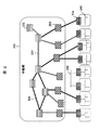
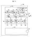
図2は各実施形態の前提となるネットワーク構成図である。各LAN205を代表するGW204が中継網201を介して接続されている。中継網201は、GW203を収容するエッジ装置203と、エッジ装置203間を接続するコア装置202から構成される。GW204とエッジ装置203間はバス型接続208またはPtP接続され、エッジ装置とコア装置あるいはコア装置間はPtP接続206され、一部はPtP接続二重化207される。本発明は、このエッジ装置203とコア装置202間あるいはコア装置202間のPtP接続206、およびPtP接続二重化207に関わるものである。
FIG. 2 is a network configuration diagram as a premise of each embodiment. A
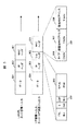
図3は、LAN内、GWとエッジ装置間で使用されるフレームフォーマットと、エッジ装置とコア装置間あるいはコア装置間で使用されるフレームフォーマットを示したものである。シムヘッダ302はエッジ装置で付与または削除するものであり、ラベル305を含む。コア装置では宛先IPアドレスの代わりにこのラベル305を用いて、送信ポートを選択する。なお、図3において、301はMACヘッダ、303はIPヘッダ、304はデータ、306は宛先MACアドレス、307は送信元MACアドレスである。
FIG. 3 shows a frame format used between the GW and the edge device in the LAN, and a frame format used between the edge device and the core device or between the core devices. The
図4は、エッジ装置203、コア装置202の一つの具体的構成を示す図である。装置はIFカード401群、IFカード内の通信ポート402、内部スイッチ403、外部の制御サーバ405と通信し、IFカード401や内部スイッチ403を制御する制御カード404から構成される。IFカード401は処理部として機能する中央処理部(CPU)、各種の表やデータを記憶する記憶部であるメモリ、物理ポート部であるPHY/MACから構成される。このPHYは物理層トランシーバであり、後述するイーサネットフレーム処理が実行され、MACはここではIEEE802.3規格準拠のメディア・アクセス・コントローラである。IFカード401内のCPUは、制御カード404を介して、制御サーバ405からの指示を受け、種々のプログラム処理を実行する。なお、内部スイッチ403も同様に、制御カード404を介して、制御サーバ405によって制御される。
FIG. 4 is a diagram showing one specific configuration of the
図5はエッジ装置において、ラベルスイッチドパスがどのように設定されるかを説明するために、一例を図示したものであり、501がラベルスイッチドパスである。また、エッジ装置203に入力されるデータフレームフォーマットも同時に示している。エッジ装置に入力されるデータフレームには通常のイーサネットフレームとシムヘッダが付加されたMPLS(Multi Protocol Label Switching)フレームの2種類がある。イーサネットフレームが入力された場合、IFカード内でMPLSフレームへ変換され、その後転送処理がなされる。一方、MPLSフレームが入力された場合、そのままMPLSフレームとして転送処理される。
FIG. 5 shows an example for explaining how the label switched path is set in the edge device, and
内部スイッチ403はMPLSフレームのシムヘッダ302中にあるラベル305を参照して出口の通信ポートへ該MPLSフレームを転送する。出口の通信ポートでは接続先の装置によってMPLSフレームのまま送信するか、イーサネットフレームへ変換するか判断し、データフレームを送信する。コア装置202の場合には、入力も出力もMPLSフレームである以外、エッジ装置203と同様である。なお、以下の説明において、ラベルを参照してMPLSフレームを転送する内部スイッチを有する装置を纏めてラベルスイッチ装置と呼ぶ場合がある。
The
図6は図5に示されるエッジ装置とコア装置、あるいはコア装置間でPtP接続二重化構成をとった場合の装置間接続図である。図6ではラベルスイッチ装置A601のIFカードA3,A4とラベルスイッチ装置Z602のIFカードZ1,Z2との間で二本のPtP接続を設定している。通常はラベルスイッチ装置A601のIFカードA3とラベルスイッチ装置Z602のIFカードZ1との間のworking側経路603(実線)で通信を実施しているが、例えば装置間を接続しているケーブルが切れた時などの障害が発生した場合、protection側経路604(点線)へ通信経路を切り替える。この切り替え機能により、障害が発生しても通信を切断せず継続させることができる。以下、一般的な切り替え手順について説明する。 FIG. 6 is an inter-device connection diagram when a dual PtP connection configuration is adopted between the edge device and the core device shown in FIG. 5 or between the core devices. In FIG. 6, two PtP connections are set between the IF cards A3 and A4 of the label switch device A601 and the IF cards Z1 and Z2 of the label switch device Z602. Normally, communication is performed on the working path 603 (solid line) between the IF card A3 of the label switch device A601 and the IF card Z1 of the label switch device Z602. For example, the cable connecting the devices is disconnected. When a failure occurs, for example, the communication path is switched to the protection side path 604 (dotted line). With this switching function, communication can be continued without being disconnected even if a failure occurs. Hereinafter, a general switching procedure will be described.
図6ではIFカードA2からIFカードA3、および、IFカードA4へ2つのラベルスイッチドパスを設定している。IFカードA2へ入力されたデータフレームは内部スイッチへ送られるが、内部スイッチはデータフレームをコピーし、一方をA3,他方をA4へ転送する。IFカードA3、A4は自身がworking側であるか、protection側であるか、図示を省略した制御カードから通知されており、working側は通常のデータフレーム送信処理を行うが、protection側はデータフレームを廃棄する。もしworking側のIFカードA3が障害を検知した場合、即座に制御カードへ障害発生を通知する。制御カードはただちにprotection側のIFカードA4にデータフレーム送信処理を開始するように指示する。制御カードから指示を受けたprotection側のIFカードA4は、それまで廃棄していたデータフレームの送信処理をただちに開始する。この切り替え処理において、実際に障害が発生してからworking側のIFカードA3が障害を検知するまでの時間をt1、working側のIFカードA3が制御カードに障害を通知し、制御カードがprotection側のIFカードA4にデータフレーム送信指示するまでをt2、指示をうけたIFカードA4が実際にデータフレームを通信ポートから送出するまでの時間をt3とすると、切り替え時間t=t1+t2+t3となる。上述したように、イーサネットの場合にはt3の短縮が課題である。 In FIG. 6, two label switched paths are set from IF card A2 to IF card A3 and IF card A4. The data frame input to the IF card A2 is sent to the internal switch. The internal switch copies the data frame and transfers one to A3 and the other to A4. The IF cards A3 and A4 are notified from the control card (not shown) whether they are on the working side or protection side, and the working side performs normal data frame transmission processing, but the protection side performs data frame transmission. Discard. If the working IF card A3 detects a failure, the control card is immediately notified of the failure. The control card immediately instructs the IF card A4 on the protection side to start the data frame transmission process. The protection-side IF card A4 that has received an instruction from the control card immediately starts transmission processing of the data frame that has been discarded. In this switching process, the time from when an actual failure occurs until the working side IF card A3 detects the failure is t1, the working side IF card A3 notifies the control card of the failure, and the control card is on the protection side. If t2 is the time until a data frame transmission instruction is sent to the IF card A4 and t3 is the time until the IF card A4 that has received the instruction actually sends the data frame from the communication port, the switching time is t = t1 + t2 + t3. As described above, in the case of Ethernet, shortening t3 is a problem.
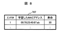
図7はエッジ装置、コア装置における、一般的なIFカードと各通信ポートの論理構成を示す図である。図4に示した通り、IFカード401は装置に複数存在し、一枚のIFカード401内に複数の通信ポート701が存在する。一般的に複数のIFカード間は内部スイッチ403で接続されており、IFカード間をまたがったとしても通信ポート間でデータフレームのやり取りが可能である。ひとつの通信ポート701内では、データフレームの送信処理と受信処理が平行して行われる。図7では左から右への処理が送信処理、右から左への処理が受信処理であり、ポート701内の各ブロックは各ポートに対応する論理機能等を示している。送信ブロック702で受け付けられたデータは、宛先MACアドレス検索機能(部)703でMACアドレス学習表707を用いて検索した宛先MACアドレスと、送信元MACアドレスa708とを、MACヘッダ作成704で付加し、フレーム送信705される。また、受信ブロック709で受け付けられたデータは、フィルタ710でフィルタ処理され、送信元MACアドレス学習機能(部)711でアドレス学習し、その結果をMACアドレス学習表707に反映する。また、出側ポート検索機能(部)712で出側ポート検索表706を用いて出側ポートを検索して、シムヘッダ作成機能(部)713でシムヘッダを作成して、内部スイッチ403に送られる。なお、出側ポート検索表706やMACアドレス学習表707は記憶部であるメモリに記憶される。
FIG. 7 is a diagram showing a logical configuration of a general IF card and each communication port in the edge device and the core device. As shown in FIG. 4, a plurality of
図8はMACアドレス学習表707の例である。各エントリ番号に対応して、学習したMACアドレス欄と寿命欄が設けられ、本表707に登録されてから当該寿命欄の時間が経過したのち、当該MACアドレスは本表から削除される。 FIG. 8 is an example of the MAC address learning table 707. Corresponding to each entry number, a learned MAC address column and a lifetime column are provided, and after the time in the lifetime column has elapsed since registration in this table 707, the MAC address is deleted from the table.
図9は出側ポート検索表706の例である。検索表706の入側情報とは、あるデータフレームを受信したIFカード番号、通信ポート番号と、当該フレームから抽出したラベルを指す。これらを検索キーとして、出側情報を得る。出側情報はデータフレームを送信すべきIFカード番号、通信ポート番号、当該データフレームに付与すべきラベルである。なお、これらの入側情報、出側情報は事前に本表706の各欄に設定されていることを前提とする。通常、中継網を管理するオペレータが手入力で設定する。 FIG. 9 is an example of the outgoing port search table 706. The entry information in the search table 706 indicates the IF card number and communication port number that received a certain data frame, and the label extracted from the frame. Using these as search keys, egress information is obtained. The outgoing side information includes an IF card number to which a data frame is to be transmitted, a communication port number, and a label to be attached to the data frame. It is assumed that the entry side information and the exit side information are set in advance in each column of this table 706. Usually, the operator who manages the relay network sets it manually.
以上、各実施例の前提となるネットワーク構成について説明した。以下、個々の実施例について説明する。 The network configuration that is the premise of each embodiment has been described above. Each example will be described below.
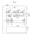
図10は、第一の実施例によるラベルスイッチ装置内のIFカードと通信ポートの構成を示す図である。1000は図6のIFカードA3に対応し、1001はそのポートの論理機能を示す。送信ブロック702にデータフレームが到着すると、MACヘッダ作成、MACアドレスコピー機能(部)1002はMACヘッダ作成、あるいはMACアドレスコピーを行う。従来装置にあっては、図7で説明したように、MACアドレス学習表707から入手したMACアドレスを、MACヘッダ作成機能(部)704で宛先MACアドレス領域へ設定しているが、本実施例ではMACヘッダ作成、MACアドレスコピー機能(部)1002で、データフレームごとにまったくランダムなMACアドレスを設定するか、1つの固定したMACアドレスを設定するか、あるいは受信したデータフレーム中の送信元MACアドレス領域の内容を宛先MACアドレス領域へコピーする。そのために、ランダム/固定MACアドレス機能(部)1003は、ランダムなMACアドレスを生成する機能、または固定MACアドレスを保持する機能を具備している。次に、フレーム送信ブロック705は、送信元MACアドレス領域へ事前に割り当てられた送信元MACアドレスa708を設定し、インターフェースポート714から該当データフレームを送信する。
FIG. 10 is a diagram showing the configuration of the IF card and communication port in the label switch device according to the first embodiment. 1000 corresponds to the IF card A3 in FIG. 6, and 1001 indicates the logical function of the port. When the data frame arrives at the
受信処理においては、インターフェースポート714から受信ブロック709にデータフレームが到着すると、出側ポート検索712において、受信したデータフレームのシムヘッダ領域からラベルが抽出され、これと当該IFカード番号、当該通信ポート番号を検索キーとして、出側ポート検索表706を検索する。シムヘッダ作成機能(部)713では、得られたラベルをデータフレームのシムヘッダ中のラベル領域へ書き込み、同じく検索結果として得られたIFカード番号、通信ポート番号で示される通信ポートへ内部スイッチ経由で送信する。このとき、宛先MACアドレス、送信元MACアドレスへは何の変更もされない。すなわち、本実施例においては、図7に示した構成とは異なり、フィルタリングや送信元MACアドレス学習は行わない。
In the reception process, when a data frame arrives at the reception block 709 from the
先に説明したとおり、従来装置においては、MACアドレスは装置を識別する機能を持ち、宛先MACアドレスと自分のMACアドレスが一致するかどうか調べるフィルタリング処理をフィルタ710で行うことにより、受信したデータフレームが自分宛てのものかどうか判断する。しかし、PtP接続の場合には接続先が一箇所に特定可能なため、受信したデータはすべて自分宛であると仮定することが可能である。したがって受信したデータフレームをフィルタせずに全て受け入れることが可能である。ただし、接続先装置が誤って無関係なデータフレームを送信してしまう可能性があり、その場合受け入れてはいけないデータフレームを受け入れてしまうこととなる。
As described above, in the conventional apparatus, the MAC address has a function of identifying the apparatus, and the
ここで無関係なデータフレームとは、あらかじめ設定されているラベルスイッチドパス以外のデータフレームを指す。すなわち、あらかじめ設定されているラベルスイッチドパスのラベル値以外の値がシムヘッダ内のラベルフィールドに設定されているデータフレームは無関係であり、廃棄すべきデータフレームである。本実施例においては、これら無関係なデータフレームは、出側ポート検索表を検索する際に検索結果が得られないため、出側ポート検索712において廃棄される。したがって、フィルタリング処理で宛先MACアドレスが自分のMACアドレスと一致するかどうか調べずに、受信したデータフレームをすべて受け入れてしまって問題ない。
Here, an irrelevant data frame refers to a data frame other than a preset label switched path. That is, a data frame in which a value other than the label value of the preset label switched path is set in the label field in the shim header is irrelevant and is a data frame to be discarded. In this embodiment, these irrelevant data frames are discarded in the
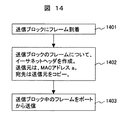
図14は本実施例の構成によるイーサネットフレーム送信処理の手続きの一例を示す図である。本例にあっては、受信したデータフレーム中の送信元MACアドレス領域の内容を宛先MACアドレス領域へコピーする。送信ブロック702にデータフレームが到着する(1401)と、当該フレームのイーサネットヘッダを作成し、送信元MACアドレス領域にMACアドレス708の値aを設定する。次にブロック1002のMACアドレスコピー機能を用いて、送信元MACアドレス領域を宛先MACアドレス領域へコピーする(1402)。最後に当該データフレームをインターフェースポートから送信する(1403)。上記の処理をデータフレームごとに行う。また、送信元MACアドレス領域を宛先MACアドレス領域へコピーするかわりに、ランダム/固定MACアドレス機能1003と共に、あらかじめ設定された固定のMACアドレスや、ランダムに生成したMACアドレスを設定することも可能である。
FIG. 14 is a diagram illustrating an example of a procedure of an Ethernet frame transmission process according to the configuration of the present embodiment. In this example, the contents of the source MAC address area in the received data frame are copied to the destination MAC address area. When a data frame arrives at the transmission block 702 (1401), an Ethernet header of the frame is created, and the value a of the
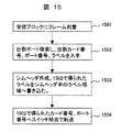
図15は本実施例の構成によるイーサネットフレーム受信処理の手続き図である。受信ブロック709にデータフレームが到着する(1501)と、データフレームのシムヘッダ領域からラベルが抽出され(1502)、これと当該IFカード番号、当該通信ポート番号を検索キーとして、出側ポート検索表706を検索する。得られたラベルをデータフレームのシムヘッダ中のラベル領域へ書き込み(1503)、同じく検索結果得られたIFカード番号、通信ポート番号で示される通信ポートへ内部スイッチ経由で送信する(1504)。このとき、宛先MACアドレス、送信元MACアドレスへは何の変更もされない。 FIG. 15 is a procedure diagram of Ethernet frame reception processing according to the configuration of the present embodiment. When a data frame arrives at the reception block 709 (1501), a label is extracted from the shim header area of the data frame (1502), and the outgoing port search table 706 is used with the IF card number and the communication port number as search keys. Search for. The obtained label is written in the label area in the shim header of the data frame (1503), and transmitted to the communication port indicated by the IF card number and the communication port number obtained similarly from the internal frame via the internal switch (1504). At this time, no change is made to the destination MAC address and the source MAC address.
以上説明した実施例1の効果を説明する。図7の構成にあっては、送信処理においてMACアドレス学習表707を参照していた。PtP接続二重化はデータフレームをやりとりする現用系と、データフレームを一切やりとりしない待機系とで構成される。この待機系においてはデータフレームがやりとりされないため、送信元MACアドレス学習が実行されず、MACアドレス学習表は空となっている。したがって現用系と待機系を切り替える二重化切り替えが起きた直後は、新現用系(旧待機系)のMACアドレス学習表は空となっている。このため、図7の構成においては、受信処理において送信元MACアドレス学習が終了し、MACアドレス学習表に何らかのMACアドレスが登録されるまで、データフレームの送信が遅延する課題があった。この遅延時間は上述したt3に含まれ、本実施例では、送信処理においてMACアドレス学習表を参照しない構成のため、t3を短縮することができる。 The effect of Example 1 demonstrated above is demonstrated. In the configuration of FIG. 7, the MAC address learning table 707 is referred to in the transmission process. Redundant PtP connection is composed of an active system for exchanging data frames and a standby system for exchanging no data frames. Since no data frames are exchanged in this standby system, the source MAC address learning is not executed, and the MAC address learning table is empty. Therefore, immediately after the duplex switching for switching between the active system and the standby system occurs, the MAC address learning table of the new active system (old standby system) is empty. For this reason, in the configuration of FIG. 7, there is a problem that transmission of a data frame is delayed until the transmission source MAC address learning is completed in the reception process and some MAC address is registered in the MAC address learning table. This delay time is included in the above-described t3. In this embodiment, since the MAC address learning table is not referred to in the transmission process, t3 can be shortened.
次にMACアドレス学習表を参照する場合において、上述の課題を解決する第二の実施例を説明する。 Next, a second embodiment for solving the above-described problem when referring to the MAC address learning table will be described.
図11は、第二の実施例によるIFカードと通信ポートの構成を示す図である。送信処理に関して、通常の送信処理に加えて、イーサネット試験フレーム生成機能1102を持つ。本機能は宛先MACアドレスとして、イーサネット規格で定められたブロードキャストMACアドレスを使用し、送信元MACアドレスとして事前に割り当てられたMACアドレスa708を用いたイーサネット試験フレームを生成する。かつ、インターフェースポート714の状態を監視しており、PtP接続先との接続が開始された時に生成したイーサネット試験フレームをインターフェースポート714から送信する機能を持つ。または、PtP接続先との接続が開始された後、切断されるまでの間、周期的に生成したイーサネット試験フレームをインターフェースポート714から送信する機能をもつ。
FIG. 11 is a diagram showing the configuration of an IF card and a communication port according to the second embodiment. With regard to the transmission process, in addition to the normal transmission process, an Ethernet test
この機能は、図4に示したIFカード401内の処理部であるCPUと物理ポート部であるPHY/MACが実行する。すなわち、物理ポート部であるPHY/MACはイーサネットケーブル上を流れる電気信号を監視し、対向装置との電気信号のやり取りが可能になると、「接続開始」となる。逆に対向装置と電気信号のやり取りが不可能になると「切断」となる。このPHY/MACの状態をCPUが周期監視し、PtP接続先との接続が開始を検出してイーサネット試験フレームの送信を行う。
This function is executed by the CPU as the processing unit and the PHY / MAC as the physical port unit in the
上述した本実施例の機能構成により、PtP接続二重化時にデータフレームの送信を行っていない予備系においてもイーサネット試験フレームをやりとりできるため、イーサネット試験フレームの受信処理によって送信元MACアドレス学習が可能となり、MACアドレス学習表1103にMACアドレスを登録可能となる。したがって、二重化切り替え直後においてすでにMACアドレス学習表1103にPtP接続先のMACアドレスが登録されており、本実施例においても、二重化切り替え直後のデータフレームの送信が遅延するという課題が解決される。 With the above-described functional configuration of the present embodiment, an Ethernet test frame can be exchanged even in a standby system that does not transmit a data frame when PtP connection is duplexed. The MAC address can be registered in the MAC address learning table 1103. Therefore, the MAC address of the PtP connection destination is already registered in the MAC address learning table 1103 immediately after the duplex switching, and the problem that the transmission of the data frame immediately after the duplex switching is delayed is also solved in this embodiment.
図12は、図11におけるMACアドレス学習表1103の一例である。MACアドレス学習表1103にはただ1つのみ学習したMACアドレスを設定し、図8のMACアドレス学習表707に存在した寿命欄は存在しない。この学習表1103中のMACアドレスは、二重化接続の切り替え前に学習済みであることは言うまでもない。 FIG. 12 is an example of the MAC address learning table 1103 in FIG. Only one learned MAC address is set in the MAC address learning table 1103, and there is no lifetime column that exists in the MAC address learning table 707 of FIG. Needless to say, the MAC address in the learning table 1103 has been learned before switching the duplex connection.
図13は第三の実施例の通信ポートの構成を示す図である。これは図7の一般的な構成との第一の実施例に構成を組み合わせたポート機能1301である。図13において、実線の矢印で示された処理ルートが図7の構成による処理ルート、二重線の矢印で示された処理ルートが実施例1の構成による処理ルートである。それぞれの処理は図7、図10の説明と同様である。図13の通信ポート構成で追加されたものは、図示を省略した制御サーバから指示を受信するためのスイッチインタフェース1302と、送信ブロック、受信ブロックへ指示を出す検索切り替え機能(部)1303、フィルタ切り替え機能(部)1304である。スイッチインタフェース1302は、制御サーバから与えられた指示を検索切り替え部1303、フィルタ切り替え部1304に通知するものである。検索切り替え部1303は送信ブロック702に対し、バッファ中のデータフレームに対して施すべき処理の切り替え制御を行う。同様に、フィルタ切り替え部1304は受信ブロック709に対し、バッファ中のデータフレームに対して施すべき処理の切り替え制御を行う。制御サーバ装置からの切り替えは、当該通信ポートをバス型接続で用いるか、PtP接続で用いるかによって使い分ける。すなわち、本実施例の構成をとることにより、バス型接続とPtP接続を同一装置で実現可能である。以下、本実施例の切り替え手続きの詳細を図16〜図19で説明する。
FIG. 13 is a diagram showing the configuration of the communication port of the third embodiment. This is a
図16は実施例3の制御サーバからの検索無効設定を実施する場合の手続き図である。制御サーバから検索切り替えの無効が指示されると、スイッチインタフェース1302が当該指示を受信する(1601)。スイッチインタフェース1302は検索切り替え部1303に、無効と設定するように指示する(1602)。指示を受けた検索切り替え部1303は、以後に送信ブロック702に到着したすべてのデータフレームに関して、次の処理としてMACヘッダ作成1002処理を行うように設定する(1603)。
FIG. 16 is a procedure diagram when the search invalidation setting from the control server according to the third embodiment is performed. When invalidation of search switching is instructed from the control server, the
図17は実施例3の制御サーバからの検索有効設定を実施する場合の手続き図である。制御サーバから検索切り替えの有効が指示されると、スイッチインタフェース1302が当該指示を受信する(1701)。スイッチインタフェース1302は検索切り替え部1303に、有効と設定するように指示する(1702)。指示を受けた検索切り替え部1303は、以後に送信ブロックに到着したすべてのデータフレームに関して、次の処理として宛先MACアドレス検索703を行うように設定する(1703)。
FIG. 17 is a procedural diagram in the case where search validity setting is performed from the control server of the third embodiment. If the search server is instructed to enable search switching, the
図18は実施例3の、制御サーバからのフィルタ無効設定を実施する場合の手続き図である。制御サーバからフィルタ切り替えの無効が指示されると、スイッチインタフェース1302が当該指示を受信する(1801)。スイッチインタフェース1302はフィルタ切り替え部1304に、無効と設定するように指示する(1802)。指示を受けたフィルタ切り替え部1304は、以後に受信ブロックに到着したすべてのデータフレームに関して、次の処理として出側ポート検索712を行うように設定する(1803)。
FIG. 18 is a procedural diagram in the case of performing filter invalid setting from the control server according to the third embodiment. When an instruction to disable filter switching is given from the control server, the
図19は実施例3の、制御サーバからのフィルタ有効設定を実施する場合の手続き図である。制御サーバからフィルタ切り替えの有効が指示されると、スイッチインタフェース1302が当該指示を受信する(1901)。スイッチインタフェース1302はフィルタ切り替え部1304に、有効と設定するように指示する(1903)。指示を受けたフィルタ切り替え部1304は、以後に受信ブロックに到着したすべてのデータフレームに関して、次の処理としてフィルタ710を行うように設定する(1903)。
FIG. 19 is a procedural diagram in the case where the filter valid setting is executed from the control server according to the third embodiment. When an instruction to enable filter switching is given from the control server, the
本実施例によれば、制御サーバ装置からの切り替え指示に基づき、通信ポートをバス型接続、或いはPtP接続で用いることができる。 According to the present embodiment, the communication port can be used in a bus type connection or a PtP connection based on a switching instruction from the control server device.
なお、本実施例においては、図7と図10の構成を組み合わせたポート機能を説明したが、これに限定されることなく、例えば図10と図11の構成を組み合わせたポート機能とすることもできる。この場合、図11の構成で、試験フレームを送信し、対向装置から受信したデータフレーム中の送信元MACアドレス領域から抽出できた最初のMACアドレスを、送信じに使用する宛先MACアドレスとして、学習・保持し、図10の構成のポート機能で用いる、固定MACアドレスとして利用することもできる。 In this embodiment, the port function combining the configurations of FIGS. 7 and 10 has been described. However, the present invention is not limited to this, and for example, a port function combining the configurations of FIGS. 10 and 11 may be used. it can. In this case, with the configuration of FIG. 11, the test frame is transmitted, and the first MAC address extracted from the source MAC address area in the data frame received from the opposite device is learned as the destination MAC address used for transmission. It can also be used as a fixed MAC address that is retained and used in the port function configured as shown in FIG.
以上詳述してきた本発明は、ネットワーク通信装置、特にPtP接続でデータ送受信を行うネットワーク通信装置に有効に利用できる。 The present invention described above in detail can be effectively used for a network communication apparatus, particularly a network communication apparatus that performs data transmission / reception through a PtP connection.
301…MACヘッダ
302…シムヘッダ
303…IPヘッダ
304…データ
305…ラベル
306…宛先MACアドレス
307…送信元MACアドレス
401…IFカード
402…通信ポート
403…内部スイッチ
404…制御カード
501…ラベルスイッチドパス。
301 ...
Claims (13)
前記処理部は、受信した前記データフレームを送信する際、前記データフレーム中の前記宛先アドレス領域へ、あらかじめ保持する固定値をコピーして送信するよう制御する、
ことを特徴とするネットワーク装置。 A network communication device that includes a processing unit and transmits / receives a data frame including a source MAC (Media Access Control) address area and a destination MAC address area,
The processing unit controls to copy and transmit a fixed value held in advance to the destination address area in the data frame when transmitting the received data frame.
A network device.
前記処理部は、当該装置自身に設定されたMACアドレスを前記送信元MACアドレス領域に記述した試験フレームを、対向する装置との通信接続が開始されるたび、あるいは周期的に前記対向する装置に送信するよう制御する、
ことを特徴とするネットワーク通信装置。 The network communication device according to claim 1,
The processing unit sends a test frame in which the MAC address set in the device itself is described in the source MAC address area to the facing device every time communication connection with the facing device is started or periodically Control to send,
A network communication device.
前記処理部は、前記試験フレームの送信に応じて受信した、前記試験フレーム中の前記送信元MACアドレス領域から抽出したMACアドレスを、送信時に使用する前記固定値として学習して保持する、
ことを特徴とするネットワーク通信装置。 The network device according to claim 2, wherein
The processing unit learns and holds the MAC address extracted from the transmission source MAC address area in the test frame received in response to the transmission of the test frame as the fixed value used at the time of transmission.
A network communication device.
前記処理部は、受信した前記データフレームを送信する際、前記データフレーム中の前記送信元MACアドレス領域の内容を前記データフレーム中の前記宛先MACアドレス領域へコピーして送信するよう制御する、
ことを特徴とするネットワーク通信装置。 A network communication device that includes a processing unit and transmits / receives a data frame including a source MAC address region and a destination MAC address region,
The processing unit, when transmitting the received data frame, controls to copy and transmit the content of the source MAC address area in the data frame to the destination MAC address area in the data frame,
A network communication device.
前記処理部は、受信した前記データフレームを送信する際、前記データフレーム中の前記宛先MACアドレス領域へランダムな値を設定して送信するよう制御する、
ことを特徴とするネットワーク通信装置。 A network communication device that includes a processing unit and transmits / receives a data frame including a source MAC address region and a destination MAC address region,
The processing unit controls to set and transmit a random value to the destination MAC address region in the data frame when transmitting the received data frame.
A network communication device.
前記IFカードは処理部、記憶部、および物理ポート部を有し、
前記処理部は、前記スイッチから受信した前記データフレームを送信する際、
前記記憶部に記憶するMACアドレス学習表の宛先MACアドレスを検索して、検索した前記宛先MACアドレスを用いてMACヘッダを作成するか、あるいは
受信した前記データフレーム中の前記送信元MACアドレス領域の内容、ランダムな値、又は事前に設定された固定値を、前記宛先アドレス領域にコピーして前記MACヘッダを作成するか、の切り替え制御を行う、
ことを特徴とするネットワーク通信装置。 A network communication apparatus comprising a plurality of interface (IF) cards connected to a switch, and transmitting and receiving a data frame having a source MAC address area and a destination MAC address area,
The IF card has a processing unit, a storage unit, and a physical port unit,
When the processing unit transmits the data frame received from the switch,
Search the destination MAC address of the MAC address learning table stored in the storage unit, create a MAC header using the searched destination MAC address, or the source MAC address area of the received data frame The content, random value, or fixed value set in advance is copied to the destination address area to create the MAC header, or switching control is performed.
A network communication device.
前記処理部は、
前記データフレームを受信した際、
前記送信元MACアドレス領域の前記MACアドレスを学習して前記MACアドレス学習表に保持するか否かの切り替え制御を行う、
ことを特徴とするネットワーク通信装置。 The network communication device according to claim 6,
The processor is
When receiving the data frame,
Switching control whether or not to learn the MAC address of the source MAC address area and hold it in the MAC address learning table;
A network communication device.
前記処理部は、
装置外部からの制御に従い、前記切り替え制御を実行する、
ことを特徴とするネットワーク通信装置。 The network communication device according to claim 6,
The processor is
The switching control is executed according to control from outside the device.
A network communication device.
前記処理部は、
装置外部からの制御に従い、前記MACアドレス学習表に保持するか否かの前記切り替え制御を実行する、
ことを特徴とするネットワーク通信装置。 The network communication device according to claim 7,
The processor is
In accordance with control from the outside of the device, the switching control as to whether or not to hold in the MAC address learning table is executed.
A network communication device.
前記処理部は、
あらかじめ装置自身に設定されたMACアドレスを、前記データフレームの前記送信元MACアドレス領域に記述して送信するよう制御する、
ことを特徴とするネットワーク通信装置。 The network communication device according to claim 6,
The processor is
Control to transmit a MAC address set in advance in the device itself in the source MAC address area of the data frame,
A network communication device.
前記処理部は、
前記データフレームを受信した際、
受信した前記データフレームの前記宛先MACアドレス領域内の前記MACアドレスと、あらかじめ自身に設定されたMACアドレスとを比較した結果に基づき、前記送信元MACアドレス領域の前記MACアドレスを学習して前記MACアドレス学習表に保持するか否かを決定する、
ことを特徴とするネットワーク通信装置。 The network communication device according to claim 7,
The processor is
When receiving the data frame,
Based on a result of comparing the MAC address in the destination MAC address area of the received data frame with a MAC address set in advance in the data frame, the MAC address in the source MAC address area is learned and the MAC address Decide whether to keep in the address learning table,
A network communication device.
前記処理部は、当該装置自身に設定されたMACアドレスを前記送信元MACアドレス領域に記述した試験フレームを対向する装置に送信し、前記対向する装置から受信したデータフレーム中の前記送信元MACアドレス領域から抽出できた最初のMACアドレスを、送信時に使用する宛先MACアドレスとして保持する、
ことを特徴とするネットワーク通信装置。 The network communication device according to claim 7,
The processing unit transmits a test frame in which the MAC address set in the device itself is described in the source MAC address area to the opposite device, and the source MAC address in the data frame received from the opposite device Hold the first MAC address that can be extracted from the area as the destination MAC address to be used at the time of transmission,
A network communication device.
前記IFカードによる前記対向する装置との間の接続がポイントツーポイント(PtP)接続である、
ことを特徴とするネットワーク通信装置。 The network communication device according to claim 12, wherein
The connection between the opposing devices by the IF card is a point-to-point (PtP) connection,
A network communication device.
Priority Applications (4)
| Application Number | Priority Date | Filing Date | Title |
|---|---|---|---|
| JP2009015257A JP2010177752A (en) | 2009-01-27 | 2009-01-27 | Network communication node |
| US12/693,534 US20100189114A1 (en) | 2009-01-27 | 2010-01-26 | Network communication node |
| CN201010105267A CN101789972A (en) | 2009-01-27 | 2010-01-26 | Network communication node |
| EP20100000833 EP2211509A3 (en) | 2009-01-27 | 2010-01-27 | Network communication node |
Applications Claiming Priority (1)
| Application Number | Priority Date | Filing Date | Title |
|---|---|---|---|
| JP2009015257A JP2010177752A (en) | 2009-01-27 | 2009-01-27 | Network communication node |
Publications (2)
| Publication Number | Publication Date |
|---|---|
| JP2010177752A true JP2010177752A (en) | 2010-08-12 |
| JP2010177752A5 JP2010177752A5 (en) | 2011-08-11 |
Family
ID=42078048
Family Applications (1)
| Application Number | Title | Priority Date | Filing Date |
|---|---|---|---|
| JP2009015257A Ceased JP2010177752A (en) | 2009-01-27 | 2009-01-27 | Network communication node |
Country Status (4)
| Country | Link |
|---|---|
| US (1) | US20100189114A1 (en) |
| EP (1) | EP2211509A3 (en) |
| JP (1) | JP2010177752A (en) |
| CN (1) | CN101789972A (en) |
Cited By (1)
| Publication number | Priority date | Publication date | Assignee | Title |
|---|---|---|---|---|
| CN105471836A (en) * | 2014-09-29 | 2016-04-06 | 株式会社日立制作所 | Unidirectional relay device |
Families Citing this family (7)
| Publication number | Priority date | Publication date | Assignee | Title |
|---|---|---|---|---|
| US8059526B2 (en) * | 2009-03-23 | 2011-11-15 | Lsi Corporation | N+1 protection using a processor-based protection device |
| EP2636183A4 (en) * | 2010-11-01 | 2016-08-31 | Hewlett Packard Entpr Dev Lp | Managing mac moves with secure port groups |
| EP2530881B1 (en) * | 2011-06-27 | 2014-02-12 | Huawei Technologies Co., Ltd. | Media access control address protection method and switch |
| TWI481242B (en) * | 2011-08-15 | 2015-04-11 | Mediatek Inc | Method of processing management frame and related communication device |
| US9819596B2 (en) * | 2015-02-24 | 2017-11-14 | Qualcomm Incorporated | Efficient policy enforcement using network tokens for services C-plane approach |
| CN107241249B (en) * | 2017-05-19 | 2020-05-22 | 闫晓峰 | Ethernet bus switch, Ethernet bus system and data communication method |
| CN109327407B (en) * | 2018-08-08 | 2019-12-06 | 广东高云半导体科技股份有限公司 | data exchange device, data exchange method, computer device, and storage medium |
Citations (4)
| Publication number | Priority date | Publication date | Assignee | Title |
|---|---|---|---|---|
| JP2005175591A (en) * | 2003-12-08 | 2005-06-30 | Hitachi Cable Ltd | Switching hub |
| JP2006025121A (en) * | 2004-07-07 | 2006-01-26 | Fujitsu Ltd | Frame transfer method and device therefor |
| JP2006295550A (en) * | 2005-04-11 | 2006-10-26 | Mitsubishi Electric Corp | Packet transfer apparatus |
| JP2008067085A (en) * | 2006-09-07 | 2008-03-21 | Hitachi Communication Technologies Ltd | Packet transfer device |
Family Cites Families (9)
| Publication number | Priority date | Publication date | Assignee | Title |
|---|---|---|---|---|
| US6779039B1 (en) * | 2000-03-31 | 2004-08-17 | Avaya Technology Corp. | System and method for routing message traffic using a cluster of routers sharing a single logical IP address distinct from unique IP addresses of the routers |
| JP3868815B2 (en) * | 2002-01-10 | 2007-01-17 | 富士通株式会社 | Communications system |
| JP4023281B2 (en) * | 2002-10-11 | 2007-12-19 | 株式会社日立製作所 | Packet communication apparatus and packet switch |
| WO2005109718A1 (en) * | 2004-05-05 | 2005-11-17 | Gigamon Systems Llc | Asymmetric packet switch and a method of use |
| US7486610B1 (en) * | 2005-05-11 | 2009-02-03 | Cisco Technology, Inc. | Multiple virtual router group optimization |
| US8498297B2 (en) * | 2005-08-26 | 2013-07-30 | Rockstar Consortium Us Lp | Forwarding table minimisation in ethernet switches |
| JP4347335B2 (en) * | 2006-12-18 | 2009-10-21 | 富士通株式会社 | Network relay program, network relay device, communication system, and network relay method |
| JP4773981B2 (en) * | 2007-01-12 | 2011-09-14 | 富士通株式会社 | Communication control program |
| US8077720B2 (en) * | 2007-02-27 | 2011-12-13 | Alcatel-Lucent Usa Inc. | Methods and devices for generating and forwarding translated MAC addresses |
-
2009
- 2009-01-27 JP JP2009015257A patent/JP2010177752A/en not_active Ceased
-
2010
- 2010-01-26 US US12/693,534 patent/US20100189114A1/en not_active Abandoned
- 2010-01-26 CN CN201010105267A patent/CN101789972A/en active Pending
- 2010-01-27 EP EP20100000833 patent/EP2211509A3/en not_active Withdrawn
Patent Citations (4)
| Publication number | Priority date | Publication date | Assignee | Title |
|---|---|---|---|---|
| JP2005175591A (en) * | 2003-12-08 | 2005-06-30 | Hitachi Cable Ltd | Switching hub |
| JP2006025121A (en) * | 2004-07-07 | 2006-01-26 | Fujitsu Ltd | Frame transfer method and device therefor |
| JP2006295550A (en) * | 2005-04-11 | 2006-10-26 | Mitsubishi Electric Corp | Packet transfer apparatus |
| JP2008067085A (en) * | 2006-09-07 | 2008-03-21 | Hitachi Communication Technologies Ltd | Packet transfer device |
Cited By (2)
| Publication number | Priority date | Publication date | Assignee | Title |
|---|---|---|---|---|
| CN105471836A (en) * | 2014-09-29 | 2016-04-06 | 株式会社日立制作所 | Unidirectional relay device |
| CN105471836B (en) * | 2014-09-29 | 2019-03-22 | 株式会社日立制作所 | One-way junction device |
Also Published As
| Publication number | Publication date |
|---|---|
| US20100189114A1 (en) | 2010-07-29 |
| EP2211509A3 (en) | 2010-08-18 |
| CN101789972A (en) | 2010-07-28 |
| EP2211509A2 (en) | 2010-07-28 |
Similar Documents
| Publication | Publication Date | Title |
|---|---|---|
| JP2010177752A (en) | Network communication node | |
| US6870840B1 (en) | Distributed source learning for data communication switch | |
| JP4747118B2 (en) | Router, communication guarantee method and communication guarantee program | |
| JP5885747B2 (en) | System and method for providing scalability of Ethernet over InfiniBand virtual hub in a middleware machine environment | |
| JP5594552B2 (en) | Network system and route control method | |
| JP4587446B2 (en) | NETWORK SYSTEM, SWITCH DEVICE, ROUTE MANAGEMENT SERVER, ITS CONTROL METHOD, COMPUTER PROGRAM, AND COMPUTER-READABLE STORAGE MEDIUM | |
| CN101150527B (en) | A PCIE data transmission method, system and device | |
| US20060256801A1 (en) | Gateway system | |
| US20050265230A1 (en) | Apparatus and method for performing state transition of backup router in router redundancy system | |
| EP1773008A1 (en) | Method and system for implementing virtual router redundancy protocol on a resilient packet ring | |
| JPH11112577A (en) | Interconnection system between lan systems and network service system | |
| JP5612468B2 (en) | Method and apparatus for communication of diagnostic data in a real-time communication network | |
| CN102420762B (en) | Message forwarding method, message forwarding system, network equipment and firewall wire card | |
| JP2010531602A5 (en) | ||
| JP2015211374A (en) | Information processing system, control method for information processing system, and control program for management device | |
| JP2007208502A (en) | Communication system, backup router, redundant processing program thereof, and redundant processing method thereof | |
| JP2010239591A (en) | Network system, relay device, and method of controlling network | |
| JP2008022271A (en) | Network apparatus | |
| WO2009146615A1 (en) | A processing method, a system and a processor for network address translation service | |
| JP2009147695A (en) | Method of controlling communication, and system | |
| US20060098665A1 (en) | Systems and methods for communicating with bi-nodal network elements | |
| JP5251716B2 (en) | Packet relay device | |
| CN101127770B (en) | Backup method based on address parsing protocol proxy | |
| WO2014162331A1 (en) | Bridge, network system, air-conditioner outdoor unit, and air-conditioning network system | |
| US20210314182A1 (en) | Multicast routing in a logical router having separated north/south and east/west packet handlers |
Legal Events
| Date | Code | Title | Description |
|---|---|---|---|
| A521 | Request for written amendment filed |
Free format text: JAPANESE INTERMEDIATE CODE: A523 Effective date: 20110624 |
|
| A621 | Written request for application examination |
Free format text: JAPANESE INTERMEDIATE CODE: A621 Effective date: 20110624 |
|
| A977 | Report on retrieval |
Free format text: JAPANESE INTERMEDIATE CODE: A971007 Effective date: 20120820 |
|
| A131 | Notification of reasons for refusal |
Free format text: JAPANESE INTERMEDIATE CODE: A131 Effective date: 20120828 |
|
| A521 | Request for written amendment filed |
Free format text: JAPANESE INTERMEDIATE CODE: A523 Effective date: 20121026 |
|
| A01 | Written decision to grant a patent or to grant a registration (utility model) |
Free format text: JAPANESE INTERMEDIATE CODE: A01 Effective date: 20130226 |
|
| A045 | Written measure of dismissal of application [lapsed due to lack of payment] |
Free format text: JAPANESE INTERMEDIATE CODE: A045 Effective date: 20130625 |