The specific embodiment
Based on description of drawings one embodiment of the invention.Housing 1 is as shown in Figure 1, is made up of outer container 2, interior case 3 and heat-barrier material 4.Outer container 2 and interior case 3 form the rectangle of the lengthwise of front surface opening respectively, have base plate, left plate, right plate, top board and back plate.Each of the base plate of this outer container 2~back plate is made up of steel plate, and each of the base plate of interior case 3~back plate is made up of synthetic resin.Should in case 3 be accommodated in the inside of outer container 2 from the place ahead, the base plate of the base plate of outer container 2 and interior case 3 each other at above-below direction across the gap and mutually opposed, the left plate of outer container 2 and interior case 3
A left sideSide plate each other at left and right directions across the gap and mutually opposed; The right plate of the right plate of outer container 2 and interior case 3 each other at left and right directions across the gap and mutually opposed; The top board of the top board of outer container 2 and interior case 3 each other at above-below direction across the gap and mutually opposed, the back plate of outer container 2 and the back plate of interior case 3 each other at fore-and-aft direction across the gap and mutually opposed.
As shown in Figure 2, on the base plate of outer container 2, be formed with bottom flange portion 5, on the left plate of outer container 2, be formed with left flange part 6, on the right plate of outer container 2, be formed with right flange part 7, on the top board of outer container 2, be formed with the top flange part.The mutual gap of base plate of the base plate of bottom flange portion 5 locking outer container 2 and interior case 3 from the place ahead; The left plate of left side flange part 6 locking outer container 2 and the mutual gap of left plate of interior case 3 from the place ahead; The right plate of right flange part 7 locking outer container 2 and the mutual gap of right plate of interior case 3 from the place ahead; The mutual gap of top board of the top board of top flange part locking outer container 2 from the place ahead and interior case 3, heat-barrier material 4 are filled in the mutual gap of two base plates~mutual gap of plate, two backs respectively.
In the inside of housing 1, as shown in Figure 1, be fixed with the heat insulation spaced walls 8 of level.This heat insulation spaced walls 8 is made up of the heat-barrier material of in the box of hollow form, taking in solid shape such as foamed styrene, and in the inside of housing 1, refrigerating chamber 9 is positioned at and is formed at the top of heat insulation spaced walls 8.This refrigerating chamber 9 is spatial portions of front surface opening, and is as shown in Figure 2 in housing 1, and left-hand door 10 is positioned at and is installed in the place ahead of refrigerating chamber 9 with each of right door 11.Left-hand door 10 can be that rotate at the center with vertical axle 12 at the blocking of the left side in the front surface of locking refrigerating chamber 9 and the open mode of opening the left side each other, and right door 11 can be the center rotation with vertical axle 13 at the blocking of the right-hand part in the front surface of locking refrigerating chamber 9 and the open mode of opening right-hand part each other.
As shown in Figure 1, in the inside of housing 1, cold air path 14 is positioned at and is fixed in the rearward end of refrigerating chamber 9.This cold air path 14 points to above-below direction, forms the cold air inlet in the bottom of cold air path 14, forms cold air outlet 15 in the upper end.Taken in fan assembly 16 in the inside of this cold air path 14.This fan assembly 16 constitutes through the rotating shaft that fan is linked to fan motor; Under the state of left-hand door 10 and right door 11 difference lockings; When making the fan motor running, through the rotation of fan, the air in the refrigerating chamber 9 attracted in the cold air path 14 from the cold air inlet of cold air path 14; After in cold air path 14, rising, spue refrigerating chamber 9 from cold air outlet 15 in.
As shown in Figure 1, in housing 1, Machine Room 17 is positioned at and is formed at rearward end.This Machine Room 17 is positioned at the bottom of housing 1, in Machine Room 17, takes in the compressor 18 of freeze cycle.Refrigeration is connected with this compressor 18 with evaporimeter 19, carries refrigerant to refrigeration with evaporimeter 19 from compressor 18.This refrigeration is accommodated in evaporimeter 19 in the cold air path 14 of refrigerating chamber 9, through making through the cooling of the air in the cold air path 14, cold air is circulated in refrigerating chamber 9, and the temperature in the refrigerating chamber 9 is controlled at the temperature province that is used for stored refrigerated food.
As shown in Figure 1, in the inside of housing 1, refrigerating chamber 20 is formed at the below of heat insulation spaced walls 8.This refrigerating chamber 20 is spaces of front surface opening, and is as shown in Figure 3 in housing 1, and the header board 21 of steel plate system is fixed on the leading section of refrigerating chamber 20.This header board 21 has vertical last contact-making surface 22 that points to left and right directions and the vertical following contact-making surface 23 that points to left and right directions; As shown in Figure 2, divide the following refrigerating chamber 24 of the below that header board 21 is arranged, the upper left ice-making compartment 25 of header board 21, the top-right refrigerating chamber 26 of going up of header board 21 in the refrigerating chamber 20.This time refrigerating chamber 24 is equivalent to storeroom.
As shown in Figure 3, on the back surface of header board 21, be fixed with the plastic preceding frame 27 that points to left and right directions.Should before frame 27 form the cross section コ word shape of front surface openings, the front surface of preceding frame 27 through header board 21 from the place ahead by locking.On the base plate of this preceding frame 27, be formed with the tabular rib 28 of the level of pointing to left and right directions.On this rib 28, square tube is crossed header board 21 and is screwed togather a plurality of screws 29 in the past, and preceding frame 27 engages with header board 21 through the fastening force of a plurality of screws 29.
As shown in Figure 2, on housing 1, left sliding door 30 is installed in the place ahead of ice-making compartment 25.This left side sliding door 30 can move towards the fore-and-aft direction straight line with the open mode of opening the front surface of ice-making compartment 25 at the blocking of the front surface of locking ice-making compartment 25 each other, and is as shown in Figure 1 on left sliding door 30, is supported with ice chest 31.This ice chest 31 is accommodated in the ice-making compartment 25 under the blocking of left sliding door 30; Under the open mode of left sliding door 30, in ice-making compartment 25, forwards pull out; Under the blocking of left sliding door 30, ice drops in the ice chest 31 from the ice machine in the ice-making compartment 25 automatically.
As shown in Figure 2, in housing 1, right sliding door 32 is installed in the place ahead of last refrigerating chamber 26.This right side sliding door 32 can move towards the fore-and-aft direction straight line with the open mode of opening the front surface of refrigerating chamber 26 at the blocking of the front surface of refrigerating chamber in the locking 26 each other, at right sliding door 32 upper supports refrigerated container is arranged.This refrigerated container input is useful on the food of freezing preservation, and under the blocking of right sliding door 32, is accommodated in the refrigerating chamber 26, under the open mode of right sliding door 32, in last refrigerating chamber 26, forwards pulls out.
As shown in Figure 4, on each of the left plate of interior case 3 and right plate, following slot part 33 is positioned at and is formed at down refrigerating chamber 24.Each of these two following slot parts 33 pointed to fore-and-aft direction point-blank, is fixed with trapped orbit in each of twice slot parts 33.Each of these two trapped orbits pointed to fore-and-aft direction point-blank along following slot part 33; As shown in Figure 2; On each of two trapped orbits; The 1st movable track 34 that direction forwards, backwards moves is installed, the 2nd movable track 35 that direction forwards, backwards moves is installed on each of two the 1st movable tracks 34.Each of these two the 1st movable tracks 34 and two the 2nd movable tracks 35 pointed to fore-and-aft direction point-blank, is fixed with common lower slider door 36 at the leading section separately of two the 2nd movable tracks 35.This lower slider door 36 is equivalent to door, and two the 2nd movable tracks 35 link via lower slider door 36 each other.
As shown in Figure 2; Lower slider door 36 forms the rectangle of growing crosswise; Move along the 1st movable track 34 under the inactive state of the 1st movable track 34 through each of two the 2nd movable tracks 35; The change in location of fore-and-aft direction moves the change in location of fore-and-aft direction through each of two the 1st movable tracks 34 along trapped orbit under the inactive state of the 2nd movable track 35.Promptly; Lower slider door 36 can; Each of two the 1st movable tracks 34 and two the 2nd movable tracks 35 be operated to the such locked position of coupler in the Limitation Of Movement position at rear and two the 1st movable tracks 34 and two the 2nd movable tracks 35 each to be operated to the such open position in the Limitation Of Movement position in the place ahead mutual, the direction straight line moves forwards, backwards.
On the back plate of interior case 3, as shown in Figure 4, electromagnet 37 is positioned at and is fixed on each of twice slot parts 33, and is fixed with from the place ahead and electromagnet 37 opposed vertical magnetic sheets in the rearward end separately of two the 1st movable tracks 34.Each of these two electromagnet 37 coiling coil on iron core forms; Under situation with 36 the past of lower slider door backward operation; In the magnetic field of the electromagnet 37 at the magnetic sheet entering rear separately of two the 1st movable tracks 34; Thus, magnetic attraction acts on the magnetic sheet in the place ahead from each of two electromagnet 37, and lower slider door 36 is drawn in locked position of coupler by magnetic attraction.That is, each is organized magnetic sheet and electromagnet 37 and constitutes the feed mechanism of lower slider door 36 being drawn in locked position of coupler.
As shown in Figure 3, lower slider door 36 is filled into through the polyurathamc 39 that will be equivalent to heat-barrier material in the door box 38 of hollow form and constitutes.This box 38 has top board, base plate, header board, back plate, left plate and right plate, and through plate 40 in front of the door, behind the door plate 41, on cover 42 and down cover 43 (with reference to Fig. 2) be bonded with each other and constitute.Plate 40 is a material with the steel plate in front of the door, and become upper surface, lower surface and surface, back each be the コ word frame shape of opening.Behind the door plate 41, on cover 42 and down each of cover 43 be material with synthetic resin; The back surface of plate 40 is through plate 41 lockings behind the door in front of the door; As shown in Figure 2, in front of the door plate 40 and behind the door the mutual gap of plate 41 through the locking of last cover 42, and through cover 43 lockings down from the below from the top.As shown in Figure 5, on the plate behind the door 41 of this lower slider door 36, vertical installed surface 44 is positioned at and is formed on peripheral part.This installed surface 44 forms and surrounds four square ring shapes of plate 41 behind the door, on installed surface 44, forms slot part 44a.The back surface opening of this slot part 44a, and be formed at the whole zone of installed surface 44 with the mode of surrounding lower slider door 36.
As shown in Figure 5, on lower slider door 36, be fixed with the liner 45 of rubber system.This liner 45 has the installation portion 47 of liner main body 46 with the ring-type of surrounding lower slider door 36 of the ring-type of surrounding lower slider door 36, through being fixed in the installed surface 44 of lower slider door 36 in the slot part 44a that installation portion 47 is pressed into plate 41 behind the door.The liner main body 46 of this liner 45 forms hollow form, is formed with spaced walls 48 in the inside of liner main body 46.This spaced walls 48 is spaced apart liner main body 46 the interior sealing 50 of outer seal portion 49 and interior all sides of outer circumferential side; Be still at lower slider door 36 under the state of locked position of coupler; The top portion of outer seal portion 49 is flexibly flattened at the following contact-making surface 23 of plate behind the door 41 and preceding frame 21 each other; The left lateral of outer seal portion 49 is flexibly flattened at the left flange part 6 of plate behind the door 41 and outer container 2 each other; The right portion of outer seal portion 49 is flexibly flattened at the right flange part 7 of plate behind the door 41 and outer container 2 each other; The following portion of outer seal portion 49 is flexibly flattened in the bottom flange portion 5 of plate behind the door 41 and outer container 2 each other, and thus, lower slider door 36 is sealed as airtight conditions each other with refrigerating chamber 24.
As shown in Figure 5, in the outer seal portion 49 of liner 45, taken in locking magnet 51.This locking magnet 51 forms the ring-type of surrounding lower slider door 36; Lower slider door 36 is through on the magnetic force basis separately of two electromagnet 37; Be adsorbed on magnetic force by locking magnet 51 on each of following contact-making surface 23 of right flange part 7 and preceding frame 21 of left flange part 6, outer container 2 of bottom flange portion 5, the outer container 2 of outer container 2, and be maintained at locked position of coupler.On the plate behind the door 41 of this lower slider door 36, be formed with rope form reinforcing steel 52.This rope form reinforcing steel 52 forms and surrounds the ring-type of plate 41 behind the door, and is configured in the interior perimembranous of liner 45.It is rearward outstanding that this rope form reinforcing steel 52 is compared the installed surface 44 of plate 41 behind the door; Be still in the elastic deformation amount of the outer seal portion 49 of the liner 45 under the state of locked position of coupler at lower slider door 36, set so that each of outer seal portion 49 and interior sealing 50 compared the rearward outstanding mode in back surface of rope form reinforcing steel 52.The Δ H of Fig. 5 representes that lower slider door 36 is still in outer seal portion 49 and each overhang with respect to the back surface of rope form reinforcing steel 52 of interior sealing 50 under the state of locked position of coupler.
As shown in Figure 1, on each of two the 2nd movable tracks 35 of lower slider door 36, common following refrigerated container 53 is installed.This time refrigerated container 53 is containers of upper surface open, in following refrigerated container 53, is used for the food of freezing preservation through upper surface discrepancy.On this time refrigerated container 53, the middle refrigerated container 54 of upper surface open is installed.Each of this time refrigerated container 53 and middle refrigerated container 54 and lower slider door 36 move integratedly; Be accommodated in down in the refrigerating chamber 24 through lower slider door 36 being operated locked position of coupler; Lower slider door 36 is being operated under the state of open position, from forwards pulling out in the refrigerating chamber 24 down.
As shown in Figure 4, on each of the left plate of interior case 3 and right plate, last slot part 33A is positioned at and is formed on the top of twice slot parts 33.These two go up slot part 33A each point to fore-and-aft direction point-blank, on two, insert horizontal flanges in each of slot part 33A.This flange is as shown in Figure 1; Be formed at the last refrigerated container 55 of upper surface open; Last refrigerated container 55 is directed through flange inner surface separately of slot part 33A on two; And with following refrigerated container 53 and middle refrigerated container 54 each respectively, and with lower slider door 36 mutually independently forwards, backwards direction move.Should go up refrigerating chamber 55 and be disposed at down in the refrigerating chamber 24, in refrigerating chamber 24 down, it is 3 layers that following refrigerated container 53, middle refrigerated container 54 and last refrigerated container 55 are taken at above-below direction.
As shown in Figure 1, in the inside of housing 1, back cold air path 56 is positioned at and is fixed in the rearward end of refrigerating chamber 24.This back cold air path 56 forms the path shape that points to above-below direction, and in the cold air path 56 of back, cold air inlet 57 is positioned at and is formed at the bottom, and cold air outlet is positioned at and is formed at the upper end.In this back cold air path 56, taken in fan assembly 58.This fan assembly 58 is linked to fan on the rotating shaft of fan motor; Under each blocking of left sliding door 30, right sliding door 32 and lower slider door 36; When fan motor turned round, through fan rotation, the air in the following refrigerating chamber 24, the air in the ice-making compartment 25 and the air in the refrigerating chamber 26 every kind attracted in the cold air path 56 of back from cold air inlet 57; After in the cold air path 56 of back, rising, discharge from cold air outlet.
As shown in Figure 1, in the inside of housing 1, preceding cold air path 59 is positioned at and is fixed in the place ahead of back cold air path 56.Should form the path shape that points to above-below direction by preceding cold air path 59, the upper end of preceding cold air path 59 is connected in the cold air outlet of the upper end of back cold air path 56.In this preceding cold air path 59; Be formed with in the ice-making compartment of ice-making compartment 25 inner openings outlet 60, refrigerating chamber outlet on last refrigerating chamber 26 inner openings, towards following refrigerated container outlet 61 (with reference to Fig. 4) of refrigerating chamber 53 openings down, export 63 (with reference to Fig. 1) towards middle refrigerated container outlet 62 (with reference to Fig. 1) of middle refrigerated container 54 openings and towards the last refrigerated container of last refrigerated container 55 openings; The air of discharging from the cold air outlet of back cold air path 56 before entering in the cold air path 59 after; Be discharged in the ice-making compartment 25 from ice-making compartment outlet 60; Be discharged in the refrigerating chamber 26 from last exported frozen; Following refrigerated containers 53 in from following refrigerated container outlet 61 towards following refrigerating chamber 24 are discharged; Therefrom refrigerated container outlet 62 is discharged towards the middle refrigerated containers 54 in the refrigerating chamber 24 down, last refrigerated containers 55 discharges in from last refrigerated container outlet 63 towards refrigerating chamber 24 down.Should go up refrigerated container outlet 63 form from after the quadrangular barrel shape that diminishes of the width dimensions of above-below direction onwards, export 63 leading section at last refrigerated container, as shown in Figure 4, be formed with the contact-making surface 64 of level.
As shown in Figure 1, in the back cold air path 56 of refrigerating chamber 24, be fixed with the freezing of freeze cycle with evaporimeter 65.This freezing with evaporimeter 65 from the Machine Room compressors in 17 18 supply with refrigerants; And through cooling off through the air in the back cold air path 56; Thereby make cold air ice-making compartment 25, on refrigerating chamber 26 and circulating in each of refrigerating chamber 24 down; With the temperature in the refrigerating chamber 24 and go up temperature in the refrigerating chamber 26 each be controlled at the temperature province that can carry out freezing preservation to food, and can the temperature in the ice-making compartment 25 be controlled at can ice making temperature province.
As shown in Figure 3, on cover 42 on the lower slider door 36, vertical tabular handle portion 66 is positioned at and is formed on leading section.As shown in Figure 2, this handle portion 66 is formed on the whole zone of the left and right directions of cover 42, and on the plate in front of the door 40 of lower slider door 36, recess 43 is positioned at and is formed at the rear of handle portion 66.The remainder of removing outside the recess 43 in this recess 43 and the plate 40 is in front of the door compared depression rearward, is formed on the remainder outside each of removing left part and right part in the plate 40 in front of the door.As shown in Figure 3, this recess 43 be formed on the handle portion 66 from below tangle the spatial portion 67 of finger, through through spatial portion 67 finger being hung on the handle portion 66 from the below, thus backward operation lower slider door 36 in the past.
As shown in Figure 6, on cover and be formed with mechanism chamber 68 on 42.The upper surface of this mechanism chamber 68 and back surface be opening respectively, and the bottom surface of mechanism chamber 68 is as shown in Figure 5, is set at first half and is configured in step-like than latter half of low position.This mechanism chamber 68 with respect to the centreline configuration of the left and right directions of lower slider door 36 in the part of the side of taking back, as shown in Figure 7, in mechanism chamber 68, be fixed with the door magnet 69 that constitutes by permanent magnet.This magnet 69 is configured in the left back bight in the mechanism chamber 68, and in the preceding frame 27 of housing 1, door switch 70 is positioned at and is accommodated in the rear of a magnet 69.This door switch 70 is made up of the Hall integrated circuit non-contact switch such as (Hall IC) that switches electric state through magnetic force, is still at lower slider door 36 under the state of lock position, in the surveyed area of door magnet 69 access door switches 70; Thus; Door switch 70 is by electrically conducting, and when locked position of coupler was operated to the rest position in the place ahead, door magnet 69 was retreated in the surveyed area of door switch 70 at lower slider door 36; Thus, door switch 70 is ended by electric.The rest position of this lower slider door 36 is set in the rear of open position; Instantly sliding door 36 from locked position of coupler forwards by when operation; Before lower slider door 36 arrived open position from locked position of coupler, door switch 70 switched to electric cut-off state from the electrically conducting state.
As shown in Figure 7, in mechanism chamber 68, taken in left arm 71.This left arm 71 points to left and right directions, is inserted with the left side axle 72 that points to above-below direction in the left part of left arm 71.This left side axle 72 is fixed in the base plate of mechanism chamber 68, and left arm 71 can be that the center is accommodated in the mechanism chamber 68 rotationally with left side axle 72.In this mechanism chamber 68, taken in right arm 73.This right arm 73 points to left and right directions, is inserted with the right axle 74 that points to above-below direction in the right part of right arm 73.This right side axle 74 is fixed in the base plate of mechanism chamber 68, and right arm 73 can be that the center is accommodated in the mechanism chamber 68 rotationally with right axle 74.Be inserted with the axis 75 that points to above-below direction on this right arm 73.The right part that this axis 75 inserts left arm 71, left arm 71 can link via axis 75 with right arm 73 each other rotationally.This left side axle 72 is configured on the common straight line that points to left and right directions with right axle 74, and it is identical with the mutual distance of right 74 and axis 75 that left side axle 72 and axis 75 mutual distances are set at.This left arm 71 constitutes link mechanisms with right arm 73, and each of left arm 71 and right arm 73 is equivalent to the composed component of link mechanism, promptly, joint.
On last cover 42, as shown in Figure 7, the axle 76 of points upwards is positioned at and is fixed in the base plate of mechanism chamber 68, on the outer peripheral face of axle 76, is inserted with the coil portion of backspring 77.This backspring 77 is made up of torsion spring, has coil portion, arm and the short arm of size that size is long.On last cover 42, the spring travel limitor 78 of prominent shape is positioned at and is fixed in the base plate of mechanism chamber 68, and the short arm of the size of backspring 77 contacts with spring travel limitor 78.The arm that the size of this backspring 77 is long contacts with the back surface of right arm 73, and right arm 73 is suppressed to the counter clockwise direction of Fig. 7 by the spring force of backspring 77, and left arm 71 is suppressed by the clockwise direction of the spring force of backspring 77 to Fig. 7.
On last cover 42, as shown in Figure 7, columned protuberance is formed at the place ahead of axis 75.This protuberance is formed at the base plate of mechanism chamber 68, on the outer peripheral face of protuberance, is fixed with limiter 79 cylindraceous.This limiter 79 constitutes by comparing padded coamings such as all soft rubber or silicon with each of left arm 71 and right arm 73; Through right arm 73 by the elastic force pressure of backspring 77 and contact with limiter 79; Thus, each of left arm 71 and right arm 73 remains on mutually on the rest position of linearity each other.Be formed with motion arm 80 on this right arm 73.This motion arm 80 is to remain under the state of rest position in each of left arm 71 and right arm 73, and the part arranged side by side abreast with respect to left arm 71 at the rear of left arm 71 on motion arm 80, is fixed with to the outstanding columned pin 81 in top.
On left arm 71, as shown in Figure 7, left connection shaft 82 can be positioned at and insert left side axle 72 and axis 75 each other rotationally, and on right arm 73, right connection shaft 83 can be positioned at and insert right axle 74 and axis 75 each other rotationally.Each of this left side connection shaft 82 and right connection shaft 83 becomes points to the cylindric of above-below direction, and it is identical with axis 75 distance each other with right connection shaft 83 that left connection shaft 82 and axis 75 distance each other are set at.The rearward end of the left plate 84 of level can be linked to this left side connection shaft 82 rotationally; Right dull and stereotyped 85 the rearward end of level can be linked to right connection shaft 83 rotationally, and the leading section of left plate 84 engages with common action button 86 with each of right dull and stereotyped 85 leading section.This action button 86 is equivalent to operator; Do not applying on the action button 86 under the non-operating state of operating physical force; As shown in Figure 5; The spring force of action button 86 through backspring 77 is still in from the forwards outstanding off position of the front surface of handle portion 66, and each of left arm 71 and right arm 73 remains on the rest position.This action button 89 overcomes the spring force of backspring 77 and rearward is pressed into operation point-blank from off position, and the push operation of action button 86 stops through action button 86 contact limiters 79.Being pressed under the halted state of this action button 86; As shown in Figure 8; Left arm 71 is that rotate to counter clockwise direction from rest position at the center with left side axle 72; Right arm 73 is that rotate to clockwise direction from rest position at the center with right arm 74, and each of left arm 71 and right arm 73 moves on the conduction position that is in " ㄑ " word shape.
On last cover 42, as shown in Figure 7, the bolster 87 that is equivalent to axle is positioned at and is formed at the base plate of mechanism chamber 68.This bolster 87 on the outer peripheral face of bolster 87, can be inserted with the tabular magnet platform 88 of level for pointing to the cylindric of above-below direction rotationally.This magnet platform 88 is equivalent to the magnetic platform, on this magnet platform 88, is formed with circular-arc cam path 89.The upper surface of this cam path 89 and each of lower surface are openings, in cam path 89, are inserted with the pin 81 of right arm 73.81 pairs of magnet platforms of this pin 88 carry out rotating operation, and are positioned at the rearward end of cam path 89 through this pin 81 under the state that is still in off position in action button 86, thus, magnet platform 88 are remained on the rest position of Fig. 7.When this action button 86 when the off position of Fig. 7 is pressed into the operating position that is operated to Fig. 8, as shown in Figure 8, pin 81 rearward moves along cam path 89, thus, with magnet platform 88 from rest position rotating operation to anticlockwise conduction position.
At the upper surface of magnet platform 88, as shown in Figure 7, the button magnet 90 that is made up of permanent magnet is positioned at and is fixed in from cam path 89 on the part that horizontal direction is left.This button magnet 90 is seen as rectangle from the top, has the big long leg of length dimension 91 and compares the little short leg of length dimension 92 with long leg 91.On this button magnet 90, be formed with chamfered section 93.This chamfered section 93 forms the chamfer shape of long leg 91 with short leg 92 cross one another cross part excisions; When action button 86 is positioned at off position; The chamfered section 93 of button magnet 90 is directed rearward as the crow flies, and long leg 91 remains on and points to the right tiltedly inoperative position at rear.Be pushed into when being operated to operating position from off position in this action button 86; As shown in Figure 8, magnet platform 88 counterclockwise rotates for middle mind-set with bolster 87, thus; Button magnet 90 moves for middle mind-set circumferencial direction with bolster 87; Chamfered section 93 is pointed to tiltedly rear, a left side, and long leg 91 moves to the active position of directed rearward as the crow flies.The chain-dotted line ML of Fig. 7 representes the motion track on summit on the right side of chamfered section 93, and button magnet 90 disposes as follows, that is, the installed surface that liner 45 is installed 44 in the back surface of the part of motion track ML and lower slider door 36 is compared rearward outstanding.
The inside of former frame 27, as shown in Figure 7, press button 94 is positioned at and is fixed on the rear of button magnet 90.This press button 94 is made up of the non-contact switch such as Hall integrated circuit that switch electric state through magnetic force; Inoperative position at button magnet 90; Act on little magnetic force from the chamfered section 93 of button magnet 90 to press button 94; At the active position of button magnet 90, as shown in Figure 8, from the long leg 91 of button magnet 90 to the big magnetic force of press button 94 effects.At the inoperative position of this button magnet 90, do not reach the keying level of press button 94 from button magnet 90 to the size of the magnetic force of press button 94 effect, press button 94 keeps electric cut-off state.At the active position of this button magnet 90, surpass the keying level of press button 94 from button magnet 90 to the size of the magnetic force of press button 94 effect, press button 94 becomes the electrically conducting state.This button magnet 90 is still in action button 86 under the state of off position and is still in inoperative position; And be pressed into from off position through action button 86 and be operated to operating position; Thereby move to active position from inoperative position, press button 94 switches electric state corresponding to the having or not of operation of action button 86 each other.
On last cover 42, as shown in Figure 5, the mechanism's chamber cap 95 that is equivalent to cover can be installed with loading and unloading.This mechanism's chamber cap 95 has the top board 96 and the back plate 97 that blocks the back surface of mechanism chamber 68 of the upper surface that blocks mechanism chamber 68, and the upper surface of mechanism chamber 68 and the surperficial both sides in back are equivalent to the peristome of the locking through lid.The installed surface 44 of the liner 45 in the part of the back plate 97 of this mechanism's chamber cap 95 and the plate behind the door 41 of lower slider door 36 is compared, and is rearward outstanding, and it is rearward outstanding to allow the part of the motion track ML of button magnet 90 to compare installed surface 44.This mechanism's chamber cap 95 is opaque; Can not be through observing visually each in door magnet 69, left arm 71, right arm 73, backspring 77, magnet platform 88 and the button magnet 90 in the means for screening chamber, ground 68; The top board 96 of mechanism's chamber cap 95 keeps bolster 87 state of contact from top and magnet platform 88, the top board 96 of bolster 87 supporting device chamber cap 95 from the below of magnet platform 88 through the cover 42 relative engaging forces of going up with mechanism chamber cap 95.
On mechanism's chamber cap 95, as shown in Figure 5, the aqueduct 98 that points to the groove shape that the end is arranged of left and right directions point-blank is positioned at and is formed at the leading section of top board 96.This aqueduct 98 accepts to drop to the water on the top board 96 of mechanism's chamber cap 95, on the top board 96 of mechanism's chamber cap 95, forms from the inclined plane 99 that aqueduct 98 rises backward.The bottom surface of this aqueduct 98 is set at from the central part of left and right directions distinguishes descend to the left and right skewed; Water in the aqueduct 98 is along the inclination of the bottom surface of aqueduct 98; Flow to left and right-hand in any side after, any direction below from the left side of aqueduct 98 and right side falls.
On last cover 42, as shown in Figure 6, be formed with left bank and go out aqueduct 100 and the right aqueduct 101 of discharging.This left bank goes out aqueduct 100 and forms the groove shape that the end is arranged that points to fore-and-aft direction with right each of discharging aqueduct 101, and has the skewed bottom surface that in the past descends backward.Left bank goes out aqueduct 100 and accepts the water that falls from the left side of the aqueduct 98 of mechanism's chamber cap 95, and left bank goes out water in the aqueduct 100 after flowing in the bottom surface that goes out aqueduct 100 along left bank in the past backward, goes out in the aqueduct 100 to discharge from left bank.The right aqueduct 101 of discharging is accepted the water that falls from the right side of the aqueduct 98 of mechanism's chamber cap 95, rightly discharges water in the aqueduct 101 after flowing in the bottom surface of discharging aqueduct 101 along the right side in the past backward, discharges in the aqueduct 101 from the right side and discharges.That is, aqueduct 98, left bank go out aqueduct 100 and right the discharge in the aqueduct anti-sealing slave structure chamber cap access mechanism chambers 68 95 101.
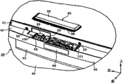
In the inside of housing 1, as shown in Figure 1, door operating device 110 is installed in the refrigerating chamber 20.This door operating device 110 is shown in figure 10; With the o 200 that constitutes by solenoid coil 129 and plunger 134 as drive source; Through work under the state that is still in locked position of coupler at lower slider door 36, lower slider door 36 is carried out from the forwards mobile move operation of locked position of coupler.The detailed structure of this door operating device 110 is described below.
Shown in figure 10, solenoid box 111 is devices of upper surface open, is set at the elongated shape that points to fore-and-aft direction.Be formed with the installed surface 112 of level in the rearward end of this solenoid box 111, as shown in Figure 4, installed surface 112 carries the contact-making surface 64 of the level that places refrigerated container outlet 63 with surface contact state.This solenoid box 111 is a material with synthetic resin, and shown in figure 10 on solenoid box 111, inclined plane 113 is positioned at and is formed at the rear of installed surface 112.Rise in this inclined plane 113 in the past backward, as shown in Figure 4, carries the surface that places refrigerated container outlet 63 with surface contact state.
On the left plate of solenoid box 111; Shown in figure 10; The left side of incision-like is avoided portion 114 and is positioned at and is formed at leading section; On the right plate of solenoid box 111, the right side of incision-like is avoided portion 115 and is positioned at and is formed at leading section, and the left side of solenoid box 111 is avoided portion 114 and the right side and avoided on portion 115 that kind as shown in Figure 4 respectively reclines former frame 27 from the below.On the base plate of this solenoid box 111, shown in figure 10, lug boss 116 is positioned at and is formed on each of left front end and right front end.Each of these two lug bosses 16 forms the tubular of upper and lower surfaces opening, and be shown in figure 11, and the leading section of solenoid box 111 is fixed in preceding frame 27 as follows, that is, from the below through two lug bosses 116 each and with screw threaded in preceding frame 27.This solenoid box 111 is disposed at the central portion of the left and right directions of lower slider door 36; On solenoid box 111; Shown in figure 10, circular arc facial 117 is positioned at and is formed at the whole zone of the mutual cross section of the base plate of header board and solenoid box 111 of solenoid box 111.The cross section along vertical plane of this circular arc facial 117 is set at circular-arc; When the user wants lower slider door 36 push operation each other the time, can be prevented finger injuries at the leading section of lower slider door 36 and solenoid box 111 with banjo splint to locked position of coupler.
In solenoid box 111, shown in figure 12, be formed with solenoid chamber 118.This solenoid chamber 118 forms the concavity of upper surface open, on the antetheca of solenoid chamber 118, is formed with the recess 119 of upper surface open.The inner peripheral surface of this recess 119 is set at circle, and is shown in figure 10 on the inner peripheral surface of recess 119, is inserted with bellows setting tool 120.This bellows setting tool 120 forms and points to the cylindric of fore-and-aft direction, and is shown in figure 12 at the leading section of bellows setting tool 120, be formed with diameter dimension from after the rake 121 that diminishes forward.In the rearward end of this bellows setting tool 120, be fixed with the rectangular back plate 122 bigger than bellows setting tool 120, at the leading section of bellows setting tool 120, be fixed with the rectangular header board 123 bigger than bellows setting tool 120.
On solenoid box 111, shown in figure 12, left plate 124 is positioned at right dull and stereotyped 125 and is formed at solenoid chamber 118.This left plate 124 and right dull and stereotyped 125 each be from the rear across with gap with the opposed vertical parts of the antetheca of solenoid chamber 118; In the antetheca and the gap between the left plate 124 of solenoid chamber 118, be inserted with the back plate 122 of bellows setting tool 120 from the top.This back plate 122 also inserts antetheca and right dull and stereotyped 125 gap each other of solenoid chamber 118 from the top; Because back plate 122 contacts with left plate 124 each with right flat board 125; Thereby prevent bellows setting tool 120 deviation post rearward; And,, thereby prevent bellows setting tool 120 deviation post forwards owing to back plate 122 contacts with the antetheca of solenoid chamber 118; Because header board 123 contacts with the diapire of solenoid chamber 118 with each of back plate 122, thereby prevents that bellows setting tool 120 is to the circumferencial direction deviation post.
On the base plate of solenoid box 111, shown in figure 12, be a plurality of lug boss 126 cylindraceous and be positioned at and be formed at solenoid chamber 118.In this solenoid chamber 118, shown in figure 10, taken in coil box 127.This coil box 127 form upper surface and lower surface each be the quadrangular barrel shape of opening, have header board, back plate, left plate and right plate.On this coil box 127, shown in figure 12, be formed with a plurality of installation portions 128.Each of these a plurality of installation portions 128 forms cylindric, and be shown in figure 10, is embedded in the outer peripheral face of lug boss 126.Bolt is screwed on from the top on the inner peripheral surface separately of these a plurality of lug bosses 126, and coil box 127 is fixed in the solenoid chamber 118 through the fastening force of a plurality of bolts.
In coil box 127 inside, shown in figure 10, be fixed with solenoid coil 129.This solenoid coil 129 forms and points to the cylindric of fore-and-aft direction, the coiling of solenoid coil 129 begin the end and the end end of reeling each be connected with power line 130.On solenoid box 111, be formed with peristome 131.This peristome 131 is configured in the left back bight of solenoid box 111, and each of two power lines 130 pulled into the outside of solenoid box 111 through peristome 131.
On each of two power lines 130, shown in figure 12, common connector 132 is positioned at and is connected in the outside of solenoid box 111, and connector 132 is connected in power circuit via paired connector.This power circuit is accommodated in the Machine Room 17 of housing 1, on solenoid coil 129, applies driving power from power circuit through two power lines 130.On these power circuits and solenoid coil 129 supply path each other, there is the contact of relay.The contact of this relay is the open type contact that under the electric cut-off state of relay coil, stays open the open mode of supply path, through making the relay coil electrically conducting, switch to the closed condition of closing supply path.That is, on solenoid coil 129, under the electrically conducting state of relay coil, apply driving power, under the electric cut-off state of relay coil, block driving power from power circuit.
On the back plate of coil box 127, shown in figure 13, form circular through hole 133, in the inside of solenoid coil 129, from the rear through through hole 133 and forwards, backwards the direction straight line be inserted with columned plunger 134 movably.This plunger 134 is made up of magnetic materials such as iron, is configured in the central portion of the left and right directions of lower slider door 36.In the rearward end of this plunger 134, be fixed with the diameter dimension circular convex edge 135 bigger than plunger 134, in solenoid box 111, limiter 136 is positioned at and is fixed in the rear of convex edge 135.
On the outer peripheral face of plunger 134, shown in figure 13, backspring 137 be positioned at and the back plate and the convex edge 135 that are inserted in coil box 127 each other.This backspring 137 is made up of compression disc spring, and when blocking the driving power of solenoid coil 129, plunger 134 is operation rearward through the spring force of backspring 137, and thus, convex edge 135 remains on the going-back position that contacts with limiter 136.When from power circuit when this solenoid coil 129 applies driving power, magnetic attraction acts in the plunger 134 from solenoid coil 129, thus, plunger 134 overcomes the spring force of backspring 137 and forwards moves from going-back position.Advancing of this plunger 134 is shown in figure 14; Because the wire rod of backspring 137 contacts each other; Thereby stop at progressive position; When the driving power of solenoid coil 129 was blocked, plunger 134 reset to going-back position through the spring force of backspring 137 from the progressive position that wire rod contacts each other.
On solenoid box 111, shown in figure 13, be fixed with plastic solenoid lid 138.It is 138 shown in figure 10 that this solenoid covers; Have the lower surface opening concavity lid main body 139 with surround the flange 140 that covers main body 139; On lid main body 139; Be formed with the semicircular recess 141 that contacts with the outer peripheral face face of bellows setting tool 120, on flange 140, be formed with a plurality of through holes 142.This flange 140 carries from the top on the locular wall that places solenoid chamber 118, and solenoid lid 138 passes each of a plurality of through holes 142 and engages with the locular wall of solenoid chamber 118 through screwing togather bolt from the top.At the locular wall of the flange of this helical shroud 138 140 and solenoid chamber 118 each other, shown in figure 13, be separated with seal 143 by formation such as EPDM (ethylene propylene diene rubber) rubber of etc.ing.Sealing part 143 is flexibly flattened at the locular wall of flange of helical shroud 138 140 and solenoid chamber 118 each other; The flange 140 of helical shroud 138 contacts through elastic restoring force with each of the locular wall of solenoid chamber 118; Thus, the flange 140 of helical shroud 138 and the locular wall of solenoid chamber 118 are sealed into airtight conditions each other.
At the leading section of plunger 134, shown in figure 13, be fixed with the rearward end of the connector rod 144 that points to fore-and-aft direction.This connector rod 144 forms and concentric cylindric of plunger 134, and the diameter dimension of connector rod 144 is set forr a short time than the diameter dimension of plunger 134.The leading section of this connector rod 144 connects the header board of coil box 127 and gives prominence to the place ahead of coil box 127, and the inside that connects bellows setting tool 120 is also outstanding to the place ahead of bellows setting tool 120.On the outer peripheral face of this connector rod 144, be inserted with the bellows 145 of rubber system.This bellows 145 forms diameter dimension and becomes big cylindric from an end to the other end, and the diameter dimension in the bellows 145 is formed with clamping part 146 on big the other end.This clamping part 146 form diameter dimension from after diminish forward cylindric, and be pressed into the outer peripheral face of the rake 121 of bellows setting tool 120.On the rake 121 of this bellows setting tool 120, chimeric from the top of the clamping part 146 of bellows 145 have a bellows pusher 147.This bellows pusher 147 form diameter dimension from after diminish forward cylindric; The clamping part 146 of bellows 145 is fixed with bellows pusher 147 through the rake 121 that is clamped in bellows setting tool 120 each other, and bellows 145 prevents to reverse in a circumferential direction via bellows setting tool 120.
The end that diameter dimension in bellows 145 is little, shown in figure 13, be formed with bowl cover 148.This bowl cover 148 forms the bag shape of an end of locking bellows 145; The inner space of bellows setting tool 120 is sealed as airtight conditions through bellows 145; Thereby moisture can't be invaded from the outside; The inner space of solenoid chamber 118 is airtight conditions through helical shroud 138, seal 143 and bellows 145 threes by locking, thereby moisture can't be invaded from the outside.The inside of the bowl cover 148 of this bellows 145 has been pressed into head 149.This head 149 is formed at the leading section of connector rod 144; The leading section of connector rod 144 through bowl cover 148 and head 149 each other the tight power of connection and be linked to an end of bellows 145 with the spline state, connector rod 144 via bellows 145 and bellows setting tool 120 separately and stop.
Shown in figure 13, bellows 145 is to be maintained under the state of going-back position the mode of giving prominence to the place ahead of bellows setting tool 120 separately an of end and the other end in plunger 134; Part midway at fore-and-aft direction is turned back, and is shown in figure 14, corresponding with advancing of plunger 134; The mode elastic deformation that bellows 145 forwards moves with fold back portion thus, allows plunger 134 to move from the going-back position advanced position; Corresponding with retreating of plunger 134; The mode elastic deformation that bellows 145 rearward moves with fold back portion thus, allows plunger 134 to move from the progressive position position of drawing back.
On the base plate of solenoid box 111, shown in figure 12, be formed with left space bar 150 and right septum plate 151 respectively.Each of this left side space bar 150 and right septum plate 151 is meant the vertical parts of direction forwards, backwards; Each of the rearward end of left side space bar 150 and the rearward end of right septum plate 151 is connected in the antetheca of solenoid chamber 118, and each of the leading section of the leading section of left space bar 150 and right septum plate 151 is connected in the header board of solenoid box 111.And opposed each other on left and right directions, left space bar 150 and right septum plate 151 are formed with the bar receiving room 152 of space shape to each of this left side space bar 150 and right septum plate 151 each other across the gap.
In the bar receiving room 152 of solenoid box 111, shown in figure 12, taken in push rod 153.This push rod 153 is that material forms with synthetic resin, has propeller 154, arm 155 and connector 156.This connector 156 forms the quadrangular barrel shape of the lengthwise of lower surface locking, on the rear wall of connector 156, is formed with the slot part 157 of upper surface open.In this slot part 157, shown in figure 13, be inserted with the leading section of connector rod 144 from the top, connector rod 144 is sticked in the rear wall of connector 156 jointly through the bowl cover 148 of head 149 and bellows 145, and is connected in connector 156.Propeller 154 is shown in figure 12, forms the solid quadrangular prism shape in centre that points to fore-and-aft direction, and is shown in figure 15, is disposed at the central portion of the left and right directions of lower slider door 36.This propeller 154 is shown in figure 13, is configured in the position lower than connector rod 144, and the lower surface of folder former frame 27 and the bottom surface of solenoid box 111 are each other.Arm 55 jointing connector 156 are mutual with propeller 154, form the tabular of the level of pointing to fore-and-aft direction.
At the leading section of propeller 154, shown in figure 10, be fixed with buffer 158, on solenoid box 111, peristome 159 is positioned at and is formed at the place ahead of buffer 158.This buffer 158 is made up of each all soft padded coaming such as rubber than the plate behind the door 41 of propeller 154 and lower slider door 36; Under the solenoid coil 129 electric states that end; Push rod 134 remains on going-back position, so that the front surface of buffer 158 is rearward kept out of the way from the front surface of the header board of solenoid box 111.This propeller 154 is shown in figure 14; Under the state of solenoid coil 129 electrically conductings, outstanding through the peristome 159 of solenoid box 111 to the place ahead of solenoid box 111, be still at lower slider door 36 under the state of locked position of coupler; When solenoid coil 129 electrically conductings; Propeller 154 is outstanding to the place ahead of solenoid box 111, thus, with the central portion of the left and right directions of lower slider door 36 from after pushing forward.Buffer 158 is the devices that when propeller 154 conflicts with the plate behind the door 41 of lower slider door 36, relax impulsive force; Each of locking magnet 51 and electromagnet 37 is disengaged the absorption of lower slider door 36 pushing force through propeller 154, and lower slider door 36 forwards moves from locked position of coupler through the pushing force of propeller 154.
Propeller 154 is as shown in Figure 5, and the first half is relative from the interior sealing 50 of rear and liner 45, and the going-back position of propeller 154 is set as follows,, at the locked position of coupler of lower slider door 36, forms the gap at interior sealing 50 each other with buffer 158 that is.On the front surface of this propeller 154, be set with seal pushing portion 160 and door pushing portion 161.Seal pushing portion 160 is meant; At the locked position of coupler of lower slider door 36 via buffer 158 from the relative part of the interior sealing of rear and liner 45 50; Door pushing portion 161 is meant, at the locked position of coupler of lower slider door 36 via buffer 158 from the relative part of the rope form reinforcing steel of rear and lower slider door 36 52, be still at lower slider door 36 under the state of locked position of coupler; When solenoid coil 129 during by electrically conducting; Plunger 134 is moved from the going-back position advanced position, through the locomotivity that plunger 134 is moved from the going-back position advanced position, and propeller 154 pushing lower slider doors 36; Thus, carry out from the forwards mobile move operation of locked position of coupler.The action of this propeller 154 is described below.
When solenoid coil 129 at the locked position of coupler of lower slider door 36 during by electrically conducting; As shown in Figure 5; Before the door pushing portion 161 of propeller 154 contacts the rope form reinforcing steel 52 of lower slider doors 36; The seal pushing portion 160 of propeller 154 forwards pushes via the interior sealing 50 of buffer 158 with liner 45, makes its elastic deformation thus.In this under elastic deformation state of sealing 50; The door pushing portion 161 of propeller 154 forwards pushes via the rope form reinforcing steel 52 of buffer 158 with lower slider door 36; Thus, the locking magnet 51 of lower slider door 36 is peeled off from header board 21, each of two magnetic sheets of lower slider door 36 peeled off from electromagnet 37; Move operation shown in figure 16, that lower slider door 36 is forwards moved from locked position of coupler.Under rope form reinforcing steel 52 state of contact of door pushing portion 161 via buffer 158 and lower slider door 36 of this propeller 154; The first half of buffer 158 is relative with the installed surface 44 of plate 41 behind the door across the gap; The interior sealing 50 of the seal pushing portion 160 pushing liners 45 of propeller 154, thus interior sealing 50 is flattened fully.
On the left space bar 150 of solenoid box 111, shown in figure 12, be formed with left front guide 162 and left back guide 163, on the right septum plate 151 of solenoid box 111, be formed with right front guide 164 and right back guide 165.Each of this left front guide 162~right back guide 165 is outstanding in bar receiving room 152, is formed with the gap each other at the lower surface separately of left front guide 162~right back guide 165 and the bottom surface of bar receiving room 152.This left front guide 162 is clamped arm 155 with right front guide 164 and is opposed each other on left and right directions; This left back guide 163 is clamped arm 155 with right back guide 165 and is opposed each other on left and right directions; Each when plunger 134 is advanced when retreating; Arm 155 is by left front guide 162~right back guide 165 these 4 parts guiding, thereby the direction straight line moves forwards, backwards.Figure 13 representes the going-back position of plunger 134; Figure 14 representes the progressive position of plunger 134; Arm 155 do not receive plunger 134 forward-reverse influence and be accommodated in the solenoid box 111; Each of left front guide 162~right back guide 165 do not contact with propeller 154, and only to arm 155 channeling conducts.
On solenoid box 111, as shown in Figure 3, be coated with lid 166.This lid 166 is as shown in Figure 4, has top board, left plate, right plate and header board, and the upper surface of solenoid box 111 is through lid 166 lockings.On each of the left plate of this lid 166 and right plate, shown in figure 10, claw 167 is positioned at and is formed at the central portion of fore-and-aft direction.Each of these two claws 167 is outstanding towards the central portion of the left and right directions of solenoid box 111, and inserts in the holding section 168.Each of these two holding sections 168 is formed on the solenoid box 111, forms the concavity of lower surface opening.Each of these two holding sections 168 has the ceiling face, and each of two claws 167 is sticked in the ceiling face of holding section 168 from the below, thus, prevents that solenoid lid 166 from coming off from solenoid box 111.That is, the leading section in the upper surface of solenoid box 111 is through preceding frame 27 lockings of housing 1, and the remainder of removing leading section in the upper surface of solenoid box 111 is through lid 166 lockings.
At the leading section of lid 166, as shown in Figure 3, be formed with location teat 169.This location teat 169 is outstanding downwards from the top board of lid 166, forms to point to the vertical tabular of left and right directions.This location teat 169 is sticked in the slot part 170 of location.This location slot part 170 is formed at the preceding frame 27 of housing 1, and lid 166 remains on target location with location slot part 170 mutual engaging power with respect to preceding frame 27 through location teat 169.
On solenoid box 111, shown in figure 11, a plurality of left banks water hole 171 and a plurality of right osculums 172 are positioned at and are formed at the base plate of bar receiving room 152.When each of this a plurality of left banks water hole 171 and a plurality of right osculums 172 produces dewfall in bar receiving room 152 dew in the bar receiving room 152 is discharged to the outside of solenoid box 111; Each of a plurality of left banks water hole 171 is shown in figure 12; Be set at left space bar 150 be basic point to right-hand linearly extended slit-shaped, it is that basic point is to the linearly extended slit-shaped of left that each of a plurality of right osculums 172 is set at right septum plate 151.Door operating device 110 constitutes as above-mentioned, is installed in the inside of housing 1 with following order.
In order door operating device 110 to be installed on the inside of housing 1; As shown in Figure 4; The installed surface of the level of solenoid box 111 was placed in 112 years on the contact-making surface 64 of level of refrigerated container outlet 63, the inclined plane 113 of solenoid box 111 is pressed against refrigerated container export on 63 the surface.Export under 63 state of contact with last refrigerated container in each that makes this installed surface 112 and inclined plane 113, pass each of two lug bosses 116 of solenoid box 111 from the below, and with screw threaded in preceding frame 27, frame 27 before solenoid box 111 is fixed in.Export under 63 state of contact with last refrigerating chamber in each of this installed surface 112 and inclined plane 113; Solenoid box 111 is located on fore-and-aft direction with respect to preceding frame 27, and the bolt in each of two lug bosses 116 of insertion solenoid box 111 and the target location of preceding frame 27 coincide.
When solenoid box 111 is fixed in the inside of housing 1; Location teat 169 from the top with lid 166 inserts in the location slot part 170 of solenoid box 111; Under the mutual fastening state of location teat 169 and location slot part 170, the rearward end of lid 166 is pressed into downwards.Like this; The left plate of solenoid box 111 is by claw 167 pushings of the left side of lid 166; And carry out elastic deformation thus; The right plate of solenoid box 111 is pushed by the claw 167 of the right side of lid 166, and carries out elastic deformation thus, and each of two claws 167 of lid 166 is sticked in the holding section 168 of solenoid box 111.Under the mutual fastening state of this location teat 169 and location slot part 170, in the fore-and-aft direction location, each of two claws 167 of lid 166 is identical with the holding section of solenoid box 111 168 with respect to solenoid box 111 for lid 166.
In the inside of housing 1, as shown in Figure 1, substrate box 171 is fixed in the top of Machine Room 17.This substrate box 171 has been taken in the control substrate, is equipped with control circuit on the control substrate.This control circuit is that main body constitutes with the micro computer, has CPU, ROM and RAM.On this control circuit; Electrically each of door switch 70 and press button 94 carried out distribution via the distribution flexible cord; Control circuit is based on judging that from the output signal of door switch 70 whether lower slider door 36 is positioned at locked position of coupler, has judged whether to carry out the push operation of push operation button 86 based on the output signal from press button 94.Relay coil is connected in this control circuit; Control circuit carries out break-make corresponding to the electric state separately of door switch 70 and press button 94 to relay coil; Thus, carry out the opening and closing operations of the contact of relay, thereby solenoid coil 129 is carried out electrically conducting by control.
Figure 17 is the flow chart that is used for explaining the control program of the ROM that is recorded in control circuit in advance, and the contents processing of control circuit is described based on the control program of Figure 17.When the CPU of control circuit turn-on power, in step S1, whether conducting of decision gate switch 70.For example, be still at lower slider door 36 under the state of locked position of coupler, in step S1, be judged as door switch 70 conductings, in step S2, timer T1 is reset to " 0 ".This timer T1 is that to return locked position of coupler be the device that benchmark is measured the elapsed time to following sliding door 36; CPU starts the timer relay process with predetermined certain time interval; When starting the timer relay process, measure the elapsed time through in timer T1, predetermined unit value being carried out add operation.
When CPU in step S2 during replacement timer T1, whether decision gate switch 70 ends in step S3.For example, manually lower slider door 36 is operated from locked position of coupler under the situation of front side, door switch 70 is switched to cut-off state from conducting state in user's inoperation action button 86.In this case, CPU is judged to be door switch 70 in step S3 ends, and turns back to step S1.Turn back under the situation of locked position of coupler at this lower slider door 36, CPU is judged to be door switch 70 conductings in step S1, in step S2, timer T1 is reset to " 0 ".
Be still at lower slider door 36 under the state of locked position of coupler, CPU is judged as door switch 70 in step S3 does not end, and in step S4, judges whether conducting of press button 94.For example; Be still at lower slider door 36 under the state of locked position of coupler; When the user carried out push operation to action button 86, CPU was judged as press button 94 conductings in step S4, in step S5, the result and the action of the add operation of timer T1 was forbidden that time T w (for example 1.5 seconds) relatively.This action forbids that time T w is recorded among the ROM of control circuit in advance, and the result who in step S5, is judged as the add operation of timer T1 at CPU does not reach action and forbids turning back to step S3 under the situation of time T w.That is, in user's push operation action button 86, lower slider door 36 is returned under the situation of locked position of coupler, the add operation result who is judged as at timer T1 does not reach action and forbids conducting press button under the state of time T w.In this case, being disabled of conducting of press button 94, door operating device 110 is not worked.
When the add operation result who in step S5, is judged as timer T1 as CPU reaches action and forbids time T w; In step S6 with the relay coil conducting; Thus, apply driving power to solenoid coil 129, in step S7, timer T3 is reset to " 0 " from power circuit.This timer T3 measures the application time that solenoid coil 129 is applied driving power; CPU starts the timer relay process with predetermined certain time interval; When starting the timer relay process, measure application time through in timer T3, predetermined unit value being carried out add operation.
When CPU in step S7 during replacement timer T3, whether decision gate switch 70 ends in step S8.For example, under the situation that does not have effect above the excessive load of the pushing force of propeller 154 on the lower slider door 36, begin solenoid coil 129 is applied driving power, thus, lower slider door 36 forwards moves from locked position of coupler, and door switch 70 ends.In this case, CPU is judged to be door switch 70 in step S8 ends, and advances to step S9.
When CPU in step S8, be judged as door switch 70 by the time, in step S12 with the add operation result of timer T3 be stored among the ROM standby limit time T f in advance relatively.This standby limit time T f is in order to prevent owing on solenoid coil 129, applying the boundary value that driving power causes solenoid coil 129 unusual situation about heating up continuously; The add operation result who in step S12, is judged as timer T3 at CPU does not reach under the situation of standby limit time T f, turns back to step S8.That is, begin driving with solenoid coil 129 and have nothing to do, under the forwards mobile situation of locked position of coupler, solenoid coil 129 is not that limit is switched on continuously with standby limit time T f to lower slider door 36.
Before through standby limit time T f, to remove from lower slider door 36 under the situation of excessive load, lower slider door 36 forwards moves from locked position of coupler through the pushing force of propeller 154, and door switch 70 ends.In this case, CPU is judged as door switch 70 in step S8 ends, and advances to step S9.Even do not removing under the situation of excessive load from lower slider door 36 through standby limit time T f; CPU is judged as " T3 >=Tf " in step S12; In step S11, through relay coil is ended, thereby cut off the driving power of solenoid coil 129.
When CPU advances to step S9, timer T2 is reset to " 0 ".This timer T2 measures the elapsed time; This elapsed time is that benchmark is measured the elapsed time through on solenoid coil 129, applying driving power with the situation that door switch 70 ends; CPU starts the timer relay process with predetermined certain time interval; When starting the timer relay process, measure the elapsed time through in timer T2, predetermined unit value being carried out add operation.
When CPU in step S9 during replacement timer T2, in step S10 with the add operation result of timer T2 be recorded in advance Te conduction time among the ROM (<Tf) relatively.This conduction time, Te was equivalent to make the application time that plunger 134 is needed from the move operation that the going-back position advanced position moves, solenoid coil 129 applied driving power; The add operation result who in step S10, is judged as timer T2 at CPU reaches under the situation of Te conduction time; Advance to step S11, cut off the driving power of solenoid coil 129 through the cutoff relay coil.When cutting off this driving power; Lower slider door 36 is urged into device 154 pushings, thus, forwards moves from locked position of coupler; The user through on the handle portion 66 that finger is hung over lower slider door 36 and with lower slider door 36 to the operation of side nearby, can pull it open position.
Figure 18 is that the conducting of expression press button 94 ends, the conducting of solenoid coil 129 ends, the conducting of door switch 70 ends, the accompanying drawing of the dependency relation of the time of the switching of lower slider door 36; Be still at lower slider door 36 under the state of locked position of coupler; Through the push operation of carrying out action button 86 is pressed into; Under the situation of press button 94 conductings; With the conducting of press button 94 in time synchronously with solenoid coil 129 conductings, door switch 70 ends than the conducting of toroidal winding 129 in time lately.Under the state that this lower slider door 36 forwards moves from locked position of coupler; When operating operation button 86; In the surveyed area of press button 94, do not act on effective magnetic force from button magnet 90, press button 94 can conducting, so; Solenoid coil 129 not conductings, door operating device 110 is not worked.
Under the state that locked position of coupler forwards moves, be pushed into when being operated to locked position of coupler at lower slider door 36, door switch 70 conductings, thus, timer T1 resets to " 0 ", and carrying out with timer T1 " 0 " be the add operation processing of benchmark.When the mode of operation in action button 86 carries out the push operation of this lower slider door 36; Door switch 70 conductings; Therewith in time synchronously; Detect the conducting of press button 94,, add operation result and the action of timer T1 are forbidden that time T w compares through detecting the conducting of press button 94.In this case,, the add operation result of timer T1 do not forbid time T w because reaching action, so, solenoid coil 129 not conductings, door operating device 110 is not worked.Even under the situation of the push operation of carrying out this lower slider door 36 under the non-operating state of action button 86, when the add operation result at timer T1 reaches action and forbids before the time T w operating operation button 86, solenoid coil 129 not conductings; Door operating device 110 is not worked; Reach action in the add operation result of timer T1 and forbid under the state of time T w, when operating operation button 86, solenoid coil 129 conductings; Thus, door operating device 110 work.
Effect below the foregoing description produces.
Operation corresponding to action button 86; Button magnet 90 moves to active position from inoperative position; Button magnet 90 moves to active position from inoperative position situation is detected with non-contacting mode by press button 94, thus, and driving gate operating means 110; So, there is no need to dispose the distribution flexible cord each other at lower slider door 36 and housing 1.Therefore, the structure of covering distribution flexible cord need be set for finger is not contacted with the distribution flexible cord with water, and, do not need to make in advance the distribution flexible cord can be corresponding to the change of wiring distance, so total structure becomes simple.
Owing on the base plate of mechanism chamber 68, form bolster 87; Through bolster 87 from the below supporting device chamber cap 95; So, the stuffing pressure during through filling-foam polyurethane 39 in door box 38, the base plate of mechanism chamber 68 is to the top bulging; In this case, mechanism's chamber cap 95 is supported axle 87 and lifts to equidirectional.Therefore, the influence of the pressure the when height dimension of mechanism chamber 68 does not receive filling-foam polyurethane 39 is maintained desired value, so, prevent to cause that owing to the upper surface interference mechanism chamber cap 95 of magnet platform 88 action is bad.
Each of left arm 71, right arm 73, backspring 77, magnet platform 88, button magnet 90 is accommodated in the common mechanism chamber 68, and mechanism's chamber cap 95 that the upper surface of mechanism chamber 68 can be loaded and unloaded blocks.Therefore, through mechanism's chamber cap 95 is unloaded from mechanism chamber 68, can be once each of left arm 71~button magnet 90 be carried out maintenance, so, to compare with each the situation that disposes left arm 71~button magnet 90 each other dispersedly, the maintenance transfiguration is prone to.
The installed surface 44 that button magnet 90 is compared the back surface of lower slider door 36 from the part of the motion track ML of inoperative position when active position moves is rearward outstanding.Therefore because button magnet 90 is near press button 94, therefore can through button magnet 90 reliably conducting by press button 94.At chamfered section 93 and press button 94 opposed inoperative positions and long leg 91 and press button 94 opposed active positions each other, button magnet 90 is carried out move operation in a circumferential direction.Therefore; When button magnet 90 was positioned at inoperative position, the magnetic force that acts on press button 94 from button magnet 90 died down, when button magnet 90 is positioned at active position; Act on the magnetic force grow of press button 94 from button magnet 90; So, because this point, through button magnet 90 reliably conducting by press button 94.And; According to chamfered section 93 towards with rectangular contour shape towards each; Can discern the posture of the button magnet 90 when button magnet 90 is assembled in magnet platform 88, so, can prevent button magnet 90 to be assembled in magnet platform 88 with the posture of mistake.
With from cam path 89 and the modes that button magnet 90 does not overlap each other when the above-below direction of the bolster 87 of magnet platform 88 is observed, both are configured on the magnet platform 88 with being separated from each other in the horizontal direction.Therefore, owing to avoided the pin 81 in the cam path 89 to interfere with button magnet 90, so, need not make the upper surface come-up of the lower surface of button magnet 90 from magnet platform 88, therefore, can prevent that the width dimensions of the above-below direction of lower slider door 36 from becoming big.
The left side axle 72 of left arm 71 and right 74 of right arm 72 are configured on the common straight line that direction is extended to the left and right, set left side axle 72 and axis 75 distance each other identical with axis 75 distance each other with right 74.Therefore, through action button 86 is carried out push operation, axis 75 moves in the past backward as the crow flies, so action button 86 does not tilt when push operation.79 pairs of action buttons of limiter 86 are carried out position limit; So that when action button 86 is carried out push operation, make button magnet 90 stop at the mode of active position; This limiter 79 is made up of padded coamings such as rubber; Therefore, can prevent when carrying out the push operation of action button 86, to produce impact sound.
Removing from action button 86 under the situation of operating physical force, limiting left arm 71 and right arm 73 position separately respectively through limiter 79, thereby, make button magnet 90 stop at inoperative position.Therefore, when action button 86 is removed operating physical force, can prevent the generation of impact sound.Make action button 86 from frontal collisions limiter 79, each that makes left arm 71 and right arm 73 is from rearward collision limiter 79.Therefore, can carry out position limit through each of 79 pairs of action buttons 86 of common limiter, left arm 71 and right arm 73, so, the cheap and property made raising.
Carry out the operation of push operation button 86 by error and lower slider door 36 is returned under the situation of locked position of coupler the user, when lower slider door 36 arrived locked position of coupler, action button 86 was detected in the operated situation of operating position.In this case,, the mensuration result of timer T1 do not forbid time T w because reaching action, so, on solenoid coil 129, do not apply driving power.Therefore, owing to door operating device 110 is not worked, so, can prevent inadvertently to apply impact force to the user from the propeller 154 of door operating device 110.
Under situation about driving power being applied on the solenoid coil 129; Judge whether lower slider door 36 is still in locked position of coupler; Be still under the situation of locked position of coupler being judged as lower slider door 36; Begin to measure application time T3, reach standby limit time T f to the mensuration result of application time T3 till, constantly to solenoid coil 129 energisings.Therefore, before the mensuration result of application time T3 reaches standby limit time T f, remove the user under the situation of excessive load, lower slider door 36 forwards moves from locked position of coupler.Therefore, after the user removed excessive load, time and the work that need not operate action button 86 were so ease of use improves again.And, reach in the mensuration result who is judged to be application time T3 under the situation of standby limit time T f, owing to cut off the driving power of toroidal winding 129, so, can prevent the unusual intensification of solenoid coil 129.
In the above-described embodiments, in the past during backward operation lower slider door 36, also can use the feed mechanism of lower slider door 36 being drawn in locked position of coupler with the power of machinery.In this case; Can on each of two second movable tracks 35 of lower slider door 36, pin be set, in the past during backward operation lower slider door 36, each that makes two pins is sticked in draws in parts; Parts are drawn in spring force operation through spring, thereby lower slider door 36 is drawn in locked position of coupler.
In the above-described embodiments, also can replace rectangular button magnet 90 and use foursquare button magnet.Under the situation of using this structure; Owing to there is mistaken polarity button magnet 90 is installed on the possible of magnet platform 88; So, preferably adopt following structure, promptly; Bight through at button magnet 90 forms inclined plane or painted on button magnet 90, prevents the structure of the mistake installation of button magnet 90.Under the situation that adopts this structure; Can on foursquare button magnet, form chamfered section; At chamfered section and press button 94 opposed inoperative positions and foursquare one side portion and press button 94 opposed active positions each other, foursquare button magnet is carried out move operation in a circumferential direction.
In the above-described embodiments, can use the drive source of motor as door operating device 110.
In the above-described embodiments, whole installed surfaces 44 of comparing lower slider door 36 of the motion track ML of button magnet 90 are rearward given prominence to.
Industrial applicibility
Refrigerator of the present invention can as not door and housing exist each other the distribution flexible cord, the user can make the refrigerator of door operating device work use from the place ahead.