CN1017507B - Apparatus for cutting, drilling or similar machining stone. ores or similars - Google Patents
Apparatus for cutting, drilling or similar machining stone. ores or similarsInfo
- Publication number
- CN1017507B CN1017507B CN88106530A CN88106530A CN1017507B CN 1017507 B CN1017507 B CN 1017507B CN 88106530 A CN88106530 A CN 88106530A CN 88106530 A CN88106530 A CN 88106530A CN 1017507 B CN1017507 B CN 1017507B
- Authority
- CN
- China
- Prior art keywords
- shower nozzle
- nozzle
- pipe
- control valve
- swing pipe
- Prior art date
- Legal status (The legal status is an assumption and is not a legal conclusion. Google has not performed a legal analysis and makes no representation as to the accuracy of the status listed.)
- Expired
Links
Images


Classifications
-
- E—FIXED CONSTRUCTIONS
- E21—EARTH DRILLING; MINING
- E21C—MINING OR QUARRYING
- E21C25/00—Cutting machines, i.e. for making slits approximately parallel or perpendicular to the seam
- E21C25/60—Slitting by jets of water or other liquid
-
- B—PERFORMING OPERATIONS; TRANSPORTING
- B05—SPRAYING OR ATOMISING IN GENERAL; APPLYING FLUENT MATERIALS TO SURFACES, IN GENERAL
- B05B—SPRAYING APPARATUS; ATOMISING APPARATUS; NOZZLES
- B05B3/00—Spraying or sprinkling apparatus with moving outlet elements or moving deflecting elements
-
- B—PERFORMING OPERATIONS; TRANSPORTING
- B26—HAND CUTTING TOOLS; CUTTING; SEVERING
- B26F—PERFORATING; PUNCHING; CUTTING-OUT; STAMPING-OUT; SEVERING BY MEANS OTHER THAN CUTTING
- B26F3/00—Severing by means other than cutting; Apparatus therefor
- B26F3/004—Severing by means other than cutting; Apparatus therefor by means of a fluid jet
-
- B—PERFORMING OPERATIONS; TRANSPORTING
- B28—WORKING CEMENT, CLAY, OR STONE
- B28D—WORKING STONE OR STONE-LIKE MATERIALS
- B28D1/00—Working stone or stone-like materials, e.g. brick, concrete or glass, not provided for elsewhere; Machines, devices, tools therefor
-
- E—FIXED CONSTRUCTIONS
- E21—EARTH DRILLING; MINING
- E21B—EARTH DRILLING, e.g. DEEP DRILLING; OBTAINING OIL, GAS, WATER, SOLUBLE OR MELTABLE MATERIALS OR A SLURRY OF MINERALS FROM WELLS
- E21B7/00—Special methods or apparatus for drilling
- E21B7/18—Drilling by liquid or gas jets, with or without entrained pellets
Abstract
To cut, bore or similarly machine rock, ore, stratified coal or other objects, a medium is delivered under high pressure through a supply pipe to a nozzle. The supply pipe is designed as a pendulum-type pipe, in particular in the form of a flexible high-pressure hose, and executes, together with the nozzle, rapid, for example oscillating and/or circular, movements along a guide. In this way, straight cuts and/or holes can be made very rapidly and simple in rock. The cut width can be controlled by the arrangement and fitting in particular of a plurality of nozzles, depending on the rock and pressure medium. In particular, an eccentric element which functions as a drive mechanism permits a circular movement of the nozzle.
Description
The present invention relates to a kind of special device in order to cutting and drilling rock, ore, natural rock, concrete or similar substance, perhaps a kind of utilize pressure medium to the processing material cut, the device of boring or similar processing, wherein pressure medium is by delivering to a shower nozzle as the input pipe of swing pipe, and becomes the jet on the directing force worker material in an angle of oscillation by at least one nozzle; A drive unit drives this swing pipe extends substantially transversely to jet direction with generation oscillating motion in this device.
A kind of such device known (GB-PS1460711).One of them shower nozzle is offset by the drive train that is in the oscillating movement state perpendicular to the jet direction of the pressure medium that is flowed out by nozzle bore.Ultrasonic transducer, electromechanical converter and drive unit machinery or hydraulic pressure all can be used as drive train.This shower nozzle is bearing on the bearing, or can linearly move, maybe can be around bolster swing.Yet it is to be noted that when when swinging than higher frequency, this seat wear gets very fast, but this high frequency still is recommendable to effective cutting.
Same problem occurs in (GB-PS 2027776) in the another one known devices, if bearing journal of no use here as bearing, this device equally also has the shower nozzle that has a cam and moves back and forth on a line slideway of bearing.This device utilizes a kind of liquid jet to be used to remove steel concrete or removes the flooring overburden.
In addition, also known is that (DE-OS 3516572) dispose a shower nozzle on a flexible high-pressure hose, and this shower nozzle is being equipped many nozzles, in the distolateral screw-in shower nozzle of these nozzles.Intermediate noxzzle is then disposing two other nozzle in the axial stretching, extension of shower nozzle in the both sides of intermediate noxzzle, and these two nozzles have the axis that relative shower nozzle axis tilts.This shower nozzle has proved good to cutting rock.
Last known (DE-OS 2607097) are, shower nozzle that nozzle is housed is fixed on one can be on the pipe of gantry pillars swing, this pipe away from the end of shower nozzle by an eccentric part, for example a crank gear moves on perpendicular to a circuit orbit in the plane of tubular axis.
The present invention is based on such task, a kind of processing unit (plant) with things such as high-pressure medium cutting or drilling rock, ore, concrete is provided, device of the present invention has been done improvement to the operability of the device of aforementioned type.Like this, hope at first is to make a more elongated device, and makes it and can operate in length and narrow slit, perforation or the similar opening in rock for example.It is excellent more that this device also should seem owing to its long life.In addition, the improvement of device of the present invention also is embodied in manufacture view can not must be changed and takes much more and the shower nozzle of its assembling must not occupy very large space, also improves the operability of this shower nozzle simultaneously.Welcome is the process operation of the high speed of device of the present invention, and the slot-shaped exploitation that for example is used in rock, rock stratum and similar substance is that effectively the material such as the slot-shaped exploitation such as granite and marble that particularly are used in high rigidity are especially effective.
For realizing above-mentioned purpose of the present invention, a device is provided, device of the present invention is except that the technical solution with aforementioned prior art, technical solution of the present invention also comprises and being characterised in that, drive train acts on the flexible or expandable swing pipe, this drive train is bearing on the rigidity control valve, control valve then is parallel to input pipe or jet direction stretches, this control valve is transmitted to drive train with the excitation drive train with energy carrier, also have a guiding device that is used for swing pipe, and this swing pipe is driven on the direction transverse to jet with shower nozzle.At this, in any case the part of input channel will be made swing pipe, in this case, drive train acts on the swing pipe through a clutch group.Under one " swing pipe ", disposing the such input pipe fitting that is used for shower nozzle especially, when work shower nozzle be substantially perpendicular to the axis of nozzle or intermediate noxzzle and realizing a kind of the reciprocating motion or a kind of circle in the plane of extending, even oval-shaped motion, from side, this " swing " motion laterally changes jet direction, by this " swing " or the motion of waving, when jet is wanted on the processed material at bump, (suppose from rum point, and remove another resting position that " swing " input pipe fitting is also supposed this device outward) marks straight line or curve.
This drive train is bearing on the control valve, and this control valve is arranged essentially parallel to input pipe and stretches.
Control valve transmits energy carrier with the excitation drive train, for example arrives the mechanical rotation movement of drive train, and kinetic energy just, and control valve has a guiding device that is used for swing pipe.This guiding device also can be made of drive train itself.
Swing pipe itself can be the comparison rigidity, and its clutch particularly flexible by one and/or swing links to each other with input pipe, and at this, to be in connection status be proper if swing pipe additionally passes through one or more springs and control valve.Like this, the driving energy from drive train transmits stronger oscillating motion through this spring.Yet, can also use one flexible but also have the swing pipe of enough intrinsic rigidities, so that shower nozzle is enough to by swing pipe supporting itself and guiding, this last described replacement scheme even preferential the selection, at this, shower nozzle be fixed on one flexible and on the interior free end of depressing expandable high-pressure hose.
According to a special structure of the present invention, shower nozzle has the nozzle of a plurality of different drift angles like this, promptly the axis of nozzle not in a public straight plane, the axis of this nozzle relatively shower nozzle major axis and be offset.In this structure of the present invention, a kind of multiple jet flow of pressure medium is penetrated by shower nozzle, and these jets that set out by each nozzle (different with foregoing device) are not in a straight plane but extend on plane one or more bendings and/or bending according to the type of shower nozzle.By the quantity of drift angle or nozzle-axis and the selection of configuration, can be comparatively fast and more accurately adjust " kerf width " of rock, rock stratum, mineral ore, concrete or similar substance.This structure is particularly suitable in order to carry out the non-rectilinear cutting in rock.
Have an intermediate noxzzle and have be in respective side edge, each all has special advantage from the shower nozzle of the jet direction lateral offset of middle nozzle and outward-dipping side nozzle.Move on (for example) circuit orbit as shower nozzle, each jet also moves on a circuit orbit so, this circuit orbit partly overlaps, and when this installed perpendicular to swing pipe or high-pressure hose and control valve transverse movement, it is delineation shaping slit-shaped outline line from injected rock better.
According to a special structure of the present invention, nozzle is not tightened on the distolateral of shower nozzle.Preferably shower nozzle is distolateral is equipped with a synthetic rubber backplate, and embedded nozzle inserts especially in the interface channel of the shower nozzle that is made of carbide alloy by nozzle chambers, pressure medium is pressed in each embedded nozzle on the baffle plate forcibly, and these baffle plates have constituted the pass that links the border of passage and formed nozzle.This embedded nozzle and storing apparatus in shower nozzle all needn't be threaded, thus the embedded nozzle that also may use sapphire to make.
This nozzle structure of the present invention not only can use having swing pipe and especially have in the device of the present invention of the control valve that is parallel to this input pipe, and can be used for a kind of known device (DE-OS3410981) that discloses, in this known devices, a kind of flexible high-pressure hose is as the input pipe of shower nozzle, this shower nozzle is made the motion of whip dynamic formula by the pressure medium itself (not having drive train) that penetrates, and perhaps makes a kind of rotating by the pressure medium itself that flows through extraly with the combination of the driving force of drive train generation, motion pulsed and/or the fluctuation formula.At this, the motion of the fluctuation formula of this high-pressure hose (in the plane of stretching at its axis of process) is particularly advantageous.
To be described further embodiments of the invention with reference to the accompanying drawings below.
Fig. 1 is the plane sketch of device of the present invention,
Fig. 2 is the sectional drawing of the II-II line according to Fig. 1,
Fig. 3 is the plane sketch according to the another kind of structure of Fig. 1 device,
Fig. 4 is the elevation of a shower nozzle,
Fig. 5 is according to the phantom of Fig. 4 by shower nozzle V-V line,
The vertical view that the part of nozzle structure was cut open when Fig. 6 was work,
Fig. 7 is a lateral view of cutting device according to the part of Fig. 6 open,
Fig. 8 is the phantom of the another kind of structure of device,
Fig. 9 is the partial view of the another kind of structure of device,
Figure 10 be structure among Fig. 9 along the cutaway view Amplified image of X-X,
Figure 11 is the part zoomed-in view of Fig. 9 structure,
Figure 12 is the swing schematic diagram of HD-flexible pipe,
Figure 13 is the plane sketch of rock further groove structure,
Figure 14 is a partial view of replacing structure of Fig. 9 device,
Figure 15 is the detailed view (part is analysed and observe) of Figure 14 device part.
According to Fig. 1, the input pipe 12 of a pressure medium is rigidly connected by connection dividing plate 36 and a control valve 31 that is made of pipe equally, and control valve 31 has the trend that is parallel to input pipe 12.Free end at input pipe 12 is equipped with a clutch 11, and this clutch makes swing pipe 30 so be connected with input pipe 12, makes swing pipe 30 to do oscillating motion around the active position of clutch 11, for example in the angle of oscillation α scope (as dotted line is represented).What replace clutch 11 also can be for example by the high-pressure hose (HD-flexible pipe) of installing between input pipe 12 and swing pipe 30 of Fig. 3, when a kind of pressure medium flows by flexible HD-flexible pipe, when operation, this flexible pipe can not hinder the oscillating motion of swing pipe 30.
At this, swing pipe 30 is bearing on the guiding device 6, and this calibrator is laterally projecting by control valve 31.Free end at swing pipe 30 has a shower nozzle 3, disposes a nozzle at least in the front side of this shower nozzle, and when operation, high-pressure medium under high pressure sprays to the direction of rock 15 through nozzle.Swing pipe 30 in angle of oscillation α swing or to the right and oscillating motion left and therefore together the motion of the shower nozzle 3 of guiding will realize by a drive train 32, this drive train is installed on the control valve 31 and passes through a kind of energy carrier, for example motion, electricity, energy electromagnetism, pneumatic or hydraulic pressure drives, and these energy are by control valve 31 guiding drive train 32.The push rod 33 of drive train 32 is bump swing pipe 30 on the direction that departs from control valve 31 in short time, thus, a spring 34 is tightened up, and it stops the continuation deflection of swing pipe 30 on the one hand, again swing pipe 30 is pulled to control valve 31 in the opposite direction on the other hand.By drive train 32 and spring compound action to swing pipe 30, swing pipe 30 is swung in angle of oscillation α, thereby when this device with the direction P of arrow when the front of rock 15 is directed to, the pressure medium jets of not expressing in Fig. 1 also will be impacted rock 15 with angle [alpha], and cuts out a slot-shaped otch 16 there at rock.Free end at control valve 31 has a sensing element 35, especially can detect the depth of cut of otch 16 and width or from the distance in the front of rock 15 by this sensing element.Proper is, when the swing pipe 30 between coupling 11 and shower nozzle 3 do during long enough, make the small skew forms by the push rod 33 that utilizes drive train 32 just can cause that shower nozzle 3 has skew enough far away, because the effectiveness could improve pressure medium impact rock 15 thus the time.For this purpose, when drive train 32 comparatively favourable during in conjunction with spring 34 in conjunction with swing pipe 30 in place far away from the nearer place of clutch 11.Sensing element 35 is preferably electric sensor, and its signal of telecommunication conveyer line leads to the control unit that does not illustrate at this through control valve 31.
In order to protect tubular body, use a kind of outer hood-shaped sleeve comparatively favourable, as represented by chain-dotted line 40 with swing pipe 30.
In the form of structure of the replacement of Fig. 3, drive train 32 disposes near clutch 11.When control arm 33d by drive train 32 when a direction (counterclockwise) substantially parallel with control valve 31 drives a segment distance, form a longer arm being pressed on the swing pipe 30 between the free end 33c that drives push rod 33a and the turning cylinder 33b, this push rod 33a can with wholely link to each other and be offset about 90 ° control arm 33d moving axis 33b rotation that rotates with it.Because control arm 33d does to such an extent that many times than push rod 33a is short, particularly short more than four times, thereby the free end of control arm 33d just can cause the free end 33c of push control rod 33a that bigger motion is arranged on the direction axial perpendicular to this in the axial only small motion of control valve 31, at this moment with the high-pressure media of for example 20000 crust when leading to shower nozzle 3 by input pipe 12, for avoiding making the oscillating motion of swing pipe 30 be subjected to any obstruction owing to the clutch 11 as oscillation pivot may become too firm, it is comparatively favourable as flexible high pressure (HD) flexible pipe of tube connector 41 pressure medium to be transported to swing pipe 30 from input pipe 12 by one.Tube connector 41 just constitutes a clutch, and swing pipe 30 is derived and imported to this clutch through joint coupling 42 and 43 from input pipe 12.
According to Fig. 4, the vertical view of shower nozzle 3 is actually rectangular, yet in fact it can also make columniform.In present this form of structure, according to Fig. 5, shower nozzle is equipped with an elasticity coating 19 of being made by rubber at its distolateral external surface or front surface, this coating is the outward-dipping front surface 21,22 in extend through both sides not only, and cross intermediate ends plane 23, the axis 25 of this intermediate ends plane and shower nozzle 3 meets at right angles, and shower nozzle is made by carbide alloy.
The opposite side that is positioned at shower nozzle 3 is chamber 7, is disposing a connector 20 on its annular side surface, utilizes this connector (according to Fig. 8) shower nozzle 3 to be tightened on the coupling arrangement 1c of swing pipe 30.Enter chamber 7 in pressure medium flow through swing pipe 30, like this, the cylindrical shape insertion nozzle 17 that is made of sapphire is forced into the end that links passage 5*b, this bindings passage through cylindrical nozzle 5a and nozzle conus portion 5b with chamber 7 and couple together with respect to shower nozzle axis 25 flared jet expansion 5*a.The diameter of jet expansion 5*a has so just formed the baffle plate or the convex shoulder 27 that are used for insertion nozzle 17 less than the diameter that links passage 5*b.On the other hand, the diameter of nozzle 5a is much smaller than the diameter of jet expansion 5*a.Nozzle conus portion 5b is launched to the direction of nozzle chambers 7 by nozzle 5a.Insertion nozzle 17 is as much as possible near near the end face coating 19 zones of nozzle head 3, that is to say convex shoulder 27 size to the distance D between the interface of 19 of the cemented carbide body of shower nozzle 3 and coatings, the danger that should select not exist high-pressure medium to blast is advisable.
In the form of structure that illustrates, two jet expansion 5*a
1And 5*a
3Terminate on the smooth end face 23, and two jet hole 5*a
2And 5*a
4Then terminate at respectively on the front surface 21 or one of 22 of inclination.Link passage 5*b
2Axis 26
2Thereby also be that the axis of nozzle 5a is configured to drift angle β with respect to shower nozzle axis 25, simultaneously, be clearly shown that axis 26 by Fig. 4
1 Axis 25 with respect to shower nozzle 3 also tilts, and this does not see at Fig. 5.
When pressure medium is the nozzle conus portion 5b of γ when being pressed towards nozzle 5a through the angle of spread, this pressure medium that is specially water expands behind this nozzle, and it at first in the back surface expansion of nozzle 5a, also will expand outside shower nozzle 3 and shower nozzle coating 19 then.Each single jet (opposite with Fig. 6/7) should keep " intensive " and less dispersing as far as possible, thus shower nozzle 3 lead as far as possible near rock, for example up to from only several centimetres far away on rock.
In according to Fig. 6 and an other structure shown in Figure 7, pressure medium entered chamber 7 along the direction of arrow by swing pipe 30 when device started, and by flowing out through the nozzle 5a of shower nozzle 3 more here.Pressure from about 250 crust, the shower nozzle 3 of swinging mounting even between baffle plate 4, swinging back and forth under the situation of the independent drive train of neither one or soon or slowly, so that on rock 15 or similar substance, reach the effect of a kind of " milling ", and shower nozzle 3 does not contact with rock 15.
This device has a swing pipe 30 as carrier pipe, in this case, swing pipe 30 is had elastic flexible HD-flexible pipe and is constituted by a kind of, has a shower nozzle 3 and nozzle 5a at its end face, and has the guiding device 6 that has baffle plate 4 and as the spring of elastic buffer 4a.For avoiding device work swing pipe 30 to wear and tear consumingly, this device preferably has a guide 2, this guide is with shower nozzle 3, and and guiding device 6 synergies cause swing pipe 30 and shower nozzle 3 between baffle plate 4, to do that clash into or high-frequency swinging back and forth or oscillating motion according to angle of oscillation α.This swing pipe 30 is preferably installed in the zone of baffle plate 4 with one and is strengthened piston ring.The nozzle 5a(of shower nozzle 3 is according to Fig. 4,5) adopt different drift angle β with respect to the major axis 25 of shower nozzle 3.Cutting width C can regulate like this, makes that guiding device 6 and abutment wall 14 thereof can be according to otch 16 lead (actions).Swing pipe 30 is around a clutch 11 and 12 swings of pressure medium input pipe.As Figure 1-3, as long as this pipe can be finished the oscillating motion of hope, swing pipe 30 also can be a kind of rigid pipe, but for producing " whip dynamic formula " motion, it is more favourable having certain DE.A kind of clutch 11 is as the joint of a pressure medium input pipe 12.
Baffle plate 4 itself can also be made by a kind of elastomeric material such as rubber, does not have longer application life with the form of structure of this baffle plate 4 with this baffle plate ratio.
As long as import in rock 15 and do not produce under the situation of sharp pounding at this small-sized and a little outwards outstanding device, utilize this device in fact might cut the otch 16 of any desired depth, this shock energy is impelled the rock stratum to crack and may cause very high percent defective in follow-up processing.
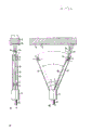
Describe a kind of preferential especially structure of the present invention in detail according to Fig. 9 to 13 below.
According to Figure 9 shows that a longitudinal extension assembly, this assembly is only represented its breaking part with open position U, though the assembly of its continuous longitudinal extension being made up of following part in fact;
Pressure medium input pipe 12 is upright steel pipes, and parallel with the control valve of equally also making 31 up to the part at clutch 11 places from stretching, and this two pipe is welded by connecting dividing plate 36 by steel pipe in order to the joint location 1b that connects a pressure medium pipeline.Interior support at the steel pipe of control valve 31 axis of rotation 102, this end of expressing on the left side of Fig. 9 is driven by a hydraulic motor 101, it links to each other with an eccentric part as drive train 32 in the other end that the free end of control valve 31 stretches out, when axle 102 centered on its rotational, connector 103 was by doing the circular orbit motion with the eccentric part of crank mode effect.Also drive the connector 1c on the free end that is carried at flexible swing pipe 30 together, swing pipe 30 or even expansive, that is to say that it is pliable and tough HD-flexible pipe to a certain extent, make the shower nozzle 3 that removably is tightened on the connector 1c can realize a kind of circus movement with the rotation of axle 102.The pressure medium jets 5b that shower nozzle 3 ejects
1, 5b
2Skim over corresponding circuit orbit, as will further specifying by Figure 13.Motor 101 can with frequency range 1500-10000 rev/min just 25 and about 167 hertz between driving shaft 102 and shower nozzle 3.
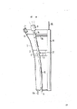
It in Figure 10 the phantom at X among Fig. 9-X place, the side column 6a of arc guiding device 6 props up control valve 31 both sides of axle 102 and stretches towards inside, two post 6a couple together by web 6b in bottom, so just can additionally guide a circle or oval-shaped tracks as the HD-flexible pipe of swing pipe 30.The free end of side column 6a is welded on the side of shelf 100, and shelf 100 is used to accept sensing element 35 and a lead 35a who leads to this sensing element.For can starting contactor when surperficial when one of bump; sensing element 35 can be done axially-movable in shelf 100; yet; this sensing element 35 can also be rigidly connected with the shelf 100 of a plug shape; under each situation; sensing element 35 all should surmount before shower nozzle 3 side, protracted at vertical LR of the longitudinal extension device of doctor-like, can protect the front end face of shower nozzle 3 before striking solid objects.This guiding device 6 that almost surrounds at the HD-flexible pipe 30 of " swing " on the circuit orbit should keep a free space between the side column 6a that links each other, like this, HD-flexible pipe 30 just can not be obstructed on its tracks, and this tracks is to be caused by the drive unit 32 that constitutes as eccentric part.That is to say and amazingly be, the HD-flexible pipe is based on using elastomeric material (as rubber, when by pressure medium in addition allow it that certain expansion is arranged) and structure flexible and that expand is a little even arranged, can make it to make the sort of swing as simply illustrating at Figure 12, therefore, at fixed point A corresponding to the clutch among Fig. 9 11, HD-flexible pipe 30 remains static, the outer end D that it is fixed with shower nozzle 3 then realizes an oscillating movement back and forth in this plan, yet in fact, as being illustrated by Figure 13, in such plane, realized a circular motion, this plane is actual to be perpendicular to or to be orthogonal to nozzle-axis.Different with the position that Figure 11 illustrates, wherein only HD-flexible pipe 30 moves on circuit orbit around the center of a supposition with the outer end that shower nozzle 3 links, different positions, as (in fact the position of 30 ") expression has produced the wave crest point E of standing wave and the nodal point B and the C of F and standing wave with solid line, broken broken line (30 ') and chain-dotted line.The hose movement of this " fluctuation shape " is not wish at present, and a good rock is processed or the rock cutting rate is very favorable to reaching.In the excessive skew of antinodal point E, F place flexible pipe, just excessive amplitude can be avoided by guiding device 6.Therefore, this guiding device 6 and be designed to the drive unit 32 and the clutch 103 thereof of eccentric part as HD-flexible pipe 30 can be in order to control described cutting rate in conjunction with HD-hose material and the pressure that flows through pressure medium wherein.
Utilizing as far as possible, the pressure medium of high pressure is more favourable.Suitable pressure limit is the 1500-2500 crust.
In addition, according to the material that will process or cut, in conjunction with the motion of shower nozzle 3, the structure that changes shower nozzle 3 is to regulate a kind of measure of its optimum condition.
According to a special structure of the present invention, an intermediate noxzzle is housed shower nozzle 3 and two side nozzles are proper.This intermediate noxzzle vertically or axially ejects a medium jet 5b shower nozzle 3
2, and side jet 5b
1, 5b
3Jet offsets and is approximately 20 ° drift angle thus.Jet 5b
1, 5b
2And 5b
3Basically be on the surface that point-like impinges upon rock 15 or the flute profile that has formed " mills out the hole " on 16.When shower nozzle 3 is in so-called circus movement state, be directed at the round K that the broken broken line among Figure 13 is represented
1, K
2, K
3Jet 5b
1, 5b
2, 5b
3Impingement position to be approximately the frequency run between 25 to 167 hertz, like this, the material of rock 15 is just directly hit down, so as according to jet the width c on inswept total surface from rock 15, mill out groove 16.What work especially is that this installs in the motion process that advances by direction of arrow Y shown in Figure 13, adjacent on the one hand round K
1/ K
2Between produced overlay region ü 1/2, between adjacent round K/K, overlap regional ü 2/3 on the other hand, and edge region, just the edge of groove 16 this overlapping phenomenon can not occur.When the front end of shower nozzle 3 and by jet 5b
1, 5b
2, 5b
3The distance between the surface of inswept rock 15 when being approximately 1-2cm, utilize such three shower nozzles, at pressure of pressure medium is that 2000 crust and frequency are under the condition of 50Hz, cutting rate to the sandstone rock can reach 15 square metres/hour, and the cutting rate of granite can reach unexpected 3 square metres of/hour such high cutting rates.In this respect, by the pressure medium that water constitutes, middle jet 5b
2Flow rate be 8 liters/minute, side jet 5b
1, 5b
3Has 14 liters/minute bigger flow rate, particularly point out, this high cutting rate is only being used flexible high-pressure hose as the connector before swing pipe 30 and the input pipe 12 at shower nozzle 3 and substantially rigid, and utilize simultaneously be only under the condition of eccentric part as drive train 32 possible.Clearly, motion is folded mutually, and this motion is caused by eccentric part on the one hand, on the other hand because due to the flexible and pliability of high-pressure hose, last even because the compression shock of pressure medium itself produces, this compression shock is by a high-pressure pump generation that does not illustrate.
The replacement device of Fig. 9 device is shown in Figure 14 and 15.At this, as eccentric element or drive train 32 is not a crank element, but bend to about 10 °-25 jiaos axle head spare 102a towards the longitudinal axis of axle 102, be with and fix a sleeve as eccentric part or drive train 32 on axle head spare 102a, this sleeve is fixedly linked through a rigid arm and a connector 1c as connector 103.Shower nozzle 3 is not shown in Figure 15.Axle 102 is at pipe of control valve 31() the end supporting with a bearing 31b, like this, shaft end 102a just can wind the axis of rotation rotation of being determined by bearing 31b, and owing to angle η just gives connector 1c and 3 one kinds of oscillating motions of shower nozzle.
Non-rotatably fix a radially upright arm 11a on clutch 11, this arm acts on the brake component 31a who is positioned on the control valve 31, thereby the screw thread that prevents clutch 11 is loose or get loose fully when 30 vibrations of HD flexible pipe or oscillating motion.
In the present invention, the possibility that arrangement provides other variations that is connected of connector 1c and eccentric.If flexible high-pressure hose 30 another one partly be mounted to " additional " swing pipe between connector 1c and shower nozzle 3, so, the motion of the whip dynamic formula of shower nozzle also will be strengthened.Rapidoprint applied alternation machinery can improve with stress hydraulic pressure.
This device not only in the open the quarry be used for rock 15 cutting and/boring, can also be used for mine, for example look for salt or at colliery layer broken coal or even in order to expansion ore bed passage, so that can better improve the passage that reaches inaccessible ore bed at salt deposit.Use apparatus of the present invention also can realize for example driving of underground traffic road of tunnel, in addition, can also clean runway, wall and similar item, remove road signal coloration, cleaning oil container or power plant tank, perhaps clean the ship wall under the water line, shell and sea bubble trace, perhaps alligatoring pavement of road to remove.To this, other purposes will be left the technician for and go to consider.
Claims (12)
1, utilize pressure medium to rock, ore, natural rock, materials such as concrete cut, the device of boring or similar processing, pressure medium is through delivering to a shower nozzle as the input pipe of flexible swing pipe, and become in an angle of oscillation jet that points on rock or the similar substance by at least one nozzle, it is characterized in that drive train (32,33) act on the flexible and expandable swing pipe (30), this drive train is bearing on the rigidity control valve (31), control valve (31) is parallel to input pipe (12) or injection direction stretches, control valve (31) will encourage the energy carrier of drive train (32) to be transmitted to drive train (32), also have a guiding device (6) that is used for swing pipe (30), and this swing pipe (30) is driven on transverse to jet direction with shower nozzle (3).
2, according to the device of claim 1, it is characterized in that shower nozzle (3) is equipped with two nozzles (5a) at least, shower nozzle (3) is hinged on the eccentric part as drive unit (32), and this eccentric part makes shower nozzle (3) do to move on circular or the oval-shaped track in perpendicular to the plane of swing tubular axis.
3, according to the device of claim 1 or 2, it is characterized in that shower nozzle (3) is configured in the free end of the swing pipe (30) as flexible high-pressure hose, high-pressure hose is that tartan is made, it can expand under the internal pressure effect.
4, according to the device of claim 1, it is characterized in that this eccentric part is bearing in the end of control valve (31), and utilizing an axle (102) as energy carrier, the kinetic energy that axle (102) will be configured in motor (101) generation of control valve (31) other end is delivered on the eccentric part with the form that rotatablely moves.
5,, it is characterized in that a rigidity input pipe (12) that leads to high-pressure hose (30) links to each other with control valve (31) through connecting dividing plate (36), and form longitudinally extending, a smooth member whereby according to the device of claim 4.
6, install according to claim 3, the part that it is characterized in that the swing pipe as high-pressure hose (30) of close shower nozzle (3) is directed in an arc guiding device (6), each side column (6a) of this guiding device is connected with a control valve (31) and/or a shelf (100), and the adjacent shower nozzle side partly that is separated by and surrounds shower nozzle (3) or swing pipe (30).
7, according to the device of claim 1, it is characterized in that tightening an intrinsic shelf (100) at control valve (31), this shelf is gone up to extend at vertical (LR) of device and is surmounted shower nozzle (3) side before.
8, according to the device of claim 3, it is characterized in that selected internal diameter as swing pipe (30) high-pressure hose should be obviously greater than the internal diameter of the input pipe (12) of rigidity.
9, according to the device of claim 3, the configuration, configuration and the size that it is characterized in that high-pressure hose (30), must when driving, eccentric element can make high-pressure hose realize a kind of inherent deformation of the shape that fluctuates at shower nozzle (3), and shower nozzle (3) be supported make it motion except that can regulating by eccentric element, fluctuation shape inherent deformation that can also high-pressure hose (30) is regulated.
10, according to the device of claim 1, it is characterized in that shower nozzle (3) removably is tightened on or is inserted on the STATEMENT OF FEDERALLY SPONSORED (1c), this STATEMENT OF FEDERALLY SPONSORED drives with eccentric part by a connector (103) and connects.
11, according to the device of claim 1, it is characterized in that shower nozzle (3) is equipped with an intermediate noxzzle (5a) and at least one pair of side nozzle (5a), each in two side nozzles all produces the side direction inclination jet (5b, 5b) biasing and become drift angle β with this jet direction of a middle jet (5b) of emerging at intermediate noxzzle (5a).
12,, it is characterized in that drift angle β is 15 ° to 30 ° according to the device of claim 11.
Applications Claiming Priority (4)
| Application Number | Priority Date | Filing Date | Title |
|---|---|---|---|
| DE3726733 | 1987-08-11 | ||
| DEP3726733,7 | 1987-08-11 | ||
| DEP3739825.3 | 1987-11-24 | ||
| DE19873739825 DE3739825A1 (en) | 1987-08-11 | 1987-11-24 | DEVICE FOR CUTTING, DRILLING OR SIMILAR WORKING ON STONE, ORE, CONCRETE OR THE LIKE |
Publications (2)
| Publication Number | Publication Date |
|---|---|
| CN1031743A CN1031743A (en) | 1989-03-15 |
| CN1017507B true CN1017507B (en) | 1992-07-22 |
Family
ID=25858525
Family Applications (1)
| Application Number | Title | Priority Date | Filing Date |
|---|---|---|---|
| CN88106530A Expired CN1017507B (en) | 1987-08-11 | 1988-08-10 | Apparatus for cutting, drilling or similar machining stone. ores or similars |
Country Status (10)
| Country | Link |
|---|---|
| US (1) | US4960176A (en) |
| EP (2) | EP0362292B1 (en) |
| CN (1) | CN1017507B (en) |
| AU (1) | AU608631B2 (en) |
| BR (1) | BR8807442A (en) |
| DE (2) | DE3739825A1 (en) |
| ES (1) | ES2030158T3 (en) |
| GR (1) | GR3004405T3 (en) |
| PT (1) | PT88223B (en) |
| WO (1) | WO1989001396A1 (en) |
Cited By (1)
| Publication number | Priority date | Publication date | Assignee | Title |
|---|---|---|---|---|
| CN101338650B (en) * | 2008-08-07 | 2011-03-16 | 中国人民解放军理工大学工程兵工程学院 | Pre-mixed abrasive high pressure water-jet boring device |
Families Citing this family (17)
| Publication number | Priority date | Publication date | Assignee | Title |
|---|---|---|---|---|
| DE3915933C1 (en) * | 1989-05-16 | 1990-11-29 | Schneider, Geb. Loegel, Francine, Ingwiller, Fr | |
| CA2064205C (en) * | 1989-07-21 | 1997-04-29 | Christopher Lyndon Higgins | Method and apparatus for cutting erosive materials using high pressure water means |
| US5371347A (en) * | 1991-10-15 | 1994-12-06 | Gap Technologies, Incorporated | Electro-optical scanning system with gyrating scan head |
| DE4128422C2 (en) * | 1991-08-27 | 1994-04-21 | Schneider Geb Loegel | Device and use of the device for removing material |
| NO174401C (en) * | 1992-01-17 | 1994-04-27 | Jan Kaare Hatloe | Equipment for cleaning rocks and other surfaces for rocks and other materials using high pressure water jets |
| SE501639C2 (en) * | 1993-08-17 | 1995-04-03 | Ulf Ekeblom | Device for controlling spray nozzle |
| US5363927A (en) * | 1993-09-27 | 1994-11-15 | Frank Robert C | Apparatus and method for hydraulic drilling |
| DE10233019B4 (en) * | 2002-07-20 | 2004-09-16 | Hochtief Ag | Soil mining method and apparatus for carrying out the method |
| AU2008209308B2 (en) * | 2007-01-25 | 2014-05-29 | Cmte Development Limited | Rock sampling apparatus |
| DE102007032772A1 (en) * | 2007-07-13 | 2009-01-15 | Jäger, Anton | Device for ejection of brake fluid consists of fluid feed and nozzle system where the ejected fluid flows |
| KR20120034545A (en) * | 2010-10-01 | 2012-04-12 | 한국과학기술원 | Blasting structure that have blasting pattern that minimize tunnel blasting perforation |
| CN104196450A (en) * | 2014-08-25 | 2014-12-10 | 江苏长城石油装备制造有限公司 | Improved drilling tool for soft geological layer reinforcement |
| EP3251795A1 (en) * | 2016-06-02 | 2017-12-06 | Leis Betontrennung GmbH & Co. KG | Apparatus and method for working on mineral workpieces, surfaces and/or structure sections |
| EP3589464B1 (en) * | 2017-11-30 | 2021-03-03 | LISEC Austria GmbH | Device for cutting plates |
| CN111577190A (en) * | 2020-04-23 | 2020-08-25 | 王水波 | Oil well foreign matter active protection type fishing equipment |
| CN112339140B (en) * | 2020-10-12 | 2022-09-16 | 泰州市津达电子科技有限公司 | Embedded road sign erection equipment of marble |
| US11708736B1 (en) * | 2022-01-31 | 2023-07-25 | Saudi Arabian Oil Company | Cutting wellhead gate valve by water jetting |
Family Cites Families (14)
| Publication number | Priority date | Publication date | Assignee | Title |
|---|---|---|---|---|
| US671429A (en) * | 1898-06-14 | 1901-04-09 | Bacon Air Lift Company | Process of making or improving wells. |
| GB718735A (en) * | 1952-04-30 | 1954-11-17 | Victor Donald Grant | Liquid-discharge nozzles |
| FR1257707A (en) * | 1960-02-22 | 1961-04-07 | Advanced spray device | |
| US3199615A (en) * | 1963-03-18 | 1965-08-10 | Lynn W Storm | Apparatus for maintaining a vertical well bore while drilling |
| GB1460711A (en) * | 1972-12-02 | 1977-01-06 | Pressure Dynamics Ltd | Liquid jet-cutting of materials |
| CH566173A5 (en) * | 1973-06-04 | 1975-09-15 | Aeromatic Ag | |
| DE2607097C2 (en) * | 1976-02-21 | 1984-09-13 | Wolfgang 4224 Hünxe Maasberg | Device for cleaning surfaces, in particular metal surfaces, surfaces of structures or the like. |
| NL7901909A (en) * | 1979-03-09 | 1980-09-11 | Ferro Bv | Rotatable coupling for controlled movement spray gun - has rotatable shaft contg. ducts registering with radial connections in fixed bush |
| GB2027776A (en) * | 1979-08-09 | 1980-02-27 | Gutehoffnungshuette Sterkrade | Cutting a Solid Body |
| US4369850B2 (en) * | 1980-07-28 | 1989-06-06 | High pressure fluid jet cutting and drilling apparatus | |
| DE3516572A1 (en) * | 1984-03-16 | 1986-11-20 | Charles Lichtenberg Loegel jun. | Improved device for cutting rock and further uses thereof |
| DE3410981C1 (en) * | 1984-03-16 | 1985-05-09 | Charles Ingwiller Loegel jun. | Method and device for cutting rock |
| DE3416514A1 (en) * | 1984-05-04 | 1985-11-07 | Otto 2000 Hamburg Frühling | Pipe-driving machine of inaccessible diameter |
| DE3422311C1 (en) * | 1984-06-15 | 1986-01-02 | M.A.N. Maschinenfabrik Augsburg-Nürnberg AG, 4200 Oberhausen | Tool, in particular a cutting head, for the hydro-mechanical winning of mineral raw materials or bituminous materials |
-
1987
- 1987-11-24 DE DE19873739825 patent/DE3739825A1/en active Granted
-
1988
- 1988-07-05 ES ES198888201560T patent/ES2030158T3/en not_active Expired - Lifetime
- 1988-07-05 EP EP88905802A patent/EP0362292B1/en not_active Expired - Lifetime
- 1988-07-05 DE DE8888905802T patent/DE3861969D1/en not_active Expired - Fee Related
- 1988-07-05 BR BR888807442A patent/BR8807442A/en not_active IP Right Cessation
- 1988-07-05 WO PCT/EP1988/000593 patent/WO1989001396A1/en active IP Right Grant
- 1988-07-05 EP EP88201560A patent/EP0303313B1/en not_active Expired - Lifetime
- 1988-07-05 AU AU19966/88A patent/AU608631B2/en not_active Ceased
- 1988-07-05 US US07/411,531 patent/US4960176A/en not_active Expired - Fee Related
- 1988-08-09 PT PT88223A patent/PT88223B/en not_active IP Right Cessation
- 1988-08-10 CN CN88106530A patent/CN1017507B/en not_active Expired
-
1992
- 1992-04-17 GR GR920400747T patent/GR3004405T3/el unknown
Cited By (1)
| Publication number | Priority date | Publication date | Assignee | Title |
|---|---|---|---|---|
| CN101338650B (en) * | 2008-08-07 | 2011-03-16 | 中国人民解放军理工大学工程兵工程学院 | Pre-mixed abrasive high pressure water-jet boring device |
Also Published As
| Publication number | Publication date |
|---|---|
| GR3004405T3 (en) | 1993-03-31 |
| ES2030158T3 (en) | 1992-10-16 |
| EP0303313B1 (en) | 1992-02-12 |
| PT88223A (en) | 1989-06-30 |
| PT88223B (en) | 1993-09-30 |
| DE3739825A1 (en) | 1989-02-23 |
| BR8807442A (en) | 1990-05-15 |
| DE3861969D1 (en) | 1991-04-11 |
| EP0362292B1 (en) | 1991-03-06 |
| AU1996688A (en) | 1989-03-09 |
| CN1031743A (en) | 1989-03-15 |
| WO1989001396A1 (en) | 1989-02-23 |
| EP0362292A1 (en) | 1990-04-11 |
| DE3739825C2 (en) | 1990-08-30 |
| EP0303313A1 (en) | 1989-02-15 |
| AU608631B2 (en) | 1991-04-11 |
| US4960176A (en) | 1990-10-02 |
Similar Documents
| Publication | Publication Date | Title |
|---|---|---|
| CN1017507B (en) | Apparatus for cutting, drilling or similar machining stone. ores or similars | |
| EP3656977B1 (en) | Cutter head for mining machine | |
| CN101575973B (en) | Mining machine with driven disc cutters | |
| US9022484B2 (en) | Material handling system for mining machine | |
| US4848486A (en) | Method and apparatus for transversely boring the earthen formation surrounding a well to increase the yield thereof | |
| NO333751B1 (en) | Drill bit | |
| US20110181097A1 (en) | Mining machine with driven disc cutters | |
| CS266311B2 (en) | Hole device | |
| CN1806087A (en) | Percussive drill bit | |
| JPS611794A (en) | Method and apparatus for crushing rock | |
| CN103382840A (en) | Punch-cutting mining method and punch-cutting mining machine implementing method | |
| JP2010043404A (en) | Drilling method, drilling machine, and drilling device | |
| CN1193160C (en) | Drilling apparatus for drilling well in stratum | |
| US5297639A (en) | Method and apparatus for using multiple jets | |
| CN109267931A (en) | A kind of device for lithostratigraphy slotting | |
| CN212202041U (en) | Novel coal mine tunneling and mining device | |
| US3033543A (en) | Sonic method and apparatus for surface mining mineral beds or the like | |
| CN110185446A (en) | Purposes by impact drill and cutter combination for mining | |
| RU2030540C1 (en) | Cutting-shearing type drilling bit | |
| US7562726B2 (en) | Device for drilling a bore in the ground | |
| SU1162933A1 (en) | Hydromechanical bit for drilling wells | |
| EP0119268A1 (en) | Hydrojet drilling means and method | |
| KR19980072547A (en) | Quarry Water Jet Slotter | |
| RU2193628C2 (en) | Horizontal drilling machine | |
| NO168236B (en) | DEVICE FOR CUTTING, DRILLING AND SIMILAR WORKING STONE, ORE, CONCRETE OR SIMILAR. |
Legal Events
| Date | Code | Title | Description |
|---|---|---|---|
| C06 | Publication | ||
| PB01 | Publication | ||
| C10 | Entry into substantive examination | ||
| SE01 | Entry into force of request for substantive examination | ||
| C13 | Decision | ||
| GR02 | Examined patent application | ||
| C14 | Grant of patent or utility model | ||
| GR01 | Patent grant | ||
| C19 | Lapse of patent right due to non-payment of the annual fee | ||
| CF01 | Termination of patent right due to non-payment of annual fee |