The application is to be on June 21st, 2007 applying date, and application number is 200780000984.1, and the application people is a Panasonic Electric Equipment Industrial Co.,Ltd, and denomination of invention is the dividing an application in first to file of " fuel cell ".
Embodiment
Fuel cell of the present invention has a cell of fuel cell at least.That is to say that fuel cell of the present invention both can be the cell of fuel cell monomer, also can be the fuel cell stack with a plurality of unit.Usually, cell of fuel cell or storehouse be by collector plate, insulation board and end plate clamping, and fix through connecting rod.
Cell of fuel cell comprises: the separator of a pair of catalysis electrode of polyelectrolyte membrane, clamping polyelectrolyte membrane (fuel electrodes and air pole) and clamping MEA (aggregate of polyelectrolyte membrane and catalysis electrode).Catalysis electrode is made up of Catalytic Layer that is positioned at the polyelectrolyte membrane side and the gas diffusion layers that is positioned at the separator side.
Polyelectrolyte membrane is the polymeric membrane with hydrogen.The material of polyelectrolyte membrane does not have special qualification so long as the material that hydrogen ion is moved gets final product.
Catalytic Layer is the layer that contains for the catalyst of the redox reaction of hydrogen or oxygen.Catalytic Layer does not have special qualification so long as have conductivity and the layer that has the catalytic action of the oxidation reaction of hydrogen or oxygen gets final product.
Gas diffusion layers is the porous layer with conductivity.The material of gas diffusion layers does not have special qualification so long as have conductivity and material that reacting gas can spread gets final product.Gas diffusion layers also can constitute to the gas diffusion substrate layer of Catalytic Layer diffusion and the carbon coating of the contact between raising gas diffusion substrate layer and the Catalytic Layer by making from separator side gas supplied.
Separator be with face that fuel electrodes contacts on have fuel gas channel and with face that air pole contacts on have the conductivity of oxidizing gas stream plate.Example as the separator material comprises carbon or metal etc.Comprise recess and protuberance on the face with gas flow path of separator, recess forms gas flow path.
Separator also can be, the raw meal of having mixed carbon dust and resinoid bond is supplied with mould and the raw meal of supplying with mould is exerted pressure and heat and the device that forms (below, be called " carbon separation unit ").For example, open the carbon separation unit of recording and narrating in the 2000-243409 communique (Japan) spy.
And separator also can be made up of (below, be called " apparatus for separating metals ") metallic plate.For example, open the 2003-203644 communique (Japan) spy and open the apparatus for separating metals of recording and narrating in the 2005-276637 communique with (Japan) spy.
The metallic plate that constitutes apparatus for separating metals has the surface and the back side.Metallic plate can be recess protuberance with the recess at the back side of this part corresponding metallic plate corresponding and surperficial with the protuberance at the back side of this part on surface.The method that on metallic plate, forms reaction gas flow paths does not have special qualification.For example, the method for formation reaction gas flow paths is a punch process on metallic plate.
The material of metallic plate does not have special qualification so long as have good electrical conductivity and the material of corrosion resistance gets final product.Example as metallic sheet material comprises stainless steel.As long as the thickness of metallic plate has the intensity that forms separator, do not have special qualification.For example, the thickness of metallic plate is 0.01mm~1mm.The size of apparatus for separating metals needs only ability clamping MEA, does not have special qualification, suitably sets to get final product.
Through using apparatus for separating metals, even the thickness of separator also can obtain enough intensity below 1mm.Thus, the miniaturization of unit and storehouse and lightweight become possibility.And, can easily make apparatus for separating metals through punch process etc., thus can cutting down cost and a large amount of production.
Reaction gas flow paths in the separator forms by following mode: near the stream the inlet of gas flow path (below; Be called " upstream flow path ") and the outlet of gas flow path near stream (below; Be called " downstream flow path ") adjacent in one side, and can be to whole supply response gas of catalysis electrode.The wall of reaction gas flow paths forms the permeability with reacting gas.Here, " wall of reaction gas flow paths " is meant the protuberance of the separator between two adjacent reaction gas flow paths.For whole supply response gas, for example, form tortuous shape or Vorticose reaction gas flow paths gets final product to catalysis electrode.In addition, do not need the upstream flow path of same gas flow path and downstream flow path adjacent, can make the downstream flow path of upstream flow path and second gas flow path of first gas flow path adjacent yet.At the thickness of gas diffusion layers is that the width of 200 μ m~300 μ m and stream is that the degree of depth of 1.1mm, stream is under the situation of 1.1mm, between upstream flow path and the downstream flow path be spaced apart 2.2mm~3.3mm the time, the generating efficiency of cell of fuel cell is the highest.Therefore, be that the width of 200 μ m~300 μ m and stream is that the degree of depth of 1.1mm, stream is under the situation of 1.1mm preferably at the thickness of gas diffusion layers, be spaced apart 2.2mm~3.3mm between upstream flow path and the downstream flow path.The example of the flow passage structure of reaction gas flow paths is as shown in Figure 3.
In the example shown in Fig. 3 A; The reaction gas flow paths 102 that on separator 100, forms is the following round stream that forms; Promptly; To the enter the mouth reacting gas forward stream 104 of 108 sides and come and go stream fold back portion 112 certainly to the configuration relatively on overall flow paths of the reverse stream 106 of the reacting gas of flowing path outlet 110 sides of stream, and reaction gas flow paths 102 is keeping the adjacent state of forward stream 104 and the reverse stream 106 tortuous shape of formation down from round stream fold back portion 112.Here, " relatively configuration " is meant that the flow direction of reacting gas of adjacent and two streams of two streams is opposite.Like this, preferably, reaction gas flow paths forms by following mode, and near the not only configuration relatively of the stream (upstream flow path and downstream flow path) the reaction gas flow paths gateway is in all configurations relatively of overall flow paths.In addition, preferably, stream inlet 108 and flowing path outlet 110 are adjacent one another are.
In the example shown in Fig. 3 B, reaction gas flow paths 102 is round streams identical with the example shown in Fig. 3 A, and is keeping the adjacent state of the reverse stream of reacting gas forward stream 104 and reacting gas 106 formation vortex shape down.
Example shown in Fig. 3 C is for being formed with the example of two reaction gas flow paths 102a and 102b in separator 100.Reaction gas flow paths 102a and reaction gas flow paths 102b dispose in overall flow paths relatively, and are keeping forming tortuous shape under the reaction gas flow paths 102a state adjacent with reaction gas flow paths 102b.
In fuel cell of the present invention, after the oxidizing gas that the fuel gas that will contain hydrogen offers the fuel gas channel in the separator and will contain carrier of oxygen offers the oxidizing gas stream,, can obtain electric energy through following reaction.
At first, the hydrogen molecule that offers fuel electrodes spreads in the gas diffusion layers of fuel electrodes and arrives Catalytic Layer.In Catalytic Layer, hydrogen molecule is divided into hydrogen ion and electronics.Hydrogen ion is through being moved to air pole by the polyelectrolyte membrane of humidification.Electronics moves to air pole through the external circuit.At this moment, can the electronics through the external circuit be utilized as electric energy.In the Catalytic Layer of air pole, move the hydrogen ion that comes through polyelectrolyte membrane and move electronics that comes and the oxygen that offers air pole through the external circuit and react generation water.
In fuel cell of the present invention, be adjacent to formation through upstream flow path and the downstream flow path that makes reaction gas flow paths, and carry out the water transport of direction in the cell of fuel cell inside face.Below, the water transport of direction in the face in the air pole side is described.
Because the cell of fuel cell in when generating is a high temperature, so the water that Catalytic Layer generated in air pole becomes steam during generating.This steam spreads in the gas diffusion layers of air pole and moves, and the oxidizing gas in the oxidizing gas stream is carried out humidification.Flow through the oxidizing gas stream oxidizing gas along with from the inlet advance to outlet, its steam partial pressure is enhanced.That is to say that the steam partial pressure of the oxidizing gas of the downstream flow path of the oxidizing gas stream of flowing through is higher than the steam partial pressure of the oxidizing gas of the adjacent upstream flow path of flowing through.Because this steam partial pressure is poor, the part of the steam of the downstream flow path of flowing through moves through the adjacent upstream flow path of gaseous diffusion course.As a result, moisture is from downstream flow path stream direction transfer in face upstream.
Like this, fuel cell of the present invention is through making upstream flow path and downstream flow path adjacent, and can reduce poor between the amount of moisture of reacting gas of the amount of moisture in the reacting gas of the upstream flow path of flowing through and the downstream flow path of flowing through.Thus, can realize: suppress too moistening near the polyelectrolyte membrane at the position of downstream flow path, and suppress drying near the polyelectrolyte membrane at the position of upstream flow path.That is to say, do not use fuel cell of the present invention, also can make the moisture distribution of direction in the inner face in unit even even do not carry out humidification (inner humidification method).
And in fuel cell of the present invention, reaction gas flow paths is kept the upstream flow path state adjacent with downstream flow path, forms tortuous shape or vortex shape simultaneously.Thus, can reduce the quantity of the manifold and the structural member of subsidiary this manifold, thereby can make the simple in structure of cell of fuel cell and fuel cell stack.In addition, can make gas flow path elongated,, thereby can carry out the water transport of direction in the face more expeditiously with compared with techniques in the past so the difference of the steam partial pressure between upstream flow path and the downstream flow path becomes big owing to make gas flow path become tortuous shape or vortex shape.
And, in fuel cell of the present invention, make the wall of reaction gas flow paths not have the permeability of reacting gas, so can suppress the circulation of the reacting gas between the stream.Thus, can expeditiously reacting gas be offered Catalytic Layer.
Below, with reference to accompanying drawing execution mode of the present invention is described at length.
(execution mode 1)
Fig. 4 is the profile of the cell of fuel cell of execution mode 1 of the present invention.
In Fig. 4, cell of fuel cell comprises: the pair of separated device (fuel electrodes separator 600 and air pole separator 700) of a pair of catalysis electrode of polyelectrolyte membrane 200, clamping polyelectrolyte membrane 200 (fuel electrodes 300 and air pole 400) and clamping MEA500 (aggregates of polyelectrolyte membrane 200 and catalysis electrode 300 and 400).Separator 600 and 700 material for example are carbon.Fuel electrodes separator 600 has fuel gas channel 614.Air pole separator 700 has oxidizing gas stream 714.Fuel electrodes 300 is made up of fuel electrodes Catalytic Layer 310 that is positioned at the polyelectrolyte membrane side and the fuel electrodes gas diffusion layers 320 that is positioned at fuel electrodes separator side.Equally, air pole 400 is made up of air pole Catalytic Layer 410 that is positioned at the polyelectrolyte membrane side and the air pole gas diffusion layers 420 that is positioned at air pole separator side.Fuel electrodes gas diffusion layers 320 also is made up of fuel electrodes carbon coating 330 that is positioned at fuel electrodes Catalytic Layer side and the fuel electrodes gas diffusion substrate layer 340 that is positioned at fuel electrodes separator side.Equally, air pole gas diffusion layers 420 is made up of air pole carbon coating 430 that is positioned at air pole Catalytic Layer side and the air pole gas diffusion substrate layer 440 that is positioned at air pole separator side.
Polyelectrolyte membrane 200, fuel electrodes Catalytic Layer 310, fuel electrodes carbon coating 330, fuel electrodes gas diffusion substrate layer 340, air pole Catalytic Layer 410, air pole carbon coating 430 and air pole gas diffusion substrate layer 440 use above-mentioned parts to get final product.
Fig. 5 is the front elevation of face of the fuel electrodes side of fuel electrodes separator 600 shown in Figure 4.
In Fig. 5, fuel electrodes separator 600 comprises: fuel gas supply manifold 610, fuel gas are discharged manifold 612, fuel gas channel 614, oxidizing gas supply manifold 630, oxidizing gas discharge manifold 632, cooling water supplies with manifold 640 and cooling water is discharged manifold 642.Fuel gas channel 614 is made up of fuel gas forward stream 618 till fuel gas supply manifold 610 to round stream fold back portion 616 and the reverse stream 620 of fuel gas till round stream fold back portion 616 to fuel gas discharge manifold 612.
Fuel gas supply manifold 610 is the holes that are used for fuel gas is offered each cell of fuel cell in the fuel cell stack, and fuel gas is offered fuel gas channel 614.
It is to be used for the hole that each cell of fuel cell in the fuel cell stack is discharged fuel gas that fuel gas is discharged manifold 612, and fuel gas is discharged from fuel gas channel 614.
Fuel gas channel 614 is streams of whole that the fuel gas of supplying with from fuel gas supply manifold 610 offered fuel electrodes 300, forms tortuous shape.And the reverse stream 620 of fuel gas forward stream 618 and fuel gas forms by mode opposite each other.The wall of fuel gas channel 614 forms the permeability with fuel gas.
It is the holes that are used for oxidizing gas is offered each cell of fuel cell in the fuel cell stack that oxidizing gas is supplied with manifold 630.And it is to be used for the hole that each cell of fuel cell in the fuel cell stack is discharged oxidizing gas that oxidizing gas is discharged manifold 632.
It is to be used for cooling water is offered the hole in the fuel cell stack that cooling water is supplied with manifold 640.And it is the holes that are used in fuel cell stack, discharging cooling water that cooling water is discharged manifold 642.Not shown cooling water stream is to be communicated with the stream that cooling water is supplied with manifold 640 and cooling water discharge manifold 642, for example is formed on fuel electrodes separator 600 or the air pole separator 700.For example; In fuel cell stack; In order to make the cooling water stream between fuel electrodes separator 600 and air pole separator 700, on the face of the reaction gas flow paths that does not form fuel electrodes separator 600 or air pole separator 700, form the cooling water stream and get final product.At this moment, can form the cooling water stream, also can form the cooling water stream every several unit to each unit.And the flow passage structure of cooling water is not particularly limited, and can be a plurality of parallel stream of linearity, also can be tortuous shape or vortex shape.
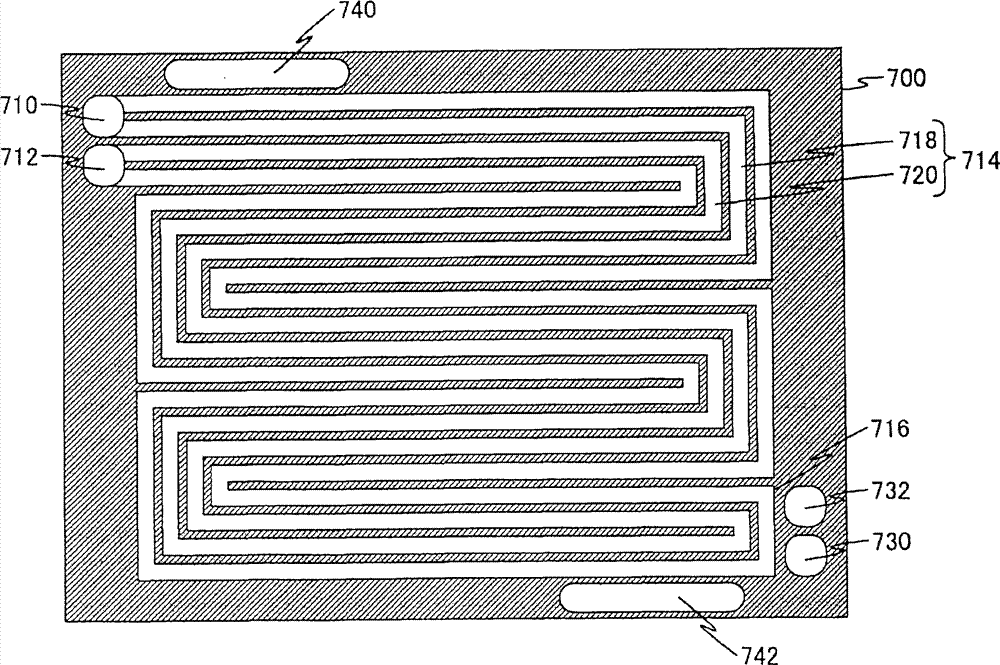
Fig. 6 is the front elevation of face of the air pole side of air pole separator 700 shown in Figure 4.
In Fig. 6, air pole separator 700 comprises: oxidizing gas is supplied with manifold 710, oxidizing gas is discharged manifold 712, oxidizing gas stream 714, fuel gas supply manifold 730, fuel gas discharge manifold 732, cooling water supply manifold 740 and cooling water and discharged manifold 742.Oxidizing gas stream 714 is made up of oxidizing gas forward stream 718 till oxidizing gas supply manifold 710 to round stream fold back portion 716 and the reverse stream 720 of oxidizing gas till round stream fold back portion 716 to oxidizing gas discharge manifold 712.
It is the holes that are used for oxidizing gas is offered each cell of fuel cell in the fuel cell stack that oxidizing gas is supplied with manifold 710, and oxidizing gas is offered oxidizing gas stream 714.Oxidizing gas is supplied with manifold 710 and is communicated with oxidizing gas supply manifold 630 shown in Figure 5.
It is to be used for the hole that each cell of fuel cell in the fuel cell stack is discharged oxidizing gas that oxidizing gas is discharged manifold 712, and oxidizing gas is discharged from oxidizing gas stream 714.Oxidizing gas is discharged manifold 712 and is communicated with oxidizing gas discharge manifold 632 shown in Figure 5.
Oxidizing gas stream 714 is that the oxidizing gas of supplying with manifold 710 supplies from oxidizing gas is offered whole stream of air pole 400, and forms tortuous shape.And the reverse stream 720 of oxidizing gas forward stream 718 and oxidizing gas forms by mode opposite each other.The wall of oxidizing gas stream 714 forms the permeability with oxidizing gas.And preferably, the width of oxidizing gas stream is that 1.1mm, the degree of depth are 1.1mm.And then, preferably, be spaced apart 2.2mm~3.3mm between downstream flow path (oxidizing gas is discharged near the oxidizing gas stream 714 the manifold 712) and the upstream flow path (oxidizing gas is supplied with near the oxidizing gas stream 714 of manifold 710).That is to say, preferably, 2 times~3 times of the width that is spaced apart oxidizing gas stream 714 between upstream flow path and the downstream flow path.
Fuel gas supply manifold 730 is the holes that are used for fuel gas is offered each cell of fuel cell in the fuel cell stack.Fuel gas supply manifold 730 is communicated with fuel gas supply manifold 610 shown in Figure 5.
It is to be used for the hole that each cell of fuel cell in the fuel cell stack is discharged fuel gas that fuel gas is discharged manifold 732.Fuel gas is discharged manifold 732 and is communicated with fuel gas discharge manifold 612 shown in Figure 5.
It is to be used for cooling water is offered the hole in the fuel cell stack that cooling water is supplied with manifold 740.Cooling water is supplied with manifold 740 and is communicated with cooling water supply manifold 640 shown in Figure 5.And it is the holes that are used in fuel cell stack, discharging cooling water that cooling water is discharged manifold 742.Cooling water is discharged manifold 742 and is communicated with cooling water discharge manifold 642 shown in Figure 5.
Below, the generating mechanism like the running in the cell of fuel cell of above-mentioned structure the time is described.
Fuel gas supply manifold 610 and 730 the fuel gas that offers cell of fuel cell is provided for the inner fuel gas channel 614 of fuel electrodes separator 600.Oxidizing gas in the fuel gas channel 614 moves to 310 diffusions of fuel electrodes Catalytic Layer through fuel electrodes gas diffusion layers 320.
On the other hand, offer the oxidizing gas supply manifold 630 of cell of fuel cell and 710 oxidizing gas and be provided for air pole separator 700 interior oxidation gas flow paths 714.Oxidizing gas in the oxidizing gas stream 714 moves to 410 diffusions of air pole Catalytic Layer through air pole diffusion layer 420.
In fuel electrodes Catalytic Layer 310, move the hydrogen molecule that fuel gas comprised that comes from fuel gas channel 614 and be divided into hydrogen ion and electronics.Hydrogen ion moves to 410 diffusions of air pole Catalytic Layer through the polyelectrolyte membrane 200 of water conservation.On the other hand, electronics moves to air pole Catalytic Layer 410 through not shown external circuit.
In air pole Catalytic Layer 410, move next hydrogen ion and move the electronics that comes through the external circuit and move the oxygen that comes from oxidizing gas stream 714 and react through polyelectrolyte membrane 200, generate water.
Because the cell of fuel cell during generating is a high temperature, so the water that generates becomes steam, this steam moves to 714 diffusions of oxidizing gas stream through air pole gas diffusion layers 420, thereby the oxidizing gas in the oxidizing gas stream 714 is carried out humidification.Along with oxidizing gas advances in oxidizing gas stream 714, its humidification amount increases.Therefore, the flow through dividing potential drop of the steam in the oxidizing gas of the reverse stream 720 of oxidizing gas is higher than the dividing potential drop of the steam in the oxidizing gas of the oxidizing gas forward stream 718 of configuration relatively of flowing through.It is obvious that the partial pressure difference of this steam particularly becomes between downstream flow path and upstream flow path.Because the partial pressure difference of this steam, the steam in the reverse stream 720 of oxidizing gas is through air pole gas diffusion layers 420, and direction is in the oxidizing gas forward stream 718 of configuration, moving in face.Thus, the dividing potential drop of the steam in the oxidizing gas stream 714 distributes and becomes even.
Also through identical effect, the steam in the reverse stream 620 of fuel gas is through fuel electrodes gas diffusion layers 320 in the fuel electrodes side, and direction moves in fuel gas forward stream 618 in face.
As stated, according to this execution mode, because the forward stream of reaction gas flow paths relatively forms in overall flow paths with reverse stream with disposing, so the dividing potential drop of the interior steam of reaction gas flow paths is evenly distributed.Therefore, according to this execution mode, can utilize cell of fuel cell expeditiously whole, thus can obtain higher power generation performance and power generation stabilization property.
And, have the permeability of reacting gas through the wall that does not make reaction gas flow paths, can suppress the circulation of the reacting gas between the stream.Thus, can expeditiously reacting gas be offered Catalytic Layer.
And then, according to this execution mode, because reaction gas flow paths forms tortuous shape, so even the negligible amounts of reaction gas flow paths and various manifolds, also can be to whole supply response gas of cell of fuel cell.Therefore, according to this execution mode,, also can not make the complex structure of unit and storehouse and obtain higher power generation performance and power generation stabilization property even increase the area of unit.
In addition, in this execution mode, the forward stream of reaction gas flow paths and the reverse stream separator that relative configuration ground forms in one side are applicable to fuel electrodes side and air pole side both sides, but also can be only applicable to generate the air pole side of steam.
In addition, in this execution mode, the quantity that is communicated with the gas flow path between a pair of manifold is made as two, but the quantity of gas flow path can be one, also can be more than three.
(execution mode 2)
In execution mode 2, illustrate and use the example of metal as the separator material.
The cell of fuel cell of execution mode 2 is that the air pole separator 700 in the cell of fuel cell of execution mode shown in Figure 41 is replaced with air pole separator 900, and fuel electrodes separator 600 is replaced with the unit of fuel electrodes separator 800 back gained.Therefore, to the inscape of air pole separator 900 and the repetition beyond the fuel electrodes separator 800, give identical label, and omit its explanation.
Fig. 7 is the profile of the cell of fuel cell of execution mode 2 of the present invention.To the inscape identical, give identical label, and omit the explanation of repetition part with the air pole separator 700 of execution mode 1 and fuel electrodes separator 600.
Apparatus for separating metals is made up of metallic plate in Fig. 7.The fuel electrodes separator has fuel gas channel 814.Air pole separator 900 has oxidizing gas stream 914.
The shape of oxidizing gas stream 914 and fuel gas channel 814 can be identical with oxidizing gas stream 714.That is to say that oxidizing gas stream 914 is that the oxidizing gas of supplying with the manifold supply from oxidizing gas is offered whole stream of air pole 400, and forms tortuous shape.The reverse stream of oxidizing gas forward stream and oxidizing gas forms by mode opposite each other.And fuel gas channel 814 is with offering whole stream of fuel electrodes 300 from fuel gas supply manifold gas supplied, and forms tortuous shape.The reverse stream of fuel gas forward stream and fuel gas forms by mode opposite each other.
Fig. 8 is the profile of the fuel cell stack that constitutes of the cell of fuel cell through range upon range of Fig. 7.
In Fig. 8, fuel cell stack constitutes with the composition metal separator 1000 that is made up of apparatus for separating metals 800 and apparatus for separating metals 900 through range upon range of MEA500 alternately.Fuel gas diffusion layer side at composition metal separator 1000 forms fuel gas channel 814, and forms oxidizing gas stream 914 in the oxidizing gas diffusion layer side of composition metal separator 1000.Space in apparatus for separating metals 1000 forms the cooling water stream.
When making like the action of the cell of fuel cell of above-mentioned structure, identical with the cell of fuel cell of execution mode 1, the dividing potential drop of the steam in the oxidizing gas stream distributes and becomes even.
And, because metallic plate does not have the permeability of reacting gas, so through using apparatus for separating metals can suppress the circulation of the reacting gas between the stream more.Thus, can reacting gas be offered the air pole Catalytic Layer expeditiously.
And then, even the thickness of metallic plate below 1mm, also shows enough intensity.Thus, the miniaturization of unit and storehouse and lightweight become possibility.And, can easily make apparatus for separating metals through punch process etc., thus can cutting down cost and a large amount of production.
(execution mode 3)
In execution mode 1, show the relative example that disposes of the forward stream that makes a stream with reverse stream.Two examples that different streams is opposite each other of execution mode 3 expressions.
The cell of fuel cell of execution mode 3 is the unit that the air pole separator 700 in the cell of fuel cell of execution mode shown in Figure 41 replaced with air pole separator 702 back gained.Therefore, to the inscape of the repetition beyond the air pole separator 702, give identical label, and omit its explanation.
Fig. 9 is the front elevation of face of air pole side of air pole separator of the fuel cell of embodiment of the present invention 3.To the inscape identical, give identical label, and omit the explanation of repetition part with the air pole separator of execution mode 1 700.
In Fig. 9, air pole separator 702 comprises: first oxidizing gas supply manifold 710a, second oxidizing gas supply manifold 710b, first oxidizing gas are discharged manifold 712a, second oxidizing gas is discharged manifold 712b, the first oxidizing gas stream 714a, the second oxidizing gas stream 714b, the first fuel gas supply manifold 730a, the second fuel gas supply manifold 730b, first fuel gas discharge manifold 732a, second fuel gas discharge manifold 732b, cooling water supply manifold 740 and cooling water and discharged manifold 742.
First oxidizing gas supplies with manifold 710a and second oxidizing gas supply manifold 710b is the hole that is used for oxidizing gas is offered each cell of fuel cell in the fuel cell stack.First oxidizing gas is supplied with manifold 710a oxidizing gas is offered the first oxidizing gas stream 714a.Equally, second oxidizing gas is supplied with manifold 710b oxidizing gas is offered the second oxidizing gas stream 714b.
First oxidizing gas is discharged manifold 712a and second oxidizing gas and is discharged manifold 712b and be used for the hole that each cell of fuel cell in the fuel cell stack is discharged oxidizing gas.First oxidizing gas is discharged manifold 712a and is discharged oxidizing gas from the first oxidizing gas stream 714a.Equally, second oxidizing gas is discharged manifold 712b and is discharged oxidizing gas from the second oxidizing gas stream 714b.
The first oxidizing gas stream 714a and the second oxidizing gas stream 714b will be offered the stream of 400 whole of air pole by the oxidizing gas that first oxidizing gas supply manifold 710a or second oxidizing gas supply manifold 710b supply with for being used for.The first oxidizing gas stream 714a supplies with manifold 710a with first oxidizing gas and first oxidizing gas discharge manifold 712a is communicated with.Equally, the second oxidizing gas stream 714b is communicated with second oxidizing gas supply manifold 710b and second oxidizing gas discharge manifold 712b.The first oxidizing gas stream 714a and the second oxidizing gas stream 714b be configuration relatively on the whole, and is keeping forming tortuous shape under the first oxidizing gas stream 714a state adjacent with the second oxidizing gas stream 714b.The wall of oxidizing gas stream (714a and 714b) forms the permeability with oxidizing gas.Preferably, be spaced apart 2.2mm~3.3mm between the upstream flow path of the downstream flow path of the interval between the downstream flow path of the upstream flow path of the first oxidizing gas stream 714a and the second oxidizing gas stream 714b or the first oxidizing gas stream 714a and the second oxidizing gas stream 714b.
The first fuel gas supply manifold 730a and the second fuel gas supply manifold 730b are the hole that is used for fuel gas is offered each cell of fuel cell in the fuel cell stack.And first fuel gas is discharged manifold 732a and the second fuel gas supply manifold 732b and is used for the hole that each cell of fuel cell in the fuel cell stack is discharged fuel gas.
When making like the action of the cell of fuel cell of above-mentioned structure, identical with the cell of fuel cell of execution mode 1, the dividing potential drop of the steam in the oxidizing gas stream distributes and becomes even.That is to say, the steam in the downstream flow path of the first oxidizing gas stream 714a in face direction in the upstream flow path of the second oxidizing gas stream 714b of configuration, moving.Equally, the steam in the downstream flow path of the second oxidizing gas stream 714b in face direction in the upstream flow path of the first oxidizing gas stream 714a of configuration, moving.
As stated,, except the effect of execution mode 1, the oxidizing gas stream can also be in the cell of fuel cell face, formed symmetrically, thereby the dividing potential drop more even distribution of the steam in the oxidizing gas stream can be made according to this execution mode.Therefore, can utilize cell of fuel cell more expeditiously whole, thus can obtain higher power generation performance and power generation stabilization property.
And, according to this execution mode, except the effect of execution mode 1, the length of oxidizing gas stream is shortened, supply with the reaction gas pressure in the manifold thereby can reduce oxidizing gas.Therefore, the load of the air blast of supplying with oxidizing gas can be reduced, thereby the whole generating efficiency of electricity generation system can be improved more.
And, in this execution mode, the flow passage structure of air pole side only has been described, but the flow passage structure of fuel electrodes side also can be the structure identical with the flow passage structure of air pole side.At this moment, in the fuel electrodes side, also can make the dividing potential drop more even distribution of the moisture distribution of direction in the face.
(execution mode 4)
In execution mode 1~3, the area of section that shows reaction gas flow paths is at the upstream flow path example identical with downstream flow path.In execution mode 4, the area of section that reaction gas flow paths is shown is at the upstream flow path example different with downstream flow path.
The fuel cell of execution mode 4 is the fuel cells that the air pole separator 700 in the fuel cell of execution mode shown in Figure 41 replaced with air pole separator 704 back gained.Therefore, to the inscape of the repetition beyond the air pole separator 704, give identical label, and omit its explanation.
Figure 10 is the front elevation of face of air pole side of air pole separator of the cell of fuel cell of embodiment of the present invention 4.To the inscape identical, give identical label, and omit the explanation of repetition part with the air pole separator of execution mode 3 702.
In Figure 10, air pole separator 704 comprises: first oxidizing gas supply manifold 710a, second oxidizing gas supply manifold 710b, first oxidizing gas are discharged manifold 712a, second oxidizing gas is discharged manifold 712b, the first oxidizing gas stream 714a, the second oxidizing gas stream 714b, the first fuel gas supply manifold 730a, the second fuel gas supply manifold 730b, first fuel gas discharge manifold 732a, second fuel gas discharge manifold 732b, cooling water supply manifold 740 and cooling water and discharged manifold 742.
The first oxidizing gas stream 714a and the second oxidizing gas stream 714b and execution mode 3 identical configurations relatively on the whole, and keeping forming tortuous shape under the first oxidizing gas stream 714a state adjacent with the second oxidizing gas stream 714b.And then the first oxidizing gas stream 714a and the second oxidizing gas stream 714b form by the mode that the width of downstream stream is narrower than the width of upstream flow path.Also can make said width step-like ground or diminish gradually from the upstream flow path to the downstream flow path.The wall of oxidizing gas stream (714a and 714b) also forms the permeability with oxidizing gas.
When making like the action of the cell of fuel cell of above-mentioned structure, identical with the cell of fuel cell of execution mode 3, the dividing potential drop distribution of the steam in oxidizing gas stream 714a and the 714b becomes even.In addition, because the area of section of the downstream flow path of oxidizing gas stream 714a and 714b is less than the area of section of upstream flow path, so can suppress the minimizing with the oxidizing gas dividing potential drop that consumption produced of oxidizing gas.Thus, oxidizing gas does not move on the direction in face, and the distribution of the dividing potential drop of the oxidizing gas in oxidizing gas stream 714a and the 714b becomes even.
As stated; According to this execution mode; Except the effect of execution mode 1~3; Can also make the oxidizing gas dividing potential drop of oxidizing gas stream upstream flow path be lower than the oxidizing gas dividing potential drop of downstream flow path, thus the oxidizing gas that can prevent upstream flow path through the air pole gas diffusion layers downstream stream move.Thus, can reacting gas be offered the air pole Catalytic Layer expeditiously, thereby can improve generating efficiency more.
In addition, in this execution mode, adjust the area of section of reaction gas flow paths, but also can adjust the area of section of gas flow path through the degree of depth that changes stream through the width that changes reaction gas flow paths.
And, in this execution mode, the flow passage structure of air pole side only has been described, but the flow passage structure of fuel electrodes side also can be the structure identical with the flow passage structure of air pole side.At this moment, also can make the moisture distribution of direction in the face and the dividing potential drop more even distribution of fuel gas in the fuel electrodes side.
(execution mode 5)
In execution mode 1~4, the bar number that shows the reaction gas flow paths that is communicated with a pair of manifold is at the upstream flow path example identical with downstream flow path.In execution mode 5, the bar number that the reaction gas flow paths that is communicated with a pair of manifold is shown is at the upstream flow path example different with downstream flow path.
The cell of fuel cell of execution mode 5 is the cell of fuel cell that the air pole separator 700 in the fuel cell of execution mode shown in Figure 41 replaced with air pole separator 706 back gained.Therefore, to the inscape of the repetition beyond the air pole separator 706, give identical label, and omit its explanation.
Figure 11 is the front elevation of face of air pole side of air pole separator of the fuel cell of embodiment of the present invention 5.To the inscape identical, give identical label, and omit the explanation of repetition part with the air pole separator of execution mode 3 702.
In Figure 11, air pole separator 706 comprises: first oxidizing gas supply manifold 710a, second oxidizing gas supply manifold 710b, first oxidizing gas are discharged manifold 712a, second oxidizing gas is discharged manifold 712b, the first oxidizing gas stream 714a, the second oxidizing gas stream 714b, the first fuel gas supply manifold 730a, the second fuel gas supply manifold 730b, first fuel gas discharge manifold 732a, second fuel gas discharge manifold 732b, cooling water supply manifold 740 and cooling water and discharged manifold 742.
The stream configuration relatively on the whole that coexists mutually of the first oxidizing gas stream 714a and the second oxidizing gas stream 714b and execution mode 3, and keeping the first oxidizing gas stream 714a state adjacent tortuous shape of formation down with the second oxidizing gas stream 714b.And then the first oxidizing gas stream 714a and the second oxidizing gas stream 714b form by the mode that the stream number of downstream stream is less than the stream number of upstream flow path.The wall of oxidizing gas stream (714a and 714b) also forms the permeability with oxidizing gas.
When making like the action of the cell of fuel cell of above-mentioned structure, identical with the cell of fuel cell of execution mode 4, steam in oxidizing gas stream 714a and the 714b and the distribution of the dividing potential drop of oxidizing gas become even.And because the width and the degree of depth of stream are certain in overall flow paths, so compare with the cell of fuel cell of execution mode 4, the contact impedance between separator and the MEA is impartial in overall flow paths.
As stated,, except the effect of execution mode 1~4, can also make the contact between air pole separator and the MEA impartial, make the oxidizing gas dividing potential drop of upstream flow path be lower than the oxidizing gas dividing potential drop of downstream flow path simultaneously according to this execution mode.Thus, the deviation that the heating that can suppress to be produced by contact resistance (opposing) distributes, thus can make the electric power generation reaction more even distribution, and can improve generating efficiency more.
In addition, in this execution mode, reduce the bar number of oxidizing gas stream, but also can reduce the bar number of oxidizing gas stream at the line part of oxidizing gas stream at the round part of oxidizing gas stream.
And, in this execution mode, the flow passage structure of air pole side only has been described, but the flow passage structure of fuel electrodes side also can be the structure identical with the flow passage structure of air pole side.At this moment, in the fuel electrodes side, also can make the moisture distribution of direction in the face and the dividing potential drop more even distribution of fuel gas.
(execution mode 6)
Execution mode 6 illustrates the example that the water vapo(u)r transmission that makes air pole gas diffusion substrate layer and reacting gas permeability (below, be called " permeability such as steam ") are lower than the permeabilities such as steam of air pole carbon coating.
The cell of fuel cell of execution mode 6 does; In the cell of fuel cell of execution mode shown in Figure 41, make the permeabilities such as steam of air pole gas diffusion substrate layer 440 be lower than the cell of fuel cell of gained after the permeabilities such as steam of air pole carbon coating 430.Therefore, to the inscape of air pole gas substrate layer 440 and the repetition beyond the air pole carbon coating 430, omit its explanation.
As stated, air pole gas diffusion substrate layer 440 forms by the mode that permeabilities such as its steam are lower than the permeabilities such as steam of air pole carbon coating 430.For this purpose, reduce the permeabilities such as steam of air pole gas diffusion substrate layer 440, or the permeabilities such as steam of raising air pole carbon coating 430 get final product.
The method that reduces the permeabilities such as steam of air pole gas diffusion substrate layer 440 does not have special qualification, the diameter of the pore that is formed by carbon fiber is diminished, makes air pole gas diffusion substrate layer 440 thickening, air pole gas diffusion substrate layer 440 is carried out water-proofing treatment etc. gets final product.On the other hand, as the method for the permeabilities such as steam that improve air pole carbon coating 430, make 430 attenuation of air pole carbon coating, air pole carbon coating 430 is carried out hydrophilic treatment etc. get final product.
When making like the action of the cell of fuel cell of above-mentioned structure, prevent to be discharged to the oxidizing gas stream at the steam that air pole Catalytic Layer 410 generates, direction in face moves in carbon coating inside and make it.
As stated; According to this execution mode; Except the effect of execution mode 1, can also prevent after the water that the air pole Catalytic Layer generates becomes steam, to be discharged to the oxidizing gas stream, thereby can make Catalytic Layer and polyelectrolyte membrane keep suitable moisture.And, can make be trapped in the inner steam of carbon coating easily in face direction move.Thus, can make the amount of moisture in the cell of fuel cell more even, thereby can make the electric power generation reaction more even distribution, and further improve generating efficiency.Even the fuel cell of this execution mode does not have action under the humidification at high temperature, also can make Catalytic Layer and polyelectrolyte membrane keep suitable moisture equably, so be particularly suitable for the fuel cell that high temperature does not have the humidification operation.
In addition, in this execution mode, the example that steam and gas both sides' permeability is adjusted has been described, but also can have only been adjusted water vapo(u)r transmission.
And, in this execution mode, the example of in the air pole side, adjusting has been described, but in the fuel electrodes side, also can have been carried out identical adjustment.At this moment, in the fuel electrodes side, can make Catalytic Layer and polyelectrolyte membrane keep suitable moisture, and make the moisture distribution of direction in the face more even.
(execution mode 7)
In execution mode 6, show the example that the gas diffusion substrate layer is made up of simple layer.In execution mode 7, the gas diffusion substrate layer is shown constitutes by a plurality of layer, the layer in the outside makes the low more example of its water vapo(u)r transmission and reacting gas permeability permeabilities such as () steam.
Figure 12 is the profile of the cell of fuel cell of execution mode 7 of the present invention.To the inscape identical, give identical label, and omit the explanation of repetition part with the cell of fuel cell of execution mode 1.
In Figure 12, cell of fuel cell comprises: polyelectrolyte membrane 200, a pair of catalysis electrode (fuel electrodes 300 and air pole 400) and pair of separated device (fuel electrodes separator 600 and air pole separator 700).Fuel electrodes 300 is made up of fuel electrodes Catalytic Layer that is positioned at polyelectrolyte membrane 200 sides 310 and the fuel electrodes gas diffusion layers 320 that is positioned at fuel electrodes separator 600 sides.Equally, air pole 400 is made up of air pole Catalytic Layer that is positioned at polyelectrolyte membrane 200 sides 410 and the air pole gas diffusion layers 420 that is positioned at air pole separator 700 sides.And then; Begin from fuel electrodes Catalytic Layer 310 sides, undertaken range upon range of and constitute fuel electrodes gas diffusion layers 320 by the order of fuel electrodes carbon coating 330, the first fuel electrodes gas diffusion substrate layer 342, the second fuel electrodes gas diffusion substrate layer 344 and the 3rd fuel electrodes gas diffusion substrate layer 346.Equally; Begin from air pole Catalytic Layer 410 sides, undertaken range upon range of and constitute air pole gas diffusion layers 420 by the order of air pole carbon coating 430, the first air pole gas diffusion substrate layer 442, the second air pole gas diffusion substrate layer 444 and the 3rd air pole gas diffusion substrate layer 446.
The fuel electrodes carbon coating 330, the first fuel electrodes gas diffusion substrate layer 342, the second fuel electrodes gas diffusion substrate layer 344 and the 3rd fuel electrodes gas diffusion substrate layer 346 that constitute fuel electrodes gas diffusion layers 320 have different permeabilities such as steam respectively.The fuel electrodes carbon coating 330 that approaches most fuel electrodes Catalytic Layer 310 has the highest permeabilities such as steam.After this, the closer to fuel electrodes separator 600, permeabilities such as steam are low more.That is to say that the 3rd fuel electrodes gas diffusion substrate layer 346 that approaches fuel electrodes separator 600 most has minimum water vapo(u)r transmission.
Equally, the air pole carbon coating 430, the first air pole gas diffusion substrate layer 442, the second air pole gas diffusion substrate layer 444 and the 3rd air pole gas diffusion substrate layer 446 that constitute air pole gas diffusion layers 420 have different permeabilities such as steam respectively.The air pole carbon coating 430 that approaches most air pole Catalytic Layer 410 has the highest permeabilities such as steam.After this, approach air pole separator 700 more, permeabilities such as steam are low more.That is to say that the 3rd air pole gas diffusion substrate layer 446 that approaches air pole separator 700 most has minimum water vapo(u)r transmission.
When making like the action of the cell of fuel cell of above-mentioned structure, prevented to be discharged to reaction gas flow paths at the steam that air pole Catalytic Layer 410 generates, direction in face moves in carbon coating inside and make it.
As stated, according to this execution mode, except the effect of execution mode 1, can also prevent after the water that the air pole Catalytic Layer generates becomes steam, to be discharged to the oxidizing gas stream, thereby make Catalytic Layer and polyelectrolyte membrane keep suitable moisture.And, the steam direction in face that is trapped in carbon coating inside is moved easily.Thus, can make the amount of moisture in the cell of fuel cell more even, thereby can make the electric power generation reaction more even distribution, and further improve generating efficiency.Even the fuel cell of this execution mode does not have action under the humidification at high temperature, also can make Catalytic Layer and polyelectrolyte membrane keep suitable moisture equably, so be particularly suitable for the fuel cell that high temperature does not have the humidification operation.
In addition, in this execution mode, the example that steam and gas both sides' permeability is adjusted has been described, but also can have only been adjusted water vapo(u)r transmission.
And, in this execution mode, the structure of range upon range of a plurality of gas diffusion substrate layers is illustrated, also can in single gas diffusion substrate layer, make water vapo(u)r transmission and gas-premeable increasing or decreasing.
(execution mode 8)
In execution mode 1~7, show the forward stream of reaction gas flow paths and the certain example in interval between the reverse stream.In execution mode 8, the forward stream of reaction gas flow paths and the example of the interval variation between the reverse stream are shown.
The cell of fuel cell of execution mode 8 is the cell of fuel cell that the air pole separator 700 in the fuel cell of execution mode shown in Figure 41 replaced with air pole separator 902 back gained.Therefore, to the inscape of the repetition beyond the air pole separator 902, give identical label, and omit its explanation.
Figure 13 is the front elevation of face of air pole side of air pole separator of the cell of fuel cell of embodiment of the present invention 8.To the inscape identical, give identical label, and omit the explanation of repetition part with the air pole separator of execution mode 1 700.
In Figure 13, air pole separator 902 comprises: oxidizing gas is supplied with manifold 910, oxidizing gas is discharged manifold 912, oxidizing gas stream 914, fuel gas supply manifold 930, fuel gas discharge manifold 932, cooling water supply manifold 740 and cooling water and discharged manifold 742.
Oxidizing gas stream 914 is that the oxidizing gas of supplying with manifold 910 supplies from oxidizing gas is offered the stream of whole air pole 400, and forms tortuous shape.And the reverse stream 920 of oxidizing gas forward stream 918 and oxidizing gas forms by mode opposite each other.And then, make the interval between forward stream 918 and the reverse stream 920, bigger near A part (oxidizing gas is supplied with manifold 910 and oxidizing gas and discharged the manifold 912), less near B part (the round stream fold back portion 916).Also can make said interval from A part to the B part step-like ground or diminish gradually.And, preferably, at the said 2.2mm~3.3mm that is spaced apart of A part.The wall of oxidizing gas stream 914 also forms the permeability with oxidizing gas.
When making like the action of the cell of fuel cell of above-mentioned structure, identical with the cell of fuel cell of execution mode 1, the dividing potential drop of the steam in the oxidizing gas stream 914 distributes and becomes even.And; Because the interval between upstream flow path and the downstream flow path and the forward stream 918 of round stream fold back portion 916 are compared greatly with the reverse interval between the stream 920, thus the oxidizing gas that can suppress upstream flow path through the air pole diffusion layer downstream stream move.
As stated, according to this execution mode, can reacting gas be offered the air pole Catalytic Layer expeditiously, thereby can further improve generating efficiency.
And, in this execution mode, the flow passage structure of air pole side only has been described, but the flow passage structure of fuel electrodes side also can be the structure identical with the flow passage structure of air pole side.At this moment, in the fuel electrodes side, also can make the dividing potential drop more even distribution of the moisture distribution of direction in the face.
Below, the experimental example of having derived the interval between upstream flow path and the downstream flow path is described.
(experimental example 1)
In this experimental example, the experiment of having derived the only interval between stream and the stream to using a computer emulation describes.
The program of using
The program of in this experimental example, using is the electrochemistry subpattern (http://www.fluent.co.jp/contents/service/service_12.html) of the FLUENT of FLUENT society (polymer electrolyte fuel cell (PEM) module).This program is for being used for, and predicts the program of the voltage that is produced when making this cell of fuel cell action through setting each parameter.
Analysis condition
Under following parameter condition, carry out emulation experiment.
Film thickness: 30 μ m
Catalyst thickness: 10 μ m
GDL (gas diffusion layers) thickness: 300 μ m
Negative electrode flow path depth: 1.1mm
Negative electrode flow path width: 1.1mm
Anode flow path depth: 1mm
Anode flow path width: 1.1mm
Cell temperature: 90 ℃
Anode dew point temperature: 65 ℃
Negative electrode dew point temperature: 35 ℃
Electrode area: 6.1468cm
2
Hydrogen utilance: 10%
Coefficient of oxygen utilization: 50~90%
GDL porosity: 0.75
Current density: 0.16cm
2
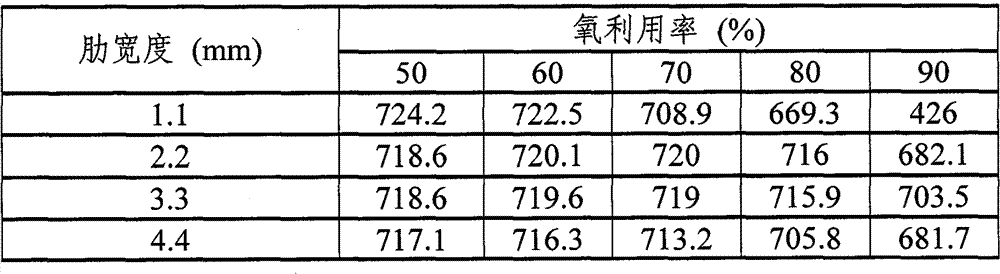
Table 1 expression under these conditions, the relation between the interval between stream and the stream (below be called " rib width ") and coefficient of oxygen utilization and the voltage (mV).
Table 1
Relation between table 2 expression rib width and contact resistance and the resistance loss (voltage reduction amount).Can know that from table 2 along with rib width becomes big, contact resistance and resistance loss have also increased.It the reasons are as follows said.After rib width became greatly, the contact area of separator and GDL increased.The contact area of separator and GDL is applying the unit under the situation of identical fastening force after increasing, and the load of unit are descends.And because the load of unit are descends, contact resistance is exponential increase.Therefore, because rib width increases, contact resistance increases, and it is big that impedance loss becomes.
Table 2
| Rib width (mm) |
1.1 |
2.2 |
3.3 |
4.4 |
5.5 |
| Contact resistance (m Ω) |
0.00169 |
0.004917 |
0.00922 |
0.014138 |
0.019977 |
| Resistance loss (mV) |
0.415615 |
2.418122 |
6.800967 |
13.9042 |
24.55905 |
Table 3 is the results that from the result of table 1, deduct gained behind the resistance loss of table 2.Because table 3 considers the resistance loss of hypothesis, so compare with table 1, expression is more near the numerical value of actual value.
Table 3
Figure 14 is illustrated in rib width and the figure of the relation between the voltage under the coefficient of oxygen utilization 80% in the table 3.
In the figure of Figure 14, vertical pivot is represented voltage, and transverse axis is represented rib width.The zone of rib width till 1.1mm to 3.3mm, along with the increase of rib width, voltage also increases.When voltage is 3.3mm in rib width, has peak value.Voltage when voltage the when voltage when rib width is 4.4mm is 3.3mm less than rib width and rib width are 2.2mm.
According to above result, can know that under above-mentioned analysis condition in order to keep higher voltage, optimal rib width is 2.2mm~3.3mm.
(experimental example 2)
In this experimental example, use the program identical, the experiment of having derived the only interval between stream and the stream is described with experimental example 1.In this experimental example, different with experimental example 1, the parameter of GDL thickness is made as 200 μ m.Analysis condition beyond the GDL film is identical with experimental example 1.
Table 4 is represented under these conditions, the relation between rib width and coefficient of oxygen utilization and the voltage (mV).
Table 4
Table 5 is the results that from the result of table 4, deduct gained behind the resistance loss of table 2.Because table 5 considers the resistance loss of estimation, so compare with table 4, expression is more near the numerical value of actual value.
Table 5
Figure 15 is illustrated in rib width and the figure of the relation between the voltage under the coefficient of oxygen utilization 80% in the table 5.
In the figure of Figure 15, vertical pivot is represented voltage, and transverse axis is represented rib width.The zone of rib width till 1.1mm to 2.2mm, along with the increase of rib width, voltage also increases.When voltage is 2.2mm in rib width, has peak value.The zone of rib width till 2.2mm to 4.4mm, along with the increase of rib width, voltage reduces.Voltage when voltage the when voltage when rib width is 4.4mm is significantly less than rib width and is 2.2mm and rib width are 3.3mm.
According to above result, can know that under above-mentioned analysis condition in order to keep higher voltage, optimal rib width is 2.2mm~3.3mm.
Result according to experimental example 1 and experimental example 2; Can know; At GDL thickness is that 200 μ m~300 μ m, flow path width are that 1.1mm, flow path depth are under the situation of 1.1mm; When rib width was 2.2mm~3.3mm, when promptly rib width was 2 times to 3 times of flow path width, cell of fuel cell can carry out the generating of full blast.
The application advocates that (Japan) spy who submits to based on June 21st, 2006 is willing to the priority of 2006-171995.The content of putting down in writing is all quoted by the application in this application specification.
Utilizability in the industry
Cell of fuel cell of the present invention and cell of fuel cell storehouse, it is useful not having in the polymer electrolyte fuel cell etc. of humidification operation at the low humidification of high temperature or high temperature.