CN101725755B - Automatic water outlet control device and automatic water outlet device - Google Patents
Automatic water outlet control device and automatic water outlet device Download PDFInfo
- Publication number
- CN101725755B CN101725755B CN2009102012036A CN200910201203A CN101725755B CN 101725755 B CN101725755 B CN 101725755B CN 2009102012036 A CN2009102012036 A CN 2009102012036A CN 200910201203 A CN200910201203 A CN 200910201203A CN 101725755 B CN101725755 B CN 101725755B
- Authority
- CN
- China
- Prior art keywords
- water outlet
- automatic water
- host cavity
- circuit board
- assembly
- Prior art date
- Legal status (The legal status is an assumption and is not a legal conclusion. Google has not performed a legal analysis and makes no representation as to the accuracy of the status listed.)
- Expired - Fee Related
Links
Images


Classifications
-
- E—FIXED CONSTRUCTIONS
- E03—WATER SUPPLY; SEWERAGE
- E03C—DOMESTIC PLUMBING INSTALLATIONS FOR FRESH WATER OR WASTE WATER; SINKS
- E03C1/00—Domestic plumbing installations for fresh water or waste water; Sinks
- E03C1/02—Plumbing installations for fresh water
- E03C1/05—Arrangements of devices on wash-basins, baths, sinks, or the like for remote control of taps
- E03C1/055—Electrical control devices, e.g. with push buttons, control panels or the like
- E03C1/057—Electrical control devices, e.g. with push buttons, control panels or the like touchless, i.e. using sensors
-
- E—FIXED CONSTRUCTIONS
- E03—WATER SUPPLY; SEWERAGE
- E03C—DOMESTIC PLUMBING INSTALLATIONS FOR FRESH WATER OR WASTE WATER; SINKS
- E03C1/00—Domestic plumbing installations for fresh water or waste water; Sinks
- E03C1/02—Plumbing installations for fresh water
- E03C1/08—Jet regulators or jet guides, e.g. anti-splash devices
-
- Y—GENERAL TAGGING OF NEW TECHNOLOGICAL DEVELOPMENTS; GENERAL TAGGING OF CROSS-SECTIONAL TECHNOLOGIES SPANNING OVER SEVERAL SECTIONS OF THE IPC; TECHNICAL SUBJECTS COVERED BY FORMER USPC CROSS-REFERENCE ART COLLECTIONS [XRACs] AND DIGESTS
- Y10—TECHNICAL SUBJECTS COVERED BY FORMER USPC
- Y10T—TECHNICAL SUBJECTS COVERED BY FORMER US CLASSIFICATION
- Y10T137/00—Fluid handling
- Y10T137/8593—Systems
- Y10T137/85946—Faucet connected, sink drained
Landscapes
- Health & Medical Sciences (AREA)
- Life Sciences & Earth Sciences (AREA)
- Engineering & Computer Science (AREA)
- Hydrology & Water Resources (AREA)
- Public Health (AREA)
- Water Supply & Treatment (AREA)
- Magnetically Actuated Valves (AREA)
- Domestic Plumbing Installations (AREA)
- Fluid-Driven Valves (AREA)
Abstract
本发明公开了一种自动出水控制装置,安装在厨卫领域内自动出水装置的出水位置,包括外壳、收容于外壳内的感应器组件、出水组件以及电磁阀组件。其中外壳包括收容感应器组件的第一收容腔、收容电磁阀组件的第二收容腔、收容出水组件的第三收容腔以及进水腔。感应器组件包括电路板以及设置在电路板上的感应器。电路板上设有处理器。电磁阀组件包括与电路板电性连接的电磁阀以及与电磁阀配合的膜片。其中膜片运动使得进水腔与第三收容腔连通或被阻断而实现出水组件的出水或止水。本发明自动出水控制装置结构紧凑、利于产品小型化。
The invention discloses an automatic water outlet control device, which is installed at the water outlet position of the automatic water outlet device in the field of kitchen and bathroom, and comprises a casing, an inductor assembly accommodated in the casing, a water outlet assembly, and a solenoid valve assembly. Wherein the shell includes a first accommodation chamber for storing the sensor assembly, a second accommodation chamber for storing the solenoid valve assembly, a third accommodation chamber for storing the water outlet assembly, and a water inlet chamber. The sensor assembly includes a circuit board and a sensor arranged on the circuit board. A processor is provided on the circuit board. The solenoid valve assembly includes a solenoid valve electrically connected to the circuit board and a diaphragm matched with the solenoid valve. Wherein the movement of the diaphragm makes the water inlet chamber communicate with the third receiving chamber or is blocked to realize the water outlet or water stop of the water outlet assembly. The automatic water outlet control device of the invention has a compact structure and is beneficial to product miniaturization.
Description
技术领域 technical field
本发明涉及一种应用于厨卫领域内的自动出水控制装置及安装该自动出水控制装置的自动出水装置,如自动感应水龙头等。The invention relates to an automatic water discharge control device applied in the field of kitchen and bathroom and an automatic water discharge device installed with the automatic water discharge control device, such as an automatic induction faucet and the like.
背景技术 Background technique
自动感应技术被广泛应用于厨卫领域内的出水装置,例如水龙头、小便器等。以下以自动感应水龙头为例。现有技术中,自动感应水龙头主要包括:水龙头本体、检测感应区域是否有目标物(如人手)进入或离开的接近感应器以及连接水龙头本体的电磁阀及控制组件。所述接近感应器有传统的红外感应器、红外距离检测感应器(PSD)、微波检测感应器、超声波检测感应器等。一般来讲,感应器安装在水龙头水嘴上或水龙头本体上。而电磁阀与控制组件安装在安装水龙头台盆的下面。Automatic sensing technology is widely used in water outlet devices in the kitchen and bathroom field, such as faucets, urinals, etc. The following is an example of an automatic sensor faucet. In the prior art, an automatic sensing faucet mainly includes: a faucet body, a proximity sensor for detecting whether a target (such as a human hand) enters or leaves the sensing area, and a solenoid valve and a control component connected to the faucet body. The proximity sensor includes a traditional infrared sensor, an infrared distance detection sensor (PSD), a microwave detection sensor, an ultrasonic detection sensor, and the like. Generally speaking, the sensor is installed on the faucet nozzle or on the faucet body. The solenoid valve and the control assembly are installed under the basin where the faucet is installed.
惟,现有技术中的自动感应水龙头,由于零组件比较多,电磁阀与控制组件等部件又需要在台盆下完成安装,因此,给安装以及后续的维护带来了很大的不便,而且也不利于产品小型化。However, the automatic sensor faucet in the prior art has many components, and the solenoid valve and control components need to be installed under the basin, so it brings great inconvenience to the installation and subsequent maintenance. It is also not conducive to product miniaturization.
发明内容 Contents of the invention
本发明的目的在于提供一种新型的自动出水控制装置及安装该自动出水控制装置的自动出水装置。The object of the present invention is to provide a novel automatic water discharge control device and an automatic water discharge device equipped with the automatic water discharge control device.
本发明的目的通过如下技术方案之一实现:一种自动出水控制装置,安装在厨卫领域内自动出水装置的出水位置,包括外壳、收容于外壳内的感应器组件、出水组件以及电磁阀组件。其中外壳包括收容感应器组件的第一收容腔、收容电磁阀组件的第二收容腔、收容出水组件的第三收容腔以及进水腔。感应器组件包括电路板以及设置在电路板上的感应器。电路板上设有处理器。电磁阀组件包括与电路板电性连接的电磁阀以及与电磁阀配合的膜片。其中膜片运动使得进水腔与第三收容腔连通或被阻断而实现出水组件的出水或止水。The purpose of the present invention is achieved by one of the following technical solutions: an automatic water outlet control device installed at the water outlet position of the automatic water outlet device in the kitchen and bathroom field, including a housing, an inductor assembly housed in the housing, a water outlet assembly, and a solenoid valve assembly . The housing includes a first storage cavity for storing the sensor assembly, a second storage cavity for the electromagnetic valve assembly, a third storage cavity for the water outlet assembly, and a water inlet cavity. The sensor assembly includes a circuit board and a sensor arranged on the circuit board. A processor is provided on the circuit board. The solenoid valve assembly includes a solenoid valve electrically connected to the circuit board and a diaphragm matched with the solenoid valve. Wherein the movement of the diaphragm makes the water inlet chamber communicate with the third receiving chamber or is blocked to realize the water outlet or water stop of the water outlet assembly.
所述电磁阀包括阀盖以及设置于阀盖内的电磁铁。其中电磁铁包括缸体、收容于缸体内的阀芯以及设置于阀芯两侧的线圈。其中阀盖与膜片之间形成有膜腔。The solenoid valve includes a valve cover and an electromagnet arranged in the valve cover. Wherein the electromagnet includes a cylinder body, a valve core housed in the cylinder body and coils arranged on both sides of the valve core. A film chamber is formed between the valve cover and the diaphragm.
所述阀盖上设有与膜腔连通的进水通孔以及第三收容腔连通的出水通孔。其中阀芯的移动使得进水通孔与出水通孔连通或被阻断。The valve cover is provided with a water inlet hole in communication with the membrane chamber and a water outlet hole in communication with the third storage chamber. Wherein the movement of the spool makes the water inlet through hole communicate with the water outlet through hole or be blocked.
所述电磁铁横向设置于阀盖内。所述进水通道与出水通道位于阀盖靠近阀芯的一侧。The electromagnet is arranged laterally in the valve cover. The water inlet channel and the water outlet channel are located on the side of the valve cover close to the valve core.
所述外壳上还设有一连通第二收容腔与第三收容腔的通孔。所述出水通道通过该通孔与第三收容腔连通。The shell is also provided with a through hole communicating with the second storage cavity and the third storage cavity. The water outlet channel communicates with the third receiving chamber through the through hole.
所述膜片包括动膜以及安装在动膜上的动片。所述动片上还设有与膜腔连通的补水孔。The membrane includes a moving membrane and a moving piece installed on the moving membrane. The moving piece is also provided with a water supply hole communicating with the membrane cavity.
所述膜片上还设有与补水孔配合的插针。The diaphragm is also provided with pins matched with the water replenishment holes.
所述电路板包括第一部分与第二部分。其中感应器安装于第一部分上,处理器安装于第二部分上。感应器组件安装到外壳上后,电路板的第一部分位于所述外壳的前端端面处且安装感应器的一面朝向需要的感应区域,而第二部分位于第一收容腔内。The circuit board includes a first part and a second part. Wherein the sensor is installed on the first part, and the processor is installed on the second part. After the sensor assembly is installed on the shell, the first part of the circuit board is located at the front end of the shell and the side on which the sensor is installed faces the required sensing area, while the second part is located in the first receiving cavity.
所述电路板为柔性电路板。The circuit board is a flexible circuit board.
所述第一收容腔与第三收容腔的开口在外壳的前端,而所述第二收容腔与进水腔的开口在外壳的后端,且所述进水腔位于第二收容腔的一侧。The openings of the first storage chamber and the third storage chamber are at the front end of the casing, and the openings of the second storage chamber and the water inlet chamber are at the rear end of the casing, and the water inlet chamber is located at one side of the second storage chamber. side.
本发明的目的通过如下技术方案之二实现:一种自动出水装置,包括安装于该自动出水装置的出水位置处的自动出水控制装置。该自动出水控制装置与自动出水装置的进水管连通,包括:外壳、收容于外壳内的感应器组件、出水组件以及电磁阀组件。其中外壳包括收容感应器组件的第一收容腔、收容电磁阀组件的第二收容腔、收容出水组件的第三收容腔以及与所述进水管连通的进水腔。感应器组件包括电路板以及设置在电路板上用于检测是否有目标物进入或离开自动出水装置感应区域的感应器。所述电路板上设有处理器。电磁阀组件包括与电路板电性连接的电磁阀以及与电磁阀配合的膜片。其中膜片运动使得进水腔与第三收容腔连通或被阻断而实现出水组件的出水或止水。The object of the present invention is achieved through the second technical solution as follows: an automatic water discharge device, including an automatic water discharge control device installed at the water discharge position of the automatic water discharge device. The automatic water outlet control device communicates with the water inlet pipe of the automatic water outlet device, and includes: a casing, an inductor assembly accommodated in the casing, a water outlet assembly and a solenoid valve assembly. Wherein the shell includes a first accommodation chamber for storing the sensor assembly, a second accommodation chamber for storing the solenoid valve assembly, a third accommodation chamber for storing the water outlet assembly, and a water inlet chamber communicated with the water inlet pipe. The sensor assembly includes a circuit board and a sensor arranged on the circuit board for detecting whether a target enters or leaves the sensing area of the automatic water outlet device. A processor is arranged on the circuit board. The solenoid valve assembly includes a solenoid valve electrically connected to the circuit board and a diaphragm matched with the solenoid valve. Wherein the movement of the diaphragm makes the water inlet chamber communicate with the third receiving chamber or is blocked to realize the water outlet or water stop of the water outlet assembly.
所述电磁阀包括阀盖以及设置于阀盖内的电磁铁,其中电磁铁包括缸体、收容于缸体内的阀芯以及设置于阀芯两侧的线圈。其中阀盖与膜片之间形成有膜腔。The solenoid valve includes a valve cover and an electromagnet arranged in the valve cover, wherein the electromagnet includes a cylinder body, a valve core accommodated in the cylinder body and coils arranged on both sides of the valve core. A film chamber is formed between the valve cover and the diaphragm.
所述阀盖上设有与膜腔连通的进水通孔以及第三收容腔连通的出水通孔。其中阀芯的移动使得进水通孔与出水通孔连通或被阻断。The valve cover is provided with a water inlet hole in communication with the membrane chamber and a water outlet hole in communication with the third storage chamber. Wherein the movement of the spool makes the water inlet through hole communicate with the water outlet through hole or be blocked.
所述外壳上还设有一连通第二收容腔与第三收容腔的通孔。所述出水通道通过该通孔与第三收容腔连通。The shell is also provided with a through hole communicating with the second storage cavity and the third storage cavity. The water outlet channel communicates with the third receiving chamber through the through hole.
所述电磁铁横向设置于阀盖内。所述进水通道与出水通道位于阀盖靠近阀芯的一侧。The electromagnet is arranged laterally in the valve cover. The water inlet channel and the water outlet channel are located on the side of the valve cover close to the valve core.
所述膜片包括动膜以及安装在动膜上的动片。所述动片上还设有与膜腔连通的补水孔。The membrane includes a moving membrane and a moving piece installed on the moving membrane. The moving piece is also provided with a water supply hole communicating with the membrane cavity.
所述膜片上还设有与补水孔配合的插针。The diaphragm is also provided with pins matched with the water replenishment holes.
所述电路板包括第一部分与第二部分,其中感应器安装于第一部分上,处理器安装于第二部分上。感应器组件安装到外壳上后,电路板的第一部分位于所述外壳的前端端面处且安装感应器的一面朝向需要的感应区域,而第二部分位于第一收容腔内。The circuit board includes a first part and a second part, wherein the sensor is installed on the first part, and the processor is installed on the second part. After the sensor assembly is installed on the shell, the first part of the circuit board is located at the front end of the shell and the side on which the sensor is installed faces the required sensing area, while the second part is located in the first receiving cavity.
所述电路板为柔性电路板。The circuit board is a flexible circuit board.
所述第一收容腔与第三收容腔的开口在外壳的前端,而所述第二收容腔与进水腔的开口在外壳的后端,且所述进水腔位于第二收容腔的一侧。The openings of the first storage chamber and the third storage chamber are at the front end of the casing, and the openings of the second storage chamber and the water inlet chamber are at the rear end of the casing, and the water inlet chamber is located at one side of the second storage chamber. side.
所述自动出水装置为自动感应水龙头。The automatic water outlet device is an automatic induction faucet.
与现有技术相比较,本发明自动出水控制装置结构紧凑、利于产品小型化。而安装该自动出水控制装置的自动出水装置,结构更加紧凑、安装及维修方便。Compared with the prior art, the automatic water outlet control device of the present invention has a compact structure and is beneficial to product miniaturization. The automatic water discharge device installed with the automatic water discharge control device has a more compact structure and is convenient for installation and maintenance.
附图说明 Description of drawings
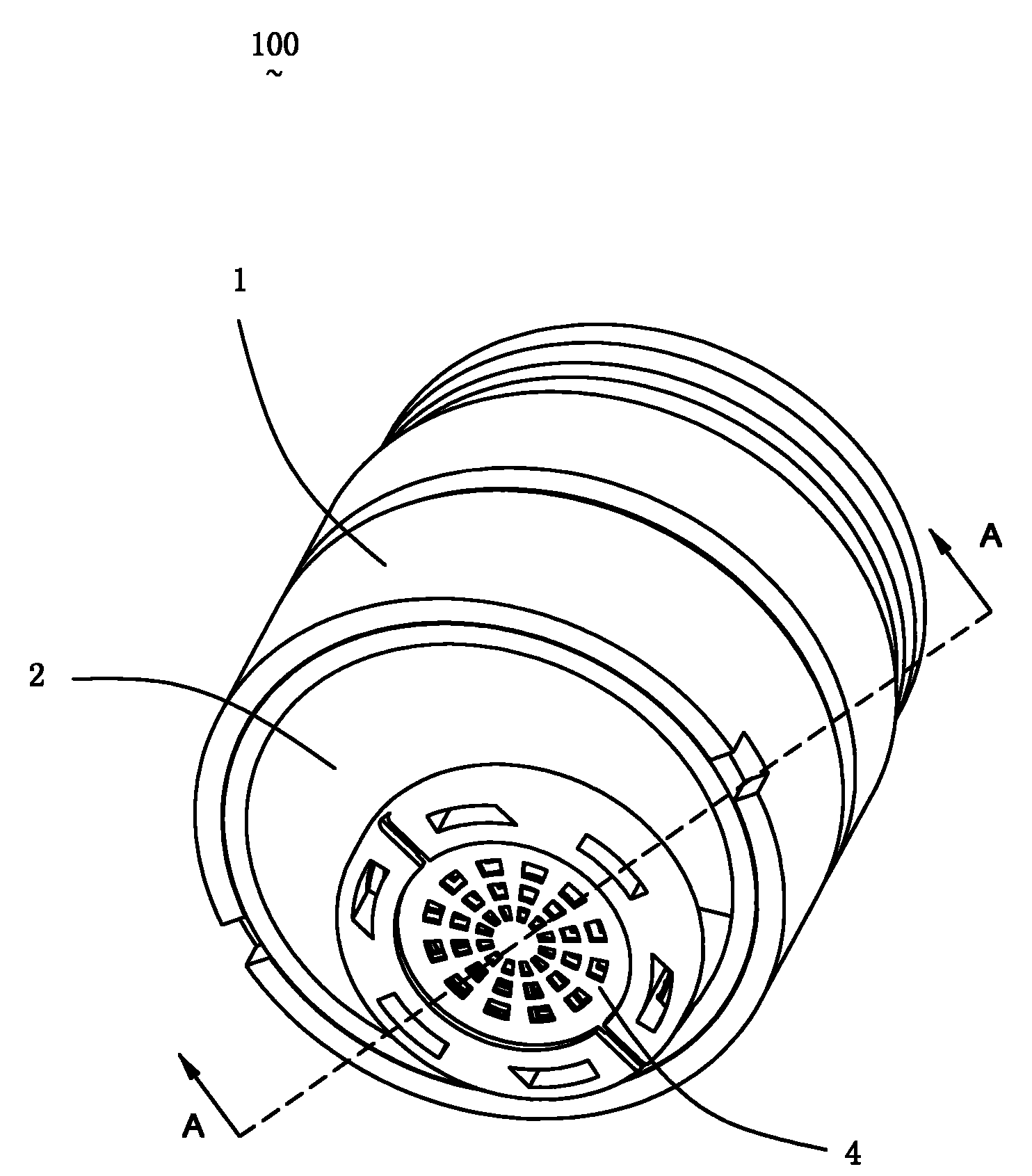
图1是本发明自动出水控制装置的立体示意图。Fig. 1 is a three-dimensional schematic diagram of the automatic water outlet control device of the present invention.
图2是图1的分解示意图。FIG. 2 is an exploded schematic diagram of FIG. 1 .
图3是图2另一角度视图。Fig. 3 is another perspective view of Fig. 2 .
图4是沿图1中A-A线的剖面示意图。Fig. 4 is a schematic cross-sectional view along line A-A in Fig. 1 .
图5是沿图4中B-B线的剖面示意图。Fig. 5 is a schematic cross-sectional view along line B-B in Fig. 4 .
图6是沿图4中C-C线的剖面示意图。Fig. 6 is a schematic cross-sectional view along line C-C in Fig. 4 .
图7是沿图6中D-D线的剖面示意图。Fig. 7 is a schematic cross-sectional view along line D-D in Fig. 6 .
图8是沿图5中E-E线的部分剖面示意图。FIG. 8 is a schematic partial cross-sectional view along line E-E in FIG. 5 .
图9是安装自动出水控制装置的自动感应水龙头的示意图。Fig. 9 is a schematic diagram of an automatic sensor faucet equipped with an automatic water outlet control device.
具体实施方式 Detailed ways
下面参照附图具体介绍本发明的各种实施例,图中相同的结构或功能用相同的数字标出。应该指出的是,附图的目的只是便于对本发明具体实施例的说明,不是一种多余的叙述或是对本发明范围的限制,此外,附图没有必要按比例画出。Various embodiments of the present invention will be described in detail below with reference to the accompanying drawings, in which the same structures or functions are marked with the same numerals. It should be pointed out that the purpose of the drawings is only to facilitate the description of the specific embodiments of the present invention, and is not a redundant description or limitation to the scope of the present invention. In addition, the drawings are not necessarily drawn to scale.
如图1至图3所示,本发明涉及一种克服现有技术中的不足,集成度高、利于产品小型化的自动出水控制装置100及安装该自动出水控制装置100的自动出水装置(如自动感应水龙头等,如图9所示)。As shown in Figures 1 to 3, the present invention relates to an automatic water
本发明自动出水控制装置100,包括外壳1、安装于外壳1内的感应器组件2、与感应器组件2电性连接的电磁阀组件3以及出水组件4。另外,本发明自动出水控制装置100还包括一主要起密封作用的端盖5。The automatic water
所述外壳1大致为圆柱体结构,具有多个收容腔体,包括:收容感应器组件2的第一收容腔11、收容电磁阀组件3的第二收容腔12、收容出水组件4的第三收容腔13以及与自动出水装置的进水管连通的进水腔14。所述进水腔14位于第二收容腔12的一侧,结构更加紧凑。另,外壳1上还设有一连通第二收容腔12与第三收容腔13的通孔15。The
所述外壳1包括前、后两端,其中所述前端面对使用者,而后端安装于自动出水装置的内部与进水管连通。所述收容感应器组件2的第一收容腔11以及收容出水组件4的第三收容腔13的开口在外壳1的前端,而收容电磁阀组件3的第二收容腔12与进水腔14的开口在外壳1的后端。安装后,所述感应器组件2与出水组件4大致位于外壳1的前端端面位置处。The
所述感应器组件2包括与电磁阀31电性连接的电路板21以及设置在电路板21上的感应器(未图示)。其中所述电路板21上还设有处理器以及其他电子元器件。所述感应器一般为红外感应器,包括红外发射器及红外接收器。诚然,所述感应器也可以是微波感应器、超声波感应器等其他类型用以检测目标物是否进入或离开感应区域的接近感应器。而所述电路板21包括第一部分211与第二部分212。所述第一部分211上安装感应器,而第二部分212上安装处理器等电子元器件。所述安装感应器的第一部分211外表面还设置一透光板22。安装时,所述第二部分212安装于第一收容腔11内,而安装透光板22的第一部分211则位于所述外壳1的前端端面处。The
在本发明一优选的实施方式中,所述电路板21为柔性电路板,使得第二部分212可以折叠或卷曲而很方便地收容进第一收容腔11内。一般情况下,出水组件4与外壳1一样,为圆柱体形。为了与该出水组件4配合安装在外壳1的前端端面位置处,所述电路板21第一部分211与透光板22大致为月牙形。In a preferred embodiment of the present invention, the
所述电磁阀组件3包括电磁阀31、与电磁阀31与配合的膜片32。打开和关闭电磁阀31而驱动膜片32运动。所述膜片32设置在电磁阀31的下方。The
图4是沿图1中A-A线的剖面示意图。图5、图6分别为沿图4中B-B线和C-C线的剖面示意图。其中所述A-A线是剖在动膜322的中心与出水通道317的中心所在的直线上。所述B-B线剖在膜腔33位置处。所述C-C线剖在电磁铁312阀芯314的中心。Fig. 4 is a schematic cross-sectional view along line A-A in Fig. 1 . Fig. 5 and Fig. 6 are schematic cross-sectional views along line B-B and line C-C in Fig. 4 respectively. Wherein the A-A line is cut on the straight line where the center of the moving
结合图4所示,所述电磁阀31包括阀盖311以及收容于阀盖311内的电磁铁312。所述膜片32位于阀盖311的下方,并且在膜片32与阀盖311之间形成膜腔33。所述电磁铁312包括缸体313、收容于缸体313内可来回移动的阀芯314以及设置于阀芯314两侧的线圈315。给电磁阀31通电或断电,阀芯314在电磁力的作用下可来回伸缩移动。另外,所述电磁阀31上还设有与电路板21电性连接的线缆310。As shown in FIG. 4 , the
图7是沿图6中D-D线的剖面示意图。所述D-D线剖在进水通道316上。Fig. 7 is a schematic cross-sectional view along line D-D in Fig. 6 . The D-D line is cut on the
进一步结合图5至图7所示,所述阀盖311上设有与膜腔33连通的进水通道316以及与第三收容腔13连通的出水通道317。当出水组件4安装到第三收容腔13后,所述出水通道317与第三收容腔13连通也就是出水通道317与出水组件4导通。当电磁阀31关闭时,所述阀芯314伸出而阻挡在进水通道316与出水通道317之间,即所述进水通道316与出水通道317被阻断。当电磁阀31打开时,所述阀芯314向缸体313内部回缩。所述进水通道316与出水通道317连通。在本发明另一优选的实施方式中,所述阀芯314的自由端上设有密封件。这样设置,可使得当阀芯314阻隔在进水通道316与出水通道317之间时,具有良好的密封效果。Further referring to FIG. 5 to FIG. 7 , the
所述膜片32还包括动膜321以及安装在动膜321上的动片322。所述动片322上还设有与膜腔33连通的补水孔323。所述动膜321一般为较软的橡胶材料,而动片322一般为较硬的塑料材料。在本发明一优选的实施方式中,所述膜片32上还有与补水孔323配合的插针324,以防止异物堵塞补水孔323(可参考图8)。膜片32在工作时,所述动片322带动动膜321运动。The
在本发明一优选的实施方式中,所述电磁铁312横向设置于阀盖311内,所述进水通道316与出水通道317位于阀盖311靠近阀芯314的一侧。诚然,在本发明其他的实施方式中,所述电磁铁312可以以其他合适的角度安装。所述进水通道316与出水通道317根据电磁铁312的安装位置进行适当调整。In a preferred embodiment of the present invention, the
所述端盖5设有与进水腔14连通的进水口51。所述端盖5将外壳1后端除进水腔14外的其他地方密封。所述连接电路板21的电源线(未图示)通过端盖5的出线口52连接出去,并与自动出水装置的外接电源连接。所述外接电源可以是直流电源,也可以是交流电源。The
在本发明另一实施方式中,所述端盖5也不是必须的,可以用密封材料代替,只需将外壳1除进水腔14以外需要密封的地方进行有效密封即可。In another embodiment of the present invention, the
另外,出水组件4作为出水装置的出水部件,可以为安装在自动感应水龙头上的起泡器,或者是安装在自动感应小便器上的喷水器等。In addition, the
安装时,感应器组件2从外壳1的前端装入第一收容腔11内。安装感应器的电路板21第一部分211位于外壳1前端的端面处,使得感应器可以处于理想的感应位置。所述外壳1将电路板21密封在第一收容腔11内,以防止有水流入电路板21。During installation, the
所述出水组件4从外壳1的前端装入第三收容腔13内,且该出水组件4的外端位于外壳前端的端面位置处。在本发明一优选的实施方式中,该出水组件4上和第三收容腔13内设有螺纹,通过螺纹连接安装到外壳1上。当然,出水组件4与外壳1的连接方式不限于此,也可以通过螺钉安装或焊接固定等连接方式。The
图8是沿图5中E-E线的部分剖面示意图。所述E-E线剖在所述膜片32与补水孔323的中心所在的直线上。进一步结合图8所示,所述电磁阀组件3从外壳1的后端面装入第二收容腔12内。装入电磁阀组件3之后,所述膜片32位于进水腔14与第三收容腔13之间。所述膜片32运动可使得进水腔14与第三收容腔13连通或被阻断。当出水组件4安装到第三收容腔13后,进水腔14与第三收容腔13连通或被阻断,也就是进水腔14与出水组件4连通或被阻断。当所述膜片32受到膜腔33内的水压力而阻隔在进水腔14与第三收容腔13之间时,所述进水腔14与第三收容腔13被阻断。所述水流被密封在进水腔14内。如目前图8所示的状态,即为膜片32阻隔在进水腔与第三收容腔13之间。而当所述膜腔33内的水被释放,膜片32朝着膜腔33的方向运动。所述进水腔14与第三收容腔13连通。这样,进水腔14内的水流就可流入第三收容腔13内并从出水组件4排出。FIG. 8 is a schematic partial cross-sectional view along line E-E in FIG. 5 . The E-E line is cut on the straight line where the center of the
所述电磁阀组件3安装到外壳1上后,所述通孔15与出水通道317对接。因此,到达出水通道317的水流经过通孔15进入到第三收容腔13内而可从出水组件4排出。在本发明一优选的实施方式中,出于密封的考虑,膜片32一部分位于出水通道317与通孔15之间,因而所述膜片32上还设有一小孔325,使得该小孔325与出水通道317及通孔15对接而形成水流通道。诚然,也可以直接使得出水通道317与通孔15对接,通过另外设置的密封件进行密封。After the
所述端盖5安装在外壳1后端的端面上密封电磁阀组件3与感应器组件2而端盖5上的进水口51与外壳1进水腔14对接。The
这样,本发明自动出水控制装置100便组装在一起。In this way, the automatic water
使用时,自动出水控制装置100安装至自动出水装置上,例如自动感应水龙头、自动感应小便器等自动厨卫产品。所述自动出水控制装置100安装在自动出水装置的出水位置处。When in use, the automatic water
以下的描述将以自动出水控制装置100安装在自动感应水龙头上为例。如图9所示,本发明自动感应水龙头200包括本体201以及水嘴202。所述自动出水控制装置100安装于自动感应水龙头200的水嘴202位置处。所述感应器组件2面向自动感应水龙头200的感应区域。而所述出水组件4朝向自动感应水龙头200的使用区域。电源线9通过水龙头本体201连接到水龙头外接电源(未图示)上。所述外接电源采用直流电时,外接电源安装在安装该自动感应水龙头的台盆下方或水龙头本体201内。进一步地,在功耗、体积等条件允许的情况下,所述外接电源采用直流电,如锂电子。可以直接将锂电子安装在自动出水控制装置100外壳1的后端或直接安装进外壳1内,而与自动出水控制装置100一起安装进水龙头200水嘴202内。从而无需通过电源线9水龙头本体201连接出去,减少零部件,利于安装与维护。The following description will take the automatic water
所述自动出水控制装置100通过螺纹或螺钉等安装形式安装在水龙头水嘴202上。水流从自动感应水龙头200的进水管流入外壳1的进水腔14后,流经膜片32的补水孔323进入到膜片32与电磁阀31之间的膜腔33内。进一步地,水流进入电磁阀31的进水通道316到达电磁铁312阀芯314位置初始位置时,电磁阀31关闭,电磁铁312阀芯314阻隔在进水通道316与出水通道317之间。水流被电磁铁312阀芯314阻挡而无法从进水通道316流到出水通道317。此时,由于膜腔33内的水量一定,在水的压力作用下,膜片32一直阻隔在进水腔14与第三收容腔13之间,使得水流被密封在进水腔14与电磁阀组件3内,而无法从出水组件4流出。The automatic water
当所述感应器检测到有目标物进入感应区域,即检测到有人手进入水龙头感应区域,电路板21上的处理器处理该检测信号,进一步地控制电磁阀31开启。所述电磁阀31开启后,电磁铁312阀芯314在电磁力的作用下回缩而无法阻隔进水通道316与出水通道317。此时水流从进水通道316到达出水通道317并经小孔325、通孔15,进入第三收容腔13并从出水组件4流出。因此,膜腔33内的水量减少。从而导致膜片32面向膜腔33的一侧所承受的压力减小。在压力的作用下,膜片32朝着膜腔33的方向运动而使得膜片32无法阻隔进水腔14与第三收容腔13。所述进水腔14与第三收容腔13导通,水流可直接从进水腔14流进第三收容腔13而从出水组件4流出,从而实现自动感应水龙头200的自动出水。When the sensor detects that a target object enters the sensing area, that is, it detects that someone's hand has entered the sensing area of the faucet, the processor on the
当所述感应器检测到目标物离开感应区域,即没有使用者使用自动感应水龙头200。所述处理器处理该检测信号,控制电磁阀31关闭。所述电磁阀31关闭,阀芯314回复到初始位置,阻隔进水通道316与出水通道317。此时,水流不断从膜片32补水孔323进入膜腔33内,而又无法从出水通道317流出。从而使得膜片32与电磁阀31之间膜腔33内的水重新增多,膜片32面向膜腔33的一侧所承受的压力增大而大于膜片32背向膜腔33的一侧所承受的水的压力。因而,膜片32朝着背向膜腔33的方向运动。这样膜片32重新阻隔在进水腔14与第三收容腔13之间,水流被密封在进水腔14与电磁阀组件3内。从而使得进水腔14内的水无法流进第三收容腔13,从而实现自动感应水龙头200的自动止水。When the sensor detects that the target leaves the sensing area, that is, no user uses the
所述电磁阀31阀芯314的移动使得进水通道316与出水通道317连通或被阻断。所述膜片32的运动可使得进水腔14与第三收容腔13连通或被阻断。因此,开启和关闭所述电磁阀31,驱动膜片32运动,使得第三收容腔13与进水腔14连通或被阻断,而实现出水组件4的出水与止水,并最终实现自动感应水龙头200的自动出水或自动止水。The movement of the
本发明自动出水控制装置100将感应器组件2、电磁阀组件3以及出水组件4集成在外壳1内,从而使得结构更加紧凑,利于产品小型化。当安装到自动感应水龙头200等自动出水装置上时,可以直接安装在水龙头水嘴202位置,安装方便,且可简化结构,不用另外增加电磁阀组件3、控制器组件等部件。这样也使得安装所述自动出水控制装置100的自动出水装置,结构更加紧凑、安装及维修方便。The automatic water
同时,本发明自动出水控制装置100中电磁阀组件3体积更小,效率更高。所述电磁铁312横向设置在电磁阀31的阀盖311内,而所述膜片32位于电磁阀31的下方。所述阀盖311上设有进水通道316与出水通道317,两者通过电磁铁312阀芯314的移动而导通或被阻断,进一步使得电磁阀组件3开启或关闭。这样设置,使得电磁铁312阀芯314移动较短的距离,就能实现电磁阀组件3的开启或关闭。现有技术中,一般利用电磁阀阀芯直接作用于膜片上。但是,由于膜片运动的行程较长,导致阀芯移动的行程也变长,这样使得电磁阀效率降低,体积无法减小。因此,相比现有技术,本发明通过如上结构,使得电磁铁312阀芯314的运动行程变短,电磁力的效率提高,从而使得电磁铁312体积更小,最终使得电磁阀组件3的体积变小。当然,在空间允许的情况下,本发明自动出水控制装置100也可以采用现有技术中利用阀芯直接驱动膜片的方式。At the same time, the
进一步地,所述感应器组件2与出水组件4从外壳1的前端装入,而所述电磁阀组件3从外壳1的后端装入。使得本发明自动出水控制装置100安装简单,利于生产。Further, the
虽然上面已经揭示了本发明的具体实施方式,但是它们不是本发明范围的局限,熟知本技术领域的人员对以上所述具体实施的修改和变化也包含在本发明的范围之内。Although specific implementations of the present invention have been disclosed above, they are not limitations of the scope of the present invention. Modifications and changes to the above specific implementations by those skilled in the art are also included in the scope of the present invention.
Claims (2)
Priority Applications (2)
| Application Number | Priority Date | Filing Date | Title |
|---|---|---|---|
| CN2009102012036A CN101725755B (en) | 2009-12-16 | 2009-12-16 | Automatic water outlet control device and automatic water outlet device |
| US12/967,502 US8549677B2 (en) | 2009-12-16 | 2010-12-14 | Automatic water flushing control device and its faucet |
Applications Claiming Priority (1)
| Application Number | Priority Date | Filing Date | Title |
|---|---|---|---|
| CN2009102012036A CN101725755B (en) | 2009-12-16 | 2009-12-16 | Automatic water outlet control device and automatic water outlet device |
Publications (2)
| Publication Number | Publication Date |
|---|---|
| CN101725755A CN101725755A (en) | 2010-06-09 |
| CN101725755B true CN101725755B (en) | 2012-07-04 |
Family
ID=42447107
Family Applications (1)
| Application Number | Title | Priority Date | Filing Date |
|---|---|---|---|
| CN2009102012036A Expired - Fee Related CN101725755B (en) | 2009-12-16 | 2009-12-16 | Automatic water outlet control device and automatic water outlet device |
Country Status (2)
| Country | Link |
|---|---|
| US (1) | US8549677B2 (en) |
| CN (1) | CN101725755B (en) |
Families Citing this family (11)
| Publication number | Priority date | Publication date | Assignee | Title |
|---|---|---|---|---|
| US8805963B2 (en) | 2010-04-01 | 2014-08-12 | Apple Inc. | Real-time or near real-time streaming |
| US9695579B2 (en) | 2011-03-15 | 2017-07-04 | Sloan Valve Company | Automatic faucets |
| WO2012125213A1 (en) * | 2011-03-15 | 2012-09-20 | Sloan Valve Company | Automatic faucets |
| EP2823107A4 (en) | 2012-03-07 | 2016-06-15 | Moen Inc | Electronic plumbing fixture fitting |
| JP6052491B2 (en) * | 2012-08-24 | 2016-12-27 | Toto株式会社 | Automatic faucet |
| CN105805388A (en) * | 2015-01-19 | 2016-07-27 | 莫恩股份有限公司 | Electronic sanitary tool device installed on circuit board |
| DE102016108045A1 (en) | 2016-04-29 | 2017-11-02 | A. u. K. Müller GmbH & Co. KG | Armaturauslass and fitting |
| US10519642B2 (en) | 2017-04-26 | 2019-12-31 | Masco Canada Limited | Adjustable sensor device for a plumbing fixture |
| DE202017103194U1 (en) | 2017-05-26 | 2018-08-28 | Neoperl Gmbh | sanitary valve |
| TWI789701B (en) * | 2018-11-16 | 2023-01-11 | 美商布拉德利夾具公司 | Lavatory fixture, fixture pod assembly for a lavatory fixture and installing method thereof |
| US11761181B2 (en) * | 2021-05-17 | 2023-09-19 | Fuzhou Rajeyn Electronic Science Technology Co., Ltd. | Drawing faucet |
Family Cites Families (11)
| Publication number | Priority date | Publication date | Assignee | Title |
|---|---|---|---|---|
| US3821967A (en) * | 1971-12-30 | 1974-07-02 | O Sturman | Fluid control system |
| US4971106A (en) * | 1987-09-30 | 1990-11-20 | Toto, Ltd. | Automatically operating valve for regulating water flow and faucet provided with said valve |
| US4915347A (en) * | 1989-05-18 | 1990-04-10 | Kohler Co. | Solenoid operated faucet |
| US5125621A (en) * | 1991-04-01 | 1992-06-30 | Recurrent Solutions Limited Partnership | Flush system |
| US5169118A (en) * | 1992-02-11 | 1992-12-08 | Sloan Valve Company | Sensor-operated battery-powered flush valve |
| JP3128790B2 (en) * | 1992-06-15 | 2001-01-29 | 東陶機器株式会社 | Water supply control device |
| TW286345B (en) * | 1993-12-20 | 1996-09-21 | Toto Ltd | |
| JPH0854080A (en) * | 1994-08-09 | 1996-02-27 | Nisshinbo Ind Inc | Pressure control device integral with electronic control device |
| US5911240A (en) * | 1997-10-27 | 1999-06-15 | Kohler Co. | Self-closing solenoid operated faucet |
| US6619320B2 (en) * | 2001-12-04 | 2003-09-16 | Arichell Technologies, Inc. | Electronic metering faucet |
| EP1466118A4 (en) * | 2001-12-26 | 2008-11-12 | Arichell Tech Inc | Bathroom flushers with novel sensors and controllers |
-
2009
- 2009-12-16 CN CN2009102012036A patent/CN101725755B/en not_active Expired - Fee Related
-
2010
- 2010-12-14 US US12/967,502 patent/US8549677B2/en not_active Expired - Fee Related
Also Published As
| Publication number | Publication date |
|---|---|
| US8549677B2 (en) | 2013-10-08 |
| US20120012207A1 (en) | 2012-01-19 |
| CN101725755A (en) | 2010-06-09 |
Similar Documents
| Publication | Publication Date | Title |
|---|---|---|
| CN101725755B (en) | Automatic water outlet control device and automatic water outlet device | |
| CN204953158U (en) | Many gears switch top spraying decoration and spill | |
| US20230313515A1 (en) | Modularized induction flushing device for urinal and induction urinal | |
| CN211472751U (en) | Water inlet device with reversing mechanism and closestool with water inlet device | |
| CN102878339B (en) | Induction water faucet with wireless control component | |
| US11840827B2 (en) | Pull-out spray of pull-out faucet | |
| CN201041234Y (en) | Pressure relief solenoid valve of intelligent toilet seat | |
| CN208651760U (en) | A kind of touch tap | |
| CN110131467A (en) | A bistable solenoid valve and induction water outlet device | |
| CN217153108U (en) | Tap with convenient control function | |
| CN209294471U (en) | The automatically controlled water route switching system of shower faucet | |
| CN101713464B (en) | Automatic effluent control device and automatic effluent device | |
| WO2024037106A1 (en) | Automatic driving unit for toilet flush valve and toilet | |
| CN218818486U (en) | Pull response play water installation of pull tap | |
| CN101839366A (en) | Solenoid valve assembly, automatic water outlet control device and automatic water outlet device | |
| CN218176031U (en) | Intelligent closestool without external power supply | |
| CN115559883A (en) | Diaphragm pump with alternate waterway structure | |
| CN219197603U (en) | A diaphragm pump with two-way water absorption function | |
| CN206617634U (en) | Thrift lock and squirt toy | |
| CN116711970B (en) | Ice bladder water channel structure and control method thereof | |
| CN211459836U (en) | Electric water pressing device and electric water taking system | |
| CN222500495U (en) | A pressure reducing heating module for intelligent bathroom | |
| CN221054367U (en) | Be applied to check valve structure of booster pump | |
| CN218325211U (en) | A Diaphragm Pump with Alternate Waterway Structure | |
| CN215763441U (en) | Shower device with improved water path |
Legal Events
| Date | Code | Title | Description |
|---|---|---|---|
| C06 | Publication | ||
| PB01 | Publication | ||
| C10 | Entry into substantive examination | ||
| SE01 | Entry into force of request for substantive examination | ||
| C14 | Grant of patent or utility model | ||
| GR01 | Patent grant | ||
| CF01 | Termination of patent right due to non-payment of annual fee |
Granted publication date: 20120704 |
|
| CF01 | Termination of patent right due to non-payment of annual fee |