CN101693496A - Multi-rope winding type stage hoisting machine - Google Patents
Multi-rope winding type stage hoisting machine Download PDFInfo
- Publication number
- CN101693496A CN101693496A CN200910066211A CN200910066211A CN101693496A CN 101693496 A CN101693496 A CN 101693496A CN 200910066211 A CN200910066211 A CN 200910066211A CN 200910066211 A CN200910066211 A CN 200910066211A CN 101693496 A CN101693496 A CN 101693496A
- Authority
- CN
- China
- Prior art keywords
- container
- reel
- hoisting
- rope
- main shaft
- Prior art date
- Legal status (The legal status is an assumption and is not a legal conclusion. Google has not performed a legal analysis and makes no representation as to the accuracy of the status listed.)
- Granted
Links
Images


Landscapes
- Storing, Repeated Paying-Out, And Re-Storing Of Elongated Articles (AREA)
- Braking Arrangements (AREA)
Abstract
The invention discloses a multi-rope winding type stage hoisting machine comprising a spindle system, a drive motor, a transmission mechanism, a braking system, a hydraulic station, a manipulation and indication system, a hoisting container and steel wire ropes. The multi-tope winding type stage hoisting machine is characterized in that the hoisting container is divided into a head container and a bottom container, wherein the head container is hung on a winding drum of a spindle and the bottom container is hung below a top container; an underground chamber used for converting and hoisting a load is arranged on a position approaching the middle section of a pitshaft; when the top container hung on one winding drum is hoisted to an unloading position of a well mouth, the bottom container is hoisted to the underground chamber on the middle section of the pitshaft to unload, and the top container hung on the other winding drum is loaded with the load unloaded from the bottom container while the bottom container is loaded with the load from the pitbottom; when the loading process is completed, the containers full of loads start to be hoisted, and the unloaded containers are put down; thus, the loads at the pitbottom are hoisted out of the pitshaft through two-stage hoisting. The invention has the advantages of reducing the sizes of the hoisting container and the pitshaft, reducing the diameter of the hoisting steel wire ropes, enhancing the safety of a hoisting system, satisfying deep pit hoisting requirements, greatly reducing the rope capacity of a hoisting winding drum, reducing the winding layer numbers of the steel wire ropes and avoiding the multilayer transition problem of the steel wire ropes.
Description
Technical field
The present invention relates to a kind of mine hoist art, particularly relate to a kind of multi-rope winding type stage hoisting machine.
Background technology
Mine hoist is one of important and key equipment in mine, is mainly used in colliery, metallic ore and nonmetalliferous ore gig and transfers personnel, promotes coal, ore and transporting material and equipment.It is the important transport facility of getting in touch aboveground and down-hole.Occupying crucial status in mine, is the visual plant in mine.Mine hoist is developed by hand winch, and along with science and technology development, gig develops into the JKA type from the KJ type, and develops into present JK type shaped article by XKT type, XKTB type.
But single-rope hoisting machine and multi-rope hoist commonly used all have some technological deficiencies in actual use.
For example, single rope winding hoist be applied in the subject matter that exists when deep-well promotes have following some:
Wirerope diameter required very greatly when (1) deep-well promoted, and the manufacturing of major diameter steel rope is used all inconvenient.
(2) each lifting container only promotes with steel cable, major accident can occur when disconnected rope appears in steel rope.
(3) the lifting drum width directly influences gig appearance rope amount and promotes the degree of depth, can make the pit shaft width strengthen but increase the reel width thereupon, thereby increases the mine construction cost.
(4) gig connects driving by motor by flexible rod pin coupler, planetary reduction gear and gear coupling, complex structure, and floor area is big.Hydraulic cylinder for adjusting rope or interlocked valve leakage of oil, and pollute brake disc, have a strong impact on the safe reliability of braking.
(5) two reels are installed on the same main shaft of gig, main shaft of hoister extended and overstriking thereupon when the reel width strengthened, the production and processing of main shaft and transportation all effected.
(6) because the reel structure restriction can only be twined steel cable on the reel.
The principle of work of multi-rope winding type gig is: there are two lifting containers in system, each lifting container is with two rope hoistings, fix an end of steel rope and be wrapped on the lifting drum, the other end is walked around head sheave and is hung lifting container, utilize the difference of reel roll mode that steel rope is wrapped with or loosen, promote and transfer work thereby finish.
The mechanics of multi-rope winding type gig is by operating mechanism-axis system; Power system-drive motor; Transmission device-retarder, coupler; Brake system-drg, Hydraulic Station; Observation maneuvering system-depth indicator and depth indicator driving device; Protection system-backplate, guard shield, compositions such as grille.
And the multi-rope winding type gig also can there are the following problems when being applied to deep-well and superdeep well and promoting:
Wirerope diameter required very greatly when (1) deep-well promoted, and needed rope capacity very long, and the manufacturing of the steel rope of major diameter length is used all inconvenient.
(2) the reel width of many rope winding gigs is subjected to the restriction of main shaft device structure, width is limited, must carry out multiple wraps ability meet requirements when rope capacity is very long, but safety of China rules regulation, shaft hoisting system steel rope must not surpass two-layer winding, has seriously limited the hoisting depth of multi-rope winding type gig.
(3) each reel of many rope winding gigs can only promote a lifting container, promoting degree of depth chin-deep, in order to guarantee the mine productivity effect, must reach certain productive capacity, the lifting container oad design-calculated of will having to is very big, and the design production of excessive lifting container and using all has problems.
(4),, can increase the mine construction cost to deep-well so the size of pit shaft also will increase thereupon because the size of lifting container is bigger.
Common single rope winding hoist and multi-rope winding type gig can be run into problems in deep-well and superdeep well lifting, therefore, the user wishes to have a kind of new gig, can reduce volume, finishes the lifting task easily and reliably.
Summary of the invention
Technical matters to be solved by this invention is a kind of multi-rope winding type stage hoisting machine of design, and this gig is low to the volume requirement of pit shaft and main shaft, and actv. satisfies the lifting needs of deep-well and superdeep well.
In order to reach the purpose that solves the problems of the technologies described above, a kind of multi-rope winding type stage hoisting machine of the present invention, comprise axis system, drive motor, transmission device, brake system, handle and indicating system, lifting container and steel rope, be characterised in that: container and end container two parts headed by lifting container divides, first container is suspended on the reel of main shaft by two steel ropes, end container is suspended under the top container by steel rope, a chamber is set in the position in pit shaft stage casing, when top container rises to the well head unloading position, end container be thus lifted to the chamber in pit shaft stage casing and the top container that hangs with another reel parallel, this moment, machine stopped, low container is unloaded to chamber with load, from chamber load is encased in the top container that another reel hangs then, like this by two sections liftings with the load lifting of lifting container to pit shaft.
A kind of multi-rope winding type stage hoisting machine of the present invention, its concrete technical scheme can be: described axis system is by two main shafts, universal coupling, form with move about reel and dead block that two main shafts link to each other respectively, two main shafts are linked together by universal coupling, be synchronized with the movement with realization, the reel that moves about is installed on the main shaft, install and fix reel on another root, each reel adopts dividing plate to be divided into the two parts that equate fully, each part is twined steel cable, two steel ropes hang a top container simultaneously, container at the bottom of each top container hangs down.Technique scheme more specifically technical scheme can be that the non-shaft coupling side of every main shaft all adopts electrical motor directly to connect driving, and device is controlled by operating console, and Hydraulic Station provides braking oil pressure for the multi-rope winding type gig.Technique scheme more specifically technical scheme can also be: all each is fixed by two rolling bearing pedestals two main shafts in the described axis system, disc brake device is all installed at two reel two ends of installing on main shaft, and mandrel surface is all inlayed plastics lining board; The reel that moves about connects firmly on the left and right wheel hub of the reel that moves about by former, assembling two halves brasses in its left and right wheel hub, and the place is connected with rope-adjusting clutch at former, when throw-out-of clutch, the reel that moves about can not rotate with main shaft, and when power-transfer clutch closed, the reel that moves about can rotate with main shaft; Dead block connects firmly on the dead block main shaft by former, and rotates with main shaft.
A kind of multi-rope winding type stage hoisting machine of the present invention, described universal coupling, a kind of large-scale integral formula universal coupling of more specifically saying so connects, this universal coupling connects two main shafts, connect two reels respectively, when a reel promotes, the container of another reel is transferred, the moment of torsion that gravity produced by container of transferring and steel rope is delivered on the main shaft of the reel that is promoting by universal coupling, the moment of torsion that container produced that a part promotes can be balanced, thereby the drive motor power of gig can be significantly reduced; Described axis system adopts the synchronous direct connection of double-motor to drag, the driving efficiency height, and compact conformation has reduced the floor area of machine.Described disc brake device can be the rearmounted build-up type disc-brake of oil cylinder.Hydraulic Station adopts the electrical delay two-stage brake hydraulic station.
A kind of multi-rope winding type stage hoisting machine of the present invention, its concrete mode of operation is: when two containers that connect on dead block are raised, two containers that connect on the reel that move about are lowered, the top container of dead block is thus lifted to the well head unloading position and stops when unloading, end container under the dead block top container rises to the chamber that is used for conversion load in pit shaft stage casing, and load is discharged in chamber, the top container of reel of moving about this moment is also transferred to chamber, container is discharged in the load of chamber at the bottom of the reception dead block, the end container of reel of moving about is transferred to the shaft bottom, loads in the shaft bottom; In dead block top container and end container completion of discharge, after the top container of the reel that moves about and end container loaded and finish, the dead block container began to transfer, and the reel container that moves about begins to promote.And so forth.
The described chamber that is used for conversion load, its concrete structure can be one and have certain volume, the tunnel that can temporarily store lifting load and the lifting load handler is housed.For the mine, generally less length, face size is big and have the tunnel of special purpose to be called chamber, generally all is that machinery and equipment are set, material stored or as other purposes.
Owing to adopted above-mentioned technical scheme, the present invention has following advantage:
(1) lifting container is divided into top lifting container and end lifting container two parts, has reduced the lifting container size, dwindled borehole size;
(2) each top lifting container adopts 2 steel ropes to hang, and has reduced the hoisting cable diameter, has strengthened the safety of elevator system, has satisfied deep-well and has promoted needs;
(3) only need to twine on each reel compartment and be equivalent to half steel rope of hoisting depth, reduced the Rong Shengliang of winding drum greatly, reduced steel rope and twined the number of plies, avoided steel rope multilayer transition problem, satisfy internal security rules needs.
Adopt large-scale integral formula universal coupling to connect in the middle of (4) two main shafts, the moment of torsion that produces when promoting with the balanced system deep-well has reduced the gig power of motor;
(5) adopt the build-up type brake disc, brake disc carries out fine limit work in factory, guaranteed crudy, has shortened installation period;
(6) main shaft device adopts the synchronous direct connection of double-motor to drag, the driving efficiency height, and compact conformation has reduced the floor area of machine;
(7) drg has adopted the rearmounted build-up type disc-brake of oil cylinder, is convenient to batch manufacturing, and makes braking effect more safe and reliable;
(8) Hydraulic Station adopts the electrical delay two-stage brake hydraulic station, adjusts more convenient.
Description of drawings
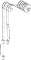
Fig. 1 is a kind of multi-rope winding type stage hoisting machine scheme drawing of the present invention;
Fig. 2 is a kind of multi-rope winding type stage hoisting machine structural representation of the present invention;
Fig. 3 is a kind of multi-rope winding type stage hoisting machine main shaft device structural representation of the present invention.
Fig. 4-the 7th, the operation scheme drawing of a kind of multi-rope winding type stage hoisting machine of the present invention.
Among Fig. 1, Fig. 2 and Fig. 3, the 1-main shaft device; 1.1-rolling bearing pedestal; 1.2-build-up type brake disc; 1.3-dead block; 1.4-plastics lining board; 1.5-rope blocking plate; 1.6-dead block main shaft; 1.7-universal coupling; 1.8-rope-adjusting clutch; The reel 1.9-move about; The reel left wheel hub 1.10-move about; 1.11-two halves brasses; The spool spindle 1.12-move about; The right wheel hub of reel 1.13-move about; The 2-disc brake device; The 3-universal coupling; The 4-Hydraulic Station; The 5-operating console; The 6-electrical motor; The 7-bearing seat; 8-days wheel apparatus; The 9-hoisting cable; The 10-reel top container that moves about; The 11-container at the bottom of the reel that moves about; 12-dead block top container; Container at the bottom of the 13-dead block.
The specific embodiment
As shown in Figure 2: multi-rope winding type stage hoisting machine of the present invention, the synchronous respectively direct connection of two motors 7 is on move about spool spindle 1.12 and dead block main shaft 1.6, whole axis system 1 is driven, main shaft device connects by universal coupling, make spool spindle 1.12 and the dead block main shaft 1.6 that move about realize being synchronized with the movement, 4 disc brake devices 2 that respectively are symmetrically arranged on reel 1.9 and the dead block 1.3 move about, more than control by operating console 5, Hydraulic Station provides braking oil pressure for the multi-rope winding type gig.
As shown in Figure 1: multi-rope winding type stage hoisting machine of the present invention, steel rope is fixed on the main shaft device 1, be connected with dead block top container 12 with the reel top container 10 that moves about by sky wheel apparatus 8, move about reel top container 10 and dead block top container 12 belows hang at the bottom of the reel that moves about container 13 at the bottom of the container 11 and dead block by steel rope again respectively.
As shown in Figure 3: multi-rope winding type stage hoisting machine of the present invention, move about spool spindle 1.12 and dead block main shaft 1.6 in its axis system 1 are fixing by two bearing seats 1.1 respectively, connect by universal coupling 1.7 between two main shafts, make two main shafts to be synchronized with the movement, the reel 1.9 that moves about is installed on the spool spindle of moving about 1.12, dead block 1.3 is installed on the dead block main shaft 1.6, reel 1.9 and the dead block 1.3 two ends build-up type brake disc 1.2 that is connected and fixed that moves about is all inlayed plastics lining board 1.4 on the surface of move about reel 1.9 and dead block 1.3; The reel 1.9 that moves about connects firmly on the left and right wheel hub 1.10,1.13 of the reel that moves about by former, and assembling two halves brasses 1.11 in its left and right wheel hub 1.10,1.13 can not rotate with the spool spindle 1.12 of moving about, and is connected with rope-adjusting clutch 1.8 at the former place; Dead block 1.3 connects firmly on dead block main shaft 1.6 by former, and rotates with main shaft 1.12.
4 steel ropes, one end is separately fixed on the former of move about reel 1.9 and dead block 1.3 both sides with steel rope clamping device, clamping is two on each reel, 1.3 rope blocking plates 1.5 by the middle part of reel 1.9 and dead block that move about are separated into two parts, twine respectively for two steel ropes, the reel 1.9 that moves about is underlap, dead block 1.3 is an overlap, steel rope 9 is connected with dead block top container 12 with the reel top container 10 that moves about by sky wheel apparatus 8, move about reel top container 10 and dead block top container 12 belows hang at the bottom of the reel that moves about container 13 at the bottom of the container 11 and dead block by steel rope again respectively, utilize the difference of main axis rotation direction, steel rope is twined or loosen, with the lifting of finishing the multi-rope winding type gig with transfer work.
Rope-adjusting clutch 1.8 is changed level in order to solve multi level hoisting, and it is long to regulate rope when steel cable extends, and reaches the corresponding accurate stopping of twin containers position.During novel multi-rope winding type gig normal operation, tooth piece and internally toothed annulus in its rope-adjusting clutch 1.8 are in engagement, move about reel 1.9 and two main shaft 1.6,1.12 no relative motions; When transferring rope, high pressure oil enters the clutch block of rope-adjusting clutch 1.8 oil cylinders, passes through driver train, make tooth piece and internally toothed annulus jump out of mesh, the reel 1.9 that moves about produces relative motion with main shaft 1.6,1.12, regulates steel cable length or changes winding level, the purpose that realizes transferring rope; Oil cylinder leaves the high pressure oil oil sump tank in chamber, and by electromagnetic valve, high pressure oil enters the chamber of closing of oil cylinder, by driver train, makes the engagement of tooth piece and internally toothed annulus, the normal service braking state of mechanical recovery.
Disc brake device 2 is to produce braking force by belleville spring, declutches by oil pressure.During novel sinking hoist work, high pressure oil enters oil cylinder, and compression spring makes brake shoe away from brake disc 1.2, makes machine works; Glancing impact, the high pressure oil oil sump tank, the spring force effect makes brake shoe be close to brake disc 1.2, reaches the purpose of braking.
The effect of Hydraulic Station 4 is: for disc brake device 2 provides the pressure oil of different oil pressure value, to obtain different lock torques; , can make the oil pressure of disc brake device 2 drop to a certain value that preliminary election is set up rapidly in the state of accident, after time-delay, whole oil pressure of disc brake device 2 get back to zero rapidly, make disc brake device 2 reach the full application of brake state.
Rolling bearing pedestal 1.1 in addition: adopt the dissection type antifriction-bearing box, it plays a part supporting spindle, reel and other load.
Dead block 1.3: dead block 1.3 is contained on the dead block main shaft 1.6, adopts high strength bolt to connect with dead block main shaft 1.6, and brake disc 1.2 is fixed by bolts to the left and right sides of dead block 1.3.
Reel 1.9 moves about: the reel 1.9 that moves about is contained on the spool spindle 1.12 of moving about.The reel 1.9 that moves about is used Bolt Connection with left and right wheel hub 1.10,1.13, left and right wheel hub 1.10,1.13 is by two halves brasses 1.11 sliding being contained on the spool spindle 1.12 of moving about, the left former of trip tube connects with reamed bolt with rope-adjusting clutch 1.8 wheel hubs, rope-adjusting clutch 1.8 wheel hubs are keyless with spool spindle 1.12 employings of moving about, and brake disc 1.2 is fixed by bolts to the both sides of the reel 1.9 that moves about.
Rope-adjusting clutch 1.8: adopt radial gear block type rope-adjusting clutch.
Brake system: adopted the rearmounted build-up type disc brake device 2 of oil cylinder, the electrical delay two-stage brake hydraulic station.
Shown in Fig. 4-7: the operation scheme drawing of multi-rope winding type stage hoisting machine of the present invention, as Fig. 4, when dead block top container during at pithead position, container is positioned at the well medium position at the bottom of the dead block, and container is arranged in well and bottom hole location at the bottom of move about the reel top container and the reel that moves about.Dead block top container and end container unloading this moment, move about reel top container and end container then load.After this handling process finished, as Fig. 5, container began to transfer at the bottom of dead block top container and the dead block, and container then rises simultaneously at the bottom of move about the reel top container and the reel that moves about.When treating that the dead block top container is transferred in the well position and shaft bottom, the reel top container that moves about is thus lifted to position in pithead position and the well.As shown in Figure 6.At this moment, two containers of the reel that moves about begin unloading, and two containers of dead block then begin to load.Behind the completed loading, as shown in Figure 7, the container of the reel that moves about begins to transfer, and the container of dead block begins to promote.And so forth.
Claims (4)
1. multi-rope winding type stage hoisting machine, comprise axis system, drive motor, transmission device, brake system, Hydraulic Station, handle and indicating system, lifting container and steel rope, it is characterized in that: container and end container two parts headed by lifting container divides, first container is suspended on the reel of main shaft by two steel ropes, end container is suspended under the top container by steel rope, at pit shaft near the chamber of position configuration in stage casing in order to the conversion lifting load, when top container rises to the well head unloading position, end container rises to the chamber at pit shaft middle part, this moment, gig stopped, the top container that load is hung to another reel from low vessels switchover, then by two sections liftings with the load lifting of lifting container to pit shaft.
2. according to the described a kind of multi-rope winding type stage hoisting machine of claim 1, it is characterized in that: described axis system is by two main shafts, universal coupling, form with move about reel and dead block that two main shafts link to each other respectively, two main shafts are linked together by universal coupling, be synchronized with the movement with realization, the reel that moves about is installed on the main shaft, install and fix reel on another root, each reel adopts dividing plate to be divided into the two parts that equate fully, each part is twined steel cable, two steel ropes hang a top container simultaneously, hang one by steel cable again under each top container at the bottom of container.
3. according to the described a kind of multi-rope winding type stage hoisting machine of claim 2, it is characterized in that: the non-shaft coupling side of every main shaft of described axis system all adopts electrical motor directly to connect driving, device is controlled by operating console, and Hydraulic Station provides braking oil pressure for novel multi-rope winding type gig.
4. according to the described a kind of multi-rope winding type stage hoisting machine of claim 2, it is characterized in that: all each is fixed by two rolling bearing pedestals two main shafts in the described axis system, disc brake device is all installed at two reel two ends of installing on main shaft, and mandrel surface is all inlayed plastics lining board; The reel that moves about connects firmly on the left and right wheel hub of the reel that moves about by former, assembling two halves brasses in its left and right wheel hub, and the place is connected with rope-adjusting clutch at former, when throw-out-of clutch, the reel that moves about can not rotate with main shaft, and when power-transfer clutch closed, the reel that moves about can rotate with main shaft; Dead block connects firmly on the dead block main shaft by former, and rotates with main shaft.
Priority Applications (1)
| Application Number | Priority Date | Filing Date | Title |
|---|---|---|---|
| CN2009100662114A CN101693496B (en) | 2009-10-13 | 2009-10-13 | Multi-rope winding type stage hoisting machine |
Applications Claiming Priority (1)
| Application Number | Priority Date | Filing Date | Title |
|---|---|---|---|
| CN2009100662114A CN101693496B (en) | 2009-10-13 | 2009-10-13 | Multi-rope winding type stage hoisting machine |
Publications (2)
| Publication Number | Publication Date |
|---|---|
| CN101693496A true CN101693496A (en) | 2010-04-14 |
| CN101693496B CN101693496B (en) | 2011-09-07 |
Family
ID=42092513
Family Applications (1)
| Application Number | Title | Priority Date | Filing Date |
|---|---|---|---|
| CN2009100662114A Active CN101693496B (en) | 2009-10-13 | 2009-10-13 | Multi-rope winding type stage hoisting machine |
Country Status (1)
| Country | Link |
|---|---|
| CN (1) | CN101693496B (en) |
Cited By (9)
| Publication number | Priority date | Publication date | Assignee | Title |
|---|---|---|---|---|
| CN103241247A (en) * | 2012-02-07 | 2013-08-14 | 刘应国 | Vertical shaft trolley system |
| CN103359647A (en) * | 2012-03-29 | 2013-10-23 | 无锡吊蓝机械制造有限公司 | Double-row-rope synchronous lifting machine of window cleaning machine |
| CN104555675A (en) * | 2014-12-08 | 2015-04-29 | 中信重工机械股份有限公司 | Main elevator shaft device adopting split rolling bearing as traveling winding drum |
| CN104590974A (en) * | 2014-11-28 | 2015-05-06 | 中信重工机械股份有限公司 | Multi-rope composite type mine elevator |
| CN104952348A (en) * | 2015-04-20 | 2015-09-30 | 淮北朔里矿业有限责任公司 | Coal mine hoist simulation training device |
| CN106966282A (en) * | 2017-05-23 | 2017-07-21 | 淮南矿业(集团)有限责任公司 | The flat-tail rope of single lifting system more changing device and its replacing options |
| CN108946415A (en) * | 2018-08-06 | 2018-12-07 | 中国恩菲工程技术有限公司 | Lifting device for mine |
| CN109641721A (en) * | 2016-12-02 | 2019-04-16 | 西马格特宝有限责任公司 | For storing the transportation system in library |
| CN110116952A (en) * | 2019-05-15 | 2019-08-13 | 中国恩菲工程技术有限公司 | Frictional mine hoisting system |
-
2009
- 2009-10-13 CN CN2009100662114A patent/CN101693496B/en active Active
Cited By (10)
| Publication number | Priority date | Publication date | Assignee | Title |
|---|---|---|---|---|
| CN103241247A (en) * | 2012-02-07 | 2013-08-14 | 刘应国 | Vertical shaft trolley system |
| CN103359647A (en) * | 2012-03-29 | 2013-10-23 | 无锡吊蓝机械制造有限公司 | Double-row-rope synchronous lifting machine of window cleaning machine |
| CN104590974A (en) * | 2014-11-28 | 2015-05-06 | 中信重工机械股份有限公司 | Multi-rope composite type mine elevator |
| CN104555675A (en) * | 2014-12-08 | 2015-04-29 | 中信重工机械股份有限公司 | Main elevator shaft device adopting split rolling bearing as traveling winding drum |
| CN104952348A (en) * | 2015-04-20 | 2015-09-30 | 淮北朔里矿业有限责任公司 | Coal mine hoist simulation training device |
| CN109641721A (en) * | 2016-12-02 | 2019-04-16 | 西马格特宝有限责任公司 | For storing the transportation system in library |
| CN106966282A (en) * | 2017-05-23 | 2017-07-21 | 淮南矿业(集团)有限责任公司 | The flat-tail rope of single lifting system more changing device and its replacing options |
| CN106966282B (en) * | 2017-05-23 | 2023-04-18 | 淮南矿业(集团)有限责任公司 | Flat tail rope replacing device of single lifting system and replacing method thereof |
| CN108946415A (en) * | 2018-08-06 | 2018-12-07 | 中国恩菲工程技术有限公司 | Lifting device for mine |
| CN110116952A (en) * | 2019-05-15 | 2019-08-13 | 中国恩菲工程技术有限公司 | Frictional mine hoisting system |
Also Published As
| Publication number | Publication date |
|---|---|
| CN101693496B (en) | 2011-09-07 |
Similar Documents
| Publication | Publication Date | Title |
|---|---|---|
| CN101693496B (en) | Multi-rope winding type stage hoisting machine | |
| CN101665213B (en) | Light-weight rotary hanger for containers | |
| CN101279699A (en) | Novel sinking hoist | |
| CN101234735B (en) | Light-boat-hanging, raft-hanging and goods-hanging three-purpose reel cart for ship | |
| CN101407299B (en) | Double-cylinder articulated multi-rope winding type hoist | |
| CN201458619U (en) | Low-speed assistant hoister | |
| CN203237964U (en) | Shaft sinking and production dual-purpose elevator | |
| CN107311061B (en) | Intelligent traction system of self-locking winch | |
| CN204150995U (en) | Compact, split type DC hoister | |
| CN201241636Y (en) | Hoisting mechanism of rotary digging drill | |
| CN107010521B (en) | A kind of mine hoisting transportation system and method | |
| CN210507375U (en) | Full-balance friction drive type vertical ship lift suitable for heavy-load high-lift application | |
| CN101407300B (en) | Main spindle apparatus of separable double-cylinder single rope winding mine winder | |
| CN202705901U (en) | Hanging beam trolley of hoisting mechanism of railway T-shaped beam bridge girder erection machine | |
| CN214611044U (en) | Multi-oil-cylinder rope adjusting clutch for single-rope winding type hoister | |
| CN110409398B (en) | Full-balance friction-driven vertical ship lift suitable for heavy-load high-lift application | |
| CN209974196U (en) | Safety locking device for mine hoist | |
| CN207647261U (en) | A kind of novel elevating side-sliding packing equipment anti-fall device | |
| CN112960578A (en) | External rotor explosion-proof permanent magnet motor type mining winch with rope arrangement | |
| CN112830371A (en) | Multi-oil-cylinder rope adjusting clutch for single-rope winding type hoister | |
| CN206615946U (en) | Adjustable Winch for mine dispatch | |
| CN111747276A (en) | Large-scale lifting machine of deep vertical shaft | |
| CN111252690A (en) | Double-roller linkage winding type lifting system | |
| CN110921472A (en) | Permanent-magnet direct-drive type mine hoist | |
| CN2934180Y (en) | Detachable two-flap combined drum-winding sinking hoist |
Legal Events
| Date | Code | Title | Description |
|---|---|---|---|
| C06 | Publication | ||
| PB01 | Publication | ||
| C10 | Entry into substantive examination | ||
| SE01 | Entry into force of request for substantive examination | ||
| C14 | Grant of patent or utility model | ||
| GR01 | Patent grant |