CN101657942A - electrical connector - Google Patents
electrical connector Download PDFInfo
- Publication number
- CN101657942A CN101657942A CN200780052455A CN200780052455A CN101657942A CN 101657942 A CN101657942 A CN 101657942A CN 200780052455 A CN200780052455 A CN 200780052455A CN 200780052455 A CN200780052455 A CN 200780052455A CN 101657942 A CN101657942 A CN 101657942A
- Authority
- CN
- China
- Prior art keywords
- electric connector
- contact
- sheath
- connector
- connecting element
- Prior art date
- Legal status (The legal status is an assumption and is not a legal conclusion. Google has not performed a legal analysis and makes no representation as to the accuracy of the status listed.)
- Pending
Links
Images


Classifications
-
- H—ELECTRICITY
- H01—ELECTRIC ELEMENTS
- H01R—ELECTRICALLY-CONDUCTIVE CONNECTIONS; STRUCTURAL ASSOCIATIONS OF A PLURALITY OF MUTUALLY-INSULATED ELECTRICAL CONNECTING ELEMENTS; COUPLING DEVICES; CURRENT COLLECTORS
- H01R13/00—Details of coupling devices of the kinds covered by groups H01R12/70 or H01R24/00 - H01R33/00
- H01R13/44—Means for preventing access to live contacts
- H01R13/447—Shutter or cover plate
- H01R13/453—Shutter or cover plate opened by engagement of counterpart
- H01R13/4538—Covers sliding or withdrawing in the direction of engagement
-
- H—ELECTRICITY
- H01—ELECTRIC ELEMENTS
- H01R—ELECTRICALLY-CONDUCTIVE CONNECTIONS; STRUCTURAL ASSOCIATIONS OF A PLURALITY OF MUTUALLY-INSULATED ELECTRICAL CONNECTING ELEMENTS; COUPLING DEVICES; CURRENT COLLECTORS
- H01R13/00—Details of coupling devices of the kinds covered by groups H01R12/70 or H01R24/00 - H01R33/00
- H01R13/46—Bases; Cases
- H01R13/502—Bases; Cases composed of different pieces
- H01R13/506—Bases; Cases composed of different pieces assembled by snap action of the parts
-
- H—ELECTRICITY
- H01—ELECTRIC ELEMENTS
- H01R—ELECTRICALLY-CONDUCTIVE CONNECTIONS; STRUCTURAL ASSOCIATIONS OF A PLURALITY OF MUTUALLY-INSULATED ELECTRICAL CONNECTING ELEMENTS; COUPLING DEVICES; CURRENT COLLECTORS
- H01R13/00—Details of coupling devices of the kinds covered by groups H01R12/70 or H01R24/00 - H01R33/00
- H01R13/58—Means for relieving strain on wire connection, e.g. cord grip, for avoiding loosening of connections between wires and terminals within a coupling device terminating a cable
- H01R13/5841—Means for relieving strain on wire connection, e.g. cord grip, for avoiding loosening of connections between wires and terminals within a coupling device terminating a cable allowing different orientations of the cable with respect to the coupling direction
-
- H—ELECTRICITY
- H01—ELECTRIC ELEMENTS
- H01R—ELECTRICALLY-CONDUCTIVE CONNECTIONS; STRUCTURAL ASSOCIATIONS OF A PLURALITY OF MUTUALLY-INSULATED ELECTRICAL CONNECTING ELEMENTS; COUPLING DEVICES; CURRENT COLLECTORS
- H01R2201/00—Connectors or connections adapted for particular applications
- H01R2201/16—Connectors or connections adapted for particular applications for telephony
-
- H—ELECTRICITY
- H01—ELECTRIC ELEMENTS
- H01R—ELECTRICALLY-CONDUCTIVE CONNECTIONS; STRUCTURAL ASSOCIATIONS OF A PLURALITY OF MUTUALLY-INSULATED ELECTRICAL CONNECTING ELEMENTS; COUPLING DEVICES; CURRENT COLLECTORS
- H01R24/00—Two-part coupling devices, or either of their cooperating parts, characterised by their overall structure
- H01R24/60—Contacts spaced along planar side wall transverse to longitudinal axis of engagement
-
- H—ELECTRICITY
- H01—ELECTRIC ELEMENTS
- H01R—ELECTRICALLY-CONDUCTIVE CONNECTIONS; STRUCTURAL ASSOCIATIONS OF A PLURALITY OF MUTUALLY-INSULATED ELECTRICAL CONNECTING ELEMENTS; COUPLING DEVICES; CURRENT COLLECTORS
- H01R4/00—Electrically-conductive connections between two or more conductive members in direct contact, i.e. touching one another; Means for effecting or maintaining such contact; Electrically-conductive connections having two or more spaced connecting locations for conductors and using contact members penetrating insulation
- H01R4/24—Connections using contact members penetrating or cutting insulation or cable strands
- H01R4/2416—Connections using contact members penetrating or cutting insulation or cable strands the contact members having insulation-cutting edges, e.g. of tuning fork type
- H01R4/242—Connections using contact members penetrating or cutting insulation or cable strands the contact members having insulation-cutting edges, e.g. of tuning fork type the contact members being plates having a single slot
- H01R4/2425—Flat plates, e.g. multi-layered flat plates
- H01R4/2429—Flat plates, e.g. multi-layered flat plates mounted in an insulating base
-
- H—ELECTRICITY
- H01—ELECTRIC ELEMENTS
- H01R—ELECTRICALLY-CONDUCTIVE CONNECTIONS; STRUCTURAL ASSOCIATIONS OF A PLURALITY OF MUTUALLY-INSULATED ELECTRICAL CONNECTING ELEMENTS; COUPLING DEVICES; CURRENT COLLECTORS
- H01R9/00—Structural associations of a plurality of mutually-insulated electrical connecting elements, e.g. terminal strips or terminal blocks; Terminals or binding posts mounted upon a base or in a case; Bases therefor
- H01R9/22—Bases, e.g. strip, block, panel
- H01R9/24—Terminal blocks
Abstract
An electrical connector (100) comprises the following: (a) a first element (102) having an opening (114) for receiving an electrical cable (116), (b) a second element (104, 106) coupled to an electrical connector element (108), wherein the first element is coupled to the second element in order to define a cavity between the first and the second elements, wherein the connector element is in electrical contact with the cable in the cavity, and (c) an adjustable insulating shield (110) that is movable between a first position and a second position relative to the second element, such that a conductive contact section of the connector element is exposed for direct contact when the shield is moved to the first position, and that the shield covers the section in order to restrict direct accessto the section when the shield is moved to the second position.
Description
Technical field
The present invention relates to electric connector.
Background technology
The electric connector that is connected with cable provides a kind of instrument easily that can be electrically connected or disconnect electrical connection with cable.In order to be electrically connected, electric connector can have the contact of exposure.Yet, when the user uses the electric connector of the contact with exposure, have sizable danger, and especially exist the user to contact and the danger of electrocuting that causes with the exposure contact of the connector that is used to power.
Expectation provides a kind of electric connector that overcomes above-mentioned one or more problem, and the useful possibility to existing electric connector perhaps is provided at least.
Summary of the invention
According to a kind of electric connector that provides of the present invention, comprising:
(a) first member, it comprises the opening that is used to receive cable;
(b) second member that links to each other with electrical connector element, described first member are connected to described second member to limit the cavity volume between described first member and described second member, and described connecting element electrically contacts with described cable in described cavity volume; And
(c) adjustable insulating sleeve, described adjustable insulating sleeve can move between a primary importance and a second place with respect to described second member, so that when described sheath moves to described primary importance, the electrically conducting contact of described connecting element is exposed so that directly contact, when described sheath moved to the described second place, described sheath covered described electrically conducting contact and contacts with the direct of described electrically conducting contact with restriction.
According to a further aspect in the invention, provide a kind of plug that is used for a plurality of insulated electric conductors of electric data cable are electrically connected to the respective contacts of connector modules, comprised
(a) housing, described housing is shaped to receive the insulated electric conductor of described data cable;
(b) electrical connector element, described electrical connector element comprise second end that is connected to described housing and be used for first end that engages with corresponding conductor electricity and be used for described conductor is electrically connected with the corresponding contact of described connector modules;
(c) adjustable insulating sleeve,
Wherein, described sheath is suitable for moving between a primary importance and a second place, and in described primary importance, the second end electric insulation of described connecting element is to prevent outside contact, and in the described second place, conduction exposes described contact elements so that electrically contact contact to described connector modules.
Description of drawings
At this with reference to the accompanying drawings, only the preferred embodiments of the present invention are described by example:
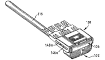
Fig. 1 is the exploded view of electric connector of the present invention;
Fig. 2 is that sheath is in the not perspective view of the electric connector of termination location;
Fig. 3 is the perspective view that sheath is in the electric connector of retrieving position;
Fig. 4 is the perspective view that sheath is in the electric connector of termination location;
Fig. 5,6 and 7 is respectively vertical view, end view and the perspective view with the electric connector of first make arrangement;
Fig. 8,9 and 10 is respectively vertical view, end view and the perspective view with the electric connector of second make arrangement.
Embodiment
As shown in Figure 1, electric connector 100 comprises first member 102, second member (being made up of last side body 106 and following side body 104), electrical connector element 108, insulating sleeve 110 and pushing utensil 112.First member 102 comprises the opening 114 that is used to receive from one or more leads of cable 116.Electric connector 100 can be used for the cable 106 of any kind.For example, cable 116 can be single-core cable or have multicore cable with the corresponding lead of one or more twisted cables,
The last side body 106 of first member 102 and second member defines the cavity volume between member 102 and 106 when connecting together.The last side body 106 of second member comprises one or more metallic channels 122, and each metallic channel is used to receive the peeling end from the lead of the correspondence of cable 116.When the peeling end of lead was held in place by metallic channel 122, the contact groove 124 that forms on the electrical connector element 108 can close with the corresponding peeling termination of lead in described cavity volume, electrically contacts with foundation.For example, each contact groove 124 comprises the surface of being made by electric conducting material (for example copper), so that directly contact and be electrically connected with the peeling end of the lead (not shown) that is held in place by conductive trough 122.The size of each contact groove 124 is enough to little of making the peeling end that firmly grasps lead.Connecting element 108 comprises one or more fingers 126, and each finger 126 has the contact site 128 that is used to electrically contact.Connecting element 108 roughly is smooth, and connecting element is formed with conductive path at upper surface 130 and/or on lower surface 132, with the electrical connection between the corresponding contact site 128 that each contact groove 124 and finger 126 are provided.Connecting element 108 preferably one or both sides 130,132 on etching the printed circuit board (PCB) of conductive path is arranged.In the structure of Fig. 1, the contact groove 124 that is used to receive the lead of twisted cable is connected to corresponding contact site 128 on the adjacent finger 126 by conductive path.Connecting element 108 is configured to and last side body 106 coupling assemblings.Connecting element 108 comprises one or more locating notches (retaining notch) 134a and 134b, and the corresponding location indentations 136 that forms in described locating notch and the last side body 106 engages, so that member 106 and 108 is firmly connected together.Last side body has one or more protuberance 138a, 138b, 138c, 138d and 138e, described protuberance engages with corresponding recess 140a, 140b, 140c, 140d and the 140e of formation in the following side body 104, thereby member 104 and 106 is firmly connected together.
Adjustable insulating sleeve 110 is made by non-conducting material (for example PVC), and is formed with one or more guiding groove 146a and 146b in sheath 110.In one embodiment, as shown in Figure 1, guiding groove 146a and 146b are formed the wall by sheath 110.In another embodiment, guiding groove 146a and 146b are the recesses that forms on the inner surface of sheath 110, rather than are formed by the wall of sheath 110. Guiding groove 146a and 146b engage with the corresponding guiding protuberance 148a and 148 that forms on the outer surface of following side body 104, thereby sheath 110 can move by the mode of sliding with respect to second member 104,106, and moving through of sheath 110 guides protuberance 148a and 148b to be directed.Guiding protuberance 148a and 148b long enough are to keep the stability of sheath 110 in the process that moves.
Sheath 110 can move between the primary importance and the second place along the length of second member 104,106, thereby when sheath 110 moved to primary importance, the contact site 128 of finger 126 is exposed so that directly contact.When sheath 110 moved to the second place, this sheath covered the contact site 128 of finger 126, contacts to minimize with the direct of contact site 128.
Electric connector 100 comprises the pushing utensil 112 that makes sheath 110 shift to the second place.Pushing utensil 112 comprises any type of compression spring, and as shown in Figure 1 S shape spring preferably.Pushing utensil 112 and pushes utensil 112 backups and down the wall 144 of side body 104 and the inwall of sheath 110 between the following side body 104 of sheath 110 and second member, so that sheath 110 is pushed towards the second place.
Fig. 2 is the perspective view that sheath 110 is in the electric connector 100 of the second place (promptly not termination location).The perspective view of Fig. 3 electric connector 100 that to be the sheath 110 that is in the part retrieving position move towards primary importance.Fig. 4 is the perspective view that sheath 110 is in the electric connector 100 of primary importance (being termination location).Same Reference numeral representative and identical as shown in Figure 1 parts among Fig. 2,3 and 4.
Multiple remodeling is conspicuous in the protection scope of the present invention that does not break away from conjunction with the accompanying drawings for a person skilled in the art.
Any public technology (information of perhaps therefrom obtaining) before of mentioning in this manual, perhaps any known fact, it or not the part of the general knowledge of the related aspect of this specification, not will be understood that to the public technology (the perhaps information of obtaining from kind) before any a part a kind of that perhaps any known fact has constituted the general knowledge of the related aspect of this specification admits, confession or any type of hint yet.
Claims (17)
1, a kind of electric connector comprises:
(a) first member, it comprises the opening that is used to receive cable;
(b) be connected to second member of electrical connector element, described first member links to each other with described second member to limit the cavity volume between described first member and described second member, and described connecting element electrically contacts with described cable in described cavity volume;
(c) adjustable insulating sleeve, it can move between a primary importance and a second place with respect to described second member, make when described sheath moves to described primary importance, the electrically conducting contact of described connecting element is exposed so that directly contact, and when described sheath moved to the described second place, described sheath covered described electrically conducting contact and contacts with the direct of described electrically conducting contact with restriction.
2, electric connector as claimed in claim 1 is characterized in that, also comprises being used to pushing utensil that described sheath is moved towards the described second place.
3, electric connector as claimed in claim 2 is characterized in that, described pushing utensil comprises the compression spring.
4, electric connector as claimed in claim 3 is characterized in that, described compression spring comprises S shape spring, and described spring is between described sheath and described second member.
5, electric connector as claimed in claim 1 is characterized in that, described sheath moves along the length of described second member.
6, electric connector as claimed in claim 1, it is characterized in that, described sheath comprises one or more guiding grooves, the one or more guiding protuberances that cooperate in described guiding groove that move through of described sheath are directed, and each the guiding protuberance in wherein said one or more guiding protuberances forms on the outer surface of described second member.
7, electric connector as claimed in claim 1 is characterized in that, described first member and second member connect together by the recess that forms on the breech lock utensil that forms on one in described member and in described member another.
8, electric connector as claimed in claim 7 is characterized in that, described breech lock utensil comprises the resilient latch lock of the head with expansion, and the head of described expansion engages with described recess so that described first member and second member are firmly kept together.
9, electric connector as claimed in claim 1, it is characterized in that, after described first member and described second member were rotated relative to one another along separately plane parallel to each other, described first member can connect together with one or more different orientation with described second member.
10, electric connector as claimed in claim 1 is characterized in that, described connecting element is set to the coupling assembling with described second member.
11, electric connector as claimed in claim 1, it is characterized in that, described connecting element comprises one or more contact grooves, so as when the lead of the correspondence in described cable to receive in described contact groove and described lead electrically contact, described connecting element comprises corresponding conductive path, the contact site of the correspondence that the finger that described conductive path extends to described connecting element from each described contact groove forms.
12, electric connector as claimed in claim 1 is characterized in that, described connecting element is a printed circuit board (PCB).
13, the arbitrary described electric connector of claim as described above is characterized in that, also comprises being used to the securing member that prevents that sheath from moving towards primary importance from the second place.
14, electric connector as claimed in claim 13 is characterized in that, described securing member is a breech lock.
15, a kind of plug that is used for a plurality of insulated electric conductors of electric data cable are electrically connected to the corresponding contact of connector modules comprises:
(a) housing, described housing are shaped as the insulated electric conductor that receives described data cable;
(b) electrical connector element, it comprises second end that links to each other with described housing and be used for first end that engages with corresponding described conductor electricity and be used for described conductor is electrically connected with the corresponding described contact of described connector modules;
(c) adjustable insulating sleeve,
It is characterized in that, described sheath is suitable for moving between a primary importance and a second place, and in described primary importance, second end of described connecting element is contacted to prevent the outside by electric insulation, in the described second place, the contact element conduction that electrically contacts with the contact of described connector modules exposes.
16, a kind of with reference to accompanying drawing such as the described electric connector of specification.
17, a kind of with reference to accompanying drawing such as the described plug of specification.
Applications Claiming Priority (2)
| Application Number | Priority Date | Filing Date | Title |
|---|---|---|---|
| AU2007901719 | 2007-03-30 | ||
| AU2007901719A AU2007901719A0 (en) | 2007-03-30 | An electrical connector |
Publications (1)
| Publication Number | Publication Date |
|---|---|
| CN101657942A true CN101657942A (en) | 2010-02-24 |
Family
ID=38573314
Family Applications (1)
| Application Number | Title | Priority Date | Filing Date |
|---|---|---|---|
| CN200780052455A Pending CN101657942A (en) | 2007-03-30 | 2007-07-18 | electrical connector |
Country Status (5)
| Country | Link |
|---|---|
| US (1) | US8002555B2 (en) |
| EP (1) | EP2143175A1 (en) |
| CN (1) | CN101657942A (en) |
| AU (1) | AU2007350603B2 (en) |
| WO (1) | WO2008119370A1 (en) |
Cited By (1)
| Publication number | Priority date | Publication date | Assignee | Title |
|---|---|---|---|---|
| CN103890862A (en) * | 2011-10-18 | 2014-06-25 | 矢崎总业株式会社 | Conductive path |
Families Citing this family (8)
| Publication number | Priority date | Publication date | Assignee | Title |
|---|---|---|---|---|
| US8113888B2 (en) | 2008-05-15 | 2012-02-14 | Adc Gmbh | Circuit board for electrical connector and electrical connector |
| WO2010022436A1 (en) * | 2008-08-29 | 2010-03-04 | Adc Gmbh | Electrical connector having movable protective shield |
| EP2705575B1 (en) * | 2011-05-03 | 2017-04-12 | CardioInsight Technologies, Inc. | High-voltage resistance for a connector attached to a circuit board |
| EP2795742A4 (en) | 2011-12-23 | 2015-08-12 | Tyco Electronics Services Gmbh | Telecommunications cabling system, and electrical connection module and shielding interface therefor |
| DE102015211027A1 (en) * | 2015-06-16 | 2016-12-22 | Zf Friedrichshafen Ag | Chip protection for printed circuit boards |
| CN205029121U (en) * | 2015-09-10 | 2016-02-10 | 番禺得意精密电子工业有限公司 | Cable connecting device and electric connector's combination |
| US10644441B2 (en) * | 2017-05-31 | 2020-05-05 | Horizon Co., Ltd. | Cable |
| JP7265461B2 (en) * | 2019-09-26 | 2023-04-26 | 住友電装株式会社 | Power supply device and branch connector device |
Family Cites Families (10)
| Publication number | Priority date | Publication date | Assignee | Title |
|---|---|---|---|---|
| DE3330177C2 (en) | 1983-08-20 | 1985-11-14 | Filmosto-Projektion Johannes Jost Gmbh & Co, 4300 Essen | Electric plug with child lock |
| US4959021A (en) | 1988-04-12 | 1990-09-25 | Byrne Norman R | Pivotable power feed connector |
| GB2242080B (en) | 1990-03-09 | 1994-12-21 | Krone Ag | Electrical connectors |
| US5718604A (en) * | 1996-03-13 | 1998-02-17 | Lucent Technologies Inc. | Patch cord connection system |
| US6159020A (en) | 1999-04-16 | 2000-12-12 | Lucent Technologies Inc. | Anti-snag patchcord plug latch and cover |
| US6231358B1 (en) | 2000-01-06 | 2001-05-15 | Angelo Fan Brace Licensing, L.L.C. | Electrical plug and receptacle having safety features |
| AU2002950339A0 (en) | 2002-07-23 | 2002-09-12 | Krone Gmbh | Patch cord connector |
| US7503799B2 (en) * | 2006-08-28 | 2009-03-17 | Commscope Inc. | Communications plug with reverse cordage and anti-snag configuration |
| AU314729S (en) | 2007-03-30 | 2007-06-19 | Tyco Electronics Services Gmbh | Patch plug |
| AU314730S (en) | 2007-03-30 | 2007-06-19 | Tyco Electronics Services Gmbh | Patch plug |
-
2007
- 2007-07-18 AU AU2007350603A patent/AU2007350603B2/en not_active Ceased
- 2007-07-18 CN CN200780052455A patent/CN101657942A/en active Pending
- 2007-07-18 EP EP07786143A patent/EP2143175A1/en not_active Withdrawn
- 2007-07-18 US US12/593,939 patent/US8002555B2/en not_active Expired - Fee Related
- 2007-07-18 WO PCT/EP2007/006369 patent/WO2008119370A1/en active Application Filing
Cited By (2)
| Publication number | Priority date | Publication date | Assignee | Title |
|---|---|---|---|---|
| CN103890862A (en) * | 2011-10-18 | 2014-06-25 | 矢崎总业株式会社 | Conductive path |
| US9337565B2 (en) | 2011-10-18 | 2016-05-10 | Yazaki Corporation | Conductive path |
Also Published As
| Publication number | Publication date |
|---|---|
| AU2007350603B2 (en) | 2011-09-15 |
| AU2007350603A1 (en) | 2008-10-09 |
| US8002555B2 (en) | 2011-08-23 |
| WO2008119370A1 (en) | 2008-10-09 |
| US20100048059A1 (en) | 2010-02-25 |
| EP2143175A1 (en) | 2010-01-13 |
Similar Documents
| Publication | Publication Date | Title |
|---|---|---|
| CN101657942A (en) | electrical connector | |
| CN106229725B (en) | Modular radio frequency connector system | |
| CN101443963B (en) | Connector | |
| TW201112548A (en) | Electrical connector system | |
| RU2339133C1 (en) | Mounting system with cutting isolation for two electric conductors | |
| US9865960B2 (en) | Coupler connector and cable terminator with side contacts | |
| TW201115861A (en) | RJ-45 style communications jacks that are configured to receive both RJ-45 and RJ-11 style communications plugs | |
| US20160240986A1 (en) | Communication outlet with shutter mechanism and wire manager | |
| JPS5936387B2 (en) | connector | |
| WO2008137106A3 (en) | Insulation displacement crimp connector | |
| US5564940A (en) | Electrical connector having a conductor holding block | |
| CN217823361U (en) | Bus duct and power distribution system | |
| CN109428227B (en) | Connecting device with floatable self-adjusting contact point and connecting method thereof | |
| JPH03133075A (en) | Low insertion type electric connector | |
| CN110739556B (en) | Connector with quick wire locking structure | |
| US7097513B2 (en) | Telecommunication connector | |
| JP3179678U (en) | Socket that can prevent plug terminals from coming off | |
| US8162679B2 (en) | Insulation displacement contact and electric connector using the same | |
| JP6117481B2 (en) | Assembly parts for connectors, alignment plates and cable connectors | |
| TWM249341U (en) | Modular jack | |
| CN101350462B (en) | Structure for electric connector | |
| CN107425344B (en) | Connector | |
| JPH0546671B2 (en) | ||
| JP3009831B2 (en) | Improved connector retention block for electrical connectors | |
| CN102456955B (en) | Bridging structure for wire terminal |
Legal Events
| Date | Code | Title | Description |
|---|---|---|---|
| C06 | Publication | ||
| PB01 | Publication | ||
| C10 | Entry into substantive examination | ||
| SE01 | Entry into force of request for substantive examination | ||
| C02 | Deemed withdrawal of patent application after publication (patent law 2001) | ||
| WD01 | Invention patent application deemed withdrawn after publication |
Application publication date: 20100224 |