CN101640407A - Power conversion device and method - Google Patents
Power conversion device and method Download PDFInfo
- Publication number
- CN101640407A CN101640407A CN200810134768A CN200810134768A CN101640407A CN 101640407 A CN101640407 A CN 101640407A CN 200810134768 A CN200810134768 A CN 200810134768A CN 200810134768 A CN200810134768 A CN 200810134768A CN 101640407 A CN101640407 A CN 101640407A
- Authority
- CN
- China
- Prior art keywords
- voltage
- power conversion
- coupled
- circuit
- conversion device
- Prior art date
- Legal status (The legal status is an assumption and is not a legal conclusion. Google has not performed a legal analysis and makes no representation as to the accuracy of the status listed.)
- Granted
Links
Images


Classifications
-
- H—ELECTRICITY
- H02—GENERATION; CONVERSION OR DISTRIBUTION OF ELECTRIC POWER
- H02H—EMERGENCY PROTECTIVE CIRCUIT ARRANGEMENTS
- H02H7/00—Emergency protective circuit arrangements specially adapted for specific types of electric machines or apparatus or for sectionalised protection of cable or line systems, and effecting automatic switching in the event of an undesired change from normal working conditions
- H02H7/10—Emergency protective circuit arrangements specially adapted for specific types of electric machines or apparatus or for sectionalised protection of cable or line systems, and effecting automatic switching in the event of an undesired change from normal working conditions for converters; for rectifiers
- H02H7/12—Emergency protective circuit arrangements specially adapted for specific types of electric machines or apparatus or for sectionalised protection of cable or line systems, and effecting automatic switching in the event of an undesired change from normal working conditions for converters; for rectifiers for static converters or rectifiers
- H02H7/125—Emergency protective circuit arrangements specially adapted for specific types of electric machines or apparatus or for sectionalised protection of cable or line systems, and effecting automatic switching in the event of an undesired change from normal working conditions for converters; for rectifiers for static converters or rectifiers for rectifiers
- H02H7/1252—Emergency protective circuit arrangements specially adapted for specific types of electric machines or apparatus or for sectionalised protection of cable or line systems, and effecting automatic switching in the event of an undesired change from normal working conditions for converters; for rectifiers for static converters or rectifiers for rectifiers responsive to overvoltage in input or output, e.g. by load dump
-
- H—ELECTRICITY
- H02—GENERATION; CONVERSION OR DISTRIBUTION OF ELECTRIC POWER
- H02H—EMERGENCY PROTECTIVE CIRCUIT ARRANGEMENTS
- H02H7/00—Emergency protective circuit arrangements specially adapted for specific types of electric machines or apparatus or for sectionalised protection of cable or line systems, and effecting automatic switching in the event of an undesired change from normal working conditions
- H02H7/16—Emergency protective circuit arrangements specially adapted for specific types of electric machines or apparatus or for sectionalised protection of cable or line systems, and effecting automatic switching in the event of an undesired change from normal working conditions for capacitors
Landscapes
- Engineering & Computer Science (AREA)
- Power Engineering (AREA)
- Dc-Dc Converters (AREA)
- Rectifiers (AREA)
- Inverter Devices (AREA)
Abstract
Description
技术领域 technical field
本发明有关一种电源转换装置与方法,特别是一种具有过电压保护的电源转换装置与方法。The present invention relates to a power conversion device and method, in particular to a power conversion device and method with overvoltage protection.
背景技术 Background technique
具有电源转换装置(adapter)的电脑系统(如:笔记本电脑),通过电源转换装置接收交流电后,将属于交流电压的交流电转换为电脑系统所需的直流电压。先前技术中,电子产品销售市场的反应,经常有电脑系统中电源转换装置因损坏而遭退回的情况发生。经分析发现,大多为电源转换装置中的大型电容(bulk capacitor)烧毁,且大多数发生的地点,集中在配电系统较不稳定且交流电较高的区域,例如:中国、印度等。由于电源转换装置须接收交流电,因此当交流电不稳定时,若所接收的交流电的电压值突然升高,而超过大型电容所能承受的耐压,便会造成大型电容的烧毁,进而使电源转换装置损坏。A computer system (such as a notebook computer) with a power conversion device (adapter) converts the AC voltage belonging to the AC voltage into the DC voltage required by the computer system after receiving the AC power through the power conversion device. In the prior art, the reaction of the electronic product sales market is that the power conversion device in the computer system is often returned due to damage. After analysis, it was found that most of the bulk capacitors in the power conversion device were burned, and most of the occurrences were concentrated in areas with unstable power distribution systems and high AC power, such as China and India. Since the power conversion device needs to receive AC power, when the AC power is unstable, if the voltage value of the received AC power suddenly rises and exceeds the withstand voltage of the large capacitor, it will cause the large capacitor to burn out, thereby causing the power conversion The device is damaged.
此外,当电源转换装置的电源插头与交流电插座连接时,由于插电的瞬间,大型电容处于短路状态,因此会有很高的侵入电流(inrush current)产生。由于插电瞬间产生了大电流值的侵入电流,因此使得火花于瞬间产生。如此,不仅容易令使用者感到危险,且电源转换装置的电源插头更会因火花而造成锈蚀,而损坏其电源插头。In addition, when the power plug of the power conversion device is connected to an AC outlet, since the large capacitor is in a short-circuit state at the moment of plugging in, a high inrush current will be generated. Since the intrusion current with a large current value is generated at the moment of plugging in, the spark is generated in an instant. In this way, not only is it easy to make the user feel dangerous, but also the power plug of the power conversion device will be rusted due to sparks, and the power plug will be damaged.
发明内容 Contents of the invention
有鉴于此本发明提出一种电源转换装置与方法。利用本发明所提出的装置与方法,当交流电电压过大时,停止交流电供应至电源转换装置,如此可解决因交流电的电压过高而造成大型电容(bulk capacitor)的烧毁。再者,当电源转换装置与交流电连接的一瞬间,避免让交流电于瞬间直接进入大型电容,如此可解决瞬间产生火花的问题。In view of this, the present invention proposes a power conversion device and method. With the device and method proposed by the present invention, when the voltage of the AC power is too high, the supply of the AC power to the power conversion device is stopped, so that the burning of the bulk capacitor caused by the high voltage of the AC power can be solved. Furthermore, when the power conversion device is connected to the AC power for a moment, the AC power is prevented from entering the large capacitor directly, which can solve the problem of instantaneous sparks.
本发明提出一种电源转换装置(adapter),转换交流电压为直流电压而提供予负载,该电源转换装置包含:滤波电路、整流电路、大型电容、变压器及过电压保护电路。滤波电路接收交流电压,滤波交流电压而产生滤波电压。整流电路耦接滤波电路,接收滤波电压,整流滤波电压而产生整流电压。大型电容耦接整流电路,接收整流电压而产生输出电压。变压器具有一次侧与二次侧,一次侧耦接大型电容而接收输出电压,二次侧产生直流电压并耦接负载。过电压保护电路耦接于滤波电路与大型电容之间,当交流电压的电压值大于预设值,过电压保护电路关闭,使大型电容与交流电压之间呈现断路。The present invention provides a power conversion device (adapter), which converts AC voltage to DC voltage and provides it to a load. The power conversion device includes: a filter circuit, a rectifier circuit, a large capacitor, a transformer and an overvoltage protection circuit. The filter circuit receives the AC voltage and filters the AC voltage to generate a filter voltage. The rectification circuit is coupled to the filter circuit, receives the filter voltage, and rectifies the filter voltage to generate a rectified voltage. The large capacitor is coupled to the rectification circuit to receive the rectified voltage to generate an output voltage. The transformer has a primary side and a secondary side. The primary side is coupled to a large capacitor to receive an output voltage, and the secondary side generates a DC voltage and is coupled to a load. The overvoltage protection circuit is coupled between the filter circuit and the large capacitor. When the voltage value of the AC voltage is greater than a preset value, the overvoltage protection circuit is turned off, so that there is an open circuit between the large capacitor and the AC voltage.
本发明亦提出一种电源转换方法,转换交流电压为直流电压而提供予负载,包含下列步骤:接收交流电压,滤波交流电压而产生滤波电压;接收滤波电压,整流滤波电压而产生整流电压;提供大型电容,接收整流电压而产生输出电压;提供具有一次侧与二次侧的一变压器,一次侧耦接大型电容而接收输出电压,二次侧产生直流电压并耦接负载;侦测交流电压,当交流电压的电压值大于预设值,使大型电容与交流电压之间呈现断路。The present invention also proposes a power conversion method, which converts an AC voltage into a DC voltage and provides it to a load, including the following steps: receiving the AC voltage, filtering the AC voltage to generate a filtered voltage; receiving the filtered voltage, rectifying the filtered voltage to generate a rectified voltage; providing A large capacitor receives the rectified voltage to generate an output voltage; provides a transformer with a primary side and a secondary side, the primary side is coupled to the large capacitor to receive the output voltage, and the secondary side generates a DC voltage and is coupled to the load; detects the AC voltage, When the voltage value of the AC voltage is greater than the preset value, an open circuit appears between the large capacitor and the AC voltage.
有关本发明的较佳实施例及其功效,兹配合附图说明如后。The preferred embodiments of the present invention and their effects are described below in conjunction with the accompanying drawings.
附图说明 Description of drawings
图1所示为电源转换装置的第一实施例示意图。FIG. 1 is a schematic diagram of a first embodiment of a power conversion device.
图2所示为电源转换装置的第二实施例示意图。FIG. 2 is a schematic diagram of a second embodiment of the power conversion device.
图3所示为电源转换装置的第三实施例示意图。FIG. 3 is a schematic diagram of a third embodiment of the power conversion device.
图4所示为电源转换装置的第四实施例示意图。FIG. 4 is a schematic diagram of a fourth embodiment of a power conversion device.
图5所示为电源转换装置的第五实施例示意图。FIG. 5 is a schematic diagram of a fifth embodiment of the power conversion device.
图6所示电源转换方法的流程图。The flowchart of the power conversion method shown in FIG. 6 .
具体实施方式 Detailed ways
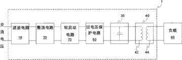
请参照图1,该图所示为电源转换装置的第一实施例示意图。本发明所提出的电源转换装置1转换交流电压为直流电压而提供予负载60,电源转换装置1包含:滤波电路10、整流电路20、大型电容30、变压器40、过电压保护电路50。Please refer to FIG. 1 , which is a schematic diagram of a first embodiment of a power conversion device. The
滤波电路10接收交流电所提供的交流电压,将交流电压滤波后产生滤波电压。其中,滤波电路10可为RC滤波器或LC滤波器等,但不以此为限。整流电路20耦接滤波电路10,接收滤波电路10所传送的滤波电压,经整流滤波电压后产生整流电压。其中,整流电路20可分为半波整流与全波整流,可利用二极管顺向电压导通而逆向电压截止的特性,达到整流的目的,但不以为限。The
大型电容(bulk capacitor)30耦接整流电路20,接收整流电路20所传送的整流电压,而产生输出电压。由于电容为储能元件,在整流电路20整流期间,亦即当整流电路20的二极管导通时,大型电容30会同时充电并储存电荷,此时若没有设置大型电容30,当整流电路20的二极管截止或电压降低时,所产生的电压便会随之降低,形成所谓的涟波电压而非平稳的直流电压。因此,通过大型电容30,当整流电路20的二极管截止或电压降低时,大型电容30便会进行放电,如此可减缓电压的下降。所以,电源转换装置(adapter)1中设置大型电容30,可用以减少涟波(ripple)对电路的影响,而获得平稳的输出电压,进而使传送至负载60的电压为一稳定的直流电压。A bulk capacitor (bulk capacitor) 30 is coupled to the
变压器40具有一次侧42与二次侧44,一次侧42耦接大型电容30,二次侧44耦接负载60。变压器40接收大型电容30所产生的输出电压而产生负载60所需的直流电压。The
过电压保护电路(over voltage protection,OVP)50耦接滤波电路10与大型电容30之间,当交流电压的电压值大于预设值,过电压保护电路50便会关闭,使大型电容30与交流电压之间呈现断路。由此可知,过电压保护电路50位于变压器40的一次侧42,且主要用以保护大型电容30,使大型电容30不会因为交流电压的不稳定而突然升高,造成大型电容30的烧毁。此与一般已知技术中,过电压保护电路大多位于变压器的二次侧,而用以保护负载的方式有所不同。An over voltage protection circuit (over voltage protection, OVP) 50 is coupled between the
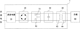
请参照图2为电源转换装置的第二实施例示意图。于此,过电压保护电路50可包含MOS晶体管开关52。其中,MOS晶体管开关52可为高压型MOS晶体管,如此可承受较高的电压,进而保护大型电容30。当交流电压的电压值小于预设值时,也就是处于正常状态下,MOS晶体管开关52为导通(turn on),因此交流电压可顺利转换直流电压而提供给负载60。相对的,当交流电压突然升高使电压值大于预设值时,MOS晶体管开关52便会关闭(turnoff),如此过高的交流电压便不会流至大型电容30,可确保大型电容30不会因过高的电压而被烧毁。其中,预设值可为大型电容30的最大耐压值,因此在交流电压的电压值超过大型电容30的最大耐压值之前,即可通过过电压保护电路50使大型电容30与交流电压之间呈现断路,达到保护大型电容30的功能。Please refer to FIG. 2 , which is a schematic diagram of a second embodiment of the power conversion device. Here, the
请参照图3为电源转换装置的第三实施例示意图。由于过电压保护电路50可耦接于滤波电路10与大型电容30之间,因此同时参照图1可知,于图1中过电压保护电路50一端耦接于整流电路20,另一端耦接于大型电容30。而于图3中过电压保护电路50一端耦接于滤波电路10,另一端耦接于整流电路20。上述两种不同的耦接方式,皆可达到由过电压保护电路50保护大型电容30的功能。Please refer to FIG. 3 , which is a schematic diagram of a third embodiment of the power conversion device. Since the
请参照图4为电源转换装置的第四实施例示意图。于第四实施例中,还可包含:软启动电路70。于此,软启动电路70可耦接于滤波电路10与大型电容30之间,用以缓升交流电压。Please refer to FIG. 4 , which is a schematic diagram of a fourth embodiment of the power conversion device. In the fourth embodiment, it may further include: a soft start circuit 70 . Here, the soft-start circuit 70 can be coupled between the
电源转换装置1连接交流电压的瞬间,所产生的输入电流等于交流电压除以输入路径上的等效阻抗(I=V/R)。由于大型电容30在电源转换装置1连接交流电压的瞬间,几乎呈现短路状态,加上滤波电路10、整流电路20的阻抗值均很小,所以造成瞬间的输入电流很大,因而当电源转换装置1的电源插头与交流电插座(交流电压)连接时,容易在瞬间产生火花。因此,本发明提出在电源转换装置1中设置软启动电路70,于交流电压进入瞬间,其电压值能和缓的慢慢上升,如此便不会造成过大的输入电流于瞬间产生,进而可防止火花的发生。When the
请参照图5为电源转换装置的第五实施例示意图。为了节省成本的支出,可将软启动电路70与过电压保护电路50互相耦合,简单的作法便是将MOS晶体管开关52耦合电容器72。由于MOS晶体管开关52如前所述,可在适当状态下完成导通与关闭两者间的切换,因此可达到过电压保护的功能。加上电容器72具有储存电荷的功能,在交流电压输入瞬间便会对电容器72进行缓慢的充电,配合MOS晶体管开关52,即可达到交流电压软启动(soft start)的功能,使交流电压平缓的上升。此外,于图5中也可发现整流电路20可为桥式整流器。Please refer to FIG. 5 , which is a schematic diagram of a fifth embodiment of the power conversion device. In order to save cost, the soft start circuit 70 and the
请参照图6,该图所示为电源转换方法的流程图,该电源转换方法,转换交流电压为直流电压而提供予负载,包含下列步骤。Please refer to FIG. 6 , which is a flowchart of a power conversion method. The power conversion method converts an AC voltage into a DC voltage and provides it to a load, and includes the following steps.
步骤S10:接收交流电压,滤波交流电压而产生滤波电压。Step S10: receiving an AC voltage, and filtering the AC voltage to generate a filtered voltage.
步骤S20:接收滤波电压,整流滤波电压而产生整流电压。Step S20: receiving the filtered voltage, and rectifying the filtered voltage to generate a rectified voltage.
步骤S30:提供大型电容,接收整流电压而产生输出电压。Step S30: providing a large capacitor to receive the rectified voltage to generate an output voltage.
步骤S40:提供具有一次侧与二次侧的变压器,一次侧耦接大型电容而接收输出电压,二次侧产生直流电压并耦接负载。Step S40 : providing a transformer with a primary side and a secondary side, the primary side is coupled to a large capacitor to receive an output voltage, and the secondary side generates a DC voltage and is coupled to a load.
步骤S50:侦测交流电压,当交流电压的电压值大于预设值,使大型电容与交流电压之间呈现断路。于此步骤中还可包含下列步骤:提供MOS晶体管开关,耦接于交流电压与大型电容之间。当交流电压的电压值小于预设值时,MOS晶体管开关导通(turn on);相对的,当交流电压的电压值大于预设值时,MOS晶体管开关闭(turn off)。于此,预设值可为大型电容的最大耐压值。Step S50: Detect the AC voltage, and when the voltage value of the AC voltage is greater than a preset value, an open circuit appears between the large capacitor and the AC voltage. This step may also include the following steps: providing a MOS transistor switch coupled between the AC voltage and the large capacitor. When the voltage value of the AC voltage is less than the preset value, the MOS transistor switch is turned on (turn on); relatively, when the voltage value of the AC voltage is greater than the preset value, the MOS transistor switch is turned off (turn off). Here, the preset value may be the maximum withstand voltage value of the large capacitor.
除了上述步骤之外,还包含下列步骤:当交流电压启动初期,缓升交流电压。也就是说,让交流电压可以平缓的上升,而非启动初期就立刻爬升至额定值,如此可解决交流电压输入瞬间,容易产生火花的问题。In addition to the above steps, the following steps are also included: at the initial stage of starting the AC voltage, gradually increase the AC voltage. That is to say, let the AC voltage rise slowly instead of immediately climbing to the rated value at the beginning of the start-up, so as to solve the problem of easy sparks at the moment of AC voltage input.
虽然本发明的技术内容已经以较佳实施例揭露如上,然其并非用以限定本发明,任何熟习此技术人员,在不脱离本发明的精神所作些许的更动与润饰,都应涵盖于本发明的范畴内,因此本发明的保护范围当依权利要求书所界定的为准。Although the technical content of the present invention has been disclosed above with preferred embodiments, it is not intended to limit the present invention, and any modifications and modifications made by those skilled in the art without departing from the spirit of the present invention should be included in this disclosure. Therefore, the scope of protection of the present invention should be defined by the claims.
Claims (15)
Applications Claiming Priority (1)
| Application Number | Priority Date | Filing Date | Title |
|---|---|---|---|
| TW097128704A TWI393339B (en) | 2008-07-29 | 2008-07-29 | Power conversion device and method |
Publications (2)
| Publication Number | Publication Date |
|---|---|
| CN101640407A true CN101640407A (en) | 2010-02-03 |
| CN101640407B CN101640407B (en) | 2012-06-20 |
Family
ID=41568507
Family Applications (1)
| Application Number | Title | Priority Date | Filing Date |
|---|---|---|---|
| CN2008101347682A Active CN101640407B (en) | 2008-07-29 | 2008-07-29 | Power conversion device and method |
Country Status (3)
| Country | Link |
|---|---|
| US (1) | US20100020574A1 (en) |
| CN (1) | CN101640407B (en) |
| TW (1) | TWI393339B (en) |
Cited By (2)
| Publication number | Priority date | Publication date | Assignee | Title |
|---|---|---|---|---|
| CN102419626A (en) * | 2010-09-27 | 2012-04-18 | 和硕联合科技股份有限公司 | Computer system, power supply and power management method thereof |
| CN106357131A (en) * | 2015-07-14 | 2017-01-25 | 睿能机电有限公司 | Power supply unit for electric tool |
Families Citing this family (1)
| Publication number | Priority date | Publication date | Assignee | Title |
|---|---|---|---|---|
| RU2628102C2 (en) | 2012-04-03 | 2017-08-15 | Филипс Лайтинг Холдинг Б.В. | Lamp device and method for lamp device operation |
Family Cites Families (10)
| Publication number | Priority date | Publication date | Assignee | Title |
|---|---|---|---|---|
| US5933342A (en) * | 1998-06-02 | 1999-08-03 | Ford Motor Company | Rectifier with alternative path for freewheeling current |
| US6272025B1 (en) * | 1999-10-01 | 2001-08-07 | Online Power Supply, Inc. | Individual for distributed non-saturated magnetic element(s) (referenced herein as NSME) power converters |
| JP4651832B2 (en) * | 2001-03-05 | 2011-03-16 | 富士通セミコンダクター株式会社 | Overvoltage protection device for power system |
| JP3899984B2 (en) * | 2002-04-09 | 2007-03-28 | 富士電機デバイステクノロジー株式会社 | Overvoltage protection circuit |
| EP1649585A1 (en) * | 2003-07-17 | 2006-04-26 | Koninklijke Philips Electronics N.V. | Power converter |
| JP2005110486A (en) * | 2003-08-06 | 2005-04-21 | Sony Corp | Switching power supply circuit |
| CN100517930C (en) * | 2005-03-15 | 2009-07-22 | 三菱电机株式会社 | Converter |
| EP1949527A2 (en) * | 2005-10-10 | 2008-07-30 | Commergy Technologies Limited | A power converter |
| TWM330679U (en) * | 2007-10-15 | 2008-04-11 | Eng Electric Co Ltd | Improved structure for circuit of switch mode power adapter |
| CN201087939Y (en) * | 2007-10-19 | 2008-07-16 | 英格尔科技股份有限公司 | Improved structure of exchange type power converter circuit |
-
2008
- 2008-07-29 CN CN2008101347682A patent/CN101640407B/en active Active
- 2008-07-29 TW TW097128704A patent/TWI393339B/en not_active IP Right Cessation
-
2009
- 2009-07-28 US US12/510,941 patent/US20100020574A1/en not_active Abandoned
Cited By (2)
| Publication number | Priority date | Publication date | Assignee | Title |
|---|---|---|---|---|
| CN102419626A (en) * | 2010-09-27 | 2012-04-18 | 和硕联合科技股份有限公司 | Computer system, power supply and power management method thereof |
| CN106357131A (en) * | 2015-07-14 | 2017-01-25 | 睿能机电有限公司 | Power supply unit for electric tool |
Also Published As
| Publication number | Publication date |
|---|---|
| TW201006113A (en) | 2010-02-01 |
| CN101640407B (en) | 2012-06-20 |
| TWI393339B (en) | 2013-04-11 |
| US20100020574A1 (en) | 2010-01-28 |
Similar Documents
| Publication | Publication Date | Title |
|---|---|---|
| CN104795876B (en) | Intelligent charger based on multi-resonant topology | |
| JP5799537B2 (en) | Switching power supply control circuit and switching power supply | |
| TWI523359B (en) | Over-voltage protection apparatus and method of operating the same | |
| CN204761146U (en) | Bimodulus power supply | |
| CN113285425B (en) | Rectifier with protection function | |
| CN106026626A (en) | Surge current suppressor based on RC time delay circuit | |
| CN211321213U (en) | High-voltage starting circuit integrating zero-crossing detection and X capacitor discharge | |
| CN107591783B (en) | Three-phase power supply protection circuit and control method thereof | |
| TWI413338B (en) | Charge device | |
| CN107800117A (en) | A kind of protection circuit against input over-voltage with upper electric Inrush current restraining function | |
| CN207504562U (en) | A kind of protection circuit against input over-voltage for having the function of to power on Inrush current restraining | |
| CN101640407A (en) | Power conversion device and method | |
| CN103795277B (en) | Power supply with output protection function and control method thereof | |
| CN102299508A (en) | Power supply with duplex over-temperature protection circuits | |
| CN102403697B (en) | A kind of Switching Power Supply over-voltage over-current protection circuit and guard method | |
| CN202997964U (en) | Double-end flyback type switch power supply with input overcurrent and power-down protection | |
| WO2017099768A1 (en) | Short circuit protection for data interface charging | |
| CN204992533U (en) | Switching power supply protection circuit, protection device and switching power supply | |
| CN201466986U (en) | Switching power supply with surge prevention function | |
| CN213469919U (en) | Inverter welding machine protection circuit and electric welding machine | |
| WO2018220495A1 (en) | A charging circuit for a socket and the socket thereof | |
| CN1175540C (en) | Starting current protection circuit | |
| CN208971130U (en) | A power supply circuit for preventing AC overvoltage and undervoltage | |
| JP2010074928A (en) | Inverter device | |
| CN206640297U (en) | A kind of supply unit with the electric tool for powering off stopping function |
Legal Events
| Date | Code | Title | Description |
|---|---|---|---|
| C06 | Publication | ||
| PB01 | Publication | ||
| C10 | Entry into substantive examination | ||
| SE01 | Entry into force of request for substantive examination | ||
| C14 | Grant of patent or utility model | ||
| GR01 | Patent grant |