CN1016107B - Optical cable - Google Patents
Optical cableInfo
- Publication number
- CN1016107B CN1016107B CN87102297A CN87102297A CN1016107B CN 1016107 B CN1016107 B CN 1016107B CN 87102297 A CN87102297 A CN 87102297A CN 87102297 A CN87102297 A CN 87102297A CN 1016107 B CN1016107 B CN 1016107B
- Authority
- CN
- China
- Prior art keywords
- fiber optic
- elongated member
- optic component
- optical fiber
- groove
- Prior art date
- Legal status (The legal status is an assumption and is not a legal conclusion. Google has not performed a legal analysis and makes no representation as to the accuracy of the status listed.)
- Expired
Links
Images
Classifications
-
- G—PHYSICS
- G02—OPTICS
- G02B—OPTICAL ELEMENTS, SYSTEMS OR APPARATUS
- G02B1/00—Optical elements characterised by the material of which they are made; Optical coatings for optical elements
-
- G—PHYSICS
- G02—OPTICS
- G02B—OPTICAL ELEMENTS, SYSTEMS OR APPARATUS
- G02B6/00—Light guides; Structural details of arrangements comprising light guides and other optical elements, e.g. couplings
- G02B6/44—Mechanical structures for providing tensile strength and external protection for fibres, e.g. optical transmission cables
- G02B6/4401—Optical cables
- G02B6/4403—Optical cables with ribbon structure
-
- G—PHYSICS
- G02—OPTICS
- G02B—OPTICAL ELEMENTS, SYSTEMS OR APPARATUS
- G02B6/00—Light guides; Structural details of arrangements comprising light guides and other optical elements, e.g. couplings
- G02B6/44—Mechanical structures for providing tensile strength and external protection for fibres, e.g. optical transmission cables
Landscapes
- Physics & Mathematics (AREA)
- General Physics & Mathematics (AREA)
- Optics & Photonics (AREA)
- Light Guides In General And Applications Therefor (AREA)
- Optical Fibers, Optical Fiber Cores, And Optical Fiber Bundles (AREA)
- Installation Of Indoor Wiring (AREA)
Abstract
A kind of fiber optic component subassembly that is used for optical cable comprises flexible thin component 2; The slender space that spreads all over whole length 3 that constitutes by elongated member; At least a optical fiber 7 lax being contained in the slender space; To optical fiber is remained in the slender space.Elongated member 2 heart y direction path elastic deformation along the longitudinal therein, between any two vertical spaced position, the length in path is greater than between the two positions air line distance.When elongated member 2 bore the pulling force that vertically applies, elongated member relied on elastically-deformable acting on its length direction to tend to stretch, and had therefore reduced to put on the pulling force on the optical fiber.When pulling force was removed, elongated member 2 restored to the original state.
Description
The present invention relates to that the communications field uses, contain many optical fibers, the optical cable that the light transmission of appropriate wavelength in 0.8~2.1 μ scope used.The present invention is relevant as the local telephone wiring cable of broadband use with a kind of (but not being ad hoc) especially.
The purpose of invention provides a kind of above-mentioned optical cable that is used for, and form is simple and make cheap modified fiber optic component subassembly.
According to the present invention, modified optical fiber contains a kind of flexible thin component, and is formed by the part of described elongate articles restriction interface, spreads all at least one slender space of whole length; At least one optical fiber loosely is contained in one of slender space or a plurality of slender space; The modified fiber optic component also comprises maintenance optical fiber or the means of each optical fiber in slender space or a plurality of slender space.Elongated member therein heart y direction along the longitudinal extension path can do elastic deformation, between any two positions that vertically separate, the length in longitudinal extension path is bigger than the air line distance between described two positions.The modified fiber optic component also comprises a kind of like this setting, promptly when pulling force that elastically-deformable elongated member is subjected to axially applying, elongated member relies on its elastically-deformable effect, on its length direction, tend to stretch, reduce to be applied to pulling force on optical fiber or each optical fiber with this, when pulling force was removed, elongated member returned to original shape under the elastic deformation effect.
Flexible thin component is preferably in its center y direction can do elastic deformation along the corrugated path of smooth curved, the waveform bending axis is preferably parallel to each other, and the longitudinal axis perpendicular to elongated member, rely on the waveform of smooth curved, when pulling force that elastically-deformable elongated member is subjected to axially applying, elongated member tends to stretch by elastic deformation in the longitudinal direction; That is to say that the corrugated axial length of smooth curved will increase gradually.On the other hand, flexible thin component heart y direction is therein done elastic deformation along spirality path, the spiral extension path direction preferably and the angle of the central straight bobbin of spiral extension elongated member in 5 °~15 ° scope.
Lax slender space or optical fiber in each slender space or the preferably not support of each optical fiber that is contained in the elastic deformation flexible thin component, but in some cases, especially when elongated member during along the waveform path of smooth curved, in the fiber optic component two or multifiber can be lax at least one the fiber optic ribbon structure in slender space or any slender space or the ingredients of other optical fiber component of being contained in.In this case, if wish to obtain the fastening element of one or more elongated flexible, then the optical fiber of fiber optic ribbon structure preferably is arranged side by side, and is embedded into whole or in part in a kind of plastics slender bodies of flexibility, perhaps is arranged side by side and is fixed on the first type surface of flexible band.
In some cases, flexible thin component is along the waveform path of smooth curved, slender space or each slender space are preferably on the center longitudinal axis direction that is parallel to flexible thin component extends, flexible thin component has two or more such slender space, preferably have at least a slender space to put in a side of elongate articles, and have at least a slender space to put in the opposite flank of elongate articles or all slender space to be spaced laterally apart from the center longitudinal axis direction of elongated member, the loose length that is contained in optical fiber in the slender space or each optical fiber and/or fiber optic ribbon structure or each fiber optic ribbon structure or other optical fiber component is a bit larger tham the length of slender space, promptly is in the quantitative range of (0.05~0.2) %.
Flexible thin component heart y direction therein can be done elastic deformation along spirality path, loose optical fiber or each optical fiber and/or the fiber optic ribbon structure that is contained in the slender space, or the length of other optical fiber component is also more preferably greater than the length of slender space, for example in the quantitative range of (0.05~0.2) %.
In some cases, flexible thin component is along the smooth curved wave path, slender space or each slender space are preferably extended along the center longitudinal axis direction that is parallel to flexible thin component, flexible thin component has two or more slender space, preferably have at least a slender space to put in a side of elongated member, and have at least a slender space to put in another relative side of elongated member, or all slender space all put in the same side of elongated member.
Be used for slender space, or keep optical fiber or each optical fiber and/or fibre ribbon in each slender space, or the means of each fibre ribbon or other optical fiber component can form respectively with respect to elongated member, or be combined into one with elongated member at flexible thin component.In some cases, can be used in combination maintenance means that form respectively with respect to elongated member and the maintenance means that are combined into one with elongated member.
When forming the maintenance means respectively with respect to elongated member, the maintenance means comprise a kind of flexible band at least, this sagging zone in the shape of a spiral shape around elongate articles, or along the longitudinal extension of elongate articles, and become the horizontal folding of round around elongate articles, keeping optical fiber, or each optical fiber and/or fibre ribbon, or other optical fiber component is in slender space or slender space.
In another embodiment, the maintenance means can comprise that one forms respectively, cover the elongate cover of slender space opening, or when two or more slender space put in same side between the elongated member, elongate cover and elongated member are fixed together, and cover the opening of a plurality of slender space.Elongate cover puts in the flange that one or more longitudinal extensions are arranged on the adjoining surface, elongated member surface in slender space or each slender space, these flanges imbed in slender space or a plurality of slender space effectively, do relative motion to stop between elongated member and the lid in a lateral direction at their longitudinal axis.Lax receiving optical fiber or each optical fiber and/or fibre ribbon are arranged in slender space or each slender space, or the inlet of other optical fiber component, preferably adopt any means easily that lid is detachably fixed on the flexible thin component.For example, adopt a kind of quick adaptation scheme, or with the sagging zone helical ring around intermeshing elongated member and lid.The lid of Xing Chenging can be a kind of shape of cross section and the roughly the same flexible thin component of size respectively.
Become whole maintenance means with flexible thin component, elongated member preferably has a pair of slender space that strides across, or extend to each slender space opening, be spaced laterally apart the elastomer sheets of longitudinal extension, this tablet and element are in aggregates, and the slit or the slit of a longitudinal extension arranged between the free end of tablet, and its width is to make the lax optical fiber that is contained in the slender space, or each optical fiber and/or band structure of optic fibre, or other optical fiber component can not promptly be passed.
Flexible thin component or each flexible elongate articles are preferably made by a kind of plastics or several plastics, and these plastics can be easy to the path elastic deformation along required mode.But, should know that in some cases flexible elongate articles or each elongated member can be made of elastic metallic or metal alloy.Elongated member or each elongated member can be made by specially suitable plastics, the elastic deformation promptly of this plastics, as: polyethylene terephthalate and polybutyleneterephthalate, (Polyethylene terephthalate, Polybutylene terephthalate).
On the other hand, flexible thin component or each elongated member can not be made by rapid elastically-deformable plastics by one or more, and the position can be spaced laterally apart, at least the resilient elongate fastening element with two longitudinal extensions embeds in the element, and the elasticity that each material had will make element extend along said longitudinal path.
The present invention also comprises the assembly of fiber optic component noted earlier, and these elements combination are fixed together and make the center longitudinal axis of assembly extend along said longitudinal path.
In a preferred examples, at least the flexible thin component that contains three fiber optic components, become each element of elongated shape xsect to be arranged to each slender space with the slender space that puts in the element major opposing side, except a nethermost element, each element extends on another element, and be detachably fixed on another element, spread all over whole length, with receiving optical fiber loosely in the slender space that remains on said other elongated member and each slender space, or each optical fiber and/or fibre ribbon, or other optical fiber component, the assembly of flexible thin component therein heart y direction along smoothly, flexural wave shape wave path has elastic deformation, and these waveform bending axis are preferably parallel to each other, and is parallel to the main transverse axis of the flexible thin component of assembly.Adjacent elongate articles has identical length, and has a part and the rapid adaptive shape of cross section of other part work.For example, each flexible thin component that forms respectively extends in the whole length range of an interarea, and two upstanding flanges that are spaced laterally apart are arranged, in the whole length range of another interarea, extend, two grooves that are spaced laterally apart are arranged on this interarea, and the upstanding flange of adjacent elongated element is adaptive rapidly in groove.Best, the shape of cross section of flexible thin component and size are essentially identical.
In another situation, each element of two or more flexible thin components, its xsect all are elongated shapes, so just can be arranged side by side into an assembly, the same plane of the longitudinal axis of slender space in assembly, and slender space protrudes into the same side of flexible member.The maintenance means of two or all elongated members are identical, and for example the band that twines with lid or spiral remains on optical fiber and/or fibre ribbon in the slender space.
The present invention also comprises a kind of modified optical cable that has a flexible pipe at least, describes as the front, has at least a modified fiber optic component loosely to be contained in the flexible pipe.
The present invention also comprises a kind of modified optical cable that has a flexible pipe at least, describes as the front, has at least a modified optical fiber component loosely to be contained in the flexible pipe.
Modified optical cable flexible pipe or each modified optical cable flexible pipe are preferably made by a kind of electrical isolation plastics.In this case, the elongated member that is separated by many one-tenth round reinforcement materials is embedded on the plastic flexible pipe wall, and elongated member can extend around the axle spirality of plastic flexible pipe, or along being parallel to extending axially of plastic flexible pipe.Reinforcing elongated member extends around the axle spirality of plastic flexible pipe.Best, have at least the elongated member of two layers of reinforced material to extend around the axle spirality of flexible pipe, the winding direction of adjacent layer is opposite.The elongated member of adjacent layer spiral extension can intersect, to form a kind of braiding lining of reinforcement material.
The axle that is parallel to plastic flexible pipe at the elongated member of reinforcement material in fact extends, and is best, and each elongated member has under the corrugated situation of radially extending, and waveform will play the mechanical bond performance of improving element in the plastic tube and the flexibility of optical cable.
Reinforcement material elongated member the inside undulate, every elongated fastening element can contain single-wire, or the many wires that twist together.Single-wire or stranded metal wire alongst curl with the position that is separated by, and form waveform.But, in order to alleviate the weight of optical cable, should avoid using metal or metal alloy, preferably every elongated fastening element comprises a branch of glass fibre, or adopts the filament of inorganic reinforcing material compacting.
The waveform fastening element is the filament of a branch of glass fibre or other inorganic reinforcing material compacting, in order to be connected with flexible plastic tube, does not use the dielectric soak filament preferably earlier, and being preferably in the individual filament gap of filaments bundles does not have air yet.Every bundle can be by glass fibre or other identical type, and/or the organic material element of same thickness forms, or by the element of the kind that differs from one another, the element of for example single or double joint filament, and/or differ from one another the thickness combination of elements and form.
Modified fiber optic component subassembly of the present invention has a very important advantage, i.e. optical fiber or each optical fiber and/or band structure of optic fibre, or other optical fiber component, and the manufacturing of flexible thin component or each flexible thin component can be carried out respectively.When requiring to have the optical fiber of special construction, can be with desired multifiber and/or fiber optic ribbon structure, or other optical fiber component and one or more flexible thin component fit together, and can do elastic deformation like that as described above, to form a kind of modified fiber optic component.As requested, can finish the elasticity of assembly and a kind of modified fiber optic component with working in coordination and install, and in the extruding plastic flexible pipe, adopt elastically-deformable fiber optic component.
Another significant advantage of modified fiber optic component subassembly is because any special fiber element can form on request very soon, so concerning the fabricator, there is no need in the warehouse, to preserve a large amount of, the fiber optic component that optical fiber content is different.
The present invention can be with reference to accompanying drawing, and by modified best mode fiber optic component, modified best mode fiber optic component assembly, and the example of the best mode optical cable of being made up of modified fiber optic component optimal components is narrated, is further described, wherein:
Fig. 1 and Fig. 2 divide the viewgraph of cross-section of the fiber optic component of first kind of embodiment that expression amplifies in proportion;
Fig. 3,4,5 represent the viewgraph of cross-section of the fiber optic component of the second, three, four kinds of embodiments of amplification in proportion respectively;
Fig. 6 represents the viewgraph of cross-section of first kind of best fiber optic component assembly amplifying in proportion;
Fig. 7 represents the viewgraph of cross-section of second kind of best fiber optic component assembly amplifying in proportion;
Fig. 8,9 represent the viewgraph of cross-section of the five, six kind of embodiment fiber optic component of amplification in proportion respectively;
The viewgraph of cross-section of the optical fiber of being formed by first kind of fiber optic component optimal components that Figure 10 represents to amplify in proportion.
Consult Fig. 1 and Fig. 2, first kind of best mode fiber optic component 1, it comprises one by the plastics extrusion modling, and xsect is the flexible thin component 2 of U type, and the space between U type two limits has constituted the slender space 3 that puts in elongated member one side.Fibre ribbon 6 can loosely be contained in the slender space 3, and is positioned at common plane, extend side by side with its axle.Seal multifiber 7 with plastics 8.The length of fibre ribbon 6 is longer approximately by 0.1% than the length of slender space, and twines elongated flexible element 2 by plastic soft zone 9 in spirality overlapping mode, and fibre ribbon is remained in the slender space.In general, the profile width of fiber optic component 1 is 5.0mm, and thickness is 1.5mm.The width of the slender space 3 in flexible thin component 2 is 2.7mm, and the degree of depth is 0.7mm.The profile width of fibre ribbon 6 is 2.2mm, and thickness is 0.3mm.Flexible thin component 2 heart y direction is therein done elastic deformation along the waveform path 10 of smooth curved, and the waveform bending axis is parallel to each other, and perpendicular to the longitudinal axis of flexible thin component.When elastically-deformable flexible thin component 2 bore the pulling force that vertically applies, elongated member relied on its elastically-deformable effect, tends to stretch on its length direction.Therefore, reduced to put on pulling force on each root optical fiber 7.When pulling force was removed, elongated member returned to original state under its elastically-deformable effect.
Fig. 3 represents the fiber optic component of second kind of embodiment, it comprises the elongated member 12 by the plastics extrusion modling, at the elongated member length direction extension is arranged, and puts in the slender space 13 of elongated member one side.Fibre ribbon 16 loosely is contained in the slender space 13, the length of fibre ribbon 16 grows 0.1% than the length of slender space 13 approximately, and be spaced laterally apart by a pair of, the elastomer sheets 14 of longitudinal extension remains in the slender space, tablet and slender space 13 are in aggregates, between their undermined edge, also have the seam 15 of a longitudinal extension, the width of its seam is to make the lax fibre ribbon that is contained in the slender space 13 can not promptly pass through the width of seam.At Fig. 1, under the situation of the flexible thin component 2 of the fiber optic component of first embodiment shown in 2, heart y direction is along the path elastic deformation of smooth curved waveform therein for flexible thin component 2, and the waveform bending axis is parallel to each other, and perpendicular to the longitudinal axis of flexible thin component.
The fiber optic component 21 of the third embodiment shown in the diagram 4, it comprises a kind of plastic tube 22, in whole length range, is parallel on the direction of center longitudinal axis and extends, and also comprises a continuous seam 25 that leads to the bore that constitutes slender space 23.Fibre ribbon 26 lax being contained in the slender space 23, the length of fibre ribbon 26 approximates the length of slender space.The width of seam 25 is to make the lax width that the fibre ribbon 26 in the slender space 23 can not pass through soon that is contained in.Heart y direction is along the spiral path elastic deformation therein for plastic tube 22, and the direction in spiral extension path approximately becomes 10 degree with the central straight bobbin of spiral extension pipe.When elastically-deformable spiral extension pipe 22 bore the pulling force that vertically applies, pipe 22 relied on elastic deformations to stretch on its length direction, thereby had reduced to put on the pulling force on each root optical fiber of fibre ribbon 26.When pulling force was removed, pipe 22 returned to original state under elastically-deformable effect.
Fig. 5 represents the viewgraph of cross-section of the fiber optic component 31 of the 4th kind of embodiment, and fiber optic component 31 has the flexible thin component 32 of an extruding plastic moulding, it and Fig. 1, and the elongate articles 2 of fiber optic component shown in 2 is identical.Interval between elongated member 32 edges constitutes one can make the fibre ribbon 36 lax slender space of holding 33, and the length of fibre ribbon 36 approximates the length of slender space.Slender space 33 puts in a side of elongated member 32, and by one respectively the vinyl cover 38 of extrusion modling cover, on the length direction of lid, the flange 37 that an extension is arranged, and blocked by the shoulder 39 of two longitudinal extensions, shoulder 39 is spaced laterally apart, and makes flange form wringing fit in slender space 33.Heart y direction is along the path elastic deformation of smooth curved waveform therein for the flexible thin component 32 of fixed cap 38, and the waveform bending axis is parallel to each other, and perpendicular to the longitudinal axis of elongated member.
Fig. 6 represents the optical fiber component of first kind of enforcement, and three identical fiber optic components 41 overlap to assemble and form assembly.Each fiber optic component 41 comprises the plastics flexible thin component 42 of an extrusion modling, its xsect is the U type, interval between U type two limits constitutes the slender space 43 that puts in element one side, another side in slender space, the side that slender space puts in elongated member 42 is two longitudinal extensions, the groove 45 that is spaced laterally apart.Upright two longitudinal extensions from the fiber optic component opposite flank, the flange 44 that is spaced laterally apart, the lateral separation between groove 45 and flange 44 equates.The longitudinal extension flange 44 of fiber optic component 41 overlaps with adjacent next fiber optic component longitudinal extension groove 45 and fits together, and realizes cooperating fast.Can see that the assembly of Xing Chenging is actually the slender space 43 of two closures like this, and in each space 43, all relax and hold a fibre ribbon 46 that the length of fibre ribbon 46 is than the length long 0.1% of slender space.The assembly of flexible thin component 42 therein heart y direction along the waveform path elastic deformation of smooth curved.The waveform bending axis is parallel to each other, and is parallel to the flexible thin component master transverse axis of assembly.
Fig. 7 represents the fiber optic component assembly of second kind of enforcement, it comprises the fiber optic component 51 of two same way as, it contains xsect and is the U type, flexible thin component 52 by the plastics extrusion modling, slender space 30 of interval formation between the U type two edges, the flexible thin component 52 of each fiber optic component 51 has the flange 54 of longitudinal extension in its side, the groove 55 of a longitudinal extension is arranged in another side.Flange and groove are configured to, and when two fiber optic components were arranged side by side, the groove that makes the flange of an elongated member 52 be arranged in another elongated member was realized adaptive fast.Fibre ribbon 56 lax being contained in each slender space 53 are with two fiber optic components of 59 spiral surroundings with the plastics flexibility, and fibre ribbon is remained in the slender space.The length of each fibre ribbon 56 is than the length long 0.1% of slender space 53.Heart y direction is along the waveform path elastic deformation of smooth curved therein for the assembly of flexible thin component 52, and the waveform bending axis is parallel to each other, and is parallel to the main lateral shaft of the flexible thin component of assembly.
Notice is in the flexible thin component 42 of the fiber optic component 41 of assembly shown in Figure 6, in U type flexible thin component opposite flank, a longitudinal extension flange and groove are all arranged, therefore except that fiber optic component overlapping assembling, fiber optic component can also be assembled side by side, assembly as shown in Figure 7.
Fig. 8 represents the fiber optic component of the 5th kind of embodiment, it comprises the flexible thin component 62 by the plastics extrusion modling that an xsect is the H type, interval between each H type relative edge has constituted slender space 63, fibre ribbon 66 lax being contained in the space, its length is than the length long 0.1% of slender space.By flexiplast band 69 fibre ribbon 66 is remained in the slender space 63, plastic tape 69 spiralitys are around elongated member 62.Heart y direction is along the path elastic deformation of smooth curved waveform therein for elongated member 62, and the waveform bending axis is parallel to each other, and perpendicular to the longitudinal axis of elongated member.
Fig. 9 represents the fiber optic component of the 6th kind of embodiment, and it comprises one by the plastics extrusion modling, and the flexible thin component 72 that extends at length direction has two passages that are spaced laterally apart in a side of element, and each passage has constituted a slender space 73.Fibre ribbon 76 lax being contained in the slender space 73, its length grows 0.1% approximately than the length of slender space.Fibre ribbon 76 is remained in the slender space 73 plastic tape 79 spiral surrounding elongated members 72 with flexiplast band 79.Heart y direction is along the path elastic deformation of smooth curved waveform therein for elongated member 72, and the waveform bending axis is parallel to each other, and perpendicular to the longitudinal axis of elongated member.
Fig. 1,2,3 to Fig. 5,8 and 9 represented various fiber optic components and every kind of fiber optic component assembly shown in Fig. 6,7, one of slender space or slender space can loosely be held two or multifiber band.
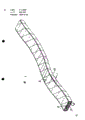
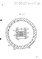
The optical cable of selecting for use shown in Figure 10, contain plastic tube 82, its internal diameter is 83, fiber optic component assembly 40 relaxes and is contained in the internal diameter 83 as shown in Figure 6, assembly 40 therein heart y direction along the path elastic deformation of smooth curved waveform, the waveform bending axis is parallel to each other, and is parallel to the main transverse axis of the flexible thin component 41 of assembly.On the wall of plastic tube 82, embed many separate around fastening element 84, element 84 is being parallel to extending axially of flexible pipe.Each fastening element 84 has the waveform of radially extending, and is suitable for the fastening element of improvement in plastic tube 82 and the mechanical connection of flexible optical cable like this.
Notice, Fig. 1,2,3 to Fig. 5,8 and 9 represented any fiber optic components, or represented fiber optic component assembly can replace optical fiber component 40 by in the loose internal diameter 83 that is contained in optical cable flexible plastic pipe 82 in Fig. 7.
The present invention has very important advantage, namely make optical fiber and/or fibre ribbon, or the flexible thin component of other optical fiber component and fiber optic component can carry out respectively, when requiring the fiber optic component of special construction, can be with desired multifiber and/or fibre ribbon, or other optical fiber component and flexible thin component or many flexible units fit together, and can elastic deformation to form the assembly of the fiber optic component as the front is described.
Claims (9)
1, a kind of fiber optic component subassembly that combines by at least three fiber optic components, every fiber optic component comprises a flexible elongated member, this elongated member has a longilineal xsect, and comprise the first type surface of two basic opposing parallel configurations, one groove that runs through a first type surface total length of these parts is arranged in it, each element has at least one optical fiber that loosely is contained in the described groove, these elements are so made up and are fixed together, so that the first type surface of all elongated members of adjacent elements is on its whole length in the contact of interface, described fiber optic component subassembly is characterised in that:
Described groove in the elongated member of every fiber optic component be by described relatively elongated member be separated to form and keep described or the device of every optical fiber in described groove airtight;
Described fiber optic component subassembly so flexibly is provided with, so that the first type surface of the elongated member of all fiber optic components of this subassembly can advance along the waveform path of smooth curved, the axle of these waveform sweeps (axes of curvature) is parallel to each other and be approximately perpendicular to the center longitudinal axis of described subassembly.
2, fiber optic component subassembly as claimed in claim 1 is characterized in that: the flexible elongated member of described fiber optic component is mutually the same in fact.
3, fiber optic component subassembly as claimed in claim 1 or 2, it is characterized in that: described fiber optic component makes up with form like this and is fixed together, so that except an element, every element serves as the described obturator that is separated to form that is used for fixing each optical fiber in this root optical fiber or the adjacent elements groove.
4, fiber optic component subassembly as claimed in claim 1 or 2, it is characterized in that: the flexible elongated member of each root of some described fiber optic component has at least two grooves on a first type surface of described parts at least, at least loosely holds an optical fiber in each groove.
5, fiber optic component subassembly as claimed in claim 1 is characterized in that: the flexible elongated member of each root of some fiber optic component has at least one groove on its each first type surface at least, loosely holds at least one optical fiber in each described groove.
6, as claim 1 or 5 described fiber optic component subassemblies, it is characterized in that: the described obturator that is separated to form is an elongate cover, and this elongate cover is placed in this groove or a certain groove and is fixed to described elongated member.
7, fiber optic component subassembly as claimed in claim 6, it is characterized in that: described elongate cover, the flange that one or more longitudinal extension is arranged on its surface near the first type surface of described elongated member, it or they wedge effectively in the described groove, to prevent that described elongated member and lid are along the relative motion of their y direction of crosscut.
8, as claim 1, the described fiber optic component subassembly of arbitrary claim in 2,5,7 is characterized in that:
At least one pair of adjacent flexible elongated member has the flange of at least one longitudinal extension, and this flange is carried out wringing fit with the groove along the relevant position longitudinal extension in another of described element.
9, the optical cable that comprises at least one pipe loosely accommodates at least one fiber optic component subassembly in described pipe, it is characterized in that: described at least one fiber optic component subassembly is the described fiber optic component subassembly of above-mentioned arbitrary claim.
Applications Claiming Priority (2)
| Application Number | Priority Date | Filing Date | Title |
|---|---|---|---|
| GB8605016 | 1986-02-28 | ||
| GB868605016A GB8605016D0 (en) | 1986-02-28 | 1986-02-28 | Optical cable |
Publications (2)
| Publication Number | Publication Date |
|---|---|
| CN87102297A CN87102297A (en) | 1987-09-16 |
| CN1016107B true CN1016107B (en) | 1992-04-01 |
Family
ID=10593860
Family Applications (1)
| Application Number | Title | Priority Date | Filing Date |
|---|---|---|---|
| CN87102297A Expired CN1016107B (en) | 1986-02-28 | 1987-02-28 | Optical cable |
Country Status (11)
| Country | Link |
|---|---|
| US (1) | US4846566A (en) |
| EP (1) | EP0236090A3 (en) |
| JP (1) | JPS62215912A (en) |
| KR (1) | KR900006818B1 (en) |
| CN (1) | CN1016107B (en) |
| AU (1) | AU591244B2 (en) |
| CA (1) | CA1277522C (en) |
| GB (2) | GB8605016D0 (en) |
| IN (1) | IN167515B (en) |
| MY (1) | MY101549A (en) |
| NZ (1) | NZ219411A (en) |
Families Citing this family (18)
| Publication number | Priority date | Publication date | Assignee | Title |
|---|---|---|---|---|
| GB8902552D0 (en) * | 1989-02-06 | 1989-03-22 | Telephone Cables Ltd | Optical fibre cable core for submarine use |
| US5039195A (en) * | 1990-05-29 | 1991-08-13 | At&T Bell Laboratories | Composite cable including portions having controlled flexural rigidities |
| FI91333C (en) * | 1990-07-19 | 1994-06-10 | Nokia Kaapeli Oy | Cable |
| US5067830A (en) * | 1990-12-21 | 1991-11-26 | Siecor Corporation | Indented tube for optical ribbon |
| GB2258319B (en) * | 1991-07-30 | 1995-01-18 | Northern Telecom Europ Ltd | Optical fibre cabler comprising optical fibre ribbon |
| US5249249A (en) * | 1991-08-27 | 1993-09-28 | Siecor Corporation | Cable utilizing multiple light waveguide stacks |
| US5323480A (en) * | 1992-11-25 | 1994-06-21 | Raychem Corporation | Fiber optic splice closure |
| US5339378A (en) * | 1993-10-06 | 1994-08-16 | The United States Of America As Represented By The Secretary Of The Navy | Torque-balanced extendable fiber optic cable |
| US5668912A (en) * | 1996-02-07 | 1997-09-16 | Alcatel Na Cable Systems, Inc. | Rectangular optical fiber cable |
| US6097866A (en) * | 1998-05-01 | 2000-08-01 | Alcatel | Optical fiber ribbon |
| DE19838351C2 (en) * | 1998-08-14 | 2000-10-26 | Siemens Ag | Optical cable and cable arrangement |
| US6352374B1 (en) | 2000-06-08 | 2002-03-05 | Amphenol Corporation | Fiber optic connector device |
| US20060140557A1 (en) * | 2001-03-30 | 2006-06-29 | Parris Donald R | Fiber optic cable with strength member formed from a sheet |
| WO2002099227A1 (en) * | 2001-06-05 | 2002-12-12 | Secure Site Environments Llc | Method and apparatus for providing a modular shielded enclosure |
| KR100642382B1 (en) * | 2003-02-26 | 2006-11-03 | 엘에스전선 주식회사 | Optical Cable Having Waved Metal Tube and Method and Apparatus for Producing the Same |
| US20090317039A1 (en) * | 2008-06-19 | 2009-12-24 | Blazer Bradley J | Fiber optic cable having armor with easy access features |
| US7802924B2 (en) * | 2008-09-29 | 2010-09-28 | Infinera Corporation | Fiber optic ferrule |
| EP3705924B1 (en) * | 2017-11-02 | 2022-10-19 | Sumitomo Electric Industries, Ltd. | Optical fiber unit and optical fiber cable |
Family Cites Families (20)
| Publication number | Priority date | Publication date | Assignee | Title |
|---|---|---|---|---|
| DK138564B (en) * | 1976-11-09 | 1978-09-25 | Nordiske Kabel Traad | Method of manufacturing a light-conducting element for placement in a tubular casing. |
| DE2817045A1 (en) * | 1977-04-22 | 1978-11-02 | Bicc Ltd | OPTICAL CABLE |
| CA1112310A (en) * | 1977-05-13 | 1981-11-10 | Peter Fearns | Overhead electric transmission systems |
| FR2397645A1 (en) * | 1977-07-12 | 1979-02-09 | Thomson Brandt | BED OF OPTICAL FIBERS IN AN OPTICAL TRANSMISSION CABLE, METHOD FOR MANUFACTURING THE SAID BED AND OPTICAL CABLE CONTAINING A MULTIPLICITY OF SUCH BODIES |
| US4230898A (en) * | 1977-10-19 | 1980-10-28 | Emmel Leroy L | Elongated filament lattice structure |
| FR2432721A1 (en) * | 1978-07-31 | 1980-02-29 | Silec Liaisons Elec | WIRING ELEMENT FOR OPTICAL FIBERS |
| JPS5529807A (en) * | 1978-08-23 | 1980-03-03 | Kokusai Denshin Denwa Co Ltd <Kdd> | Optical fiber submaring cable |
| GB1601004A (en) * | 1978-09-26 | 1981-10-21 | Bicc Ltd | Optical cable |
| DE2902259C2 (en) * | 1979-01-22 | 1987-04-23 | AEG KABEL AG, 4050 Mönchengladbach | Band-shaped light guide element |
| DE3108109A1 (en) * | 1981-03-04 | 1982-09-23 | Philips Kommunikations Industrie AG, 8500 Nürnberg | Protective element for optical fibres having a temperature-compensated profiled body |
| JPS5931906A (en) * | 1982-08-17 | 1984-02-21 | Nippon Telegr & Teleph Corp <Ntt> | Multicore optical fiber cable |
| GB8316494D0 (en) * | 1983-06-17 | 1983-07-20 | Bicc Plc | Flexible elongate body |
| ZA844474B (en) * | 1983-06-17 | 1985-02-27 | Bicc Plc | Optical fibre ribbon structure |
| DE3339389A1 (en) * | 1983-10-29 | 1985-05-09 | Standard Elektrik Lorenz Ag, 7000 Stuttgart | OPTICAL NEWS CABLE |
| GB8406635D0 (en) * | 1984-03-14 | 1984-04-18 | Bicc Plc | Optical fibre element |
| FR2562272B1 (en) * | 1984-03-30 | 1987-09-25 | Cables Electro Telecommunicati | IMPROVEMENT IN OPTICAL CABLES WITH FREE STRUCTURE |
| GB8412276D0 (en) * | 1984-05-14 | 1984-06-20 | Telephone Cables Ltd | Manufacture of optical fibre cable |
| GB8416000D0 (en) * | 1984-06-22 | 1984-07-25 | Bicc Plc | Optical fibre ribbon structure |
| GB8415999D0 (en) * | 1984-06-22 | 1984-07-25 | Bicc Plc | Optical fibre element |
| GB8501450D0 (en) * | 1985-01-21 | 1985-02-20 | Bicc Plc | Optical cable manufacture |
-
1986
- 1986-02-28 GB GB868605016A patent/GB8605016D0/en active Pending
-
1987
- 1987-02-24 CA CA000530426A patent/CA1277522C/en not_active Expired - Lifetime
- 1987-02-25 NZ NZ219411A patent/NZ219411A/en unknown
- 1987-02-26 IN IN172/DEL/87A patent/IN167515B/en unknown
- 1987-02-26 US US07/019,011 patent/US4846566A/en not_active Expired - Fee Related
- 1987-02-27 EP EP87301751A patent/EP0236090A3/en not_active Withdrawn
- 1987-02-27 AU AU69559/87A patent/AU591244B2/en not_active Ceased
- 1987-02-27 GB GB8704705A patent/GB2187306B/en not_active Expired
- 1987-02-28 KR KR1019870001756A patent/KR900006818B1/en not_active IP Right Cessation
- 1987-02-28 CN CN87102297A patent/CN1016107B/en not_active Expired
- 1987-02-28 JP JP62044148A patent/JPS62215912A/en active Pending
- 1987-02-28 MY MYPI87000209A patent/MY101549A/en unknown
Also Published As
| Publication number | Publication date |
|---|---|
| GB8704705D0 (en) | 1987-04-01 |
| CN87102297A (en) | 1987-09-16 |
| GB2187306B (en) | 1989-04-26 |
| MY101549A (en) | 1991-12-17 |
| GB8605016D0 (en) | 1986-04-09 |
| AU591244B2 (en) | 1989-11-30 |
| KR870008198A (en) | 1987-09-25 |
| GB2187306A (en) | 1987-09-03 |
| NZ219411A (en) | 1989-05-29 |
| KR900006818B1 (en) | 1990-09-21 |
| CA1277522C (en) | 1990-12-11 |
| EP0236090A2 (en) | 1987-09-09 |
| EP0236090A3 (en) | 1989-04-26 |
| AU6955987A (en) | 1987-09-03 |
| IN167515B (en) | 1990-11-10 |
| US4846566A (en) | 1989-07-11 |
| JPS62215912A (en) | 1987-09-22 |
Similar Documents
| Publication | Publication Date | Title |
|---|---|---|
| CN1016107B (en) | Optical cable | |
| US10031302B2 (en) | Optical fiber cable with elongate strength member recessed in armor layer | |
| US6249629B1 (en) | Robust fiber optic cables | |
| US6807347B2 (en) | High density fiber optic cable | |
| US4188088A (en) | Optical element for use in optical transmission means | |
| GB2094020A (en) | A method of manufacturing an optical fibre cable | |
| AU707427B2 (en) | Optical fibre cable | |
| KR940000839B1 (en) | Optical fiber unit | |
| JP2000075177A (en) | Fiber optic ribbon connecting cable | |
| US4793685A (en) | Optical cable with nonmetallic reinforcing elements | |
| US5269128A (en) | Wire ropes with cores having elliptically curved grooves thereon | |
| KR100511116B1 (en) | Loose tube optical cable having straight aggregation structure | |
| KR100526506B1 (en) | Optical cable for air blow installation | |
| DE2556861A1 (en) | FLEXIBLE, HEAVY DUTY LIGHT GUIDE CABLE | |
| CN1011087B (en) | Optical fiber unit | |
| GB2215084A (en) | Optical fibre ribbon containing cables | |
| CN1124354A (en) | An optical fiber cable and an associated method of manufacture | |
| EP0394618B1 (en) | Optical cable | |
| EP0414786A1 (en) | Cores for wire ropes. | |
| EP1018662B1 (en) | Optical cable | |
| US11994729B2 (en) | Optical fiber cable with parallel ribbon subunits | |
| NZ228597A (en) | Extruding reinforced tube for optical cable | |
| CN1259677A (en) | Optical fiber bundle, and optical cable made up of by using same | |
| CN1163766C (en) | Optical fiber cable | |
| US20230296855A1 (en) | High density, low diameter cable with rollable fiber optic ribbon |
Legal Events
| Date | Code | Title | Description |
|---|---|---|---|
| C06 | Publication | ||
| PB01 | Publication | ||
| C10 | Entry into substantive examination | ||
| SE01 | Entry into force of request for substantive examination | ||
| C13 | Decision | ||
| GR02 | Examined patent application | ||
| C14 | Grant of patent or utility model | ||
| GR01 | Patent grant | ||
| C19 | Lapse of patent right due to non-payment of the annual fee | ||
| CF01 | Termination of patent right due to non-payment of annual fee |