The application comprises and relates to the theme that is that on March 28th, 2008 disclosed in the japanese priority patent application JP 2008-088238 that Japan Patent office submits to, incorporates its full content into this paper as a reference.
Embodiment
Below, with the preferred implementation that invention will be described in detail with reference to the attached drawing.
Fig. 1 shows the cutaway view according to the negative pole of embodiment of the present invention.Negative pole for example is used for the electrochemical appliance like secondary cell, and comprises the negative electrode collector 1 with a pair of surface and be arranged on the negative electrode active material layer 2 on the negative electrode collector 1.
Negative electrode collector 1 is preferred by the material with good electrochemical stability, conductivity and mechanical strength, more particularly comprises one or more and does not process as the material that constitutes element with the metallic element of electrode reaction thing formation intermetallic compound.The instance of such metal material comprises copper (Cu), nickel (Ni), titanium (Ti), iron (Fe), chromium (Cr), stainless steel etc.
Above-mentioned material preferably includes one or more and negative electrode active material layer 2 alloyed metal (AM) elements as constituting element; Because can improve the adherence between negative electrode collector 1 and the negative electrode active material layer 2, make that negative electrode active material layer 2 is not easy to peel off from negative electrode collector 1.Comprise under the situation of silicon as negative electrode active material at negative electrode active material layer 2, do not form intermetallic compound, but comprise copper, nickel, iron etc. with the instance of negative electrode active material layer 2 alloyed metal (AM) elements with the electrode reaction thing.According to intensity and conductivity, these metallic elements are preferred.
Negative electrode collector 1 can have monolayer constructions will or multi-ply construction.Have at negative electrode collector 1 under the situation of multi-ply construction; For example; Preferably with the contiguous layer of negative electrode active material layer 2 by can processing with negative electrode active material layer 2 alloyed metal (AM) materials, and do not process by any other metal material with negative electrode active material layer 2 contiguous layers.
The surface of negative electrode collector 1 is preferably by roughening, owing to can improve the adherence between negative electrode collector 1 and the negative electrode active material layer 2 through so-called anchoring effect.In this case, at least can with negative electrode collector 1 with negative electrode active material layer 2 facing surfaces roughenings.As the roughening method, for example, can use and form fine grain method etc. through electrolytic treatments.Electrolytic treatments is that a kind of electrolysis of in electrolysis tank, passing through forms fine particle to form the method for rough surface on the surface of negative electrode collector 1.The Copper Foil that is formed by electrolytic treatments is commonly referred to " electrolytic copper foil ".
Negative electrode active material layer 2 comprises a plurality of anode active material particles, and if be necessary that negative electrode active material layer 2 can comprise any other material such as cathode conductive agent.Anode active material particles comprises that one or more can embed and take off the negative material of embedding electrode reaction thing (for example lithium etc.).
The instance that can embed and take off the negative material of embedding electrode reaction thing comprises and can embed and take off embedding electrode reaction thing and comprise that at least a conduct that is selected from the group of being made up of metallic element and metalloid element constitutes the material of element, because can obtain high-energy-density.Such material can be any in simple substance, alloy and the compound of metallic element and metalloid element; Can comprise maybe that at least part comprises one or more the phase that is selected from them.In the present invention, alloy is meant the alloy that comprises two or more metallic elements and comprises one or more metallic elements and the alloy of one or more metalloid elements.And alloy can comprise nonmetalloid.The structure of alloy is solid solution, eutectic (eutectic mixture), intermetallic compound or the structure that is selected from the two or more coexistences in them.
The instance of above-mentioned metallic element and above-mentioned metalloid element comprises the metallic element and the metalloid element that can form alloy with the electrode reaction thing.Instantiation comprises magnesium (Mg), boron (B), aluminium (Al), gallium (Ga), indium (In), silicon, germanium (Ge), tin (Sn), plumbous (Pb), bismuth (Bi), cadmium (Cd), silver (Ag), zinc (Zn), hafnium (Hf), zirconium (Zr), yttrium (Y), palladium (Pd), platinum (Pt) etc.Among them, it is preferred being selected from least a in the group of being made up of silicon and tin, and silicon is preferred, because the ability that silicon has high embedding and takes off embedding electrode reaction thing, thereby can obtain high-energy-density.
Comprise that silicon comprises simple substance, alloy and the compound of silicon as the instance of the material that constitutes element, and part comprises one or more the material of phase that is selected from them at least.
The instance of the alloy of silicon comprises the alloy that comprises the second formation element of at least a conduct except silicon that is selected from the group of being made up of tin, nickel, copper, iron, cobalt (Co), manganese (Mn), zinc, indium, silver, titanium, germanium, bismuth, antimony (Sb) and chromium.The examples for compounds of silicon comprises the compound that comprises oxygen (O) or carbon (C), and compound can comprise the above-mentioned second formation element except silicon.The alloy of silicon and the examples for compounds of silicon comprise SiB
4, SiB
6, Mg
2Si, Ni
2Si, TiSi
2, MoSi
2, CoSi
2, NiSi
2, CaSi
2, CrSi
2, Cu
5Si, FeSi
2, MnSi
2, NbSi
2, TaSi
2, VSi
2, WSi
2, ZnSi
2, SiC, Si
3N
4, Si
2N
2O, SiO
v(0<v≤2), SnO
w(0<w≤2), LiSiO etc.
Negative electrode active material layer 2 is through for example vapor phase method, liquid phase method, sintering process, spray-on process or be selected from the combination of the two or more methods in them, does not promptly need the method for negative pole binding agent and forms.As vapor phase method, for example, can use physical deposition method or chemical deposition, more particularly, vacuum vapor deposition method, sputtering method, ion plating method, laser ablation method, thermal chemical vapor deposition (CVD) method, pecvd etc.As liquid phase method, can use known technology as electroplating or electroless plating.Sintering process is for example a kind of such method, granular negative electrode active material and binding agent etc. is mixed forming mixture, and this mixture is dispersed in the solvent, and coating, then this mixture of heating under the temperature of the fusing point that is higher than binding agent etc.As sintering process, can use known technology, and for example can use, air sintering method, reaction sintering method or hot pressing sintering method.
Under the situation that negative electrode active material layer 2 forms through sedimentation such as vapor phase method, negative electrode active material layer 2 can have through implementing the monolayer constructions will that deposition step forms for 1 time, perhaps through repeating the multi-ply construction that this deposition step repeatedly forms.Yet; Using under the situation of the vacuum evaporation method in deposition process, follow high temperature etc.; In order to prevent the fire damage of anticathode collector body 1, negative electrode active material layer 2 preferably has multi-ply construction, because when implementing deposition step respectively repeatedly the time; Compare with the situation of only implementing deposition step 1 time, the duration that negative electrode collector 1 is exposed to high temperature reduces.
Negative electrode active material layer 2 preferred and negative electrode collector 1 alloyings; Because negative electrode collector 1 and negative electrode active material layer 2 are by linking into an integrated entity securely; Thereby can improve the electronic conductivity between them, and can prevent the swelling and the contraction of negative electrode active material layer 2 in electrode process.In this case; Negative electrode collector 1 can be in their whole zones located adjacent one another with negative electrode active material layer 2; Perhaps alloying each other in the part in this zone; Because when negative electrode collector 1 and negative electrode active material layer 2 at least in the part in this zone each other during alloying, with they each other not the situation of alloying compare, can improve the adherence between negative electrode collector 1 and the negative electrode active material layer 2.In addition, " alloying " is meant not only that the formation element of formation element and the negative electrode active material layer 2 of negative electrode collector 1 forms the state of complete alloy but also is meant and constitutes Elements Diffusion among each other and the state that mixes.In this case; In the interface between them; The formation element of negative electrode collector 1 can be spread in the negative electrode active material layer 2, and perhaps the formation element of negative electrode active material layer 2 can be spread in the negative electrode collector 1, among perhaps they can be spread to each other.
And negative electrode active material layer 2 is preferably included in a plurality of layers that have different oxygen on the thickness direction, because can prevent the swelling and the contraction of negative electrode active material layer 2 in electrode process.In this case, negative electrode active material layer 2 preferably includes a plurality of layers of two types with different oxygen, and more preferably, two types layer alternatively laminated is because can obtain higher effect.In having two types layer of different oxygen, oxygen content can obviously differ from one another, and perhaps can not obviously differ from one another.In the latter case, preferably continuously change oxygen content.Yet the oxygen content in the preferred two types layer is not to differ from one another to a great extent, because oxygen content is significantly changed, ions diffusion possibly reduce or resistance possibly increase.
The instance of cathode conductive agent comprises material with carbon element such as graphite, carbon black, acetylene black and Ketjen black (ketjen black).Can use only one or more the mixture that is selected from them.As long as cathode conductive agent is the material with conductivity, just can use any metal material or any conducting polymer.
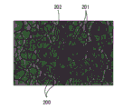
With reference to Fig. 2 A and Fig. 2 B, the concrete structure of negative pole will be described below.Fig. 2 A and Fig. 2 B show surface structure, and Fig. 2 A is SEM image (secondary electron image), and Fig. 2 B is the SEM treatment of picture image shown in Fig. 2 A.Fig. 2 A and Fig. 2 B show negative electrode active material and have multi-ply construction, and negative electrode active material layer 2 is through the situation of vapor phase method (vacuum deposition method) formation.
When passing through the multiplication factor of SEM with 2000 times; When the laminating direction of negative electrode collector 1 and negative electrode active material layer 2 is observed negative pole (negative electrode active material layer 2) surperficial; Shown in Fig. 2 A, a plurality of anode active material particles 200 have been observed with variable grain diameter.In this case; Exist an anode active material particles 200 and other anode active material particles 200 obviously to separate the also part of individualism, and a plurality of anode active material particles 200 (primary particle 201) is assembled for seeming the part of a particle (second particle 202).
When through on the SEM image shown in Fig. 2 A, carrying out image processing when confirming the border between the anode active material particles 200, shown in Fig. 2 B, clearly obtained the profile of each anode active material particles 200.Thereby the existence zone (extent of occupation) of each anode active material particles 200 make that the number of anode active material particles 200 is isarithmic, and the particle area of each anode active material particles 200 is computable by accurately identification.
From the average grain area of a plurality of anode active material particles 200 of the surface observation of negative pole (negative electrode active material layer 2) at 1 μ m
2~60 μ m
2Scope in.Correctly adjust the particle diameter distribution of a plurality of anode active material particles 200, make that the swelling of in electrode process, following negative electrode active material layer 2 and the internal stress of contraction are disperseed, and the shape stability of whole negative pole is held.Thereby, be used at this negative pole under the situation of secondary cell, can obtain excellent cycle characteristics.Calculate above-mentioned average grain area based on the image (hereinafter, abbreviating " image of processing " as) that carries out image processing on shown in Fig. 2 B its by a plurality of anode active material particles 200 that are included in the predetermined viewing area (42 μ m are long, and 64 μ m are wide).
More particularly, when the average grain area less than 1 μ m
2The time, the total surface area of anode active material particles 200 increases.Thereby; Be used under the situation of electrochemical appliance with electrolyte at negative pole; Anode active material particles 200 and electrolyte reaction; Thereby be easy to form irreversible reaction coating such as SEI (solid electrolyte interface), make the electrical property (for example, the battery capacity in the secondary cell) of electrochemical appliance to reduce.On the other hand, when the average grain area greater than 60 μ m
2The time, the area that contacts with electrolyte reduces, and make that the turnover of electrode reaction thing possibly be uneven in anode active material particles 200, and negative electrode active material layer 2 possibly break or landing.
The average grain area is preferably at 2 μ m
2~40 μ m
2Scope in, and more preferably at 5 μ m
2~17 μ m
2Scope in because the possibility that the performance of above-mentioned electrochemical appliance reduces is further reduced, make to obtain higher effect.
In said a plurality of anode active material particles 200; Exist its entire image (whole profile of an anode active material particles 200) be not included in the above-mentioned viewing area with and only a part be included in the situation of the anode active material particles in the above-mentioned viewing area, when the count particles area, do not comprise these anode active material particles.
Especially, have 20 μ m
2~30 μ m
2The ratio (area ratio) of summation of particle area of summation and a plurality of anode active material particles 200 of particle area of anode active material particles 200 of particle area preferably in 10%~60% scope; Because can correctly be adjusted in a plurality of anode active material particles 200, have 20 μ m
2~30 μ m
2The occupation ratio of anode active material particles 200 (helping to obtain the above-mentioned shape stability of whole negative pole) of particle area, and the balance between the occupation ratio of other anode active material particles makes to obtain higher effect.Area ratio is by area ratio (%)=(have 20 μ m
2~30 μ m
2The summation of particle area of summation/a plurality of anode active material particles 200 of particle area of anode active material particles 200 of particle area) * 100 expressions.Area ratio is and the same image and the value calculated based on the processing in the predetermined viewing area in the situation of above-mentioned average grain area.
And the average circularity of a plurality of anode active material particles 200 is preferably more than 0.4, and more preferably in 0.4~0.8 scope.When average circularity less than 0.4 the time, the profile of each anode active material particles 200 departs from perfect circular, makes that negative electrode active material layer 2 is difficult to smooth swelling and contractions in electrode process.Average circularity is and the same image and the value (supposing that perfect circle is 1.0) calculated based on the processing in the viewing area of being scheduled in the situation of above-mentioned average grain area.Multiplication factor reduces to tend to bigger value to average circularity along with observing down at SEM, therefore, as stated, the value calculated for SEM image of the average circularity of regulation here based on 2000 times multiplication factor observation.
In order to carry out above-mentioned image processing, can use any software (image processing software).As image processing software, for example, can use to have the software that automatically performs the function of above-mentioned image processing based on the SEM image.When using the such type that automatically performs image processing software, do not comprise artificial error etc., the feasible image that can obtain the processing of homogeneous and reproducibility excellence.Particularly, as image processing software, the software with function (function that comprises the count particles area) of calculating the average grain area is preferred, because the average grain area can high precision computation.In this case; Except having the function of calculating the average grain area; This software also preferably has the area ratio of calculating and the function of average circularity; Because can be with high precision computation average grain area, area ratio and average circularity (abbreviating hereinafter, " average grain area etc. " as) through a kind of image processing software of use.
When carrying out image processing, under the situation about can not discern through the processing of image processing software on the border between the anode active material particles 200, can the manual identification border.More particularly; But although in the SEM image, there is the border of visual identity; But this border also is not included under the situation about handling in the image; Can be to handling processing (treatment for correcting) that image adds (writing) border so that this border is incorporated in the image of processing, because after carrying out such treatment for correcting, can be with higher accuracy computation average grain area etc.
And; Obviously be present in the SEM image at foreign substance (like dust); And exist foreign substance to influence under the situation of possibility of precision etc. of image processing; From the image of handling, removing the processing (treatment for correcting) of foreign substance can manually carry out, because after carrying out such treatment for correcting, can improve the precision that is used to calculate average grain area etc.
In addition; When calculating average grain area etc. in the predetermined viewing area (42 μ m are long, and 64 μ m are wide), possibly depend under the situation of the position of confirming as viewing area in the error of observed average grain area etc.; Preferably calculate the average grain area in a plurality of viewing areas through changing the visual field; Obtain the mean value of each calculated value then, because after carrying out such average treatment, can be with high precision computation average grain area etc.The number of times that changes the visual field can be set arbitrarily.
In Fig. 2 A and Fig. 2 B, the situation of vapor phase method as the instance of the method that forms negative electrode active material layer 2 of using described; Yet,, can observe a plurality of anode active material particles through using SEM even under the situation of any other formation method of use such as liquid phase method, sintering process or spray-on process.Therefore, even under the situation of other formation methods of use, through also calculating average grain area etc. with identical step in reference to the situation of Fig. 2 A and Fig. 2 B description.
Make negative pole through for example following steps.
Fig. 3 shows the schematic configuration instance of the manufacturing installation (vaporising device) that is used to make negative pole.This vaporising device forms negative electrode active material layer 2 on the surface of negative electrode collector 1 through for example electron-beam vapor deposition method.
More particularly, this vaporising device is included in evaporation source 102A and 102B ( crucible 121A and 121B and evaporated material 122A and 122B), jar shape roller (can roll) (film forming roller) 103A and 103B, shutter (shutter) 104A and 104B, take up roll 105 and 106, guide roller 107~111 and the feed roller 112 in the evaporator tank 101.Vacuum pumping hardware 113 is arranged on the outside of evaporator tank 101.
Evaporator tank 101 is divided into evaporation source chamber 101A and 101B and evaporation object transfer chamber 101C through the demarcation strip 114 with two opening 114K. Evaporation source chamber 101A and 101B opened through wall in 115 minutes.The entering evaporation source chamber 101A of the outer surface of jar shape roller 103A and 103B and part 120A and the 120B of 101B are the zones that deposits evaporated material 122A and 122B respectively.
Evaporation source 102A and 102B comprise for example electron gun (not shown), and will be heated to evaporation (gasification) as the evaporated material 122A and the 122B of negative material.For example, add cooling system can for crucible 121A and 121B like water jacket.
Negative electrode collector 1 as the evaporation target has and for example is with shape to construct continuously.In negative electrode collector 1, for example, through take up roll 105 coilings one end, and through the take up roll 106 coiling other ends.Thereby; Negative electrode collector 1 is transferred to take up roll 106 with this order from take up roll 105 through guide roller 107, jar shape roller 103A, guide roller 108, feed roller 112, guide roller 109 and 110, jar shape roller 103B and guide roller 111, and negative electrode collector 1 is reeled through take up roll 106 then.
When making negative pole through this vaporising device, when transmission negative electrode collector 1, the evaporated material 122A and the 122B that are contained among crucible 121A and the 121B are evaporated with on the surface that is deposited on negative electrode collector 1, thereby have formed negative electrode active material layer 2.In this case; In the step of transmission negative electrode collector 1; Evaporated material 122A by crucible 121A evaporation is deposited on the surface (front) of negative electrode collector 1, and is deposited on another surface (back side) of negative electrode collector 1 by the evaporated material 122B of crucible 121B evaporation.Thereby, the step through implementing transmission only once, negative electrode active material layer 2 just can be formed on two surfaces of negative electrode collector 1.
Under the situation that forms negative electrode active material layer 2; Negative electrode collector 1 can only transmit in one direction; Make negative electrode active material layer 2 have monolayer constructions will, perhaps negative electrode collector 1 can two-way reciprocating motion, makes negative electrode active material layer 2 have multi-ply construction.In this case, can adjust condition arbitrarily such as the transmission speed of negative electrode collector 1 and the formation speed of negative electrode active material layer 2 (deposition velocity of evaporated material 122A and 122B).
In this is described, used the vaporising device that comprises two evaporation source chamber 101A and 101B; Yet vaporising device is not limited to this, and can use the vaporising device that comprises an evaporation source chamber.
Making under the situation of negative pole, through the adjustment average grain area that can change above-mentioned a plurality of anode active material particles etc. of creating conditions.
The instance that is used to form the condition of the negative electrode active material layer 2 with monolayer constructions will comprises the surface roughness of negative electrode collector 1 (for example, 10 mean roughness R), the deposition velocity of negative material etc.In addition, if be necessary, in the process of deposition negative material, can introduce gas (for example, argon (Ar) gas etc.), and can adjust the amount of introducing.
Be used to form the instance of the condition of negative electrode active material layer 2 with multi-ply construction through the device that can transmit negative electrode collector 1 as shown in Figure 3; The condition of under the situation of the negative electrode active material layer 2 that has monolayer constructions will in formation, describing, also comprise the transmission speed of negative electrode collector 1, the number of plies of negative electrode active material layer 2 etc.
According to negative pole, from the average grain area of a plurality of anode active material particles of the surface observation of negative electrode active material layer 2 at 1 μ m
2~60 μ m
2Scope in, make that the internal stress of the swelling of in electrode process, following negative electrode active material layer 2 is disperseed, thereby keep the shape stability of whole negative pole.Therefore, when electrochemical appliance used this negative pole, this negative pole can help the improvement of electrochemical appliance performance.More particularly, be used at this negative pole under the situation of secondary cell, this negative pole can help the improvement of cycle characteristics.In this case, when the average grain area of a plurality of anode active material particles at 2 μ m
2~40 μ m
2Scope in, more particularly at 5 μ m
2~17 μ m
2Scope in the time, can obtain higher effect.
And, have 20 μ m
2~30 μ m
2The ratio (area ratio) of summation of particle area of summation and a plurality of anode active material particles 200 of particle area of anode active material particles 200 of particle area in 10%~60% scope the time; When perhaps the average circularity of a plurality of anode active material particles is in 0.4~0.8 scope in viewing area, can obtain higher effect.
In addition, comprise when being selected from least a in the group of forming by simple substance, alloy and the compound of silicon negative electrode active material layer 2 easy swelling and contractions in electrode process when anode active material particles.Therefore, can reduce the swelling of following negative electrode active material layer 2 and the internal stress of contraction effectively, make to obtain higher effect.
The application example of above-mentioned negative pole then, will be described below.An instance as electrochemical appliance used secondary cell, and negative pole is used for secondary cell as follows.
First kind of secondary cell
Fig. 4 and Fig. 5 show the cutaway view of first kind of secondary cell, and Fig. 5 shows the enlarged drawing of the part of spiral winding electrode shown in Figure 4 20.Secondary cell described herein is a lithium rechargeable battery, and wherein the capacity of negative pole 22 is based on as the embedding of the lithium of electrode reaction thing with take off embedding and represent.
First kind of secondary cell mainly holds spiral winding electrode 20 and a pair of insulation board 12 and 13 that comprise with the positive pole 21 and the negative pole 22 of 23 screw windings of the barrier film between them in the battery case 11 of hollow cylindrical basically.Use the battery structure of columniform battery case 11 to be called column type.
Battery case 11 has hollow structure, a wherein end of battery case 11 sealing, and its other end opens wide, and battery case 11 is processed by metal material such as iron, aluminium, their alloy or stainless steel.Under the situation that battery case 11 is fabricated from iron, for example, battery case 11 can be coated with like nickel etc.Between arranging that a pair of insulation board 12 and 13 makes that spiral winding electrode 20 is clipped in, and a pair of insulation board 12 and 13 extends along the direction perpendicular to coiling face on every side.
At the openend of battery case 11, through with packing ring 17 caulkeds battery cover 14 being installed and being arranged in relief valve mechanism 15 and the ptc device (PTC device) 16 in the battery cover 14.Thereby the inside of battery case 11 is sealed.Battery cover 14 is by for example processing with battery case 11 identical metal materials.Relief valve mechanism 15 is electrically connected to battery cover 14 through PTC device 16.In relief valve mechanism 15, when internal pressure in the battery being increased to a certain degree or when higher, discoid plate 15A upsprings so that cut off being electrically connected between battery cover 14 and the spiral winding electrode 20.When temperature raise, PTC device 16 limited electric current through increasing resistance, with the unusual heat generation that prevents to be risen by high-current leading.Packing ring 17 is processed by for example insulating material, and bitumen coated is used on its surface.
Centrepin 24 can insert the center of spiral winding electrode 20.In spiral winding electrode 20, will be connected to positive pole 21 by the positive wire of processing such as the metal material of aluminium 25, and will be connected to negative pole 22 by the negative wire of processing such as the metal material of nickel 26.Positive wire 25 is electrically connected to battery cover 14 through this positive wire 25 is connected to relief valve mechanism 15 through modes such as welding, and negative wire 26 is electrically connected to battery case 11 through this negative wire 26 is connected to battery case 11 through modes such as welding.
Anodal 21 through forming on two faces that positive electrode active material layer 21B are arranged in the positive electrode collector 21A with an opposite.Positive electrode active material layer 21B can be formed on only face of positive electrode collector 21A.
Positive electrode collector 21A is processed by for example metal material such as aluminium, nickel or stainless steel.
Positive electrode active material layer 21B comprises as one or more of positive active material can embed the positive electrode with removal lithium embedded, and if be necessary that positive electrode active material layer 21B can comprise any other material such as anodal binding agent or anodal conductive agent.
As the positive electrode that can embed with removal lithium embedded, for example, lithium-containing compound is preferred, because can obtain high-energy-density.The instance of lithium-containing compound comprises the composite oxides that contain lithium and transition metal, or contains the phosphate compounds of lithium and transition metal.Among them, it is preferred comprising at least a lithium-containing compound as transition metal that is selected from the group of being made up of cobalt, nickel, manganese and iron, because can obtain higher voltage.Composite oxides or phosphate compounds are by for example Li
xM1O
2Or Li
yM2PO
4Expression.In this chemical formula, M1 and M2 represent one or more transition metals separately.The value of x and y depends on the charging-discharge condition of battery, and usually respectively in the scope of 0.05≤x≤1.10 and 0.05≤y≤1.10.
The instance that contains the composite oxides of lithium and transition metal comprises lithium cobalt composite oxide (Li
xCoO
2), lithium nickel composite oxide (Li
xNiO
2), lithium/nickel/cobalt composite oxide (Li
xNi
1-zCo
zO
2(z<1)), lithium nickel cobalt manganese composite oxides (Li
xNi
(1-v-w)Co
vMn
wO
2) (v+w<1)), have the complex Li-Mn-oxide (LiMn of spinel structure
2O
4) etc.Among them, the composite oxides that comprise cobalt are preferred, because can obtain high power capacity, and can obtain excellent cycle characteristics.The instance that contains the phosphate compounds of lithium and transition metal comprises lithium iron phosphate compound (LiFePO
4), ithium iron manganese phosphate compounds (LiFe
1-uMn
uPO
4(u<1)) etc.
Except above-mentioned material, the instance that can embed with the positive electrode of removal lithium embedded comprises oxide such as titanium oxide, vanadium oxide or manganese dioxide; Disulphide such as titanium disulfide or molybdenum sulfide; Chalcogenide such as selenizing niobium; Sulphur; And conducting polymer such as polyaniline or polythiophene.
The positive electrode that can embed with removal lithium embedded can be any material except above-mentioned material.Can use the two or more mixture that is selected from arbitrarily in the above-mentioned positive electrode.
The instance of anodal binding agent comprises synthetic rubber, like butylbenzene base rubber, fluorine-based rubber or ethylene propylene diene rubber; And macromolecular material, like Kynoar.Can use only one or more the mixture that is selected from them.
The instance of anodal conductive agent comprises and above-mentioned cathode conductive agent identical materials.
Negative pole 22 has and above-mentioned negative pole identical construction, and through forming on two faces that negative electrode active material layer 22B are arranged in the negative electrode collector 22A with an opposite.The structure of negative electrode collector 22A and the negative electrode active material layer 22B structure with negative electrode collector 1 and negative electrode active material layer 2 respectively is identical.In negative pole 22, the charging capacity that can embed in the negative material with removal lithium embedded is preferably greater than anodal discharge capacity.
Fig. 6 shows the planar configuration of positive pole shown in Figure 5 21 and negative pole 22.In Fig. 6, in anodal 21, form the area shadingization of positive electrode active material layer 21B, the zone that in negative pole 22, forms negative electrode active material layer 22B is shadowed also.
In this secondary cell, for example, when positive electrode active material layer 21B was arranged in the part (for example, middle section in the longitudinal direction) on the surface of positive electrode collector 21A, negative electrode active material layer 22B was arranged on the whole surface of negative electrode collector 22A.In other words, negative electrode active material layer 22B be arranged on the negative electrode collector 22A with positive electrode active material layer 21B region facing R1 in and not with positive electrode active material layer 21B region facing R2 in.
In this case, the part that only is arranged in the region R 1 of negative electrode active material layer 22B helps charging-exoelectrical reaction, and the part that is arranged in the region R 2 of negative electrode active material layer 22B is helpless to charging-exoelectrical reaction.Thereby; In the part that is arranged in region R 2; The state of negative electrode active material layer 22B (such as the particle diameter distribution of a plurality of anode active material particles) does not change through charging-exoelectrical reaction, makes that the state (initial condition) after making negative pole 22 is held and not change.Therefore; Under the situation of the average grain area that calculates above-mentioned a plurality of anode active material particles etc.; Preferred calculating is arranged in the average grain area among the negative electrode active material layer 22B in the region R 2 etc.; Because can calculate average grain area etc. with reproducibility well, and irrelevant with the history of charging and discharge.
Barrier film 23 at a distance from anodal 21 with negative pole 22 between, let lithium ion pass through, prevent simultaneously owing to the short circuit current that causes that contacts between positive pole 21 and the negative pole 22.Barrier film 23 is processed by the perforated membrane of for example synthetic resin (like polytetrafluoroethylene, polypropylene or polyethylene), the perforated membrane of pottery etc., and barrier film 23 can have the wherein range upon range of structure that two or more perforated membranes are arranged.
Barrier film 23 is impregnated with electrolyte.Barrier film 23 can play as the main effect of barrier film and as electrolytical effect (that is, barrier film 23 can comprise ionic conductivity but not comprise electronic conductivity).
The solvent that is included in the electrolyte comprises, for example, one or more nonaqueous solventss such as organic solvent, and the instantiation of nonaqueous solvents comprises following solvent.Can combination in any below with the solvent of describing.
Examples of non-aqueous comprises ethylene carbonate, propylene carbonate, butylene carbonate, dimethyl carbonate, diethyl carbonate, methyl ethyl carbonate, carbonic acid first propyl ester, gamma-butyrolacton, gamma-valerolactone, 1; 2-dimethoxy-ethane, oxolane, 2-methyltetrahydrofuran, oxinane, 1; 3-dioxolanes, 4-methyl isophthalic acid; 3-dioxolanes, 1; 3-diox, 1; 4-diox, methyl acetate, ethyl acetate, methyl propionate, ethyl propionate, methyl butyrate, methyl isobutyrate, methyl trimethylacetate, tri-methyl ethyl acetate, acetonitrile, glutaronitrile, adiponitrile, methoxyacetonitrile, 3-methoxypropionitrile, N; Dinethylformamide, N-methyl pyrrolidone, N-methyl oxazolidinone, N, N '-methylimidazole alkane ketone, nitromethane, nitroethane, sulfolane, trimethyl phosphate, methyl-sulfoxide etc. are because can obtain excellent battery capacity, excellent cycle characteristics, excellent preservation characteristics etc.Among them, it is preferred being selected from least a in the group of being made up of ethylene carbonate, propylene carbonate, gamma-butyrolacton, dimethyl carbonate, diethyl carbonate and methyl ethyl carbonate.In this case; Solvent (for example preferably includes high viscosity (high-k) solvent; Relative dielectric constant ε>=30) (for example like ethylene carbonate or propylene carbonate and low viscosity solvent; Viscosity≤1mPas) is like the combination of dimethyl carbonate, methyl ethyl carbonate or diethyl carbonate, because can improve the dissociation properties and the ionic mobility of electrolytic salt.
Particularly, solvent preferably includes one or more halo carbonic esters, because in charging and discharge process, can on the surface of negative pole 22, form stable diaphragm, therefore can prevent electrolytical decomposition reaction.The halo carbonic ester comprises and comprises halogen as the linear carbonate that constitutes element and comprise halogen as the cyclic carbonate that constitutes element.The instance of linear carbonate comprises carbonic acid fluorine methyl esters methyl esters, two (methyl fluoride) carbonic ester, carbonic acid difluoro methyl esters methyl esters etc.; And the instance of cyclic carbonate comprises like 4-fluoro-1; 3-dioxolanes-2-ketone and 4,5-two fluoro-1, the cyclic compound of 3-dioxolanes-2-ketone.Can use any compound except above-claimed cpd, as long as this compound is equivalent to comprise halogen as the linear carbonate that constitutes element or comprise halogen as the cyclic carbonate that constitutes element.
And solvent preferably includes one or more cyclic carbonates with unsaturated bond, because can further improve electrolytical chemical stability.Instance with cyclic carbonate of unsaturated bond comprises vinylene carbonate, ethylene thiazolinyl ethyl etc.Can use any compound except above-claimed cpd, as long as this compound is equivalent to have the cyclic carbonate of unsaturated bond.
In addition, solvent can comprise sultone (ring-type sulphonic acid ester) or acid anhydrides, because can further improve electrolytical chemical stability.The instance of sultone comprises propane sultone, propene sulfonic acid lactone etc.The instance of acid anhydrides comprises carboxylic acid anhydrides such as succinic anhydride, glutaric anhydride or maleic anhydride, disulfonic acid acid anhydride such as ethane disulfonic acid acid anhydride or propane disulfonic acid acid anhydride, the acid anhydrides of carboxylic acid and sulfonic acid such as sulfosalicylic acid acid anhydride, sulfo group propionic andydride or sulfo group butyric anhydride etc.
The electrolytic salt that is included in the electrolyte comprises for example one or more light metal salt such as lithium salts, and the instantiation of lithium salts comprises following salt.Can combination in any below with the lithium salts of describing.
The instance of lithium salts comprises lithium hexafluoro phosphate, LiBF4, lithium perchlorate, hexafluoroarsenate lithium, tetraphenyl lithium borate (LiB (C
6H
5)
4), Loprazolam lithium (LiCH
3SO
3), trifluoromethayl sulfonic acid lithium (LiCF
3SO
3), tetrachloro-lithium aluminate (LiAlCl
4), hexafluorosilicic acid lithium (Li
2SiF
6), lithium chloride (LiCl), lithium bromide (LiBr) etc. because can obtain excellent battery capacity, excellent cycle characteristics and excellent preservation characteristics.Among them, it is preferred being selected from least a in the group of being made up of lithium hexafluoro phosphate, LiBF4, lithium perchlorate and hexafluoroarsenate lithium, and lithium hexafluoro phosphate is preferred, owing to can reduce internal resistance, thus can obtain higher effect.
With respect to solvent, the content of electrolytic salt is preferably in the scope of 0.3mol/kg~3.0mol/kg, because when the content of electrolytic salt exceeded this scope, ionic conductivity possibly significantly reduce.
For example can make secondary cell through following steps.
At first, form anodal 21.Positive active material, binding agent and conductive agent are mixed to form cathode mix, then this cathode mix is dispersed in the organic solvent to form pasty state cathode mix slurry.Then,, this cathode mix slurry is applied to two faces of positive electrode collector 21A equably, makes the cathode mix slurry drying then through scraper, scraping strip coating machine etc.At last, be pressed, if be necessary to heat simultaneously, to form positive electrode active material layer 21B through the coating to anodal mixture paste such as roll squeezer.In this case, can repeat compression moulding repeatedly.
Then, through with identical step in forming the above-mentioned steps of negative pole, on two faces of negative electrode collector 22A, form negative electrode active material layer 22B to form negative pole 22.
Assemble this secondary cell through following steps.At first, positive wire 25 is connected to positive electrode collector 21A through modes such as welding, and negative wire 26 is connected to negative electrode collector 22A through modes such as welding.Then, positive pole 21 and negative pole 22 is range upon range of with barrier film 23 between the two, and reel to form spiral winding electrode 20, then centrepin 24 is inserted into the center of spiral winding electrode 20.Then, the spiral winding electrode 20 that is clipped between a pair of insulation board 12 and 13 is contained in the battery case 11, and the end of positive wire 25 is soldered to relief valve mechanism 15, and the end of negative wire 26 is soldered to battery case 11.Then, electrolyte is injected in the battery case 11, and makes barrier film 23 be impregnated with electrolyte.At last, through battery cover 14, relief valve mechanism 15 and PTC device 16 being fixed on the openend of battery case 11 with packing ring 17 caulkeds.Thereby, accomplished Fig. 4 to secondary cell shown in Figure 6.
When secondary cell was charged, lithium ion took off embedding from anodal 21, and lithium ion is embedded in the negative pole 22 through the electrolyte that is impregnated in the barrier film 23.On the other hand, for example, when secondary cell was discharged, lithium ion took off embedding from negative pole 22, and this lithium ion is embedded in anodal 21 through the electrolyte that is impregnated in the barrier film 23.
In cylinder type secondary battery, negative pole 22 has and above-mentioned negative pole identical construction, therefore can improve cycle characteristics.Other effects of secondary cell are identical with those effects in above-mentioned negative pole.
Second kind of secondary cell
Fig. 7 is the decomposition diagram of second kind of secondary cell, and Fig. 8 is the amplification view along the line VIII-VIII of spiral winding electrode 30 shown in Figure 7.
For example, second kind of secondary cell is like the lithium rechargeable battery in the situation of first kind of secondary cell.In this secondary cell, the spiral winding electrode 30 that is connected with positive wire 31 and negative wire 32 mainly is contained in the membranaceous packaging part 40.Use the battery structure of membranaceous packaging part 40 to be called the lamination membranous type.
Positive wire 31 is for example drawn with identical direction to outside from the inside of packaging part 40 with negative wire 32.Positive wire 31 is processed by for example metal material such as aluminium, and negative wire 32 is processed by for example metal material such as copper, nickel or stainless steel.The metal material of processing positive wire 31 and negative wire 32 has lamellar or mesh separately.
Packaging part 40 is by for example comprising that the aluminium lamination press mold that nylon membrane, aluminium foil and polyethylene film bond in proper order processes.It is bonded to one another through fusion or adhesive that packaging part 40 has the outer edge of two rectangular aluminum laminated films wherein, makes the relative structure of polyethylene film and spiral winding electrode 30 of each rectangular aluminum laminated film.
Bonding film 41 is inserted into is used to prevent that extraneous air from getting between packaging part 40 and positive wire 31 and the negative wire 32.Bonding film 41 is processed by for example positive wire 31 and negative wire 32 being had adhesive material.The instance of such material comprises vistanex such as polyethylene, polypropylene, modified poly ethylene and modified polypropene.
In addition, packaging part 40 can be replaced above-mentioned three layers of aluminium lamination press mold and processed by the laminated film with any other structure, polymer film such as polypropylene screen or metal film.
Spiral winding electrode 30 through make anodal 33 with negative pole 34 range upon range of and screw winding forms with between the two barrier film 35 and electrolyte 36, and the most external of spiral winding electrode 30 is protected with boundary belt 37.
Anodal 33 through forming on two faces that positive electrode active material layer 33B are arranged in positive electrode collector 33A.Negative pole 34 for example has and above-mentioned negative pole identical construction, and through forming on two faces that negative electrode active material layer 34B are arranged in negative electrode collector 34A.The structure of positive electrode collector 33A, positive electrode active material layer 33B, negative electrode collector 34A, negative electrode active material layer 34B and barrier film 35 structure with positive electrode collector 21A, positive electrode active material layer 21B, negative electrode collector 22A, negative electrode active material layer 22B and barrier film 23 respectively is identical.
Electrolyte 36 comprises above-mentioned solvent, above-mentioned electrolytic salt and the macromolecular compound that keeps them, and is so-called gel electrolyte.Gel electrolyte 36 is preferred, because gel electrolyte 36 can obtain high ion-conductivity (for example, at room temperature being more than the 1mS/cm), and can prevent the leak of liquid of battery.
The type of solvent and electrolytic salt is with identical in the situation of describing first kind of secondary cell.
The instance of macromolecular compound comprises copolymer, polytetrafluoroethylene, polyhexafluoropropylene, PEO, PPOX, polyphosphazene, polysiloxanes, polyvinyl acetate, polyvinyl alcohol, polymethyl methacrylate, polyacrylic acid, polymethylacrylic acid, butadiene-styrene rubber, acrylonitrile-butadiene rubber, polystyrene, Merlon of polyacrylonitrile, Kynoar, Kynoar and polyhexafluoropropylene etc.Can use only one or more the mixture that is selected from them.Among them, polyacrylonitrile, Kynoar, polyhexafluoropropylene or PEO are preferred, because they are electrochemical stabilities.
Yet the solvent in the gel electrolyte 36 is meant very wide notion, not only comprises liquid flux but also comprises the solvent with ionic conductivity of the electrolytic salt that can dissociate.Therefore, have in use under the situation of macromolecular compound of ionic conductivity, the notion of solvent comprises macromolecular compound.
Replace gel electrolyte 36, in fact can use solvent and electrolytic salt itself, and make barrier film 35 immersion solvents and electrolytic salt.
For example, can make secondary cell through following three kinds of manufacturing approaches.
In first kind of manufacturing approach; At first; Through with in first kind of secondary cell, form anodal 21 with the identical step of above-mentioned steps of negative pole 22; On two faces of positive electrode collector 33A, form positive electrode active material layer 33B so that form positive pole 33, and on two faces of negative electrode collector 34A, form negative electrode active material layer 34B so that form negative pole 34.Then, comprise the precursor solution of solvent and electrolytic salt, macromolecular compound and solvent through preparation, with this precursor solution be applied to anodal 33 with negative pole 34, and make solvent evaporates and form gel electrolyte 36.Then, positive wire 31 and negative wire 32 are respectively welded to positive electrode collector 33A and negative electrode collector 34A.Then; The negative pole 34 that is formed with electrolyte 36 with the positive pole that is formed with electrolyte 36 on it 33 with on it is range upon range of to form duplexer with barrier film 35 between the two; And with this duplexer screw winding in the longitudinal direction, the most external that then boundary belt 37 is adhered to this duplexer is to form spiral winding electrode 30.At last, for example, spiral winding electrode 30 is clipped between two membranaceous packaging parts 40, and makes the outer edge of packaging part 40 bonded to one another, so that spiral winding electrode 30 is enclosed in the packaging part 40 through modes such as heat fuseds.In this case, bonding film 41 is inserted between positive wire 31 and negative wire 32 and the packaging part 40.Thereby, accomplished Fig. 7 and secondary cell shown in Figure 8.
In second kind of manufacturing approach, at first, positive wire 31 and negative wire 32 are respectively welded to positive pole 33 and negative pole 34.Positive pole 33 and negative pole 34 is range upon range of to form duplexer with the barrier film between them 35; And with this duplexer screw winding; Then boundary belt 37 is adhered to the most external of screw winding duplexer, so that form screw winding body as the precursor of spiral winding electrode 30.Then, the screw winding body is clipped between two membranaceous packaging parts 40, and will except the edge part of the packaging part 40 the side of outer edge carry out through modes such as heat fuseds bonding with the encapsulation of shape pouch, thereby the screw winding body is contained in the packaging part 40.Preparation comprises solvent and electrolytic salt, as the monomer of macromolecular compound raw material and the electrolyte composition of polymerization initiator and any other material such as polymerization inhibitor (if desired); And said composition is injected in the packaging part 40, the peristome with packaging part 40 seals through modes such as heat fuseds then.At last, make monomer polymerization with the formation macromolecular compound through applying heat, thereby form gel electrolyte 36.Therefore, accomplished this secondary cell.
In the third manufacturing approach, except using the barrier film 35 that the two sides all applies with macromolecular compound, with the same in the situation of second kind of manufacturing approach, formation screw winding body, and this screw winding body is contained in the packaging part 40.The instance that is applied to the macromolecular compound of barrier film 35 comprises and comprises the polymer of vinylidene as component, that is, and and homopolymers, copolymer, multiple copolymer etc.More particularly, can use Kynoar; Comprise vinylidene and hexafluoropropylene bipolymer as component; Comprise vinylidene, hexafluoropropylene and CTFE as terpolymer of component etc.Macromolecular compound can comprise except containing vinylidene as one or more other macromolecular compounds the above-mentioned polymer of component.Then, the solvent that is dissolved with electrolytic salt is injected in the packaging part 40, and the peristome through mode sealed package 40 such as heat fused.At last, heating packaging part 40 applies weight simultaneously, makes barrier film 35 closely contact with negative pole 34 with anodal 33 through middle macromolecular compound.Thereby, make the macromolecular compound gelatine so that form electrolyte 36, therefore accomplished this secondary cell.
In the third manufacturing approach, compare with first kind of manufacturing approach, can prevent the swelling of secondary cell.In addition; In the third manufacturing approach; Compare with second kind of manufacturing approach; Can be retained in hardly in the electrolyte 36 as the monomer of macromolecular compound raw material, solvent etc., and the step that forms macromolecular compound is by control well, thus anodal 33 and negative pole 34 and barrier film 35 and electrolyte 36 between can obtain sufficient adherence.
In lamination membranous type secondary cell, negative pole 34 has and above-mentioned negative pole identical construction, therefore can improve cycle characteristics.The function of laminated-type secondary cell and effect are identical with function and effect in the above-mentioned negative pole.
The third secondary cell
Fig. 9 shows the cutaway view of the third secondary cell according to the embodiment of the present invention.For example, the third secondary cell is and lithium rechargeable battery the same in the situation of first kind of secondary cell.In this secondary cell, wherein accommodate anodal 51 encapsulating shell 54 draws
The cap (package cup) 55 that wherein accommodates negative pole 52 with between to be impregnated with electrolytical barrier film 53 range upon range of, and they are through packing ring 56 caulkeds.Using the battery structure of encapsulating shell 54 and cap 55 is so-called Coin shapes.
Encapsulating shell 54 and cap 55, and the structure of packing ring 56 is identical with packing ring 17 with battery case 11 in first kind of secondary cell respectively.
Anodal 51 through forming on the face that positive electrode active material layer 51B is arranged in positive electrode collector 51A.Negative pole 52 has and above-mentioned negative pole identical construction, and for example through forming on the face that negative electrode active material layer 52B is arranged in negative electrode collector 52A.The structure of positive electrode collector 51A, positive electrode active material layer 51B, negative electrode collector 52A, negative electrode active material layer 52B and barrier film 53; And electrolytical composition respectively with the structure of positive electrode collector 21A, positive electrode active material layer 21B, negative electrode collector 22A, negative electrode active material layer 22B and barrier film 23 in first kind of secondary cell, and electrolytical composition is identical.
For example, make this secondary cell through following steps.
At first; Through with in first kind of secondary cell, form anodal 21 with the identical step of step of negative pole 22; It is anodal 51 to form on the face of positive electrode collector 51A, to form positive electrode active material layer 51B, and on the face of negative electrode collector 52A, forms negative electrode active material layer 52B to form negative pole 52.Then, strike out disk (pellet) with anodal 51 with negative pole 52 with predetermined diameter.Then, positive pole 51 is contained in the encapsulating shell 54, and negative pole 52 is connected to cap 55.At last, with encapsulating shell 54 and cap 55 with between to be impregnated with electrolytical barrier film 53 range upon range of, and they are through packing ring 56 caulkeds.At this moment, when anodal 51 with the thickness of negative pole 52 when not enough,, can comprise conduction spacer etc. so that positive pole 51 closely contacts with negative pole 52 each other if be necessary with respect to internal capacity.Thereby, accomplished Coin shape secondary cell shown in Figure 9.
In the Coin shape secondary cell, negative pole 52 has and above-mentioned negative pole identical construction, therefore, can improve cycle characteristics.Other effects of secondary cell are identical with those effects in above-mentioned negative pole.
Embodiment
Embodiments of the invention will be described in detail belows.
Embodiment 1-1~1-17
Make Coin shape secondary cell shown in Figure 9 through following steps.At this moment, this Coin shape secondary cell is a lithium rechargeable battery, and wherein the capacity of negative pole 52 is based on the embedding of lithium with take off embedding and represent.
At first, form anodal 51.With lithium carbonate (Li
2CO
3) and cobalt carbonate (CoCO
3) mix with the formation mixture with 0.5: 1 mol ratio, and this mixture is fired 5 hours to obtain lithium cobalt composite oxide (LiCoO under 900 ℃ in air
2).Then; With mixing to form cathode mix of the lithium cobalt composite oxide as positive active material (average particulate diameter is 5 μ m) of 92 mass parts, 5 mass parts, then this cathode mix is dispersed in the N-N-methyl-2-2-pyrrolidone N-to form pasty state cathode mix slurry as the Kynoar of anodal binding agent and the carbon black as anodal conductive agent of 3 mass parts.Then; This cathode mix slurry is applied to equably on the face of the positive electrode collector 51A that processes by aluminium foil (thickness is 15 μ m); And carry out drying, through roll squeezer anodal mixture paste is pressed to form positive electrode active material layer 51B then.At last, the positive electrode collector 51A that is formed with positive electrode active material layer 51B on it is struck out disk.
Then; The heating of use beam bombardment; Will be on a face of the negative electrode collector 52A that processes by electrolytic copper foil (thickness is 25 μ m) through vacuum vapor deposition method with rough surface as the siliceous deposits of negative material; Comprise the negative electrode active material layer 52B of a plurality of anode active material particles with formation, thereby form negative pole 52.Under the situation that forms negative electrode active material layer 52B, use monocrystalline silicon as evaporation source (negative material), and depositing silicon negative electrode collector 52A maintenance simultaneously is static, thereby negative electrode active material layer 52B have monolayer constructions will.At this moment, when the introducing (if being necessary) of deposition velocity or the gas in the inlet chamber (argon gas) of adjustment negative material, as shown in table 1, the average grain area of a plurality of anode active material particles is at 1.1 μ m
2~59.4 μ m
2Scope in change.The area ratio of a plurality of anode active material particles in this case is as shown in table 1 with average circularity.
Under the situation of calculating the average grain area, carry out following steps.At first, the surface of observing negative pole 52 (the negative electrode active material layer 52B under the uncharged state) with 2000 times multiplication factor with SEM is to obtain the SEM image of predetermined viewing area (42 μ m are long, and 64 μ m are wide).Then, can be through using by KS Olympus Co., the image processing software iTEM that Ltd. obtains carries out image processing clearly to obtain the profile of each anode active material particles to the SEM image.At last, through using above-mentioned image processing software to calculate the average grain area of a plurality of anode active material particles.As computing through image processing software; ID is distributed to a plurality of anode active material particles (these a plurality of anode active material particles are numbered) that are included in the viewing area; And calculate each the particle area in a plurality of anode active material particles with ID, then through calculating the mean value of confirming the particle area.Average grain area (%) is represented by (in viewing area, being assigned summation/in viewing area, the be assigned total number of the anode active material particles of ID of particle area of the anode active material particles of ID) * 100.At this moment; In order to obtain average and value more reliably; Through changing the SEM image that the visual field obtains four viewing areas, then based on the SEM image of four viewing areas confirm the average grain area (through use from the summation of the particle area in the viewing area of four visual fields divided by from the total number of the particle in the viewing area of four visual fields and definite value).
Under the situation of reference area ratio, carry out and calculate the identical step of step of above-mentioned average grain area, difference is: calculate each the particle area in a plurality of anode active material particles with ID, and confirm to distribute to and have 20 μ m
2~30 μ m
2The ID of anode active material particles of particle area, confirm area ratio through calculating then.Area ratio (%) is by (having 20 μ m
2~30 μ m
2The summation of particle area of anode active material particles of summation/in viewing area, be assigned ID of particle area of anode active material particles of particle area) * 100 represent.
Under the situation of calculating average circularity, to carry out and the identical step of step of calculating above-mentioned average grain area, difference is: replace particle area and average grain area, calculate circularity and average circularity.Average circularity is represented by (in viewing area, being assigned summation/in viewing area, the be assigned total number of the anode active material particles of ID of circularity of the anode active material particles of ID) * 100.
Then, mix the 4-fluoro-1 as solvent, 3-dioxolanes-2-ketone (FEC) and diethyl carbonate (DEC) then will be as the lithium hexafluoro phosphate (LiPF of electrolytic salt
6) be dissolved in the solvent with the preparation electrolyte.At this moment, solvent (FEC: DEC) consisted of weight ratio 50: 50, and electrolytic salt is 1mol/dm with respect to the content of solvent
3
At last; Be contained in the encapsulating shell 54 that is made of metal anodal 51; And make negative pole 52, conduction spacer (if being necessary) and cap 55 with between barrier film 53 range upon range of, and electrolyte is injected in the encapsulating shell 54, they are through packing ring 56 and caulked then.At this moment; Use has the barrier film (thickness is 23 μ m) of laminar construction; In this laminar construction; Comprise porous polyethylene and clamp as the film of key component as the involved porous polypropylene of center material film of key component, and arrange positive electrode active material layer 51B and negative electrode active material layer 52B make through between barrier film 53 face with each other.Thereby, accomplished the Coin shape secondary cell.When making secondary cell, the thickness of adjustment positive electrode active material layer 51B, make prevent the lithium metal in charged state deposit fully on negative pole 52.
Comparative example 1-1,1-2
Through forming secondary cell with step identical in embodiment 1-1~1-17, difference is: change average grain area as shown in table 1, area ratio and average circularity.
Confirm the cycle characteristics of the secondary cell of embodiment 1-1~1-17 and comparative example 1-1 and 1-2.The result is shown among table 1 and Figure 10.
In order to confirm cycle characteristics, under 25 ℃ atmosphere, each secondary cell carried out the charging and the discharge of 1 circulation, with the stable cell state, and then each secondary cell charged and discharge, and confirm discharge capacity at the circulation time second time.Then, recharge and discharge cycles under identical atmosphere reach 100 circulations up to the global cycle number of times, to confirm the discharge capacity at the 100th circulation time.Then, calculate discharge capacitance (%)=(in the discharge capacity of the 100th circulation time /) * 100 in the discharge capacity of the circulation time second time.As the charging and the discharging condition of circulation for the first time, at 0.2mA/cm
2Constant current density under each secondary cell charged reach 4.2V up to cell voltage, and under the constant voltage of 4.2V, each secondary cell further charged and reaches 0.05mA/cm up to current density
2, then at 0.2mA/cm
2Constant current under each secondary cell discharged reach 2.5V up to cell voltage.As circulation for the second time and the charging of last circulation and the condition of discharge; Under the electric current of 0.2C, each secondary cell charged and reach 4.2V, and under the constant voltage of 4.2V, each secondary cell further charged and reach 0.1mA/cm up to current density up to cell voltage
2, under the electric current of 0.2C, each secondary cell discharged then and reaches 2.5V up to cell voltage.In addition, " 0.2C " is illustrated in the current value of the theoretical capacity (in the discharge capacity of the circulation time second time) that bleeds off battery in 5 hours fully.
The step that in following examples and following comparative example, is used for confirming the step of average grain area etc. through calculating and is used for confirming above-mentioned cycle characteristics is with above-described those are identical.
Table 1
Battery structure: Coin shape, negative electrode active material layer=individual layer
|
|
Average grain area (μ m
2)
|
Area ratio (%) |
Average circularity |
Discharge capacitance (%) |
| Embodiment 1-1 |
1.1 |
0.6 |
0.42 |
58.2 |
| Embodiment 1-2 |
2.1 |
3.6 |
0.40 |
72.0 |
| Embodiment 1-3 |
4.5 |
8.3 |
0.41 |
80.3 |
| Embodiment 1-4 |
5.0 |
10.9 |
0.45 |
85.0 |
| Embodiment 1-5 |
7.5 |
17.0 |
0.45 |
86.4 |
| Embodiment 1-6 |
7.8 |
17.5 |
0.45 |
87.8 |
| Embodiment 1-7 |
8.1 |
18.5 |
0.46 |
86.6 |
| Embodiment 1-8 |
10.1 |
23.2 |
0.46 |
90.3 |
| Embodiment 1-9 |
16.4 |
37.6 |
0.46 |
86.9 |
| Embodiment 1-10 |
18.1 |
43.9 |
0.45 |
82.0 |
| Embodiment 1-11 |
25.3 |
48.0 |
0.43 |
75.1 |
| Embodiment 1-12 |
35.0 |
33.3 |
0.41 |
74.2 |
| Embodiment 1-13 |
39.5 |
18.5 |
0.44 |
72.5 |
| Embodiment 1-14 |
42.1 |
10.5 |
0.41 |
67.1 |
| Embodiment 1-15 |
50.3 |
10.3 |
0.41 |
65.3 |
| Embodiment 1-16 |
54.8 |
9.8 |
0.42 |
61.0 |
| Embodiment 1-17 |
59.4 |
9.1 |
0.42 |
56.8 |
| Comparative example 1-1 |
0.9 |
0.3 |
0.43 |
16.4 |
| Comparative example 1-2 |
61.8 |
8.3 |
0.44 |
35.3 |
, have at negative electrode active material layer under the situation of monolayer constructions will with shown in Figure 10 like table 1, have such trend, promptly along with the average grain area increases, discharge capacitance increases earlier, reduces then.In this case, at the average grain area at 1 μ m
2~60 μ m
2Scope in embodiment 1-1~1-17 in, the comparative example 1-1 outside this scope compares with 1-2 with the average grain area, discharge capacitance significantly increases.And, in embodiment 1-1~1-17, when the average grain area at 2 μ m
2~40 μ m
2Scope in the time, can obtain the high discharge capacitance 70% or more, and work as the average grain area at 5 μ m
2~17 μ m
2Scope in the time, can obtain the very high discharge capacitance more than 85%.
Therefore, confirmed in secondary cell, to have at negative electrode active material layer under the situation of monolayer constructions will according to embodiment of the present invention, when from the average grain area of a plurality of anode active material particles of the surface observation of negative electrode active material layer at 1 μ m
2~60 μ m
2Scope in the time, can improve cycle characteristics.In this case, confirmed, when the average grain area at 2 μ m
2~40 μ m
2Scope in, more specifically at 5 μ m
2~17 μ m
2Scope in the time, can further improve characteristic.
Embodiment 2-1~2-6
Through forming secondary cell with step identical in embodiment 1-1~1-17; Difference is: through deposition velocity or the introducing of the gas in the inlet chamber of adjustment negative material, make that area ratio is as shown in table 2 to be changed in 9.7%~63.0% scope.At this moment, the average grain area is as shown in table 2 with average circularity.
When the cycle characteristics of the secondary cell of confirming embodiment 2-1~2-6, table 2 and result shown in Figure 11 have been obtained.
Table 2
Battery structure: Coin shape, negative electrode active material layer=individual layer
|
|
Average grain area (μ m
2)
|
Area ratio (%) |
Average circularity |
Discharge capacitance (%) |
| Embodiment 2-1 |
5.3 |
9.7 |
0.43 |
68.8 |
| Embodiment 1-4 |
5.0 |
10.9 |
0.45 |
85.0 |
| Embodiment 2-2 |
24.6 |
11.8 |
0.44 |
81.2 |
| Embodiment 2-3 |
5.2 |
16.2 |
0.43 |
82.3 |
| Embodiment 2-4 |
24.5 |
43.0 |
0.44 |
74.4 |
| Embodiment 1-11 |
25.3 |
48.0 |
0.43 |
75.1 |
| Embodiment 2-5 |
24.8 |
58.0 |
0.42 |
73.8 |
| Embodiment 2-6 |
26.1 |
63.0 |
0.41 |
66.8 |
With shown in Figure 11, have such trend like table 2, promptly along with area ratio increases, discharge capacitance increases earlier, reduces then.In this case, when in the scope of area ratio 10%~60%, can obtain the high discharge capacitance more than 70%.
Therefore, confirmed, in secondary cell, when in the scope of area ratio 10%~60%, can further improve cycle characteristics according to embodiment of the present invention.
Embodiment 3-1~3-17
Shop drawings 7 and the lamination membranous type secondary cell shown in Fig. 8.At this moment, secondary cell is a lithium rechargeable battery, and wherein the capacity of negative pole 34 is based on the embedding of lithium with take off embedding and represent.
At first, through forming positive pole 33 with step identical in embodiment 1-1~1-17, difference is: on two faces of positive electrode collector 33A, form positive electrode active material layer 33B.
Then; Through forming negative pole 34 with step identical in embodiment 1-1~1-17; Difference is: through vaporising device as shown in Figure 3, make negative electrode collector 34A reciprocating motion and on two faces of negative electrode collector 34A, form the negative electrode active material layer 34B with multi-ply construction.At this moment, the number of plies of the negative electrode active material layer 34B on the face of negative electrode collector 34A is 10.And, form negative electrode active material layer 34B and make to have such structure, wherein through in the process of deposition negative material, oxygen being incorporated in the evaporator tank 101, and change the introducing amount and alternatively laminated has two types layer of different oxygen.Especially; Under the situation that forms negative electrode active material layer 34B; As shown in table 3, through the transmission speed of adjustment negative electrode collector 34A, the number of plies of negative electrode active material layer 34B or the introducing that gets into the gas (argon gas) in the evaporator tank 101, make the average grain area at 1.0 μ m
2~57.2 μ m
2Scope in change.Area ratio in this case is as shown in table 3 with average circularity.Calculate the step of average grain area, area ratio and average circularity identical with in embodiment 1-1~1-17.
Fig. 2 A and the SEM image shown in Fig. 2 B and SEM treatment of picture image are relevant with negative pole 34 among the embodiment 3-8.As the concrete classification of the area ratio among the embodiment 3-8, have less than 10 μ m
2The area ratio of anode active material particles of particle area be 27.0%, have 10 μ m
2More than and less than 20 μ m
2The area ratio of anode active material particles of particle area be 33.0%, have 20 μ m
2More than and less than 30 μ m
2The area ratio of anode active material particles of particle area be 28.0%, and have 30 μ m
2The area ratio of the anode active material particles of above particle area is 12%.
Through preparing electrolyte, use positive pole 33, negative pole 34 and electrolyte to assemble each secondary cell then with step identical in embodiment 1-1~1-17.At first, positive wire made of aluminum 31 is soldered to the end of positive electrode collector 33A, and will be soldered to the end of negative electrode collector 34A by the negative wire 32 that nickel is processed.Then; With barrier film 35 (thickness is 25 μ m) anodal 33, that process by porous polypropylene film and negative pole 34 carries out range upon range of and screw winding to form the screw winding duplexer; Most external with this screw winding duplexer fixes through the boundary belt of being processed by adhesive tape 37 then, so that form the screw winding body as the precursor of spiral winding electrode 30.Then; This screw winding body is clipped in by between three press mold (gross thickness is 100 μ m) is processed layer by layer the packaging parts 40; Wherein this three layer by layer press mold form with the order lamination of nylon membrane (thickness is 30 μ m), aluminium foil (thickness is 40 μ m) and cast polypropylene film (thickness is 30 μ m) through beginning from the outside; To carry out bondingly except the outer edge of the packaging part 40 the side of outer edge through heat fused then,, thereby the screw winding body will be contained in the packaging part 40 with shape pouch encapsulation.Then, preparation has the electrolyte with same composition in embodiment 1-1~1-17, then the peristome of this electrolyte from packaging part 40 is injected into the packaging part 40, and makes barrier film 35 be impregnated with electrolyte, thereby formed spiral winding electrode 30.At last, under vacuum atmosphere, seal, thereby accomplished lamination membranous type secondary cell through the peristome of heat fused to packaging part 40.In this secondary cell, the thickness of adjustment positive electrode active material layer 33B is being separated out on negative pole 34 under the charged state so that prevent the lithium metal fully.
Comparative example 2-1 and 2-2
Through forming secondary cell with step identical in embodiment 3-1~3-17, difference is: change average grain area as shown in table 3, area ratio and average circularity.
When the cycle characteristics of the secondary cell of confirming embodiment 3-1~3-17 and comparative example 2-1 and 2-2, table 3 and result shown in Figure 12 have been obtained.
Table 3
Battery structure: lamination membranous type, negative electrode active material layer=multilayer
|
|
Average grain area (μ m
2)
|
Area ratio (%) |
Average circularity |
Discharge capacitance (%) |
| Embodiment 3-1 |
1.0 |
0.6 |
0.46 |
69.9 |
| Embodiment 3-2 |
1.7 |
9.7 |
0.46 |
79.1 |
| Embodiment 3-3 |
4.1 |
10.6 |
0.48 |
84.7 |
| Embodiment 3-4 |
4.3 |
12.2 |
0.50 |
86.3 |
| Embodiment 3-5 |
6.6 |
16.6 |
0.51 |
91.1 |
| Embodiment 3-6 |
7.6 |
17.3 |
0.50 |
90.9 |
| Embodiment 3-7 |
7.9 |
18.9 |
0.50 |
92.8 |
| Embodiment 3-8 |
10.2 |
28.0 |
0.50 |
94.3 |
| Embodiment 3-9 |
14.9 |
38.8 |
0.51 |
93.8 |
| Embodiment 3-10 |
16.8 |
45.8 |
0.49 |
92.0 |
| Embodiment 3-11 |
24.5 |
49.7 |
0.48 |
88.8 |
| Embodiment 3-12 |
31.1 |
35.6 |
0.43 |
86.5 |
| Embodiment 3-13 |
35.9 |
21.6 |
0.45 |
83.2 |
| Embodiment 3-14 |
39.2 |
13.4 |
0.42 |
71.4 |
| Embodiment 3-15 |
44.4 |
11.0 |
0.43 |
66.7 |
| Embodiment 3-16 |
49.7 |
9.9 |
0.42 |
66.3 |
| Embodiment 3-17 |
57.2 |
9.9 |
0.42 |
57.1 |
| Comparative example 2-1 |
0.8 |
0.8 |
0.44 |
42.8 |
| Comparative example 2-2 |
60.3 |
9.2 |
0.41 |
46.2 |
, have at negative electrode active material layer under the situation of multi-ply construction with shown in Figure 12 like table 3, obtained and result identical in table 1 and Figure 10.More particularly, at the average grain area at 1 μ m
2~60 μ m
2Scope in embodiment 3-1~3-17 in, the comparative example 2-1 outside this scope compares with 2-2 with the average grain area, discharge capacitance significantly increases.And, when the average grain area at 2 μ m
2~40 μ m
2Scope in the time, can obtain the high discharge capacitance 80% or more, and work as the average grain area at 5 μ m
2~17 μ m
2Scope in the time, can obtain the very high discharge capacitance more than 90%.
Therefore, confirmed in secondary cell, to have at negative electrode active material layer under the situation of multi-ply construction according to embodiment of the present invention, when from the average grain area of a plurality of anode active material particles of the surface observation of negative electrode active material layer at 1 μ m
2~60 μ m
2Scope in the time, can improve cycle characteristics.In this case, confirmed, when the average grain area at 2 μ m
2~40 μ m
2Scope in, more specifically at 5 μ m
2~17 μ m
2Scope in the time, can further improve characteristic.
Embodiment 4-1~4-4
Through forming secondary cell with step identical in embodiment 3-1~3-17; Difference is: as shown in table 4; Through the transmission speed of adjustment negative electrode collector 34A, the deposition velocity of negative material, the number of plies of negative electrode active material layer 34B or the introducing that gets into the gas (argon gas) in the evaporator tank 101, average circularity is changed in 0.38~0.75 scope.In this case average grain area and area ratio are as shown in table 4.
When the cycle characteristics of the secondary cell of confirming embodiment 4-1~4-4, table 4 and result shown in Figure 13 have been obtained.
Table 4
Battery structure: lamination membranous type, negative electrode active material layer=multilayer
|
|
Average grain area (μ m
2)
|
Area ratio (%) |
Average circularity |
Discharge capacitance (%) |
| Embodiment 4-1 |
13.3 |
27.7 |
0.38 |
72.0 |
| Embodiment 4-2 |
12.6 |
29.1 |
0.41 |
86.0 |
| Embodiment 4-3 |
11.0 |
28.5 |
0.46 |
91.5 |
| Embodiment 3-8 |
10.2 |
28.0 |
0.50 |
94.3 |
| Embodiment 4-4 |
11.5 |
27.9 |
0.75 |
80.3 |
With shown in Figure 13, have such trend like table 4, promptly along with average circularity increases, discharge capacitance increases earlier, reduces then.In this case, when average circularity is more than 0.40, in the time of more specifically in 0.4~0.8 scope, can obtain the high discharge capacitance more than 80%.
Therefore, confirmed, in secondary cell,, in the time of preferably in 0.4~0.8 scope, can further improve cycle characteristics when average circularity is more than 0.4 according to embodiment of the present invention.
Can confirm to the result among table 4 and Figure 10 to Figure 13 by above-mentioned table 1; In secondary cell according to embodiment of the present invention; Comprise at negative electrode active material layer under the situation of a plurality of anode active material particles, when from the average grain area of a plurality of anode active material particles of the surface observation of negative electrode active material layer at 1 μ m
2~60 μ m
2Scope in the time, can improve cycle characteristics, and have nothing to do with the layer structure (single or multiple lift structure) of negative electrode active material layer etc.
Though described the present invention with reference to execution mode and embodiment, the present invention is not particularly limited to these execution modes and embodiment, and can carry out various distortion.For example, the application of negative pole of the present invention is not limited to secondary cell, and this negative pole can also be applied to any other electrochemical appliance except secondary cell.The instance of other application comprises capacitor etc.
And in above-mentioned execution mode and the foregoing description, as the type of secondary cell, the capacity of having described negative pole is based on the embedding of lithium and take off the lithium rechargeable battery that embedding is represented; Yet the present invention is not limited to this.Can be applied to such secondary cell in an identical manner according to secondary cell of the present invention, that is, wherein the capacity of negative pole comprises based on the embedding of lithium and takes off the capacity of embedding and based on the capacity of separating out and dissolving of lithium, and is represented by their summation.In this secondary cell, use can embed material with removal lithium embedded as negative electrode active material, and the charging capacity that can embed in the negative material with removal lithium embedded is set to the discharge capacity less than positive pole.
In above-mentioned execution mode and the foregoing description, having described secondary cell as an example is the situation of column type, lamination membranous type or Coin shape, and cell device has the situation of screw winding structure; Yet secondary cell of the present invention can be applied to the situation that secondary cell has any other shape such as prismatic or coin shape in an identical manner, or cell device has the situation of any other structure like laminar construction.
In above-mentioned execution mode and the foregoing description, the situation of lithium as the electrode reaction thing of using described; Yet, can use any other 1 family element such as sodium (Na) or potassium (K), 2 family's elements such as magnesium (Mg) or calcium (Ca) or any other light metal such as aluminium.
In above-mentioned execution mode and the foregoing description, the suitable scope of the average grain area that the result by embodiment draws has been described in negative pole of the present invention or secondary cell; Yet the possibility that the average grain area exceeds above-mentioned scope is not got rid of in this description.More particularly, above-mentioned suitable scope is the special preferred range that is used to obtain effect of the present invention, as long as and can obtain effect of the present invention, the average grain area can depart from above-mentioned scope to a certain extent.This is equally applicable to area ratio, average circularity etc.
One skilled in the art will appreciate that according to designing requirement and other factors, can within the scope of the appended claims or carry out various modifications, combination, son combination and variation in its equivalency range.