CN1015190B - Connecting device for shutterings - Google Patents
Connecting device for shutteringsInfo
- Publication number
- CN1015190B CN1015190B CN88104673A CN88104673A CN1015190B CN 1015190 B CN1015190 B CN 1015190B CN 88104673 A CN88104673 A CN 88104673A CN 88104673 A CN88104673 A CN 88104673A CN 1015190 B CN1015190 B CN 1015190B
- Authority
- CN
- China
- Prior art keywords
- bar
- template
- anchor clamps
- pivot
- end web
- Prior art date
- Legal status (The legal status is an assumption and is not a legal conclusion. Google has not performed a legal analysis and makes no representation as to the accuracy of the status listed.)
- Expired
Links
Images


Classifications
-
- E—FIXED CONSTRUCTIONS
- E04—BUILDING
- E04G—SCAFFOLDING; FORMS; SHUTTERING; BUILDING IMPLEMENTS OR AIDS, OR THEIR USE; HANDLING BUILDING MATERIALS ON THE SITE; REPAIRING, BREAKING-UP OR OTHER WORK ON EXISTING BUILDINGS
- E04G17/00—Connecting or other auxiliary members for forms, falsework structures, or shutterings
- E04G17/04—Connecting or fastening means for metallic forming or stiffening elements, e.g. for connecting metallic elements to non-metallic elements
- E04G17/045—Connecting or fastening means for metallic forming or stiffening elements, e.g. for connecting metallic elements to non-metallic elements being tensioned by wedge-shaped elements
-
- E—FIXED CONSTRUCTIONS
- E04—BUILDING
- E04G—SCAFFOLDING; FORMS; SHUTTERING; BUILDING IMPLEMENTS OR AIDS, OR THEIR USE; HANDLING BUILDING MATERIALS ON THE SITE; REPAIRING, BREAKING-UP OR OTHER WORK ON EXISTING BUILDINGS
- E04G9/00—Forming or shuttering elements for general use
- E04G9/02—Forming boards or similar elements
- E04G2009/023—Forming boards or similar elements with edge protection
- E04G2009/025—Forming boards or similar elements with edge protection by a flange of the board's frame
Abstract
Connection device for shuttering elements having on their edges strips projecting at a right angle to the cover and containing above all a clamp strap which in its operating position encompasses the strips. The clamp strap is pivotable and can be secured in the operating position and deformed in such a way that both strips are pressed together. In this operating position, the clamp strap surrounds the opposed surfaces of the strips in such manner as to cause them to interlock at least in certain areas, and thus aligns them. To fasten the free arm of the clamp strap to securing rod, a sliding extension is provided on the latter which moves roughly in the direction of the free end of the strap and secures the rod after sliding.
Description
The invention relates to a kind of linkage of anchor clamps, be used in the template with end web, end web and template surface meet at right angles and are erected on the template, pinching end web when anchor clamps are in the use location, anchor clamps can turn to a release position and a use location around an axle that one of is parallel in the end web, can clamp with a free clamp arm in the use location, free clamp arm deviates from gantry post, clamp with a bar parallel or similar item with another piece end web, like this each other flat against two blocks of end webs be pressed together.
Can learn a similar linkage from US-PS 3550898.Rotatable anchor clamps are made up of two parts, like this, must handle free clamp arm and move with respect to rotatable clamp arm, and return to a clamped position.Return with the wedge device like this, wedge passes the elongated slotted apertures in the two related parts of anchor clamps, and free clamp arm forms as if a clamp, and when the use location clamping bar or bolt around.Like this, in fact the end web of two templates is return together, but exists danger, inevitably moves because be in the single part of this linkage inside, and they are clamped together and depart from mutually, in fact cause later correction.
Therefore be necessary to make a kind of linkage of mentioning in beginning, aim at, prevent that simultaneously single wedge from may get loose with the template that it is convenient to connect.
For finishing this task, this linkage of mentioning in beginning is characterised in that, when anchor clamps are in its use location, at least partly the pinching end web is each other around dorsad the surface, as for free clamp arm is clamped on bar, adopt the telescopic arm that roughly slides along free clamp arm direction, telescopic arm is clamped below bar with clamping mode after sliding.Owing to form closedly, the aligning of template also is very easily during clamping, and promptly a template of having aimed at is fixed on the thronely, and it is unnecessary that this sliding extension arm makes that single clamping wedge becomes.
As long as the flat inboard that leans against the anchor clamps that are in the use location of the free margins of end web, aligned with each other want connected template, can obtain fabulous and aim at reliably.Like this, though the small dislocation that end web may have can also and fixedly eliminate with the clamping of anchor clamps.
Preferably telescopic arm can be arranged on the high spot of free clamp arm, and when the use location, free clamp arm can be swung by bar, and keeps a distance with bar.Like this, adjutage is retracted or after retracting telescopic arm, clamp arm can be put bar easily and be in the use location; Can enter its release position and be in the use location,, take place fixing and clamping to release the easy mode of adjutage.Like this, if the slip adjutage with its upper side facing to bar, and oblique along its glide direction, it is very suitable clamping from the downside of bar, thereby occurs tilting facing to glide direction.Like this, when anchor clamps are fixed on its use location by the sliding extension arm, obtain a kind of clamping effect simultaneously owing to the gradient of being mentioned.Loosening also equally afterwards can more easily be accomplished.
As long as telescopic arm can roughly slide on the support below being parallel to bar, this simple designs result is just as forming wedge.Like this,, form desired wedging and clamping, also be enough to form the location and can very fast and easily produce desired clamping force with not sliding of being mentioned at its clamped position telescopic arm.Like this, clamping wedge-also have guide rail-can control with the similar item that latch maybe can not be deviate from from elongated slot back to the bar downside.In addition, anchor clamps can rotate, and can not deviate from from the pivot of very firmly installing in order to make it, and therefore whole clamping device is with a kind of mode easily and relevant template connection, and keeps certain distance in template.
If can form the transmission of very good power with freely clamping arm swing to its use location by the telescopic arm between end web and the securing rod.If telescopic arm being pushed also, wedge forms desired pressure and withstands the end web that will be fixed between free clamp arm and bar again.
For the telescopic arm facility is slided again effectively, in the end that deviates from pinching end a protrusion can be arranged, projection is on the opposite of guide rail and clamp arm, in order to bear the effect of the active force of instrument, especially hammer.This protrusion that is suitable for can not only beat adjutage its use location, and can be used for loosening it, thereby the downside of this protrusion can be beaten or can be by towing.
The inboard profile of anchor clamps can be greater than the lateral profile of two blocks of abutting end webs of correspondence, and therefore to have a protrusion be favourable to free clamp arm, and this protrusion points to the inboard of anchor clamps, and in bar place one side, withstands end web, as stop device.Therefore clamp arm need not put on the total length of end web in bar place one side.Like this, certain size difference, tolerance and clamping distance can compensate, and the end of clamp arm for certain can with corresponding end web combination, therefore it is favourable in the end of clamp arm above-mentioned protrusion being set.Make it enter the use location by the swing anchor clamps, so that two blocks of end webs produce certain motion toward each other, two blocks of end webs pass through sideling from the upper side of the contact surface that deviates from them in the cross section, free end from template surface to them, common form roughly trapezoidal, and corresponding chucking opening is trapezoidal basically.
Simultaneously in order to obtain withstanding the active position of end web with the template axles side anchor clamps of anchor clamps, the dead eye of gantry post can be off-centre, and in the enable possition with contiguous end web have one significantly distance (corresponding to) be about the twice of eccentric distance, and can push down end web with the anchor clamps inboard in make position.Like this, the active force that is delivered to another piece template end web with anchor clamps transmits by bearing no longer only, transmits with the mode the wanted end web by the gantry post side simultaneously.
As the bar that anchor clamps is locked in its use location, in cross section, can have a following side plane, be used for making the telescopic arm location, and preferably adopt box section or other similar item to constitute, thereby lateral section can be along being roughly parallel to telescopic arm glide direction orientation down for it.The folded acute angle of the glide direction of telescopic arm and template vertical line is than itself and free clamp arm or itself and reliably to put the folded angle of the vertical line of end web inboard little like this.Therefore not only can obtain pinch effect by telescopic arm is released, and form closure in the use location simultaneously,, therefore not have the upwards possibility of swing then because telescopic arm is clamped in the below of bar.Obtained a kind of locking-up effect so simultaneously, and telescopic arm does not just clamp part, and be a safety clamp.
Also must mention the pivot that is used for anchor clamps, preferably also have securing rod in the web of template, to pass through, template with want the arrangement that meets at right angles of connected end web, and/maybe these end webs can be fixed; So no longer needing special support is supporting base, and the supporting web of template can be used for fixing whole clamping device.All above-mentioned combinations are that minute surface is symmetrical arranged, and pivot and bar are designed to be able to dismounting, owing to be to have and penetrating of closed breach to place pivot in the groove, although anchor clamps can not get loose, but can allow in a kind of the use, to be used as the bar of pivot, in another kind uses, be used as the securing rod of sliding extension arm, and the anchor clamps at bar place are fixed telescopic arm, unlikely swaying.Anchor clamps can become combination by arbitrary shape actually with template like this, and when connecting template, do not need the side pivot and the opposite side securing rod that come across simultaneously under the various situations in the bonding pad are given strict difference.
This pivot or bar also are to be provided with along the narrow limit of lacking of template and edge, also allow template to place arbitrarily, turn over 90 ° position and cooperate with the template that does not forward this position to.For example, template wall, it is vertically to place formation with the longer sides of template, can increase height, because now template is turned over 90 ° and be placed on such template upside and available anchor clamps and fix.
Below just the present invention and main details thereof are done more detailed description with reference to accompanying drawing to several models.
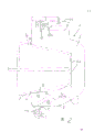
Fig. 1. be the top view of clamping device, a cross section by pivot and securing rod arranged, and the elevation of wanting connected end web is arranged, these webs can be vertically with/or flatly settle.
Fig. 2, represent roughly corresponding a kind of improved form with magnification ratio with Fig. 1, compared to Figure 1 be positioned to for wanting the bonding surface between connected two blocks of end webs to become mirror image than pivot and securing rod, compared to Figure 1 so that anchor clamps can arbitrarily be placed in a certain position or be in according to Fig. 2 is opposite position, these anchor clamps have a horizontal openable opening that penetrates that supplies pivot to use, and can remove in order to make anchor clamps.
Fig. 3 is the partial view of anchor clamps shown in Figure 2, a cross section is arranged by spring load latch, the horizontal cut that penetrates opening that is used to pivot to provide.
Fig. 4 is the rear elevation of template, and securing rod or pivot are arranged in the inboard of all four limit end webs.
Fig. 5 is the top view of Fig. 4 template.
The overall usefulness 1 of linkage indicates, template 2 has and is erected at its edge, and with template surface 3 rectangular end webs 4, surrounded by whole anchor clamps 5, the use location of anchor clamps 5 represents with solid line, clamp the end web 4 of wanting connected template 2 aligned with each other around.
In this case, anchor clamps 5 can rotate to the release position that dots around the axle 6 that is parallel to approach end web 4, and can rotate to its use location from release position on the contrary.
When the use location, anchor clamps 5 can clamp with the free clamp arm 7 that leaves gantry post, and pivot 6 withstands the bar parallel with another piece end web 8 in the mode that also will illustrate, like this, with two flat against end web 4 with shown in the mode that is pressed against each other clamp.
For the template 2 on aligned position is fixed together and necessary further aligning in clamping, anchor clamps 5 clamp on the surface 9 of opposing end web 4 with forming block when its use location at least partly each other, in addition, when this use location, the flat anchor clamps inboard accordingly that leans against of the free edge 4a of end web 4 is in order to aim at it well.Rely on bar 8 to tighten free clamp arm 7, a telescopic arm 10 is provided, telescopic arm 10 roughly can slide along the direction of free pinching end, and clamp it below bar 8 back of sliding.-as shown in the figure.By referring to Fig. 1 and Fig. 2, people clearly realize that at this position telescopic arm 10 and block anchor clamps 5, therefore anchor clamps 5 are put back.
Telescopic arm 10 is to install like this.Be contained on the protrusion 11 in free clamp arm 7 outsides, this protrusion 11 can be swung by bar 8, and when the use location also and a distance of crossing telescopic arm 10 arranged between the bar 8.Shown in model, free clamp arm 7 can be swung between end web 4 and securing rod 8 and enter the use location, promptly can not swing a side that surpasses the bar 8 that deviates from end web 4, and is captured between the there.
Sliding extension arm 10 faces toward bar 8 with itself and side 10a, and oblique gradient by its glide direction and guide rail arrives the direction of illustrated latched position along sliding with respect to telescopic arm.Thereby upper side 10a at first contacts with the downside 8a of corresponding bar 8, further clamps when promoting telescopic arm 10, and anchor clamps 5 compress two end webs 4 in desired mode.In order to transmit enough big active force, telescopic arm 10 can slide on the support 12 that dots, and support is roughly parallel with the downside 8a of bar, and in fact the gradient for upper side 10a forms assembly key.The guide rail on leaning against support 12, telescopic arm also can lead with a bolt device 13 in the outside of anchor clamps, in addition, also be for it can not be got loose from the elongated slots 14 of projection or other similar item, as from being clear that institute's representation model.
Telescopic arm 10 has the protrusion 15 of himself in institute's representation model, is used for the active force of the instrument that bears, for example effect of hammer, and protrusion 15 deviates from the end of fastening end at telescopic arm, and support 12 and clamp arm 7 are the opposite projection of protrusion 11.Like this, telescopic arm 10 can be used instrument, beats its use location, also can beat protrusion 15 by rightabout it is unclamped, in fact, consequently telescopic arm 10 can be used as if a push-and-pull check mechanism, play such effect, in addition, also play a part the wedge of having described.
Mentioned the each other outboard wheel profile of flat two block end webs 4 leaning on of the nearside wheel profile of anchor clamps 5 greater than correspondence, yet, in institute's representation model, free clamp arm 7 is having a block 16 towards the anchor clamps inboard near its free end, and side is blocked end web at the bar place.The upper side 9 of these piece end web 4 remainders thereby maintenance are free, so that the difference of its size and allow clearance do not have passive effect, and in fact, the upper side 9 of end web 4 clamping region that enters contact farthest separates in all cases, form desired clamping and the best leverage that is connected, like this, two blocks of end webs 4 are along the upper side 9 that deviates from template 2 contact surfaces in the cross section, constitute roughly trapezoidal in that the oblique free end 4a of cross section is common, so chucking opening also is trapezoidal basically.Therefore, even rarer leaving more than the end web 4, anchor clamps 5 can swing to the use location and make two blocks of end webs 4 more close each other in this case, and they are aimed at.
For when anchor clamps 5 are opened, it can fully freely be swung, and when anchor clamps were in its make position, side, pivot place also can lean against contact securely on the end web 4, and the dead eye 18 of gantry post 19 is eccentric; Dot the open position of anchor clamps 5, anchor clamps 5 have a tangible distance with adjacent end web 4, approximately corresponding to the eccentric throw of twice, and therefore when make position, the interior side compression end web 4 of available anchor clamps.
Have a following side plane 8a at cross section king-rod 8, locate in order to make telescopic arm 10 well, and constitute by a square tube, thereby the cross section of its downside roughly is orientated parallel with the glide direction of telescopic arm 10 at institute's representation model king-rod 8.In the case by orientation and guide rail support thing 12 referring to elongated slots 14, people find out that the glide direction of telescopic arm 10 is in relatively perpendicular to the folded angle of the vertical line of template surface 3 than itself and free clamp arm 7 or itself and can be little by the folded angle of the vertical line that is placed on the inboard on the end web 4, the end web 4 that this not only allows the clamping pressure of clamp arm 7 to impose on it to face toward, and simultaneously shown in the use location on pin anchor clamps 5 on request, stoped undesirable big opening.
The pivot 6 and the securing rod 8 that are used for anchor clamps 5 can pass the web 20 of relevant template 2 with suitable manner by favourable, and template meets at right angles with wanting connected end web, and these webs 20 are fixed.Integral body clamping device can be not released as a result, obviously quite growing in the web 20 of distance, and several anchor clamps 5 can be located on the axle 6 compartment of terrain.
The operation of this clamping device 1 is very easy, because after two templates 2 put together, only needs anchor clamps or a plurality of anchor clamps 5 are swung to their make position.And pin with sliding extension arm 10, with the connection of two templates 2 obtaining the big active force of usefulness.It also is easy equally opening this device and removing template.
A kind of improved model particularly also has fixed bar 8 about anchor clamps 5, is illustrated among Fig. 2 to Fig. 5, although retrofit and change, provides corresponding reference number corresponding to the part of above-mentioned model here.
In second kind of model, anchor clamps 5 are provided with a slotted hole 19a who penetrates as pivot suspension 19 to its pivot 6, the breach 21 that has at least part to open and close on the edge in hole, notch length is corresponding with the section of pivot 6, therefore if make a breach 21, can remove anchor clamps 5 from pivot 6 thus, pivot 6 is to shift out in the transverse direction breach 21 that moves towards from pivot.
This slotted hole 19a that penetrates that is used for pivot 6 is an elongated hole, when anchor clamps 5 are in the use location, transverse direction along template surface 3, in institute's representation model, along with the roughly rectangular direction of template surface, and this breach 21 at the slotted hole edge is positioned at the end near this slotted hole, deviate from template surface 3 from Fig. 2 and Fig. 3 as can be seen, breach is arranged in the zone of lengthwise wall of slotted hole, rather than is directly arranged in the end, is actually and is deviating from the side of actual chuck.Therefore after the afterbody of template 2 was opened, anchor clamps can easily be removed from template 2, and pivot 6 usefulness breach 21 get loose.
The closure of breach 21 is formed with pin 23 in institute's representation model, pin 23 can be that backspring 22 promotes with a restoring force, yet, the spring bow also can gap crossing, be similar to an aperture on the jewel clasp, or the horizontal interlayer that ejects in breach is set, be similar to a spring clip.Yet, because closure must not crossed whole breach 21, also just enough the pin 23 that it pushes back so be stretched on breach 21 with one so long.
In the model shown here, the pivot 6 that clamp with sliding extension arm or securing member 10 and fixed bar 8 are arranged on equal height, and its corresponding spacing is relevant with the end web 4 of the template 2 that will connect.This moment, they had corresponding circular section in institute's representation model, and feasible pivot 6 and the bar 8 of using two templates of anchor clamps 5 connections is set to minute surface and is symmetrical in the contact plane that extends through two blocks of end webs 4 between the template.Because anchor clamps 5 can be from the breach opened 21 dismountings of slotted hole described above.Although a common clamper is can be not released, pivot 6 and securing rod 8 can exchange each other.And, must notice forever that when template is linked together, be suitable for a pivot is placed on a side, and securing rod is suitable for and is placed on a side of wanting connected junction to face toward, this point will no longer need according to the model of Fig. 1 in this model.
Can see that in Fig. 4 pivot 6 and/or bar 8 are that all four end webs 4 along a rectangle template 2 are provided with, corresponding interval is all arranged on each end web, therefore, in order to increase the height of the template wall of being formed by template 2, vertically hold up with their long limits, turn over 90 ° of clampings with template is corresponding, make longer sides lie in initial appointment template than minor face, can finish connection in this position equally with anchor clamps 5.
Certainly also allow the plate face of these templates that height tolerance is arranged mutually, because anchor clamps can be connected at any place of pivot 6 with securing rod 8 in all cases.
From Fig. 4, can also see, pivot 6 and bar 8 are parallel with end web than minor face with rectangle template 2, concordant with the pivot 6 of the other longitudinal edge of template 2 in all cases with bar 8, template 2 is vertical with them and has preferably and be connected, for example, weld together with them, form the additional support thing of monoblock template 2, make the power that occurs by anchor clamps 5 can be delivered in the support and web of template, here Fig. 4 also illustrates pivot 6 and bar 8 is arranged between the ribs 20 of template plate 2, like this can be laterally trend by ribs, and bar 8 and pivot 6 are parallel to these ribs 20, and parallel to template plate 2 than minor face, and have at least one the supporting 24, in institute's representation model, three such supportings 24 are arranged with respect to end web 4.Facing to supporting 24 possibilities of ribs 20, as shown in Figure 4, necessary corresponding length is a little.
Stack up draws a template 2, can be at any edge be connected with adjacent template with difference in height arbitrarily with it, also has bar and axle to support them in addition.In Fig. 2 and model shown in Figure 3, although the holder of anchor clamps 5 can not unclamp, and anchor clamps 5 can exchange, so the installation of template is easy.
Claims (22)
1, a kind of linkage (1) that anchor clamps (5) are arranged that is used for template (2) comprises that template edge has and the rectangular end web of template surface (3) (4), with anchor clamps (5) the pinching end web that is in the use location; And anchor clamps rotate around an axle that is parallel to an end web, enter release position and enter the use location; Can clamp with free clamp arm in the use location, deviate from the arm rest that freely clamps of gantry post and the bar or other similar item that are parallel to another piece end web and clamp; Like this with two flat each other against end web be pressed together, it is characterized in that, the anchor clamps (5) that are in the use location clamp the surface (9) of opposing each other end web at least partly with the block that forms, as for free clamp arm (7) is clamped in bar (8), one telescopic arm (10) then is set thereon, slide along the direction that is roughly free pinching end, the back of sliding is at the below of bar (8) chucking.
2, according to the described device of claim 1, be characterised in that, when being in the use location, the flat inboard that leans against anchor clamps of the free margins (4a) of end web (4).
According to claim 1 or 2 described devices, be characterised in that 3, telescopic arm (10) is installed on the protrusion of free clamp arm (7), clamp arm can be swung by bar, leaves a spacing when being in the use location and between the bar.
According to the described device of claim 1, be characterised in that 4, towards bar (8), the bar inclination that compresses along its glide direction and below is oblique, thereby gradient appears at the opposite of rail plate with its upper side (10a) for sliding extension arm (10).
According to the described device of claim 1, be characterised in that 5, telescopic arm leans against on the support of downside (8a) trend that is roughly parallel to bar and slides, and forms wedge.
According to claim 4 or 5 described devices, be characterised in that 6, fastening and chucking wedge also has its guide rail of bar downside dorsad, regulates with latch (13) in the elongated slots (14) or similar item device, so can not get loose.
According to the described device of claim 1, be characterised in that 7, free clamp arm (7) can be swung the use location that arrives between end web (4) and the securing rod (8).
8, according to claim 4 or 5 described devices, be characterised in that telescopic arm (10) has a protrusion (15) at the end place that it deviates from the fastening end, be used for the active force of the instrument that bears, the opposite at guide rail (12) and clamp arm (7) is protruded in the particularly effect of hammer.
9, according to claim 1 or 2 described devices, be characterised in that, the inboard profile of anchor clamps (5) is greater than the lateral profile of the flat two blocks of end webs (4) that lean on each other of correspondence, thereby free clamp arm (7) is having a protrusion (16) near its free end, point to the inboard of anchor clamps, just as a brake block, lean against on the end web in the side that bar is arranged.
10, according to the described device of claim 1, be characterised in that two blocks of end webs (4) side (9) thereon locate to deviate from the oblique cross section that passes through of its contact surface, from template surface (2) to its free end (4a), common form roughly trapezoidal, and that chucking opening is basically is trapezoidal.
11, according to the described device of claim 1, be characterised in that, the dead eye (18) of anchor clamps gantry post (19) is eccentric, when the enable possition, and a tangible distance is arranged between the abutting end web (4), its respective distances is about the twice eccentric throw, and when make position, then presses end web (4) with the inboard of anchor clamps.
12, according to claim 1 or 4 described devices, be characterised in that, bar (8) has a following side plane (8a) to be used as the location of telescopic arm in the cross section, for example constitute with box section or other similar item, and downside is by the glide direction orientation that is roughly parallel to telescopic arm (10).
13, according to claim 1 or 5 described devices, be characterised in that the folded acute angle of the vertical line of the glide direction of telescopic arm (10) and template surface (3) maybe can be placed in the folded angle of the vertical line of clamp arm inboard of end web (4) than itself and free clamp arm (7) little.
14, according to claim 7 or 11 described devices, be characterised in that the pivot (6) that is used for anchor clamps (5) also has securing rod (8), passes through from the web (20) of template (2), template (2) be rectangular with wanting connected end web (4), and and/or these webs is fixed.
15, require 7 described devices according to aforesaid right, be characterised in that,, make it and in one of pivot of especially firmly installing, to get loose the anchor clamps location.
16, according to the described device of claim 7, be characterised in that, anchor clamps (5) have an opening that penetrates (19a) to be used for placing pivot (6), and the edge of opening has a closeable breach in part (21) at least, and its length at least should be corresponding with the cross section of pivot (6).
17, according to the described device of claim 16, be characterised in that, the opening (19a) that penetrates that is used for pivot (6) is an elongated hole, use location in anchor clamps (5), transversely extend in the direction of template surface (3), and that the local at least closeable breach in the edge of elongated hole (21) is positioned at is specific, or approaches the end that this elongated hole deviates from template surface (3).
According to described device one of in claim 16 or 17, be characterised in that 18, the closure of the breach (21) of the used elongated hole outline of pivot is with pin (a 23) baffle plate or similar item combination, can be pushed into interior by a restoring force or spring (22).
19, according to the described device of claim 7, be characterised in that, pivot (6) and be installed in sustained height with the bar (8) that sliding extension arm (10) is clamped, and corresponding distance is relevant with the end web (4) of wanting connected template (2), and a circular cross-section is particularly accordingly arranged, and making the pivot (6) of two connected templates and bar (8) be arranged to for the plane by the mating face between the end web of two templates (4) is the minute surface symmetry.
According to the described device of claim 19, be characterised in that 20, pivot (6) and/or bar (8) are all the four blocks of end webs (4) along rectangle template (2), be provided with by corresponding distance.
21, according to claim 19 or 20 described devices, be characterised in that, pivot (6) and/or bar (8) parallel by rectangle template (2) than minor face and end web, concordant with pivot 6 in all cases with bar 8, template 2 is vertical with them, and have preferably to connect, as welding together with them.
22, according to the described device of claim 20, be characterised in that, in all cases, pivot (6) and/or bar (8) are between the ribs (20) that is positioned in template (2), and/or horizontal stroke by them, and bar (8) and/or pivot (6) are parallel by such ribs (20), and be parallel to template (2) than minor face, preferably have at least a supporting (24) to lean against on an end web (4) and/or the ribs (20).
Applications Claiming Priority (2)
| Application Number | Priority Date | Filing Date | Title |
|---|---|---|---|
| DE3724873.1 | 1987-07-28 | ||
| DE19873724873 DE3724873A1 (en) | 1987-07-28 | 1987-07-28 | CONNECTING DEVICE FOR CONTROL PANELS |
Publications (2)
| Publication Number | Publication Date |
|---|---|
| CN1032206A CN1032206A (en) | 1989-04-05 |
| CN1015190B true CN1015190B (en) | 1991-12-25 |
Family
ID=6332471
Family Applications (2)
| Application Number | Title | Priority Date | Filing Date |
|---|---|---|---|
| CN88104673A Expired CN1015190B (en) | 1987-07-28 | 1988-07-28 | Connecting device for shutterings |
| CN88104677A Expired CN1019220B (en) | 1987-07-28 | 1988-07-28 | Fastening clamp for connecting edges of slabs |
Family Applications After (1)
| Application Number | Title | Priority Date | Filing Date |
|---|---|---|---|
| CN88104677A Expired CN1019220B (en) | 1987-07-28 | 1988-07-28 | Fastening clamp for connecting edges of slabs |
Country Status (19)
| Country | Link |
|---|---|
| US (1) | US5064163A (en) |
| EP (1) | EP0370034B1 (en) |
| JP (1) | JPH02504408A (en) |
| KR (1) | KR930001034B1 (en) |
| CN (2) | CN1015190B (en) |
| AT (1) | ATE87993T1 (en) |
| AU (1) | AU616678B2 (en) |
| CA (1) | CA1303378C (en) |
| DE (2) | DE3724873A1 (en) |
| DK (1) | DK167125B1 (en) |
| ES (1) | ES2009631A6 (en) |
| HK (1) | HK115493A (en) |
| IL (1) | IL87215A (en) |
| MA (1) | MA21340A1 (en) |
| MY (1) | MY104848A (en) |
| PH (1) | PH27075A (en) |
| PT (1) | PT88101B (en) |
| TR (1) | TR23501A (en) |
| WO (1) | WO1989001083A1 (en) |
Families Citing this family (13)
| Publication number | Priority date | Publication date | Assignee | Title |
|---|---|---|---|---|
| US6322046B1 (en) | 1999-02-16 | 2001-11-27 | Michael R. Yurick | Form panel clamp |
| DE102004039470B4 (en) * | 2004-08-14 | 2006-06-08 | Peri Gmbh | Concrete encased lock comprises a first lock part having a hook and a second lock part having a receiving shoe for the hook |
| ES2303434B1 (en) * | 2006-03-28 | 2009-06-03 | Inveral, S.A. | PROCEDURE FOR THE MANUFACTURE OF A UNION DEVICE FOR COOLED PANELS AND DEVICE OBTAINED ACCORDING TO SUCH PROCEDURE. |
| DE102008032338A1 (en) | 2008-07-09 | 2010-01-14 | Noe-Schaltechnik Georg Meyer-Keller Gmbh + Co. Kg | Connecting device for stackable formwork elements, has upper contact surface and lower contact surface placed at upper and lower ends of carrier extended to other side of formwork body and mounted at formwork body |
| DE202008009235U1 (en) | 2008-07-09 | 2008-09-11 | Noe-Schaltechnik Georg Meyer-Keller Gmbh + Co. Kg | Device for connecting add-on formwork elements |
| DE102008064551B4 (en) * | 2008-12-31 | 2013-01-10 | Hans Peter Jung | Connecting device for formwork panels |
| CN101984202A (en) * | 2010-11-05 | 2011-03-09 | 湖南长大建设集团股份有限公司 | Clamp for reinforcing cast-in-site structure template |
| CN102296811B (en) * | 2011-06-15 | 2014-04-02 | 天颂建设集团有限公司 | Cushion block for fixing concrete flanged side mold |
| DE102012214396A1 (en) * | 2012-08-13 | 2014-02-13 | Harsco Infrastructure Services Gmbh | Wall formwork with connection device |
| CN103437546B (en) * | 2013-09-12 | 2016-08-17 | 云南建工建材科技有限责任公司 | A kind of combinative structure aluminum alloy mould plate |
| FR3054184B1 (en) * | 2016-07-22 | 2018-07-13 | Peugeot Citroen Automobiles Sa | BUMPER WITH LUMINOUS DEVICE OF A MOTOR VEHICLE |
| CN210289114U (en) * | 2019-02-15 | 2020-04-10 | 浙江中益建材科技有限公司 | Quick assembly disassembly anchor clamps |
| CN111950109A (en) * | 2019-05-14 | 2020-11-17 | 大族激光科技产业集团股份有限公司 | Pipe cutting clamp and optimization method thereof |
Family Cites Families (10)
| Publication number | Priority date | Publication date | Assignee | Title |
|---|---|---|---|---|
| CA617554A (en) * | 1961-04-04 | Rocform Corporation | Corner clamp for prefabricated wall forms | |
| GB789402A (en) * | 1955-09-13 | 1958-01-22 | Ignaz Zeissl | Improvements in or relating to clamps for concrete formwork and the like |
| FR1205905A (en) * | 1957-04-16 | 1960-02-05 | Schnell Hico Italiana | Improvements made to profile assembly devices, in particular those forming part of formwork for reinforced concrete constructions |
| US2964294A (en) * | 1958-09-04 | 1960-12-13 | Symons Clamp & Mfg Co | Waler clamp for concrete wall forms |
| US3363877A (en) * | 1965-04-05 | 1968-01-16 | Gates & Sons | Sliding tie-end latch assembly for gang forms |
| US3550898A (en) * | 1969-01-06 | 1970-12-29 | Tru Wall Concrete Forming Ltd | Concrete wall forms |
| AU1891770A (en) * | 1970-08-18 | 1972-02-24 | Hilton Brooks Samuel | Shuttering clip means |
| IL45574A (en) * | 1974-08-30 | 1978-12-17 | Shahar M | Set for assembling shuttering |
| US4188017A (en) * | 1978-10-10 | 1980-02-12 | Gerhard Dingler | Tensioning device for frame pieces |
| AU520043B2 (en) * | 1979-08-07 | 1982-01-14 | Gerhard Dingler | Tensioning device for shuttering |
-
1987
- 1987-07-28 DE DE19873724873 patent/DE3724873A1/en active Granted
-
1988
- 1988-07-16 EP EP88905707A patent/EP0370034B1/en not_active Expired - Lifetime
- 1988-07-16 AU AU20739/88A patent/AU616678B2/en not_active Ceased
- 1988-07-16 WO PCT/DE1988/000440 patent/WO1989001083A1/en active IP Right Grant
- 1988-07-16 JP JP63505837A patent/JPH02504408A/en active Pending
- 1988-07-16 US US07/459,710 patent/US5064163A/en not_active Expired - Fee Related
- 1988-07-16 DE DE8888905707T patent/DE3880144D1/en not_active Expired - Fee Related
- 1988-07-16 AT AT88905707T patent/ATE87993T1/en not_active IP Right Cessation
- 1988-07-16 KR KR1019890700181A patent/KR930001034B1/en not_active IP Right Cessation
- 1988-07-26 IL IL87215A patent/IL87215A/en not_active IP Right Cessation
- 1988-07-26 PH PH37283A patent/PH27075A/en unknown
- 1988-07-26 PT PT88101A patent/PT88101B/en not_active IP Right Cessation
- 1988-07-27 CA CA000573113A patent/CA1303378C/en not_active Expired - Lifetime
- 1988-07-27 MY MYPI88000841A patent/MY104848A/en unknown
- 1988-07-28 CN CN88104673A patent/CN1015190B/en not_active Expired
- 1988-07-28 ES ES8802375A patent/ES2009631A6/en not_active Expired
- 1988-07-28 CN CN88104677A patent/CN1019220B/en not_active Expired
- 1988-07-28 TR TR549/88A patent/TR23501A/en unknown
- 1988-07-28 MA MA21583A patent/MA21340A1/en unknown
-
1990
- 1990-01-29 DK DK023390A patent/DK167125B1/en not_active IP Right Cessation
-
1993
- 1993-10-28 HK HK1154/93A patent/HK115493A/en unknown
Also Published As
| Publication number | Publication date |
|---|---|
| EP0370034B1 (en) | 1993-04-07 |
| MY104848A (en) | 1994-06-30 |
| CN1019220B (en) | 1992-11-25 |
| ATE87993T1 (en) | 1993-04-15 |
| CN1032206A (en) | 1989-04-05 |
| ES2009631A6 (en) | 1989-10-01 |
| IL87215A (en) | 1991-04-15 |
| JPH02504408A (en) | 1990-12-13 |
| DE3724873C2 (en) | 1990-10-11 |
| DE3724873A1 (en) | 1989-02-09 |
| MA21340A1 (en) | 1989-04-01 |
| DE3880144D1 (en) | 1993-05-13 |
| CA1303378C (en) | 1992-06-16 |
| DK23390D0 (en) | 1990-01-29 |
| KR930001034B1 (en) | 1993-02-13 |
| US5064163A (en) | 1991-11-12 |
| CN1035862A (en) | 1989-09-27 |
| AU616678B2 (en) | 1991-11-07 |
| DK167125B1 (en) | 1993-08-30 |
| HK115493A (en) | 1993-11-05 |
| EP0370034A1 (en) | 1990-05-30 |
| TR23501A (en) | 1990-02-02 |
| WO1989001083A1 (en) | 1989-02-09 |
| KR890701857A (en) | 1989-12-22 |
| AU2073988A (en) | 1989-03-01 |
| PT88101A (en) | 1989-12-29 |
| IL87215A0 (en) | 1988-12-30 |
| PH27075A (en) | 1993-02-01 |
| PT88101B (en) | 1994-01-31 |
| DK23390A (en) | 1990-01-29 |
Similar Documents
| Publication | Publication Date | Title |
|---|---|---|
| CN1015190B (en) | Connecting device for shutterings | |
| US4857020A (en) | Tap connector | |
| US4430019A (en) | Connector assembly | |
| EP0293240A2 (en) | Panel locking system | |
| US20030218108A1 (en) | Apparatus for quick fixation of a device to a tripod head | |
| GB2298090A (en) | Unlocking device | |
| US7992836B2 (en) | Slab formwork system and method for preparation of slab formwork system of this type | |
| US6767154B1 (en) | Turnbuckle device | |
| JPS6274767A (en) | Fixing device for cylindrical body | |
| JPH0266387A (en) | Pipe hold-down | |
| GB2592433A (en) | Hop-up scaffold bracket | |
| US5040916A (en) | Scaffold fitting | |
| US5651914A (en) | Support with removable support head | |
| CN218715028U (en) | Clamp structure | |
| CN1767970A (en) | Device for fixing a housing, in particular of a motor-vehicle battery, to a support. | |
| US20010032492A1 (en) | System for anchoring frames to a platform | |
| CN116475974A (en) | Clamping device | |
| JPH0115416B2 (en) | ||
| WO1993009006A1 (en) | Cargo container securing device | |
| US6651388B1 (en) | Follower using pivoting retaining arms for retaining a window pane | |
| GB2095358A (en) | Scaffolding joints | |
| GB2240804A (en) | Scaffolding coupler | |
| US11472674B2 (en) | Lifting clamp including pivot leg | |
| JP2660811B2 (en) | Suspension support bracket | |
| EP3162957A1 (en) | Safety device for preventing rail buckling and movement |
Legal Events
| Date | Code | Title | Description |
|---|---|---|---|
| C06 | Publication | ||
| PB01 | Publication | ||
| C10 | Entry into substantive examination | ||
| SE01 | Entry into force of request for substantive examination | ||
| C13 | Decision | ||
| GR02 | Examined patent application | ||
| C14 | Grant of patent or utility model | ||
| GR01 | Patent grant | ||
| C19 | Lapse of patent right due to non-payment of the annual fee | ||
| CF01 | Termination of patent right due to non-payment of annual fee |