CN101516627A - Apparatus for applying substance to sheetlike substrates - Google Patents
Apparatus for applying substance to sheetlike substrates Download PDFInfo
- Publication number
- CN101516627A CN101516627A CNA2007800340425A CN200780034042A CN101516627A CN 101516627 A CN101516627 A CN 101516627A CN A2007800340425 A CNA2007800340425 A CN A2007800340425A CN 200780034042 A CN200780034042 A CN 200780034042A CN 101516627 A CN101516627 A CN 101516627A
- Authority
- CN
- China
- Prior art keywords
- supporting arrangement
- substrate
- lowering
- spraying material
- material head
- Prior art date
- Legal status (The legal status is an assumption and is not a legal conclusion. Google has not performed a legal analysis and makes no representation as to the accuracy of the status listed.)
- Pending
Links
Images


Classifications
-
- B—PERFORMING OPERATIONS; TRANSPORTING
- B41—PRINTING; LINING MACHINES; TYPEWRITERS; STAMPS
- B41J—TYPEWRITERS; SELECTIVE PRINTING MECHANISMS, i.e. MECHANISMS PRINTING OTHERWISE THAN FROM A FORME; CORRECTION OF TYPOGRAPHICAL ERRORS
- B41J3/00—Typewriters or selective printing or marking mechanisms characterised by the purpose for which they are constructed
- B41J3/407—Typewriters or selective printing or marking mechanisms characterised by the purpose for which they are constructed for marking on special material
- B41J3/4078—Printing on textile
-
- B—PERFORMING OPERATIONS; TRANSPORTING
- B41—PRINTING; LINING MACHINES; TYPEWRITERS; STAMPS
- B41J—TYPEWRITERS; SELECTIVE PRINTING MECHANISMS, i.e. MECHANISMS PRINTING OTHERWISE THAN FROM A FORME; CORRECTION OF TYPOGRAPHICAL ERRORS
- B41J3/00—Typewriters or selective printing or marking mechanisms characterised by the purpose for which they are constructed
- B41J3/28—Typewriters or selective printing or marking mechanisms characterised by the purpose for which they are constructed for printing downwardly on flat surfaces, e.g. of books, drawings, boxes, envelopes, e.g. flat-bed ink-jet printers
Abstract
An apparatus for applying substance to sheetlike substrates (10), in particular to textiles, carpets and films, comprises at least one application station (2) which applies the substance to the substrate (10) in the width direction and longitudinal direction. The application station (2) is equipped with a device (9) which accommodates the substrate (10) and with a supporting device (3) which has at least one substance spray head (4) with spray nozzles (42) which are arranged in a stationary manner and are distributed over the entire application width. The spray head supporting device (3) and the substrate (10) are arranged such that they are moveable relative to each other in the direction of longitudinal application. The spray head supporting device (3) and a surface (90) receiving the substrate (10) are arranged in a vertically displaceable manner relative to each other by means of at least one lifting device (5, 6) in such a manner that the substance spray head (4) passes into at least one application working position and into at least one position releasing the stationary nozzles (42) along the supporting device (3) for maintenance.
Description
Technical field
The present invention relates to a kind of being used for is coated in planar substrate with material, especially textile, carpet, device on the film, it includes at least one coating station, this coating station on the width He on the longitudinal direction is being coated in material on the substrate, wherein the coating station is provided with the device of an admittance substrate and is provided with a supporting arrangement, the latter is arranged on the substrate width at least basically and has a spraying material head at least, spraying material head constitutes by the fixed and arranged that design is distributed in the nozzle on the entire coating width, and wherein spraying material head supporting arrangement and substrate be arranged to mutually can relative motion on the direction of longitudinal application.
Background technology
The dyestuff shower nozzle that belongs to the coating station of this type of device has a plurality of nozzles that eject material, they are fixedly placed on the whole length of supporting arrangement, for example along a bearing cross beam, Cheng Yilie or several row are so that reach the whole width of the substrate of the coating material of wanting simultaneously.A kind of device according to this type of can be arranged for the coating of various materials, in particular for printing, but also is used for coating and/or dip-dye.Known devices has printing machine, and they have several printing stations.The spraying material head of each printing station all is furnished with one or more dyestuffs.A kind of substrate of printing on the lining cloth that place carried and continuously under dye nozzles, and the workplace that for example becomes some millimeters is apart from the other process of these nozzles.This is meant the printing machine with nozzle, and these nozzles are controlled by means of electronic circuit is digital.Machine can be with high relatively speed operation, this be because link up, fixing printing crossbeam in other words this nozzle that is fixedly placed on its whole length allow substrate, just especially banded material traversed by perpendicular to the printing crossbeam continuously, lengthwise movement incessantly.This compares with following such digital printing machine has tangible advantage, and this digital printing machine comes work with a kind of carriage system.Just must on a crossbeam, there be several balladeur trains that nozzle is housed to move back and forth back and forth, so that reach printing width.Therefore this has determined banded material to realize a kind of interrupted motion process under balladeur train-dyestuff shower nozzle and has limited print speed printing speed, and may produce printing error, for example connects bandedly, and this is owing to be not accurate feed motion from stroke to stroke.
In according to this type of device, be arranged in continuously whole work-/fixed nozzle on the printing width needs special measure certainly and is used for safeguarding and cleaning.Be used for printing machine that textile is printed usually its printing width at 1.5m to the scope that has exceeded 3m.Nozzle should be as much as possible in an operation and/or side by side can be near so that clean and safeguard on the whole working width, thereby avoid or reduced pause-or debug the time to a great extent.Chromatic printing machine should be can be breaks in production ground not under certain condition, reliably and apace realizes dyestuff-and/or the conversion of pattern.Known with regard to this target have some digital printing machines, printing station is equipped with a spraying material head-supporting arrangement respectively in these printing machines, it can whole, corresponding to work-/move to perpendicular to the substrate stroke on the length of printing-width on the position by the printing equipment (WO-A1-01/40564).Have this pattern, otherly towards the limit can except the adjustment space that is used for printing machine own, in fact also need an onesize space at the printing machine of the printing crossbeam that moves on the straight line, be used for making the printing crossbeam that is shifted out in the printing position move to its debug-/service position, for example on guide rail.When the printing crossbeam also must be considered when mobile like this along straight line: have several printing stations a printing machine the printing crossbeam service-/can be approaching at least one vertical limit of printing crossbeam on the maintenance position.In any case this make printing station all must be in couples with enough big pitch arrangement on printing machine so that allow its service-/maintenance position on walking inspection between two printing crossbeams (WO-A1-01/40564, Fig. 3).
Summary of the invention
The objective of the invention is to: improve maintenance, consider that especially the accessibility by minimum space also reduces the operation that is used to safeguard the required time and influences device as small as possible along the fixing nozzle of supporting arrangement.A plurality of coatings station should be with little pitch arrangement on applying device.Pause-or the time of debuging is little.Especially should needn't stop the grown place at certain condition and on printing machine, carry out dyestuff fast-and/or the conversion of pattern.
Described purpose reaches in conjunction with the feature of beginning institute array apparatus by the following method according to the present invention: a supporting liner bottom surface with spraying material head-supporting arrangement and the substrate catching device of the nozzle on the application width of being arranged in, be arranged to relatively to adjust mutually height by means of at least one lowering or hoisting gear, permit these fixing nozzles on the position that supporting arrangement is safeguarded thereby spraying material head enters at least one application job position and enters at least one.Arriving at least one by means of the operating position that can realize making spraying material head-supporting arrangement from an adjacent substrate according to lowering or hoisting gear of the present invention has on the position that spacing leaves, whole nozzle can be approaching along bearing cross beam on the described position of the latter, is used for simultaneously cleaning or safeguarding.Therefore lowering or hoisting gear directly is arranged on the frame of applying device, just strengthens by lifting or has reduced the relative spacing between substrate and spraying material head supporting arrangement so that clean and safeguard.Can consider such form of implementation, the substrate continuing surface be descended be used to set up maintenance position, and lift and be used to set up the operating position.The spraying material head supporting arrangement can be walked close to reach in minimum zone, is used for handling, and is used for cleaning and/or safeguarding.
A kind of have a plurality of, in the device at the parallel coating station that is arranged side by side of the delivery stroke arow of substrate, have special advantage.The coating station can be arranged closely especially, that is to say that mutual spacing is less relatively.Open when being used for safeguarding when one or several spraying material head supporting arrangements and substrate separation, can make to have at least the device at another one coating station and continue operation and be used to produce.
A kind of special design is: coating station or a plurality of coatings station have two lowering or hoisting gears that are provided with two lifting positions at least and are used to carry out Height Adjustment, this device is arranged on the fixture of applying device, wherein first lifting position, bottom set up an operating position at least by one and set up also aptly that at least one is static-and/or first lowering or hoisting gear of maintenance position set up, and lifting position, second top is set up by second lowering or hoisting gear, this lowering or hoisting gear rises at least one top with spraying material head-supporting arrangement, on the come-at-able from the outside maintenance position, wherein suitable is that supporting arrangement is being preferably under the level and can swinging on the limit at upper position.At least by means of second lowering or hoisting gear make spraying material head-supporting arrangement arrive a top, from the outside on the come-at-able maintenance position.Second lowering or hoisting gear has a bearing arrangement that has pressure apparatus aptly, makes spraying material head-supporting arrangement lift the position from top by this pressure apparatus and overcomes stop pressure arrive the bottom and lift on the position under the gravity effect.Particularly advantageous is that the part of two lowering or hoisting gears is structure members, the bearing that is used to adjust height that these parts have supporting arrangement and arrange in its end.Bearing is arranged on the supporting arrangement aptly, has used the drive unit that control is arranged and has made highly and can adjust.The lifting structure parts also can particularly advantageously be arranged for turntable bearing and be connected, and can make supporting arrangement center on a axis of oscillation by means of this bearing and swing to one in the other position of substrate perpendicular to substrate plane, but within device.
Another particularly advantageous measure is: the lifting structure parts are provided with an attending device of work automatically, and this device has fixed nozzle, the removable apparatus of repair parts that a correspondence is disposed at the spraying material head device at least.
According to design advantageous particularly of the present invention and suitable be: if coating a plurality of in other words coatings station, station spraying material head supporting arrangement is separately at least at one end fixed and supported by means of a rotating disk supporting arrangement, wherein supporting arrangement can be around an axis of oscillation swing, this axis of oscillation is transverse to, and is suitably the substrate plane perpendicular to the substrate catching device.The swinging mounting device is then so arranged and design aptly, the spraying material head supporting arrangement can only left by the Height Adjustment of substrate plane on the position of distance, swing on the maintenance position, in a position that is positioned at substrate next door, but in the device or on the device.Just guaranteed in the locational swing property of spacing: spraying material head-supporting arrangement remain on during in lifting one definite, be not subjected on the direction that oscillating motion influences.Pendulous device be provided with aptly a guiding-and brake apparatus be used to make spraying material head-supporting arrangement lifting, swing and braking.Guiding-advantageously constitute by the slider guide device with brake apparatus.
The little structural shape in a kind of special saving space or space according to device of the present invention has special meaning.Device has at least two aptly and becomes the parallel coating stations that are arranged side by side of row, and each in becoming row coating station arrangement, place a supporting arrangement at least before and/or can swing on the position of lifting of supporting arrangement afterwards cross one or several adjacency, be positioned at the supporting arrangement on the lower position.For example the coating station can be arranged on the so little spacing, crosses three coating stations to such an extent as at least one supporting arrangement lifts can swing on the position at it.
A kind of design is that supporting arrangement is arranged with horizontal length, the substrate catching device remains on substrate in the horizontal plane, and swing-lowering or hoisting gear has a swinging mounting structure that has pressure apparatus, makes supporting arrangement overcome and keep-up pressure and arrive the operating position from lifting the position under the gravity effect by means of this supporting structure.
The present invention is design code aptly: the spraying material head-supporting arrangement that lifts is that 90 ° angle of oscillation can swing on its maintenance position with one at least substantially.Therefore spraying material head-supporting arrangement moves on on the device along the delivery stroke side direction that is parallel to substrate in other words.Spraying material head-supporting arrangement is being shifted out in the working position on this position fully, and nozzle can be easily along supporting arrangement and near getting at, this supporting arrangement is saved ground, space and is stretched and be arranged in the scope of device.This swings to spraying material head supporting arrangement on the 90 °-maintenance position and stretches aptly on carriage being arranged in device or the frame component, is provided with the spraying material head-supporting arrangement at other coating station on this member, can adjust height and can swing.
Supporting arrangement has a vertical limit corresponding to application width aptly, has arranged nozzle on this vertical limit, and wherein supporting arrangement can swung on the direction of faces away from nozzle side on the position of lifting.Nozzle can be approaching especially well so that safeguard in this design.
Spraying material head-supporting arrangement according at least one coating station of a kind of design of the present invention has a lowering or hoisting gear, can make supporting arrangement move at least one operating position and move at least one corresponding matching on the maintenance position of an attending device by means of this lowering or hoisting gear, wherein attending device is equipped with an apparatus of repair parts, these parts can along supporting arrangement move and corresponding matching in fixing nozzle and occupy one at least and make nozzle free maintenance position on the operating position.Apparatus of repair parts is arranged in aptly between substrate plane and the nozzle and can moves.
Attending device can advantageously dispose and act on the cleaning means on the nozzle and/or dispose the securing instrument of the opening that makes nozzle.For example roller or brush are suitable as cleaning means.Movably attending device can not be like this or be additionally provided with an aspirator, the dirt on this aspirator suction lost nozzle.Particularly advantageous with regard to simple design and structural shape is that attending device is arranged on the supporting arrangement.This layout can be included in the structure member together, and these parts can be equipped with the lifting bearing to lowering or hoisting gear in addition aptly.The lifting bearing is arranged on the supporting arrangement aptly, can adjust its height.
In design of the present invention, be provided with first lowering or hoisting gear, it is raised to a corresponding matching on the maintenance position of attending device movably with supporting arrangement, and be provided with second lowering or hoisting gear, it is raised to one with supporting arrangement and compares with described maintenance position equally also to be used to safeguard having in the pendulous device perpendicular to the axis of oscillation of substrate plane aptly on the higher position on substrate plane.
Another design again of the present invention is: applying device has the coating station of a horizontal alignment at least, it has a lowering or hoisting gear, can make spraying material head-supporting arrangement on following operating position is lifted to maintenance position above one by means of this device, corresponding matching has a liftable bridge-type device in this maintenance position, this bridge-type device forms a maintainable platform on this next door that is lifted to the supporting arrangement on the maintenance position, can be near the nozzle of spraying material head device so that safeguard from this platform.The bridge-type device designs aptly like this, it can be added be connected on the applying device.Have a plurality of coatings station according to this applying device of design, wherein the setting of bridge-type device should be able to make it be positioned at the coating station that moves on to a vicinity on the locational supporting arrangement in its underpart with its maintenance platform at one.
Description of drawings
Dependent claims is at the present invention's suitable and favourable design listed and that also have other.According to following description detailed to the represented embodiment of appended sketch suitable especially and favourable structural shape and design of the present invention.
Accompanying drawing is depicted as:
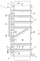
Fig. 1: by a kind of axonometric drawing with eight coating stations shown in Figure 1 according to applying device of the present invention;
Fig. 2 to 4: by the applying device with spraying material head-supporting arrangement shown in Figure 1 lift with swing position on axonometric drawing or vertical view;
Fig. 5: a axonometric drawing that is arranged in the coating station on the device frame according to spraying material head-supporting arrangement of the present invention;
Fig. 6: the side view of pressing the spraying material head-supporting arrangement of structure member form shown in Figure 5;
Fig. 7: the axonometric drawing in the time of on the position of lifting according to the spraying material head-supporting arrangement on the device of invention at and be parallel to device vertical limit swing by shown in Fig. 5 and 6;
Fig. 8: a kind ofly be provided with maintenance-bridge-type device, according to the axonometric drawing of the applying device of invention.
The specific embodiment
A kind ofly having a fixed frame 11 that has top longitudinal bracing 111 and 112 according to applying device 1 of the present invention by shown in Figure 1, is coating station 2,21 to 28 between this longitudinal bracing, and their length for example is 3.2 meters.These coating stations become row to be arranged side by side abreast.Be provided with a kind of roller 91 of substrate catching device 9 in the end of shaped as frame support 111,112.These two rollers in a lateral direction 91 that are arranged in device 1 are in device portal and device outlet, and they have been accepted a kind of planar substrate 10 of webbing form and have made it mobile guide.Webbing is positioned under the coating station 21 to 28, and is parallel to the longitudinal direction of device 1, moves continuously with a unshowned conveying device on throughput direction F.A sequence of webbing or single substrate also can be by the webbing of a conveying, and for example a kind of back cloth supports.
Each coating station 2 supporting arrangement 3 with profiled beam 31 shapes, it is made of a hollow crossbeam, and this crossbeam is bearing on the longitudinal bracing 111,112 by means of a lowering or hoisting gear 5 at its two ends.Profiled beam 31 supports a spraying material head 4.This spraying material head has a flat board 41, and this flat board is parallel to substrate plane 90 orientations with its planar side.This continuous flat board 41 on the application width at coating station 2 is equipped with a row nozzle, they regularly and with identical pitch arrangement on profiled beam 31.Nozzle flat board 41 for example is fastened on the bottom surface of profiled beam 31 by a kind of unshowned screw, and it is stretching out on profiled beam 31 on the throughput direction F.
In this embodiment, each spraying material head 4 should be made of the print head of a band dye nozzles 42.Such shower nozzle 42 links to each other with an electronic-controlled installation, as the part that indicates 43 at that just simply illustrates among Fig. 6.Control the magnetic valve of nozzle 42 by means of such control device, so that on the substrate of carrying continuously 10, apply out a multicolour pattern.For example make the spraying material head 4 of printing station 2 be furnished with different dyestuffs.Make substrate 10 on the operating position of spraying material head 4 or supporting arrangement 3, under dye nozzles 41, become one for example to move through for some millimeters spacing.Spraying material head-/printing unit generally disposes various nozzle systems and is used to spray material.For example can design and adopt the nozzle print head of piezoelectricity or heat-electricity work to replace the nozzle of electromagnetism operation.
Being arranged to by means of a pendulous device 60 respectively at the one end according to the profiled beam 31 of first kind of each printing station 2 of design of the present invention can be around a swinging axle A swing perpendicular to substrate plane 90.Pendulous device 60 is parts of lowering or hoisting gear 6, by means of this lowering or hoisting gear supporting arrangement 3 or profiled beam 31 related spraying material heads 4 are lifted on a height and position on the substrate plane 90, can follow on the throughput direction F at one or more at spraying material head on this position, be positioned on the profiled beam 31 on the operating position, by around the swing campaign of axis of oscillation A.Being provided with profiled beam 31 in the embodiment shown in Fig. 1 to 4 and 7 can swing on three profiled beams.
In Fig. 1, represented the profiled beam 31 when printing station 24 is on lifting the position.This at first determines by following approach: profiled beam 31 moves up in vertical plane from its operating position.31 of spraying material head 4 or profiled beams with angle of oscillation are 90 ° on the visible position from this and swing on the maintenance position shown in Figure 2 at swaying direction S among Fig. 1.Can see a centre position of the supporting arrangement that lifts 3 of printing station 23 by Fig. 4.In this embodiment, manually swing.This pendulous device 60 can dispose a kind of suitable oscillatory gearing mechanism when needing.As seen, its nozzle 42 of spraying material head 4 usefulness manifests on a side direction limit of device 1, and wherein bearing cross beam 31 or nozzle plate 41 are parallel to support 112 and stretch layout on the end of supporting on 112 in the above and being supported on of all the other supporting arrangements 3 on the operating position.The supporting arrangement 3 of printing station 22 to 24 has been classified to occupy different height and positions in Fig. 3.Profiled beam 31 is being with spraying material head 4 to swing 90 ° respectively with respect to the operating position.
Spraying material head 4 swings on vertical limit of device or machine on vertical limit respectively, and wherein these positions are occupied in the scope of device/machine with saving spaces.On overall beam length, guaranteed accessibility fully and easily respectively in order to carry out upkeep operation.This can see from Fig. 7 especially significantly.By the coating station is arranged in the narrowest space, for example spacing is 0.5 meter.
This be raised to maintenance on the vertical limit of device-or service position on also can be aptly with being fit to of adding be used to keep in repair destination device and be added to special-shaped crossbeam 31.In Fig. 3 and 7, for example be provided with a water clock groove 14 that is arranged under the nozzle 42, can be contained in profiled beam 31.This water clock groove also can be done shortlyer.In order to move it is being hung under nozzle 42 in the guiding that is arranged on the supporting arrangement 3.
By Fig. 3,5,6 and 7 can detailedly see lowering or hoisting gear 6 and pendulum device 60 thereof.The post 61 of a tube shape is for example fixedlyed connected with the swing side end of profiled beam 31 by a connector by means of screw connection 610.Bearing post 61 stretches out profiled beam 31 with down at right angles and is passed in bearer ring 601 and 602 on the supporting leg of channel section, and this channel section supports 112 with a kind of form of cantilever by shaped as frame and constitutes, as this especially can seeing in Fig. 5 and 7.Bearing post 61 is provided with a kind of chute 621 of slider guide device 62.Lowering or hoisting gear 6 has a pressure bearing 64, and it is provided with a gas pressure spring 641 that just simply illustrates in Fig. 3.By means of this gas pressure spring 641 bearing post 61 is arrived on the desired height and position on the substrate plane 90.Slider guide device 62 designs like this and arranges, makes bearing post 61 on the operating position of supporting arrangement 3 and also prevent to rotate during locking when supporting arrangement 3 lifts.Slider guide device 62 just on the position of rising, for example resembles on printing station shown in Figure 1 24, makes 90 ° of supporting arrangement 3 swings.
The pressure bearing 64 that has gas pressure spring 641 has compensated the weight of supporting arrangement 3 on the operating position of the supporting arrangement 3 that Fig. 5 is shown specifically.By means of another lowering or hoisting gear 5 supporting arrangement 3 is adjusted and fixing on the operating position.Lowering or hoisting gear 5 has a bearing arrangement 52 on the pendulum side end of profiled beam 31, and is provided with a bearing arrangement 51 on its other end.This bearing arrangement can be adjusted height.Therefore bearing arrangement 51 is provided with a highly adjustable bearing 511, and it is arranged on the profiled beam 31.Correspondingly another bearing arrangement 52 highly adjustable bearing 521 is arranged on the profiled beam 31. Bearing 511 and 521 can in height move by unshowned stepper motor.
Bearing arrangement 51 has one and is arranged at shaped as frame and supports opposed bearing 512 on 111, and being located on this bearing is highly adjustable bearing 511.Bearing arrangement 52 disposes an opposed bearing 522, and it is arranged in the shaped as frame support 112 and supports this adjustable for height bearing 521.Bearing arrangement 51 and 52 is equipped with some components in addition, and they allow profiled beam 31 is regulated on all direction in spaces, aims at so that make profiled beam 31 accurately be parallel to substrate 10 or substrate plane 90 alignings and accurately meet at right angles with throughput direction F.Described stepper motor is used to the position of adjustment level.For example being provided with eccentric roller is used for regulating in vertical plane.Bearing arrangement is used for the location of profiled beam 31, has the roller that two V-shapes are arranged in the axial direction aptly.
Lowering or hoisting gear 5 and 6 can for example drive with stepper motor or gas pressure spring according to the requirement of structure or traffic direction with pneumatic, hydraulic pressure and/or electronic device.
Lowering or hoisting gear 5 is hereinafter referred to as first lowering or hoisting gear, and it is used for supporting arrangement 3 is regulated on its operating position and fixing.First lowering or hoisting gear 5 also is provided with in this wise, makes profiled beam 31 be raised on the higher resting position in first lifting position, and this position for example is positioned at 15mm on the printing work position.It also is provided with and is used for profiled beam 31 is lifted on the maintenance position of not swinging, and this position for example is positioned at 50mm on the printing work position.Here be meant another kind of design of the present invention.
The maintenance position at described first lifting position disposes an attending device 7 of work automatically.Especially as can being seen by Fig. 5 and 6, attending device 7 is arranged on the supporting arrangement 3.Attending device 7 is provided with a guide rail guiding device 71, and it is arranged on the application width on the bottom surface of profiled beam 31.The apparatus of repair parts 72 of a transport trolley form is arranged on the guide rail guiding device like this, to such an extent as to it can move along application width under the nozzle plate 41 or under nozzle 42, if supporting arrangement 3 has been lifted on the maintenance position at lifting position of first lowering or hoisting gear 5.In an embodiment this movably apparatus of repair parts 72 be provided with a groove 74 that cleaning fluid is housed and roller 73 instrument as washer jet 42 perforates.So arrange aptly and cleaning roller 73 is set, make its traversed by when apparatus of repair parts 73 moves realize reciprocal back and forth motion, so that the residue under cleaning can be transferred to next nozzle from a nozzle perpendicular to moving direction.Replace it, perhaps additionally can make removable cleaning part 72 that one or several other cleaning means is set.For example can design brush, perhaps cleaning part 72 also can be provided with an aspirator and is used to aspirate material from nozzle 42.Groove 74 is used as the afflux container of the residue that produces by cleaning simultaneously.
Lowering or hoisting gear 6 recited above combines with described first lowering or hoisting gear 5 in this embodiment and forms second lowering or hoisting gear.Work together in lowering or hoisting gear 5, the 6 multiple ground that constitute two lowering or hoisting gears 12.The lifting position of first lowering or hoisting gear 5 comes off-load by second lowering or hoisting gear 6, if this second lowering or hoisting gear is positioned at the locational words in its underpart.First lowering or hoisting gear 5 of this external application is provided with maintenance position to attach troops to a unit corresponding attending device 7.In addition be provided with second lowering or hoisting gear 6, make supporting arrangement 3 lift and swing on the maintenance position of described vertical side together with profiled beam 31 and spraying material head 4.
In the embodiment shown in Fig. 5 and 6, the supporting arrangement that has profiled beam 21 and bearing post 61 is designed to construction unit 13, also is furnished with the part of attending device 7 as construction unit 13 on this element.The bearing 511 and 512 of bearing arrangement 51 and 52 height-adjustable also is designed to the part of construction unit 13.
Can be according to the present invention with each lowering or hoisting gear 5,6 are designed to described structural shape or the other structural shape that is fit to of independent any one, safeguard so that the supporting arrangement 3 that has spraying material head 4 is raised to respectively be used to clean and be used on the service lifting position.
In Fig. 8, represented another embodiment in addition of the present invention.Each coating station 2,21 to 28, there has a lowering or hoisting gear 65.This device is located on each coating station 2, so that with supporting arrangement 3, just special-shaped beam 31 is lifted on the position of lifting together with being located at top spraying material head 4.In the embodiment shown in fig. 8, the supporting arrangement 3 at coating station 25 has occupied a position of lifting like this.
In this embodiment, lowering or hoisting gear 65 has two bearing posts 611 and 612, they respectively by means of pressure bearing 640 and bearer ring 601 as being provided with in the described lowering or hoisting gear 6 in the above.Certainly bearing post 611,612 just can be adjusted height in vertical direction equably.Design does not have foregoing lowering or hoisting gear 5 in the embodiment shown in fig. 8, so lowering or hoisting gear 65 is also set up the operating position and set up a resting position where necessary.
The supporting arrangement 3 that lifting rises in vertical plane is designed to combine with the maintenance bridges 8 of a corresponding matching.Maintenance bridges 8 has the leg branching part 82 of a platform 81 and this platform of supporting.The size of maintenance bridges 8 is determined and structural design should make it can be arranged on vertical limit at a coating station 2, on this next door, coating station.Bridge-type leg branching part 62 has constituted pillar or supporting leg, can be arranged on bridge 8 on the floor or also can add on vertical limit respectively with these pillars or supporting leg to be located on the device 1.Platform 81 is arranged on the entire coating width.It can keep in repair.A leg branching part 82 is designed to ladder 820 in an embodiment for this purpose.When 8 uses of maintenance bridges are lifted on its maintenance position that lifts at the supporting arrangement 3 of the correspondence at a coating station 2.The spraying material head 4 that then can arrive rise at the entire coating width easily by the attendant from platform 81 is also safeguarded.As seen from Figure 8, the height of maintenance bridges 8 designs should make platform 81 to be accommodated to be adjacent on the supporting arrangement 3 at coating station 26 at coating station 25.This also allows coating station 2 with order closely, for example is approximately 0.5 meter with spacing and arranges.
Design code in a kind of form of implementation: maintenance bridges 8 is bearing on the guide rail guiding device of applying device 1 by its leg branching part 82.8 on bridge can move to any one along applying device 1 and be matched with the position that the special-shaped beam 31 that lifts is used to safeguard.
Can on applying device of the present invention, individually or arbitrarily design described lowering or hoisting gear 5,6 and 65 in combination according to the present invention.Especially also can design like this, thereby supporting arrangement 3 or special-shaped beam 31 can be swung on the maintenance position of side on the position of rising around an axis of oscillation perpendicular to substrate plane 90 with lifting column 611 or lifting column 612 selectively by lowering or hoisting gear shown in Figure 8.
Claims (30)
1. be used for material is coated in planar substrate (10), especially at textile, carpet, device on the film, include at least one coating station (2), it is being coated in material on the substrate (10) on width and the longitudinal direction, wherein coating station (2) are provided with the device (9) and a supporting arrangement (3) of (10) at the bottom of the supporting liner, this supporting arrangement is arranged on the substrate width at least basically and has at least one spraying material head (4), this spraying material head is made of the nozzle (42) that fixed and arranged is distributed on the entire coating width, and wherein spraying material head supporting arrangement (3) and substrate (10) are arranged on the direction of longitudinal application and can relatively move mutually, it is characterized in that, the face (90) of (10) is by means of at least one lowering or hoisting gear (5 at the bottom of a spraying material head-supporting arrangement (3) that having distributes is arranged at the spray (42) on the application width and the supporting liner of substrate catching device (9), 6) be arranged to relatively to adjust mutually on the height, thereby spraying material head (4) arrives at least one application job position and arrives at least one and make fixing nozzle (42) open-minded, along the position that supporting arrangement (3) is used to safeguard.
2. by the described device of claim 1, it is characterized in that the catching device of (10) (9) is carried substrate (10) in a longitudinal direction at the bottom of the supporting liner, and have one to be listed as the coating station (21-28) that is arranged side by side abreast along delivery stroke.
3. by claim 1 or 2 described devices, it is characterized in that it is made of a printing equipment, be used for plane substrate (10) is not applied out pattern with having template.
4. by described device one of in the claim 1 to 3, it is characterized in that spraying material head-supporting arrangement (3) has a special-shaped beam (31), be suitably the shape of hollow crossbeam.
5. by described device one of in the claim 1 to 4, it is characterized in that, coating station or a plurality of coatings station (21 to 28) have two lowering or hoisting gears (12) that are provided with two ranges at least and are used for carrying out Height Adjustment (3), this device is arranged on the stationary device (11) of applying device (1), wherein the lifting scope of first bottom set up an operating position at least by one and also set up at least aptly one static-and/or first lowering or hoisting gear (5) of maintenance position set up, the lifting scope on second top is then by being raised to spraying material head supporting arrangement (3) at least one top, second of maintenance position that can be approaching lowering or hoisting gear (6) set up from the outside, and wherein supporting arrangement (3) can swung on the limit on the upper position aptly.
6. by the described device of claim 5, it is characterized in that, second lowering or hoisting gear (6) has a bearing arrangement that has a pressure apparatus (64), by means of this pressure apparatus spraying material head-supporting arrangement (3) overcome in the stop pressure arrival bottom lifting scope under the gravity effect from top lifting scope.
7. by claim 5 or 6 described devices, it is characterized in that bottom lowering or hoisting gear (5) and/or top lowering or hoisting gear (6) all are provided with drive unit and are used to make spraying material head supporting arrangement (3) automatically to rise.
8. by described device one of in the claim 5 to 7, it is characterized in that the part of two lowering or hoisting gears (12) is a construction unit (13), this element has supporting arrangement (3) and is arranged in the bearing (511,512) that its end is used to carry out Height Adjustment.
9. by the described device of claim 8, it is characterized in that bearing (511,512) designs on supporting arrangement (3), can adjust height.
10. by claim 8 or 9 described devices, it is characterized in that, lifting structure unit (13) is provided with an automatic attending device (7), and it has fixed nozzle (42) the transportable maintenance unit (72) of a corresponding matching in spraying material head device (4) at least.
11. by described device one of in the claim 8 to 10, it is characterized in that, at least one end of the supporting arrangement (3) of lifting structure unit (13) is arranged to be connected with an oscillation bearing device (60), by means of this pendulum bearing device can make supporting arrangement (3) around one be transverse to, the axis of oscillation (A) perpendicular to the substrate plane (90) of substrate catching device (9) swings in the scope on substrate (10) next door aptly.
12. by described device one of in the claim 1 to 11, it is characterized in that, coating station (2) the spraying material head supporting arrangement (3) at each coating station (21-28) is in other words fixed and is arranged at least one end by means of an oscillation bearing device (60), wherein supporting arrangement (3) can be around an axis of oscillation (A) swing, this axis is transverse to, aptly perpendicular to the substrate plane (90) of substrate catching device (9).
13. by the described device of claim 12, it is characterized in that spraying material head supporting arrangement (3) just can swing on a maintenance position in the scope on substrate (10) next door leaving substrate plane (90) by Height Adjustment and have on the position of spacing.
14. by claim 12 or 13 described devices, it is characterized in that, substrate catching device (9) remains on substrate (10) on the fixing substrate plane (90), and oscillation bearing device (60) is provided with a lowering or hoisting gear (6) on the stationary device (11) that is arranged in applying device (1), by means of this device spraying material head-supporting arrangement (3) is lifted on the position that can swing with swung.
15. by the described device of claim 15, it is characterized in that, pendulous device (60) be provided with guiding-and brake apparatus (62) be used for lifting, swing and braking spraying material head-supporting arrangement (3).
16. by claim 14 or 15 described devices, it is characterized in that, device (1) has at least two and becomes the parallel coating station (2) that is arranged side by side of row, and each supporting arrangement (3) is arranged in a supporting arrangement (3) before and/or afterwards at least in the coating station that becomes row to arrange, it crosses that one or several are adjacent, be positioned at the supporting arrangement (3) on the lower position lifting can swing on the position.
17., it is characterized in that device (1) has four coating stations (2) at least by the described device of claim 16, and at least one supporting arrangement (3) lifts can swing on the position and crosses three coating stations (2) at it.
18., it is characterized in that supporting arrangement (3) is arranged to have the length of level by described device one of in the claim 14 to 17; Substrate catching device (9) makes substrate remain on horizontal plane (90) lining; And swing-lowering or hoisting gear (6) has an oscillation bearing device (60) that has pressure apparatus (64), makes supporting arrangement (3) overcome to keep-up pressure and arrive the operating position from lifting the position under the gravity effect by means of this pressure apparatus.
19., it is characterized in that spraying material head-supporting arrangement (3) can be that 90 ° angle of oscillation swings on its maintenance position with one at least substantially by described device one of in the claim 12 to 18.
20. by described device one of in the claim 12 to 19, it is characterized in that, supporting arrangement (3) has a vertical limit corresponding to application width, on this vertical limit, be provided with nozzle (42), and supporting arrangement (3) can deviate from out upward swing of the direction of nozzle side (S) on the position of lifting.
21. by described device one of in the claim 1 to 20, it is characterized in that, spraying material head-the supporting arrangement (3) at least one coating station (2) has a lowering or hoisting gear (5), by this device supporting arrangement (3) is moved at least one operating position and at least one corresponding matching on the maintenance position of attending device (7), wherein attending device (7) disposes a maintenance unit (72), and this unit can move and cooperate corresponding to fixing nozzle (42) and occupy at least one and make nozzle (42) free resting position on the operating position along supporting arrangement (3).
22. by the described device of claim 21, it is characterized in that, can set up a location gap between the substrate plane (90) of supporting arrangement (3) and substrate catching device (9), this spacing corresponding matching is in the shift motion of maintenance unit (72) under nozzle (42).
23., it is characterized in that attending device (7) disposes the cleaning means (73) that acts on nozzle (42) and/or the fixing instrument of opening that makes nozzle is arranged by claim 21 or 22 described devices.
24., it is characterized in that attending device (7) is arranged on the supporting arrangement (3) by described device one of in the claim 21 to 23.
25. by the described device of claim 24, it is characterized in that, supporting arrangement (3) is together with the lifting bearing (511 of attending device disposed thereon (7) and lowering or hoisting gear (5), 521) form a construction unit, wherein lifting bearing (511,521) can be adjusted aptly and be arranged on to heavens on the supporting arrangement (3).
26., it is characterized in that by described device one of in the claim 21 to 25, be provided with first lowering or hoisting gear (5), it is lifted to a corresponding matching on the maintenance position of maintenance unit (72) movably with supporting arrangement (3); And arranged second lowering or hoisting gear (6), it is raised to one than on the higher position of maintenance position with supporting arrangement (3), on substrate plane (90), be used to safeguard, aptly have one can be with respect to pendulous device (60) lining of the axis (A) of substrate plane (90) swing.
27. by described device one of in the claim 1 to 26, it is characterized in that, applying device (1) has at least one horizontal aligument, the coating station (2) that has a lowering or hoisting gear (6), by means of this lowering or hoisting gear spraying material head-supporting arrangement (3) is raised on the top maintenance position from the operating position, bottom, this maintenance position correspondence is furnished with a bridge-type device (8), this bridge-type device forms a maintainable platform (81) on the next door that this is lifted to the supporting arrangement (3) of maintenance position, is risen and can be used to safeguard near the nozzle (42) of spraying material head device (4) by this platform.
28., it is characterized in that the design of bridge-type device (8) should guarantee that it is arranged to be installed at applying device (1) and goes up and/or can move by the described device of claim 27.
29. by claim 27 or 28 described devices, it is characterized in that, applying device (1) has a plurality of coatings station (2), and the setting of bridge-type device (8) should make it be accommodated to of an adjacent coating station (2) with its maintenance and inspection platform (81) to be positioned on the locational supporting arrangement in its underpart (3).
30. by described device one of in the claim 1 to 29, it is characterized in that design has a groove (14), it can be installed in and be used to safeguard the supporting arrangement (3) that has lifted, wherein it is arranged under the nozzle that will safeguard (42) of spraying material head (4).
Applications Claiming Priority (2)
| Application Number | Priority Date | Filing Date | Title |
|---|---|---|---|
| EP06090170A EP1900533A1 (en) | 2006-09-16 | 2006-09-16 | Apparatus for applying substance to planar substrates |
| EP06090170.9 | 2006-09-16 |
Publications (1)
| Publication Number | Publication Date |
|---|---|
| CN101516627A true CN101516627A (en) | 2009-08-26 |
Family
ID=37708209
Family Applications (1)
| Application Number | Title | Priority Date | Filing Date |
|---|---|---|---|
| CNA2007800340425A Pending CN101516627A (en) | 2006-09-16 | 2007-09-01 | Apparatus for applying substance to sheetlike substrates |
Country Status (4)
| Country | Link |
|---|---|
| EP (1) | EP1900533A1 (en) |
| CN (1) | CN101516627A (en) |
| BR (1) | BRPI0716750A2 (en) |
| WO (1) | WO2008031517A1 (en) |
Cited By (3)
| Publication number | Priority date | Publication date | Assignee | Title |
|---|---|---|---|---|
| CN105882162A (en) * | 2016-04-26 | 2016-08-24 | 广东希望高科数字技术有限公司 | Continuous high-speed textile digital printing machine |
| CN106132711A (en) * | 2014-03-27 | 2016-11-16 | 快力胶囊股份有限公司 | Inkjet-printing device and method |
| CN107584898A (en) * | 2017-10-17 | 2018-01-16 | 佛山市美嘉陶瓷设备有限公司 | It is improved to ooze colored ceramic ink jet machine |
Families Citing this family (4)
| Publication number | Priority date | Publication date | Assignee | Title |
|---|---|---|---|---|
| DE202009014929U1 (en) | 2009-12-30 | 2011-05-12 | Daferner, Gerhard | Rake for a rotary windrower |
| DE102009059328A1 (en) | 2009-12-30 | 2011-07-07 | Daferner, Gerhard, 86554 | Rake for a rotary windrower |
| ES2661466T3 (en) | 2011-04-01 | 2018-04-02 | Immunogen, Inc. | Methods to increase the effectiveness of cancer therapy with FOLR1 |
| EP3424707A1 (en) | 2017-07-07 | 2019-01-09 | Covestro Deutschland AG | Method for the production of composite elements with a specific application of an adhesion promoter |
Family Cites Families (4)
| Publication number | Priority date | Publication date | Assignee | Title |
|---|---|---|---|---|
| ZA747960B (en) | 1974-01-03 | 1975-12-31 | Deering Milliken Res Corp | Jet dyeing apparatus |
| JPH06340081A (en) * | 1993-04-19 | 1994-12-13 | Xerox Corp | Printing head maintenance device for full-width ink jet printer |
| JPH09240022A (en) * | 1996-03-06 | 1997-09-16 | Toray Ind Inc | Printing device |
| GB0308203D0 (en) * | 2003-04-09 | 2003-05-14 | Hewlett Packard Co | Servicing printheads |
-
2006
- 2006-09-16 EP EP06090170A patent/EP1900533A1/en not_active Withdrawn
-
2007
- 2007-09-01 BR BRPI0716750-4A2A patent/BRPI0716750A2/en not_active IP Right Cessation
- 2007-09-01 CN CNA2007800340425A patent/CN101516627A/en active Pending
- 2007-09-01 WO PCT/EP2007/007711 patent/WO2008031517A1/en active Application Filing
Cited By (4)
| Publication number | Priority date | Publication date | Assignee | Title |
|---|---|---|---|---|
| CN106132711A (en) * | 2014-03-27 | 2016-11-16 | 快力胶囊股份有限公司 | Inkjet-printing device and method |
| CN106132711B (en) * | 2014-03-27 | 2017-10-03 | 快力胶囊股份有限公司 | Inkjet-printing device and method |
| CN105882162A (en) * | 2016-04-26 | 2016-08-24 | 广东希望高科数字技术有限公司 | Continuous high-speed textile digital printing machine |
| CN107584898A (en) * | 2017-10-17 | 2018-01-16 | 佛山市美嘉陶瓷设备有限公司 | It is improved to ooze colored ceramic ink jet machine |
Also Published As
| Publication number | Publication date |
|---|---|
| WO2008031517A1 (en) | 2008-03-20 |
| BRPI0716750A2 (en) | 2014-04-08 |
| EP1900533A1 (en) | 2008-03-19 |
Similar Documents
| Publication | Publication Date | Title |
|---|---|---|
| CN101516627A (en) | Apparatus for applying substance to sheetlike substrates | |
| CN100393603C (en) | Mobile lifting device | |
| CN102947100B (en) | Single pass ink jet printer | |
| CN1820951B (en) | Liquid drop discharging apparatus, and method of performing maintenance on liquid drop discharging head | |
| CN101786382B (en) | Large-size platform type digital colored printer | |
| CN101778678B (en) | Coating zone with inclined guide rails | |
| CN101104163A (en) | Container outside paint spraying system | |
| KR100985674B1 (en) | Frame coating system | |
| CN105537029A (en) | Multi-angle spray-coating and conveying mechanism with lifting device | |
| US8015938B2 (en) | Coating zone and coating plant | |
| WO2009142133A1 (en) | Stage | |
| CN101778696A (en) | Tool carrier device and device for machining flat sections | |
| JP5125948B2 (en) | Work moving table and droplet discharge apparatus equipped with the same | |
| RU2524896C1 (en) | Printhead module | |
| CN100404352C (en) | Apparatus and method of transferring vehicle body | |
| CN105904836B (en) | A kind of ink-jet printed screen printing device of band and its control method | |
| CN111391521A (en) | Printing assembly line | |
| CN102189057A (en) | Liquid droplet discharging apparatus | |
| CN109878222A (en) | A kind of PCB ink curing device and its working method | |
| JP2010082488A (en) | Workpiece moving table and droplet discharge device provided with the same | |
| KR100699129B1 (en) | The movable type automatic painting system for hull shell which consists of the truss columns | |
| CN100560451C (en) | Be used for the apparatus and method that piece surface is handled | |
| CN212707347U (en) | Prefabricated component cloth system | |
| JP2010083592A (en) | Work moving table and droplet discharge device having the same | |
| CN211520778U (en) | Printing platform mobile device |
Legal Events
| Date | Code | Title | Description |
|---|---|---|---|
| C06 | Publication | ||
| PB01 | Publication | ||
| C10 | Entry into substantive examination | ||
| SE01 | Entry into force of request for substantive examination | ||
| C02 | Deemed withdrawal of patent application after publication (patent law 2001) | ||
| WD01 | Invention patent application deemed withdrawn after publication |
Open date: 20090826 |