CN101514552B - Sensor for detecting interlocking state of steel sheet piles - Google Patents
Sensor for detecting interlocking state of steel sheet piles Download PDFInfo
- Publication number
- CN101514552B CN101514552B CN2008100541505A CN200810054150A CN101514552B CN 101514552 B CN101514552 B CN 101514552B CN 2008100541505 A CN2008100541505 A CN 2008100541505A CN 200810054150 A CN200810054150 A CN 200810054150A CN 101514552 B CN101514552 B CN 101514552B
- Authority
- CN
- China
- Prior art keywords
- sensor
- steel sheet
- signal
- probe
- monitoring unit
- Prior art date
- Legal status (The legal status is an assumption and is not a legal conclusion. Google has not performed a legal analysis and makes no representation as to the accuracy of the status listed.)
- Active
Links
- 229910000831 Steel Inorganic materials 0.000 title claims abstract description 27
- 239000010959 steel Substances 0.000 title claims abstract description 27
- 238000012544 monitoring process Methods 0.000 claims description 50
- 238000001514 detection method Methods 0.000 abstract description 16
- 239000003513 alkali Substances 0.000 abstract description 6
- 229910052500 inorganic mineral Inorganic materials 0.000 abstract description 6
- 239000002184 metal Substances 0.000 abstract description 6
- 229910052751 metal Inorganic materials 0.000 abstract description 6
- 239000011707 mineral Substances 0.000 abstract description 6
- 239000002689 soil Substances 0.000 abstract description 6
- 238000010276 construction Methods 0.000 abstract description 5
- 238000005259 measurement Methods 0.000 abstract description 4
- 230000000694 effects Effects 0.000 abstract description 2
- 239000000523 sample Substances 0.000 description 45
- 238000010586 diagram Methods 0.000 description 14
- XEEYBQQBJWHFJM-UHFFFAOYSA-N Iron Chemical compound [Fe] XEEYBQQBJWHFJM-UHFFFAOYSA-N 0.000 description 10
- 230000005540 biological transmission Effects 0.000 description 7
- 229910052742 iron Inorganic materials 0.000 description 5
- 239000007788 liquid Substances 0.000 description 3
- 238000000034 method Methods 0.000 description 3
- 239000013535 sea water Substances 0.000 description 3
- 230000008054 signal transmission Effects 0.000 description 3
- 238000009434 installation Methods 0.000 description 2
- 238000012795 verification Methods 0.000 description 2
- 230000000737 periodic effect Effects 0.000 description 1
Images


Landscapes
- Bulkheads Adapted To Foundation Construction (AREA)
Abstract
一种钢板桩互锁状态检测传感器,由二极管D1混联第一电阻R1和第二电阻R2形成闭合回路,从第一电阻R1的两端作为传感器的两个检测端,一个E端,一个F端。本发明效果是:在湿润的土壤、盐碱地、含金属矿物质较高的地带、沿海地带及河流沿岸等常见恶劣环境进行钢板桩施工时,适用本发明的传感器可对预定深度两相邻钢板桩的互锁状态得出较为准确的测量结果,不易受恶劣环境影响产生误判断。
A steel sheet pile interlock state detection sensor, a closed loop is formed by a diode D1 in parallel with the first resistor R1 and the second resistor R2, and the two ends of the first resistor R1 are used as two detection terminals of the sensor, one E terminal and one F terminal end. The effect of the present invention is: when steel sheet pile construction is carried out in common harsh environments such as wet soil, saline-alkali land, areas with high metal mineral content, coastal areas, and river banks, the sensor applicable to the present invention can detect two adjacent steel sheet piles at a predetermined depth. The interlocking state of the system can get more accurate measurement results, and it is not easy to be misjudged by the influence of harsh environments.
Description
技术领域technical field
本发明属于测量检测传感器,特别涉及一种钢板桩互锁状态检测传感器。 The invention belongs to measurement and detection sensors, in particular to a detection sensor for the interlocking state of steel sheet piles. the
背景技术Background technique
对于钢板桩互锁状态检测,根据PCT/EP00/06484,filed Jul.7,2000内容介绍,目前存在三种工作原理的此类探测器。这三种探测器在湿润的土壤、盐碱地、含金属矿物质较高的地带、沿海地带及河流沿岸等常见恶劣施工环境中传感器发生误判断的风险很高。 For the interlocking state detection of steel sheet piles, according to the introduction of PCT/EP00/06484, filed Jul.7, 2000, there are currently three types of detectors of this kind with working principles. These three detectors have a high risk of sensor misjudgment in common harsh construction environments such as wet soil, saline-alkali land, areas with high metal minerals, coastal areas, and rivers. the
其中方式1:根据专利EP0141463,传感器探头被安装到钢板桩互锁装置内,两根信号线穿过板桩上的铁管,联通到传感器探头内并在探头内短路。两根信号线经由连接线联到电压电源上,从而从探头到地上的电压源形成了闭合回路。当两相邻钢板桩互锁装置在探头安装深度正确互锁,说明第二根钢板桩上的互锁装置已刺入第一个板桩互锁装置内从而将上述探头剪掉。这使得闭合回路被切断。从而可以验证两板桩在探头所在深度已正确互锁。相反当第二根板桩在探头所在深度未与第一根板桩正确互锁,则第二根板桩互锁装置上的凸起部位无法将第一根板桩互锁装置内的探头剪切掉,当第二根板桩打入后闭合回路依然不变,从而证明两板桩在探头所在深度已脱离开。 Method 1: According to the patent EP0141463, the sensor probe is installed in the interlocking device of the steel sheet pile, and the two signal lines pass through the iron pipe on the sheet pile, connect to the sensor probe and short-circuit in the probe. The two signal wires are connected to the voltage source via the connecting wire, thus forming a closed loop from the probe to the voltage source on ground. When two adjacent sheet pile interlocks are correctly interlocked at the probe installation depth, it means that the interlock on the second sheet pile has pierced into the first sheet pile interlock and cuts off said probe. This causes the closed loop to be broken. This allows verification that the two sheet piles are properly interlocked at the probe depth. Conversely, when the second sheet pile is not properly interlocked with the first sheet pile at the depth where the probe is located, the protrusion on the interlock of the second sheet pile cannot shear the probe in the interlock of the first sheet pile. Cut off, the closed circuit remains unchanged after the second sheet pile is driven in, which proves that the two sheet piles have separated at the depth where the probe is located. the
然而专利EP0 141 463所呈现的传感器存在严重缺陷。例如当两根信号传输线短路时,则探测结果始终显示探头完整,当第两根板桩打入后,即便探头被剪掉,探测结果也将显示两板桩未正确互锁。与此相反,若第二根板桩在打入的最后阶段,两根信号传输线发生断路,则会误判断为探头已剪掉。根据上述两种情况,将会对板桩互锁状态得出错误的探测结果。根据上文所述,值得强调说明,传感器信号传输线短路及断路在实际施工中经常发生。根据专利EP0 141 463的传感器在测量板桩互锁状态时误判断的风险很高。 However the sensor presented in patent EP0 141 463 has serious drawbacks. For example, when two signal transmission lines are short-circuited, the detection results will always show that the probe is intact. When the second sheet pile is driven in, even if the probe is cut off, the detection result will also show that the two sheet piles are not properly interlocked. On the contrary, if the second sheet pile is driven in the final stage, and the two signal transmission lines are disconnected, it will be misjudged that the probe has been cut off. According to the above two cases, false detection results will be obtained for the sheet pile interlocking state. According to the above, it is worth emphasizing that the short circuit and open circuit of the sensor signal transmission line often occur in actual construction. The sensor according to patent EP0 141 463 has a high risk of misjudgment when measuring the interlocking state of the sheet piles. the
方式2:根据专利EP00/06484,传感器内由电阻R1、R2、R3混联组成探测电路(如图1),电阻R3在探头内。传感器完好时地上监测单元测得总电阻Ra=RL+[R1*(R2+R3)/(R1+R2+R3)](如图1)。Method 2: According to the patent EP00/06484, the detection circuit is composed of resistors R1, R2, and R3 in combination in the sensor (as shown in Figure 1), and the resistor R3 is in the probe. When the sensor is in good condition, the ground monitoring unit measures the total resistance Ra=RL+[R1*(R2+R3)/(R1+R2+R3)] (as shown in Figure 1).
传感器探头被剪掉时地上监测单元测得总电阻Rb=RL+R1(如图2)。 When the sensor probe is cut off, the total resistance measured by the ground monitoring unit is Rb=RL+R1 (as shown in Figure 2). the
传感器与地上监测单元连接的导线短路时,地上监测单元测得总电阻Rc=RL(如图3)。 When the wires connecting the sensor and the ground monitoring unit are short-circuited, the ground monitoring unit measures the total resistance Rc=RL (as shown in Figure 3). the
传感器与地上监测单元连接的导线断路时,地上监测单元测得总电阻Rd(如图4)。 When the wire connecting the sensor and the ground monitoring unit is disconnected, the ground monitoring unit measures the total resistance Rd (as shown in Figure 4). the
传感器探头被剪掉且被短路时,地上监测单元测得总电阻Re=RL+[R1*R2/(R1+R2)](如图5)。 When the sensor probe is cut off and short-circuited, the ground monitoring unit measures the total resistance Re=RL+[R1*R2/(R1+R2)] (as shown in Figure 5). the
然而当探头(即电阻R3)被剪掉,且裸露在外界的触点A、B周围存在具有一定阻抗的导电液体(如海水)或导电矿石(如铁矿石)。此时若外界导电介质的阻抗接近R3的阻值(如图6),则地上监测单元测得的总电阻约等于Ra,即误判断为传感器探头完好。值得强调说明,在湿润的土壤、盐碱地、含金属矿物质较高的地带、沿海地带及河流沿岸等常见恶劣环境进行钢板桩施工时,此类误判断易于发生。 However, when the probe (that is, the resistor R3) is cut off, and there is a conductive liquid (such as sea water) or conductive ore (such as iron ore) with a certain impedance around the exposed contacts A and B in the outside world. At this time, if the impedance of the external conductive medium is close to the resistance of R3 (as shown in Figure 6), the total resistance measured by the ground monitoring unit is approximately equal to Ra, that is, it is misjudged that the sensor probe is intact. It is worth emphasizing that this kind of misjudgment is prone to occur when steel sheet piles are constructed in common harsh environments such as wet soil, saline-alkali land, areas with high metal minerals, coastal areas and along rivers. the
发明内容Contents of the invention
本发明所要解决的技术问题是:提供一种钢板桩互锁状态检测传感器。解决在湿润的土壤、盐碱地、含金属矿物质较高的地带、沿海地带及河流沿岸等常见恶劣施工环境中传感器发生误判断的风险很高。 The technical problem to be solved by the present invention is to provide a sensor for detecting interlocking state of steel sheet piles. Solve the high risk of sensor misjudgment in common harsh construction environments such as wet soil, saline-alkali land, areas with high metal minerals, coastal areas, and rivers. the
本发明的技术方案是: Technical scheme of the present invention is:
一种钢板桩互锁状态检测传感器,其特征在于:由二极管D1混联第一电阻R1和第二电阻R2形成闭合回路,从第一电阻R1的两端作为传感器的两个检测端,一个E端,一个F端。 A steel sheet pile interlock state detection sensor, characterized in that: a diode D1 is connected in parallel with a first resistor R1 and a second resistor R2 to form a closed loop, and the two ends of the first resistor R1 are used as two detection terminals of the sensor, one E end, one F end. the
两根信号线分别由传感器内的E端、F端两点联通到陆地上的监测单元;两根信号线一根经由连接线联到监测单元的信号地---零电位,另一根信号线经由连接线接收到监测单元内信号发生器发出的周期为T秒的电平变化信号,例如说明书中指出的方波信号,使单向导电元件二极管(D1)发生周期性的导通和截止;从而使传感器内电路到地上的监测单元的信号发生器形成了闭合回路。电平变化信号的一种是方波信号。 The two signal lines are respectively connected to the monitoring unit on the land from the E terminal and the F terminal in the sensor; one of the two signal lines is connected to the signal ground of the monitoring unit --- zero potential through the connection line, and the other is the signal ground. The line receives the level change signal with a period of T seconds from the signal generator in the monitoring unit via the connection line, such as the square wave signal pointed out in the manual, so that the unidirectional conductive element diode (D1) is periodically turned on and off ; So that the signal generator of the sensor circuit to the monitoring unit on the ground forms a closed loop. One type of level change signal is a square wave signal. the
本发明效果是: Effect of the present invention is:
在湿润的土壤、盐碱地、含金属矿物质较高的地带、沿海地带及河流沿岸等常见恶劣环境进行钢板桩施工时,适用本发明的传感器可对预定深度两相邻钢板桩的互锁状态得出较为准确的测量结果,不易受恶劣环境影响产生误判断。 When steel sheet pile construction is carried out in common harsh environments such as wet soil, saline-alkali land, areas with high metal mineral content, coastal areas, and river banks, the sensor applicable to the present invention can detect the interlocking state of two adjacent steel sheet piles at a predetermined depth. More accurate measurement results can be obtained, and it is not easy to be misjudged by the influence of harsh environments. the
附图说明Description of drawings
图1是专利EP00/06484,传感器内由电阻R1、R2、R3混联组成的探测电路图。 Fig. 1 is patent EP00/06484, the detection circuit diagram that the sensor is composed of resistors R1, R2, R3 in parallel. the
图2是传感器探头被剪掉时地上监测单元测得总电阻Rb=RL+R1的原理图。 Fig. 2 is a schematic diagram of the total resistance Rb=RL+R1 measured by the ground monitoring unit when the sensor probe is cut off. the
图3是传感器与地上监测单元连接的导线短路时,地上监测单元测得总电阻Rc=RL的原理示意图。 Fig. 3 is a schematic diagram of the principle of the total resistance Rc=RL measured by the above-ground monitoring unit when the wire connecting the sensor and the above-ground monitoring unit is short-circuited. the
图4是传感器与地上监测单元连接的导线断路时,地上监测单元测得总电阻Rd的原理图。 Fig. 4 is a schematic diagram of the total resistance Rd measured by the above-ground monitoring unit when the wire connecting the sensor and the above-ground monitoring unit is disconnected. the
图5是传感器探头被剪掉且被短路时,地上监测单元测得总电阻Re=RL+[R1*R2/(R1+R2)]的原理图。 FIG. 5 is a schematic diagram of the total resistance Re=RL+[R1*R2/(R1+R2)] measured by the ground monitoring unit when the sensor probe is cut off and short-circuited. the
图6是当探头(即电阻R3)被剪掉,且裸露在外界的触点A、B周围存在阻抗接近R3阻值的导电液体(如海水)或导电矿石(如铁矿石)的原理示意图。 Figure 6 is a schematic diagram of the principle of a conductive liquid (such as seawater) or conductive ore (such as iron ore) with an impedance close to the resistance of R3 when the probe (that is, the resistor R3) is cut off, and there is a conductive liquid (such as seawater) or a conductive ore (such as iron ore) around the exposed contacts A and B exposed to the outside world . the
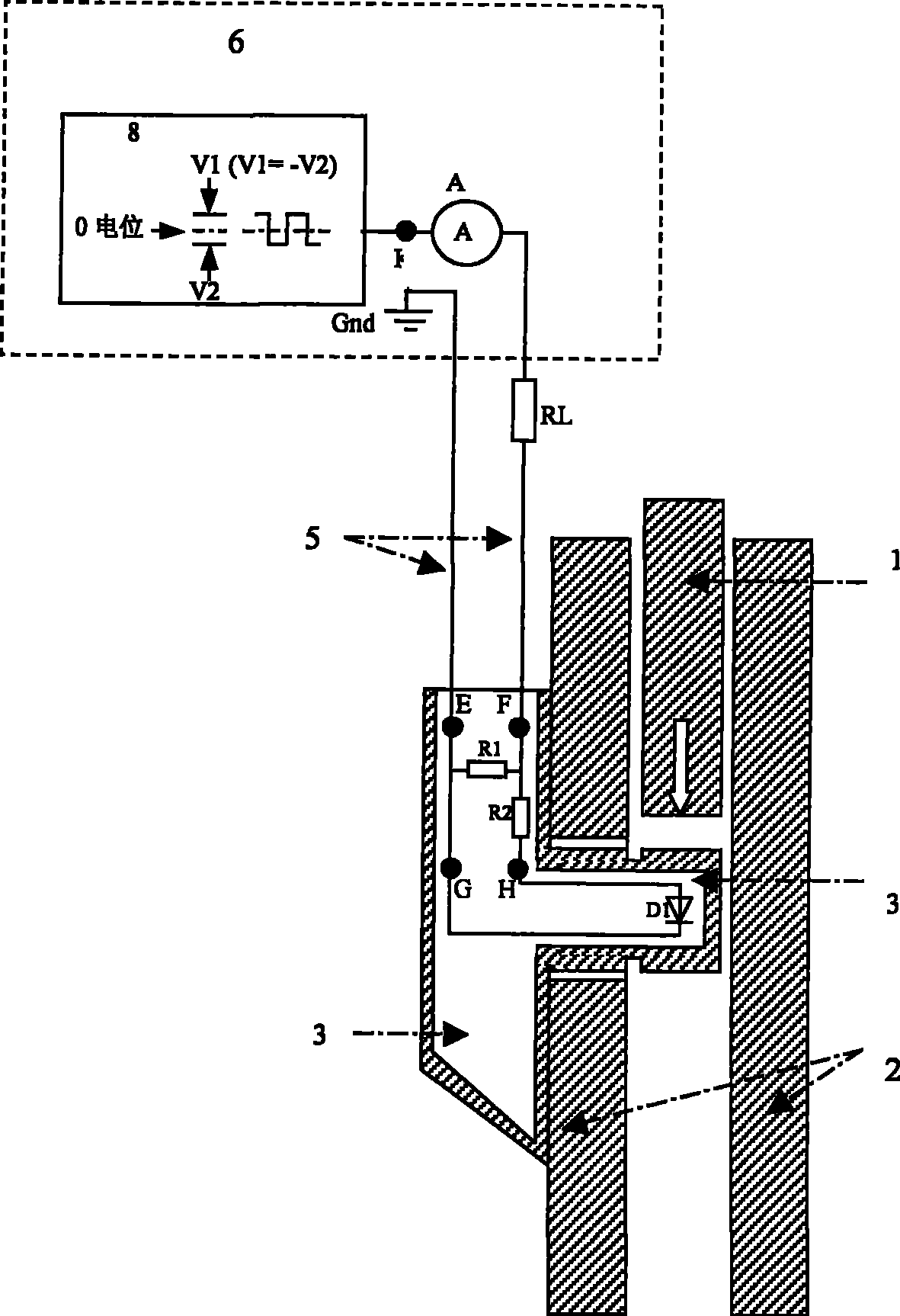
图7.1是钢板桩互锁状态检测传感器的结构及使用示意图。 Figure 7.1 is a schematic diagram of the structure and use of the steel sheet pile interlock state detection sensor. the
图7.2是钢板桩互锁状态检测传感器的使用示意图。 Figure 7.2 is a schematic diagram of the use of the steel sheet pile interlock state detection sensor. the
图8是当传感器及导线完好时电路原理示意图。 Fig. 8 is a schematic diagram of the circuit principle when the sensor and the wire are in good condition. the
图9是当传感器上的探头被剪掉即二极管D1被剪掉,且H、G两裸露触点未短路时原理示意图。 Fig. 9 is a schematic diagram of the principle when the probe on the sensor is cut off, that is, the diode D1 is cut off, and the two exposed contacts of H and G are not short-circuited. the
图10是当传感器上的探头被剪掉即二极管D1被剪掉,且H、G两裸露触点被短路时原理示意图。 Fig. 10 is a schematic diagram of the principle when the probe on the sensor is cut off, that is, the diode D1 is cut off, and the two exposed contacts of H and G are short-circuited. the
图11是当传感器上的探头被剪掉即二极管D1被剪掉,且H、G两裸露触点被接入一等效阻抗为RN的外界导电介质原理示意图。 Figure 11 is a schematic diagram of the principle of an external conductive medium with an equivalent impedance of R N when the probe on the sensor is cut off, that is, the diode D1 is cut off, and the two exposed contacts of H and G are connected to an external conductive medium with an equivalent impedance of R N.
图12是当传感器与地上监测单元连接的两根传输导线被短路时原理示意图。 Fig. 12 is a schematic diagram of the principle when the two transmission wires connecting the sensor to the ground monitoring unit are short-circuited. the
图13是当传感器与地上监测单元连接的两根传输导线被断路时原理示意图。 Fig. 13 is a schematic diagram of the principle when the two transmission wires connecting the sensor to the ground monitoring unit are disconnected. the
图中:RL导线等效电阻,RN外界导电介质等效阻抗,A电流表,1、第二根钢板桩的互锁装置,2、传感器所在钢板桩的互锁装置,3、传感器,4、传感器探头,5、连接地上监测单元和传感器的两根导线,6、地上监测单元,7传感器内部,8、方波信号发生器。In the figure: RL wire equivalent resistance, RN external conductive medium equivalent impedance, A ammeter, 1. Interlocking device of the second steel sheet pile, 2. Interlocking device of the steel sheet pile where the sensor is located, 3. Sensor, 4. Sensor Probe, 5, two wires connecting the ground monitoring unit and the sensor, 6, the ground monitoring unit, 7 inside the sensor, 8, a square wave signal generator.
具体实施方式Detailed ways
如图7.1所示的一种钢板桩互锁状态检测传感器,由二极管D1混联第一电阻R1和第二电阻R2形成闭合回路,从第一电阻R1的两端作为传感器的两个检测端,一个E端,一个F端。 As shown in Figure 7.1, a steel sheet pile interlocking state detection sensor consists of a diode D1 in parallel with the first resistor R1 and the second resistor R2 to form a closed loop, and the two ends of the first resistor R1 are used as the two detection terminals of the sensor. One E end, one F end. the
两根信号线分别由传感器内的E端、F端两点联通到陆地上的监测单元;两根信号线一根经由连接线联到监测单元的信号地---零电位,另一根信号线经由连接线接收到监测单元内信号发生器发出的周期为T秒的电平变化信号例如说明书中指出的方波信号,使单向导电元件二极管(D1)发生周期性的导通和截止;从而使探头内电路到地上的监测单元的信号发生器形成了闭合回路。 The two signal lines are respectively connected to the monitoring unit on the land from the E terminal and the F terminal in the sensor; one of the two signal lines is connected to the signal ground of the monitoring unit --- zero potential through the connection line, and the other is the signal ground. The line receives a level change signal with a period of T seconds from the signal generator in the monitoring unit via the connection line, such as the square wave signal pointed out in the manual, so that the unidirectional conductive element diode (D1) is periodically turned on and off; Thus, a closed loop is formed between the circuit in the probe and the signal generator of the monitoring unit on the ground. the
如图7.1所示传感器探头被安装到钢板桩互锁装置内,二极管D1在探头内,两根信号线分别由传感器内的E、F两点(如图7.1)引出穿过板桩上的护线铁管联通到陆地上的监测单元。两根信号线一根经由连接线联到监测单元的信号地(零电位),另一根信号线经由连接线接收到监测单元内信号发生器发出的周期为T秒的方波信号(但不限于方波信号,电平变化信号即可),信号高低电平分别为V1(正电压)和V2(负电压),且电压值V1=—V2,则其绝对值|V1|=|V2|。从而使探头到地上的监测单元的信号发生器形成了闭合回路(如图7.1和图7.2)。 As shown in Figure 7.1, the sensor probe is installed in the interlocking device of the steel sheet pile, and the diode D1 is inside the probe. The line iron pipe is connected to the monitoring unit on land. One of the two signal lines is connected to the signal ground (zero potential) of the monitoring unit via the connection line, and the other signal line receives the square wave signal with a period of T seconds from the signal generator in the monitoring unit through the connection line (but not Limited to square wave signals, level change signals are enough), the high and low levels of the signal are V1 (positive voltage) and V2 (negative voltage), and the voltage value V1=-V2, then its absolute value |V1|=|V2| . Thus, the signal generator of the monitoring unit from the probe to the ground forms a closed loop (as shown in Figure 7.1 and Figure 7.2). the
当传感器及导线完好时,电路原理(如图8)。当K点电压为V1(正电压)时,电流表测得电流值I3。 When the sensor and wires are intact, the circuit principle (as shown in Figure 8). When the voltage at point K is V1 (positive voltage), the ammeter measures the current value I 3 .
上式中RD是二极管D1的等效电阻。当K点电压为V2(负电压)时,二极管受反向电压而截止,则电流表测得电流值I4,可见I3>I4。 In the above formula, R D is the equivalent resistance of diode D1. When the voltage at point K is V2 (negative voltage), the diode is cut off by the reverse voltage, and the current value I 4 is measured by the ammeter, which shows that I 3 >I 4 .
则传感器及导线完好时,由于K点方波信号周期T秒,所以电流表所测得电流值每隔T/2秒在I3和I4间交替变换一次。 When the sensor and the wire are in good condition, the current value measured by the ammeter alternates between I 3 and I 4 every T/2 seconds because the square wave signal at point K has a period of T seconds.
当传感器上的探头被剪掉即二极管D1被剪掉,且H、G两裸露触点未短路时(如图9),电流表测得电流值I4。When the probe on the sensor is cut off, that is, the diode D1 is cut off, and the two exposed contacts of H and G are not short-circuited (as shown in Figure 9), the ammeter measures the current value I 4 .
当传感器上的探头被剪掉即二极管D1被剪掉,且H、G两裸露触点被短路时(如图10),电流表测得电流值I2,可见I2>I3>I4。 When the probe on the sensor is cut off, that is, the diode D1 is cut off, and the two exposed contacts of H and G are short-circuited (as shown in Figure 10), the ammeter measures the current value I 2 , and it can be seen that I 2 >I 3 >I 4 .
当传感器上的探头被剪掉即二极管D1被剪掉,且H、G两裸露触点被接入一等效阻抗为RN的外界导电介质(如图11),电流表测得电流值IN,可见I2>IN>I4。 When the probe on the sensor is cut off, that is, the diode D1 is cut off, and the two exposed contacts of H and G are connected to an external conductive medium with an equivalent impedance of R N (as shown in Figure 11), the current value I N measured by the ammeter , it can be seen that I 2 >I N >I 4 .
当传感器与地上监测单元连接的两根传输导线被短路时(如图12),电流表测得电流值I1,可见I1>I2>I3>I4。 When the two transmission wires connecting the sensor and the ground monitoring unit are short-circuited (as shown in Figure 12), the ammeter measures the current value I 1 , and it can be seen that I 1 >I 2 >I 3 >I 4 .
当传感器与地上监测单元连接的两根传输导线被断路时(如图13),电流表测得电流值I5,可见I1>I2>I3>I4>I5。 When the two transmission wires connecting the sensor and the ground monitoring unit are disconnected (as shown in Figure 13), the ammeter measures the current value I 5 , and it can be seen that I 1 >I 2 >I 3 >I 4 >I 5 .
I5≈0A I 5 ≈0A
在地上监测单元内设置四个电流参考值Ia、Ib、Ic、Id,使得Ia>I1>Ib>I2>I3>Ic>I4>Id>I5。 Set four current reference values I a , I b , I c , I d in the ground monitoring unit so that I a >I 1 >I b >I 2 >I 3 >I c >I 4 >I d >I 5 .
当电流表所测的电流值恒为IX且满足Ia>IX>Ib时,地上监测单元指示为状态1,表明传感器与地上监测单元连接的两根传输导线已被短路。 When the current value measured by the ammeter is always I X and satisfies I a > I X > I b , the ground monitoring unit indicates
当电流表所测的电流值恒为IX且满足Ib>IX>Ic时,地上监测单元指示为状态2,表明传感器上的探头已被剪掉即二极管D1被剪掉,且H、G两裸露触点被短路。 When the current value measured by the ammeter is always I X and satisfies I b >I X >I c , the ground monitoring unit indicates
当电流表所测的电流值恒为IX且满足Ic>IX>Id时,地上监测单元指示为状态3,表明传感器上的探头已被剪掉即二极管D1被剪掉,且H、G两裸露触点开路。 When the current value measured by the ammeter is always I X and satisfies I c > I X > I d , the ground monitoring unit indicates
当电流表所测的电流值恒为IX且满足Id>IX时,地上监测单元指示为状态 4,表明传感器与地上监测单元连接的两根传输导线被断路。 When the current value measured by the ammeter is always IX and satisfies Id > IX , the ground monitoring unit indicates state 4, indicating that the two transmission wires connecting the sensor and the ground monitoring unit are disconnected.
当电流表所测的电流值每隔T/2秒在IX和IY间交替变换一次,且满足Ib>IX>Ic>IY>Id时,地上监测单元指示为状态5,表明传感器及导线完好。 When the current value measured by the ammeter alternates between I X and I Y every T/2 seconds, and satisfies I b >I X >I c >I Y >I d , the ground monitoring unit indicates
当传感器如图8所示正确安装在预定深度的钢板桩互锁装置内,且传感器通过导线与地上监测单元联通形成闭合回路后打入第二根钢板桩,使第二根钢板桩的互锁装置刺入传感器所在的第一根板桩的互锁装置内。当第二根钢板桩互锁装置的头部打入到传感器所在深度时,若此时地上监测单元指示为状态5,则说明第二根板桩互锁装置上的凸起部位无法将第一根板桩互锁装置内的探头剪切掉,当第二根板桩打入后闭合回路依然不变,从而证明两板桩在探头所在深度已脱离开。若地上监测单元指示为状态2或状态3,说明第二根钢板桩上的互锁装置在传感器安装深度已刺入第一个板桩互锁装置内从而将上述探头剪掉,这使得二极管D1被剪掉。从而可以验证两板桩在探头所在深度已正确互锁。若地上监测单元指示为状态1或状态4,说明传感器与地上监测单元连接的两根传输导线出现上述故障而无法探明探头状态。 When the sensor is correctly installed in the interlocking device of the steel sheet pile at a predetermined depth as shown in Figure 8, and the sensor is connected with the ground monitoring unit through a wire to form a closed loop, then the second steel sheet pile is driven into the second steel sheet pile, so that the interlocking of the second steel sheet pile The device penetrates into the interlock of the first sheet pile where the sensor is located. When the head of the second sheet pile interlocking device is driven into the depth where the sensor is located, if the ground monitoring unit indicates
当传感器上的探头被剪掉即二极管D1被剪掉,且H、G两裸露触点被接入一等效阻抗为RN的外界导电介质(如图11),电流表测得电流值IN,由于I2>IN>I4,所以Ib>IN>Id,此时地上监测单元指示为状态2或状态3,即两板桩在探头所在深度已正确互锁,由于IN不会发生规则的周期性变化,所以此时不会被误判断为状态5,即探头及导线完好,两板桩在探头所在深度已脱离开。 When the probe on the sensor is cut off, that is, the diode D1 is cut off, and the two exposed contacts of H and G are connected to an external conductive medium with an equivalent impedance of R N (as shown in Figure 11), the current value I N measured by the ammeter , because I 2 >I N >I 4 , so I b >I N >I d , at this time the ground monitoring unit indicates
因此即便在湿润的土壤、盐碱地、含金属矿物质较高的地带、沿海地带及河流沿岸等常见恶劣环境进行钢板桩施工时,本发明的传感器可对预定深度两相邻钢板桩的互锁状态得出较为准确的测量结果,不易将探头剪掉误判断为探头完好。Therefore, even when steel sheet piles are constructed in common harsh environments such as wet soil, saline-alkali land, areas with high metal minerals, coastal areas, and river banks, the sensor of the present invention can detect the interlocking state of two adjacent steel sheet piles at a predetermined depth. Obtain more accurate measurement results, and it is not easy to cut off the probe and mistakenly judge that the probe is intact.
Claims (2)
Priority Applications (1)
| Application Number | Priority Date | Filing Date | Title |
|---|---|---|---|
| CN2008100541505A CN101514552B (en) | 2008-10-22 | 2008-10-22 | Sensor for detecting interlocking state of steel sheet piles |
Applications Claiming Priority (1)
| Application Number | Priority Date | Filing Date | Title |
|---|---|---|---|
| CN2008100541505A CN101514552B (en) | 2008-10-22 | 2008-10-22 | Sensor for detecting interlocking state of steel sheet piles |
Publications (2)
| Publication Number | Publication Date |
|---|---|
| CN101514552A CN101514552A (en) | 2009-08-26 |
| CN101514552B true CN101514552B (en) | 2010-12-29 |
Family
ID=41039160
Family Applications (1)
| Application Number | Title | Priority Date | Filing Date |
|---|---|---|---|
| CN2008100541505A Active CN101514552B (en) | 2008-10-22 | 2008-10-22 | Sensor for detecting interlocking state of steel sheet piles |
Country Status (1)
| Country | Link |
|---|---|
| CN (1) | CN101514552B (en) |
Families Citing this family (1)
| Publication number | Priority date | Publication date | Assignee | Title |
|---|---|---|---|---|
| CN105223489A (en) * | 2015-09-01 | 2016-01-06 | 沈阳拓荆科技有限公司 | A kind of interlock circuit testing apparatus and method of testing |
Citations (2)
| Publication number | Priority date | Publication date | Assignee | Title |
|---|---|---|---|---|
| EP0141463A2 (en) * | 1983-10-25 | 1985-05-15 | Hollandsche Beton Groep N.V. | Sheet pile with signalling device |
| FR2646188A1 (en) * | 1989-04-24 | 1990-10-26 | Soletanche | Method for monitoring the engagement of sealing membranes and sealing membranes for the implementation of this method |
-
2008
- 2008-10-22 CN CN2008100541505A patent/CN101514552B/en active Active
Patent Citations (2)
| Publication number | Priority date | Publication date | Assignee | Title |
|---|---|---|---|---|
| EP0141463A2 (en) * | 1983-10-25 | 1985-05-15 | Hollandsche Beton Groep N.V. | Sheet pile with signalling device |
| FR2646188A1 (en) * | 1989-04-24 | 1990-10-26 | Soletanche | Method for monitoring the engagement of sealing membranes and sealing membranes for the implementation of this method |
Also Published As
| Publication number | Publication date |
|---|---|
| CN101514552A (en) | 2009-08-26 |
Similar Documents
| Publication | Publication Date | Title |
|---|---|---|
| US8508234B2 (en) | Method and device for detecting failures in inductive conductivity measurements of a fluid medium | |
| Harvey et al. | Locating groundwater discharge in large lakes using bottom sediment electrical conductivity mapping | |
| CN109324241B (en) | Corrosion diagnosis and early warning method and system for substation grounding grid | |
| CN209656904U (en) | A kind of induced polarization device detecting heavy metal containing sewage | |
| CN101514552B (en) | Sensor for detecting interlocking state of steel sheet piles | |
| CN113913833B (en) | Device, method and circuit for detecting cathode protection effect of buried steel pipeline | |
| CN202255546U (en) | Sensor based on liquid impedance measurement liquid level | |
| CN201440087U (en) | High security liquid level sensor | |
| CN201438127U (en) | Precise liquid level sensor | |
| Dewangan et al. | A correlation between EC and TDS in water: A review | |
| CN2708312Y (en) | A low-frequency eddy current casing damage detector for oil pipes | |
| CN110007351A (en) | A kind of induced polarization method detecting heavy metal containing sewage | |
| JP3679708B2 (en) | Measuring medium flow measurement device | |
| CN108981560B (en) | A detection device for embedment depth of an anti-seepage membrane in a dam and a method of using the same | |
| CN101710149B (en) | System for measuring current density of oil gas pipeline | |
| CN206248166U (en) | A kind of water-level measuring post of portable type measuring level of ground water | |
| CN105158626A (en) | Signal detection circuit for ocean engineering equipment | |
| CN109870214A (en) | Water quantity detection structure and household electrical appliance | |
| CN102621191B (en) | Electrical measurement method and device for detecting high polymer cutoff wall | |
| CN103529478B (en) | Underground pollution group detection system and method | |
| CN115096527B (en) | An electrical signal device for monitoring river embankment leakage | |
| CN216274378U (en) | Cathodic protection monitoring and detecting test pile | |
| CN100565225C (en) | A kind of with a single hole or the long method of contrast resistivity method measurement stake | |
| CN115077597B (en) | Intelligent monitoring device for automatic monitoring, detection and early warning of underground water | |
| KR102808847B1 (en) | Soil sample collecting device and method for monitoring soil using thereof |
Legal Events
| Date | Code | Title | Description |
|---|---|---|---|
| C06 | Publication | ||
| PB01 | Publication | ||
| C10 | Entry into substantive examination | ||
| SE01 | Entry into force of request for substantive examination | ||
| C14 | Grant of patent or utility model | ||
| GR01 | Patent grant | ||
| ASS | Succession or assignment of patent right |
Owner name: CCCC FIRST HARBOR ENGINEERING CO., LTD. NO. 5 ENGI Free format text: FORMER OWNER: CCCC FIRST HARBOR ENGINEERING CO., LTD. |
|
| C41 | Transfer of patent application or patent right or utility model | ||
| TR01 | Transfer of patent right |
Effective date of registration: 20110519 Address after: 300222 Dagu South Road, Tianjin, No. 1002, No. Co-patentee after: CCCC First Harbor Engineering Co., Ltd. Patentee after: Tianjin Port Engineering Institute Ltd. of CCCC First Harbor Engineering Co., Ltd. Co-patentee after: No.1 Engineering Compay Ltd of CCCC First Barbor Engineering Company Ltd. Address before: 300222 Dagu South Road, Tianjin, No. 1002, No. Co-patentee before: CCCC First Harbor Engineering Co., Ltd. Patentee before: Tianjin Port Engineering Institute Ltd. of CCCC First Harbor Engineering Co., Ltd. |