CN101441316B - Zoom lens and image projection apparatus having the same - Google Patents
Zoom lens and image projection apparatus having the same Download PDFInfo
- Publication number
- CN101441316B CN101441316B CN2008101463471A CN200810146347A CN101441316B CN 101441316 B CN101441316 B CN 101441316B CN 2008101463471 A CN2008101463471 A CN 2008101463471A CN 200810146347 A CN200810146347 A CN 200810146347A CN 101441316 B CN101441316 B CN 101441316B
- Authority
- CN
- China
- Prior art keywords
- lens
- lens unit
- light
- zoom
- refracting power
- Prior art date
- Legal status (The legal status is an assumption and is not a legal conclusion. Google has not performed a legal analysis and makes no representation as to the accuracy of the status listed.)
- Expired - Fee Related
Links
Images


Classifications
-
- G—PHYSICS
- G02—OPTICS
- G02B—OPTICAL ELEMENTS, SYSTEMS OR APPARATUS
- G02B15/00—Optical objectives with means for varying the magnification
- G02B15/14—Optical objectives with means for varying the magnification by axial movement of one or more lenses or groups of lenses relative to the image plane for continuously varying the equivalent focal length of the objective
- G02B15/145—Optical objectives with means for varying the magnification by axial movement of one or more lenses or groups of lenses relative to the image plane for continuously varying the equivalent focal length of the objective having five groups only
- G02B15/1455—Optical objectives with means for varying the magnification by axial movement of one or more lenses or groups of lenses relative to the image plane for continuously varying the equivalent focal length of the objective having five groups only the first group being negative
- G02B15/145531—Optical objectives with means for varying the magnification by axial movement of one or more lenses or groups of lenses relative to the image plane for continuously varying the equivalent focal length of the objective having five groups only the first group being negative arranged -++++
-
- G—PHYSICS
- G02—OPTICS
- G02B—OPTICAL ELEMENTS, SYSTEMS OR APPARATUS
- G02B15/00—Optical objectives with means for varying the magnification
- G02B15/14—Optical objectives with means for varying the magnification by axial movement of one or more lenses or groups of lenses relative to the image plane for continuously varying the equivalent focal length of the objective
- G02B15/146—Optical objectives with means for varying the magnification by axial movement of one or more lenses or groups of lenses relative to the image plane for continuously varying the equivalent focal length of the objective having more than five groups
- G02B15/1465—Optical objectives with means for varying the magnification by axial movement of one or more lenses or groups of lenses relative to the image plane for continuously varying the equivalent focal length of the objective having more than five groups the first group being negative
Abstract
The present invention provides a zoom lens and image projection apparatus having the same. The zoom lens comprises a plurality of lens units including a first lens unit disposed most adjacent to an enlargement side and having negative refractive power, wherein one or more lens units of the plurality of lens units are moved in the direction of the optical axis thereof during magnification change, and wherein the first lens unit includes a 1-1st lens unit comprising at least one lens of negative refractive power and moved during focusing and a 1-2nd lens unit having positive refractive power, and fixed during focusing.
Description
Present patent application be priority date be on February 22nd, 2005, national applications number be 200610004104.5, denomination of invention divides an application for the application for a patent for invention of " zoom lens and have the image projection device of these zoom lens ", it all is incorporated herein by reference at this.
Technical field
The present invention relates to zoom lens and have the image projection device of these zoom lens, and be suitable for having for example long back focal length and the liquid crystal projection apparatus that all has higher optical property in each projection enlargement factor.
Background technology
So far, the display element that has proposed various uses such as liquid crystal display cells is with will be at the liquid crystal projection apparatus (image projection device) of the image projection that forms on the display element on the screen surface.
Various characteristics cited below need be for the projecting lens of these liquid crystal projection apparatus uses.
Usually, in the color liquid crystal projection of the three element type of using three liquid crystal display cells, light from white light source is separated into redness, green and blue by color separation optical system, these coloramas are directed into each liquid crystal display cells, and the light that manifests from these liquid crystal display cells is made up and incides on the projecting lens by color combination optical system.
In this projection, projecting lens must have the back focal length of a certain constant length, to provide spacing between each liquid crystal display cells and projecting lens, is used for being provided for betwixt making up prism through the colorama behind the liquid crystal display cells etc.
If incide the angle of the light beam on the color combination optical system changes from liquid crystal display cells, the spectral-transmission favtor of color combination optical system changes thereupon so, and the brightness that is projected each color in the image depends on the visual angle and is changed, and image becomes the image that is difficult to see.Therefore, in order to reduce influence for the dependence of angle, color combination optical system must be so-called telecentric optical system, and the pupil of the liquid crystal display cells of this telecentric optical system (dwindling conjugate plane (reduction conjugate surface)) side is basically at unlimited distance.
When the picture (image) of the liquid crystal display cells of three kinds of colors was combined and is projected on the screen, each color pixel must be overlapped on the whole zone of screen, makes that the high resolving power sense can be by destructions such as for example dual character display.
Therefore, must in visible region, proofread and correct the color misregistration (misregistration) (aberration of enlargement factor) that in projecting lens, occurs well.
Distortion must fine being corrected, and makes that being projected image can not take place to distort and can not be difficult to see.
Projecting lens is necessary for the bright projecting lens of little Fno (F number), introducing light from light source effectively.
Necessary compact conformation of projector, weight of carrying compact liquid crystal panel is lighter on it, with outstanding portability and mobility.
Must be projected image what various projector distances obtained, that is, the aberration fluctuation in the zoom process must be less.
As the zoom lens that can satisfy these requirements, a kind of like this zoom lens that are used for projector are arranged, and the focusing of these zoom lens only realizes (Japanese Patent Application Publication No.H10-186235, U.S. Patent No. 6580564 and Japanese Patent Application Publication No.2004-226803) by some optical elements in the lens unit that moves.
Japanese Patent Application Publication No.H10-186235 discloses a kind of five unit zoom lens, these Unit five zoom lens comprise the lens unit of negative, positive, positive and negative and positive refracting power successively from screen side, wherein, rearmost (the being projected image-side) positive lens that comprises first lens unit of four positive and negative, negative, positive lens is fixed and three lens of screen side are moved, and focuses on realizing thus.
U.S. Patent No. 6580564 and Japanese Patent Application Publication No.2004-226803 disclose a kind of five unit zoom lens, these Unit five zoom lens comprise the lens unit of negative, positive, positive and negative and positive refracting power successively from screen side, wherein, first lens unit is made of two lens elements with negative refracting power, and the interval between these lens elements is changed, to realize focusing thus.The both makes positive lens involved in concentrating element and the refracting power of the whole concentrating element that weakens.
And, as the projecting lens that is used for liquid crystal projection apparatus, six unit zoom lens have been proposed, these Unit six zoom lens are from amplifying the conjugation side (here, this term is used interchangeably with the meaning identical with front side and Zoom Side) comprise successively by negative, positive, positive and negative, just (or negative) and six lens units forming as a whole of the configuration of first to the 6th lens unit of refracting power just, wherein, their predetermined lens unit is suitably moved, to realize zoom (U.S.'s publication US2001-050818 number) thus.
In these Unit six zoom lens, in the zoom process from the wide-angle side to the telescope end, for can all being moved to, therebetween second to the 5th lens unit dwindles the conjugation side (here, this term is used interchangeably with the meaning identical with rear side and reduced side), it is constant that the length overall of lens keeps in the process of zoom.And these zoom lens are distortion in the zoom process and aberration is reduced and dwindling the zoom lens that the conjugation side has disposition far away.Disclosing in US2001-050818 number disclosed configuration of this U.S.'s publication: positive and negative and negative lens constitutes first lens unit by three from amplifying the conjugation side, and this first lens unit is driven, to realize focusing thus.
Usually, as the method that when realizing focusing on, suppresses the fluctuation of various aberrations, there are refracting power that adds the strong focusing lens unit as much as possible and the method that reduces the amount of movement of condenser lens to greatest extent.In above-mentioned Japanese Patent Application Publication No.H10-186235, U.S. Patent No. 6580564 and Japanese Patent Application Publication No.2004-226803, in the lens arrangement of first lens unit, the condenser lens unit not only is made of negative lens, therefore, the tendency that has the refracting power of condenser lens unit to die down, and in the focusing process its moves the big and fluctuations various aberrations of quantitative change and becomes big.
And, lens arrangement for the zoom lens that are used for projector, the fact usually is, in order to obtain long back focal length (back focus), it is made into back focusing (retrofocus) type, and, having disposition far away in order to make reduced side, the lens unit with stronger positive refracting power is set at reduced side.
But the zoom lens of this structure have a kind of like this tendency, that is, for example since the aberration of blue enlargement factor than green more by (direction of optical axis) down, the asymmetry increase of overall lens system.
And it is few more that the quantity of lens becomes, and it is many more that the refracting power of each lens increases, and therefore, particularly the position more becomes near the negative lens of reduced side than diaphragm and is easy to cause along whole direction the aberration of the enlargement factor of high-order.And it is big more that zoom ratio becomes, and it is big more that the fluctuation of the aberration of the enlargement factor from the wide-angle side to the telescope end also is tending towards becoming.
Summary of the invention
The objective of the invention is to, a kind of zoom lens (zoom lens) that are applicable in the liquid crystal projection apparatus for example are provided, these zoom lens are realized the miniaturization of whole lens combination and are proofreaied and correct the various aberrations that caused by focusing well, and have the good optical performance on whole projector distance.
Another object of the present invention is to, a kind of zoom lens that are applicable in the projector are provided, these zoom lens are proofreaied and correct the aberration of enlargement factor well and can easily be obtained higher optical property.
Zoom lens of the present invention comprise:
Comprise on the position that is set at the most contiguous Zoom Side and have a plurality of lens units of first lens unit of negative refracting power,
At least one of a plurality of lens units that in the process that enlargement factor changes, are moved along its optical axis direction;
Described first lens unit comprises:
Comprise at least one lens with negative refracting power and the 1-1 lens unit that in the focusing process, is moved; With
The 1-2 lens unit that has positive refracting power and in the focusing process, be fixed.
Zoom lens of the present invention comprise:
Be set on the position of the most contiguous Zoom Side and have first lens unit of negative refracting power;
Be set on the position of the most contiguous reduced side and have the last lens unit of positive refracting power; With
One or more lens unit that in the process of zoom (enlargement factor variation), moves along its optical axis direction;
Wherein, meet the following conditions:
32<υdR-υdF,
Here, υ dF represents to make Abbe (Abbe) number of the material of first lens in locational first lens unit that is set at the most contiguous Zoom Side, these first lens have negative refracting power, υ dR represents to make the Abbe number of the material of the last lens in the locational last lens unit that is set at the most contiguous reduced side, and these last lens have positive refracting power.
Description of drawings
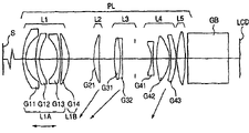
Fig. 1 is to use the synoptic diagram according to the essential part of the image projection device of the zoom lens of embodiment 1.
Fig. 2 represents the aberration according to the wide-angle side of the zoom lens of numerical value embodiment 1.
Fig. 3 represents the aberration according to the telescope end of the zoom lens of numerical value embodiment 1.
Fig. 4 A and Fig. 4 B represent the aberration according to the enlargement factor of the zoom lens of data embodiment 1.
Fig. 5 is to use the synoptic diagram according to the essential part of the image projection device of the zoom lens of embodiment 2.
Fig. 6 represents the aberration according to the wide-angle side of the zoom lens of numerical value embodiment 2.
Fig. 7 represents the aberration according to the telescope end of the zoom lens of numerical value embodiment 2.
Fig. 8 is to use the synoptic diagram according to the essential part of the image projection device of the zoom lens of embodiment 3.
Fig. 9 represents the aberration according to the wide-angle side of the zoom lens of numerical value embodiment 3.
Figure 10 represents the aberration according to the telescope end of the zoom lens of numerical value embodiment 3.
Figure 11 is used to illustrate the optical system according to the projection type video display device of present embodiment.
Figure 12 is the synoptic diagram of the essential part of color liquid crystal projector.
Embodiment
Below embodiments of the invention can be described.
Zoom lens according to embodiment have a plurality of lens units, these lens units comprise the lens unit GF that is arranged on front side (Zoom Side) and has negative refracting power (focal power), and, one or more other lens unit of a plurality of lens units beyond the lens unit GF moves realizing zoom thus along the direction of its optical axis, and the visual information projection that will be arranged on rear side (reduced side) is to predetermined surface.At this moment, lens unit GF is characterised in that and is included in the lens unit A with negative refracting power (refractive power) mobile in the focusing process and Immobile lens unit B with positive refracting power in the focusing process.Here, lens unit is not only represented a plurality of lens, and single lens are also referred to as lens unit.
At this moment, lens unit A only is made of the lens of negative refracting power.
Therefore, in the focusing process, have only the lens in first lens unit to be moved to increase the refracting power of concentrating element thus with negative refracting power, and the amount of movement of minimizing condenser lens unit, and the fluctuation of various aberrations is minimized, reduce thus because the variation of the optical property that the difference of projector distance causes.
Zoom lens according to another embodiment have a plurality of lens units, these lens units comprise and are set at front side and have the lens unit GF of negative refracting power (focal power) and be set at rear side and have the lens unit GR of positive refracting power (focal power), and one or more other lens unit of a plurality of lens units beyond lens unit GF and the lens unit GR moves along the direction of its optical axis, realizing zoom thus, and the visual information projection that will be arranged on rear side is to predetermined surface.At this moment, the lens GFa of the front side of lens unit GF has negative refracting power, and the lens GRb of the rear side of lens unit GR has positive refracting power, and these zoom lens are characterised in that and satisfy condition
32<υdR-υdF...(1)
Here, υ dF and υ dR represent to make Abbe (Abbe) number of the material of lens GFa and lens GRb respectively.
And under these structural conditions, lens combination GF is characterised in that, is made of the lens unit B of lens unit A with negative refracting power that is moved in the focusing process and the positive refracting power that is fixed in the focusing process successively from the front side to rear side.
And lens unit A only is made of the lens with negative refracting power.
As mentioned above, lens GFa and lens GRb are constituted as feasible, the Abbe of its material (Abbe) the number expression formula (1) that can satisfy condition, and thus, the aberration of enlargement factor is proofreaied and correct well.
Particularly, by the expression formula that satisfies condition (1), even in the zoom lens of big zoom ratio, the fluctuation of the aberration of enlargement factor is also proofreaied and correct well by the lens of negligible amounts.
Use the material of high-dispersion glass, use the material of low dispersion as the lens GRb of rear side as the lens GFa of front side.In the lens GFa of front side, the variation of the height of incidence of the light of hi-vision height becomes from the wide-angle side to the telescope end greatly, and therefore, the aberration of the enlargement factor of the high-order of Chu Xianing produces manyly in wide-angle side below, and produces fewly at telescope end.At this moment, conditional expression (1) is satisfied, thus, can produce along the aberration of the enlargement factor of the high-order of following direction, eliminating according to the zoom situation along the aberration of the enlargement factor of the high-order of top direction, and the suitable aberration of enlargement factor is by the formation lens correction of negligible amounts.
At this moment, the higher limit of conditional expression (1) is set preferably, to satisfy condition
υdR-υdF<50...(1a)
Thus, be easy to whole projector distances are proofreaied and correct preferably the aberration of enlargement factor.
And, have disposition far away in order to make rear side, preferably satisfy condition
7.0<| DP/fw|... (2) here, DP represents that from position that the image information of rear side (reduced side conjugate position) is set up to the distance of emergent pupil (pupil), fw represents the focal length of total system in wide-angle side.More preferably the value of conditional expression (2) is greater than 10.0.And, wishing | DP/fw| is 100 or littler, and it is preferably less than 20.
If do not satisfy conditional expression (2), disposition (telecentricity) variation far away, the brightness of each color dissimilates with the visual angle when the present invention is used to color projecting apparatus, and is bad like this.
In each embodiment, constitute each element as mentioned above, realizing being applicable to the zoom lens of projector thus, the fluctuation of the aberration of the enlargement factor in the very little and zoom process of the fluctuation of the aberration that is caused by focusing of these zoom lens is also very little.
And, any one and the display unit that is used to form original image that have above-mentioned zoom lens according to the image projection device of present embodiment, and will project to screen surface (projecting plane by the original image that display unit forms by above-mentioned zoom lens, certainly, under the situation of rear-projection type, be preferably have biconvex lens etc. and have the image planes or the screen surface of the effect of scatter incident light) on.
The accompanying drawing of present embodiment is represented in simple declaration now.
Fig. 1 is to use the synoptic diagram according to the essential part of the image projection device of the zoom lens of embodiment 1 (liquid crystal video projector).Fig. 2 and Fig. 3 are illustrated respectively in the aberration of object distance (from the distance of first lens unit) for wide-angle side under the situation of 1.7m (short focal length side) and telescope end (long-focus side), and the numerical value of the following numerical value embodiment 1 corresponding with embodiments of the invention 1 is represented by the mm of unit.
Fig. 4 A and Fig. 4 B represent respectively when object distance is 1.7m, at the aberration with respect to the enlargement factor of the wavelength 610nm (red) of wavelength 550nm and wavelength 470nm (indigo plant) wide-angle side of each picture altitude Y and telescope end, numerical value embodiment 1.
Fig. 5 is to use the synoptic diagram according to the essential part of the image projection device of the zoom lens of embodiment 2.Fig. 6 and Fig. 7 are illustrated respectively in the aberration of wide-angle side under the situation that object distance is 1.7m (short focal length side) and telescope end (long-focus side), and the numerical value of the following numerical value embodiment 2 corresponding with embodiments of the invention 2 is represented by the mm of unit.
Fig. 8 is to use the synoptic diagram according to the essential part of the image projection device of the zoom lens of embodiment 3.Fig. 9 and Figure 10 are illustrated respectively in the aberration of wide-angle side under the situation that object distance is 1.7m (short focal length side) and telescope end (long-focus side), and the numerical value of the following numerical value embodiment 3 corresponding with embodiments of the invention 3 is represented by the mm of unit.
Fig. 1, Fig. 5 and Fig. 8 represent the image projection device according to embodiment 1~3, and wherein, the original image on the LCD (being projected image) is exaggerated, and are projected on the screen surface S by the use of zoom lens (projecting lens) PL.
Letter S represents screen surface (projection surface), and LCD represents the original image (being projected image) of liquid crystal panel (liquid crystal display cells) etc.Screen surface S and original image LCD have mutual yoke relation mutually, usually, screen surface S is corresponding to the Zoom Side (forward) of the conjugate points (first conjugate points) of longer distance, and original image LCD is corresponding to the reduced side (backward) of more short-range conjugate points (second conjugate points).When zoom lens were used as camera chain, screen surface S side was corresponding to the thing side, and original image LCD side is corresponding to the picture side.
GB is expressed as color combination prism or polarizing filter and color filter etc. and correspondingly is arranged on glass blocks (prism) in the optical design.
Zoom lens PL is installed on the liquid crystal video projector main body (not shown) by the link (not shown).Be included in the liquid crystal display cells LCD side behind the glass blocks GB in the projector main body.
It is several 1.75 to have a F according to the zoom lens of embodiment 1~3, and short projector distance 2.5m (numerical value embodiment is represented by the mm of unit) with visual information projection's to 100 inch type screen surface on.
In Fig. 2, Fig. 3, Fig. 6, Fig. 7, Fig. 8 and Fig. 9, G represents the aberration on the wavelength 550nm, and S (gradient of sagittal image surface) and M (gradient of meridianal image surface) all represent the aberration on the wavelength 550nm.Fno is the F number.W is a half angle of view, and Y is picture altitude (being projected the picture altitude of side).
Describe zoom lens now in detail according to each embodiment.
In the embodiment 1 of Fig. 1, L1 represents to have first lens unit of negative refracting power, L2 represents to have second lens unit of positive refracting power, L3 represents to have the 3rd lens unit of positive refracting power, L4 represents to have the 4th lens unit of negative refracting power, L5 represents to have the 5th lens unit of positive refracting power, and L6 represents to have the 6th lens unit of positive refracting power
The first lens unit L1 has the 1A lens unit L1A of negative refracting power and has the 1B lens unit L1B of positive refracting power.
In embodiment 1, in the zoom from the wide-angle side to the telescope end (amplification) process, as showing, the second lens unit L2, the 3rd lens unit L3, the 4th lens unit L4 and the 5th lens unit L5 are independent to be moved to the first conjugate points side (screen S side) as the Zoom Side as arrow.
The first lens unit L1 and the 6th lens unit L6 do not move for zoom.The 1A lens unit L1A with negative refracting power among the first lens unit L1 moves on its optical axis to realize focusing thus.1B lens unit L1B can not be mobile for focusing on.
Aperture diaphragm (stop) SP is set between the 3rd lens unit L3 and the 4th lens unit L4, and moves with the 3rd lens unit L3 in the zoom process.Be used to prevent that the laminated coating that reflects is set at each lens surface.
In embodiment 1, from the object side to image side, 1A lens unit L1A comprises negative lens G11, two negative lens G12 and negative lens G13 that lens surface is an aspherical shape successively, and 1B lens unit L1B comprises the positive lens G14 that the rear surface is a convex shape.Here, the 1A lens unit is made of three negative lenses, but can or can be made of two, four or more a plurality of negative lens by a negative lens certainly.That is, 1A lens unit L1A can only be made of negative lens.But from aberration that suppresses total system and the angle that reduces the size of total system, it can be by more than or equal to two and constitute smaller or equal to five negative lens, and preferably are made of three or more negative lenses.And the 1B lens unit can be made of two positive lenss.And the lens (optical element) that do not have refracting power (not having focal power) basically can be set on the position than the more contiguous amplification conjugation of 1A lens unit L1A side.Wish to be set at than the focal length of locational these lens of the more contiguous amplification conjugation of 1A lens unit L1A side and be 20 times (preferred 100 times) of the focal length of the zoom lens of its wide-angle side or bigger.
The second lens unit L2 comprises the positive lens G21 that front surface is a convex shape.
The 3rd lens unit L3 comprises the joint lens (cemented lens) of positive lens G31 and negative lens G32.
The negative lens G41 that it is concave that the 4th lens unit L4 comprises two lens surfaces.
Positive lens G51 that it is convex shape that the 5th lens unit L5 comprises two lens surfaces and rear surface are the positive lens G52 of convex shape.
Two lens surfaces of positive lens G52 are aspherical shape.
The positive lens G61 that it is convex shape that the 6th lens unit L6 comprises two lens surfaces.
Design among the embodiment 1 makes, in the focusing process, has only the lens element with negative refracting power among the first lens unit L1 to be moved.Thus, the refracting power of the element that is moved in the focusing process (bearing) becomes bigger than the refracting power of the whole first lens unit L1, and, to compare with focusing on situation about realizing by the whole first lens unit L1, amount of movement can reduce, and therefore, the fluctuation of aberration reduces.And three negative lens G11~G13 that constitute the element that is moved in the focusing process move to the Zoom Side jointly, and therefore, the structure of lens barrel can be easily accomplished.
In embodiment shown in Figure 52, L1 represents to have first lens unit of negative refracting power, L2 represents to have second lens unit of positive refracting power, L3 represents to have the 3rd lens unit of positive refracting power, L4 represents to have the 4th lens unit of negative refracting power, L5 represents to have the 5th lens unit of positive refracting power, and L6 represents to have the 6th lens unit of positive refracting power, and L7 represents to have the 7th lens unit of positive refracting power.
The first lens unit L1 has the 1A lens unit L1A of negative refracting power and has the 1B lens unit L1B of positive refracting power.
In embodiment 2, in the zoom from the wide-angle side to the telescope end (amplification) process, as shown by arrows, the second lens unit L2, the 3rd lens unit L3, the 4th lens unit L4, the 5th lens unit L5 and the 6th lens unit L6 are independent moves to the first conjugate points side (screen S side) as the Zoom Side.Here, the first lens unit L1 also can be moved in the zoom process.Like this too in other embodiments.
The first lens unit L1 and the 7th lens unit L7 do not move for zoom.The 1A lens unit L1A with negative refracting power among the first lens unit L1 moves on its optical axis to realize focusing thus.1B lens unit L1B can not be mobile for focusing on.
Aperture diaphragm SP is set between the 3rd lens unit L3 and the 4th lens unit L4, and moves with the 3rd lens unit L3 in the zoom process.Be used to prevent that the laminated coating that reflects is set at each lens surface.
In embodiment 2, from the object side to image side, 1A lens unit L1A comprises negative lens G11, two negative lens G12 and negative lens G13 that lens surface is an aspherical shape successively, and 1B lens unit L1B comprises the positive lens G14 that the rear surface is a convex shape.Here, the 1A lens unit is made of three negative lenses, but can or can be made of two, four or more a plurality of negative lens by a negative lens certainly.That is, 1A lens unit L1A can only be made of negative lens.But from aberration that suppresses total system and the angle that reduces the size of total system, 1A lens unit L1A is preferably by more than or equal to two and constitute smaller or equal to five negative lens, or preferably is made of three or more negative lenses.And the 1B lens unit can be made of two positive lenss.And the lens (optical element) that do not have refracting power (not having focal power) basically can be set on the position than the more contiguous amplification conjugation of 1A lens unit L1A side.Wish to be set at than the focal length of locational these lens of the more contiguous amplification conjugation of 1A lens unit L1A side and be 20 times (preferred 100 times) of the focal length of the zoom lens of its wide-angle side or bigger.
The second lens unit L2 comprises the positive lens G21 that front surface is a convex shape.The 3rd lens unit L3 comprises the joint lens of positive lens G31 and negative lens G32.The negative lens G41 that it is concave that the 4th lens unit L4 comprises two lens surfaces.The positive lens G51 that it is convex shape that the 5th lens unit L5 comprises two lens surfaces.The 6th lens unit L6 comprises the positive lens G61 that the rear surface is a convex shape.
Two lens surfaces of positive lens G61 are aspherical shape.
The positive lens G71 that it is convex shape that the 7th lens unit L7 comprises two lens surfaces.
In embodiment 2, zoom lens integral body comprises seven lens units, and makes the fluctuation of the aberration in the zoom process become very little.Identical with embodiment 1, the optical effect during focusing is realized by 1A lens unit L1A.
In embodiment shown in Figure 83, L1 represents to have first lens unit of negative refracting power, L2 represents to have second lens unit of positive refracting power, L3 represents to have the 3rd lens unit of positive refracting power, L4 represents to have the 4th lens unit of positive refracting power, and L5 represents to have the 5th lens unit of positive refracting power.The first lens unit L1 has the 1A lens unit L1A of negative refracting power and has the 1B lens unit L1B of positive refracting power.
In embodiment 3, in the zoom from the wide-angle side to the telescope end (amplification) process, as shown by arrows, the second lens unit L2, the 3rd lens unit L3 and the 4th lens unit L4 are independent to be moved to the first conjugate points side (screen S side) as the Zoom Side.
The first lens unit L1 and the 5th lens unit L5 do not move for zoom.The 1A lens unit L1A with negative refracting power among the first lens unit L1 moves on its optical axis to realize focusing thus.1B lens unit L1B can not be mobile for focusing on.
Aperture diaphragm SP is set between the 3rd lens unit L3 and the 4th lens unit L4, and moves with the 3rd lens unit L3 in the zoom process.Be used to prevent that the laminated coating that reflects is set at each lens surface.
In embodiment 3, from the object side to image side, 1A lens unit L1A comprises negative lens G11, two negative lens G12 and negative lens G13 that lens surface is an aspherical shape successively, and 1B lens unit L1B comprises the positive lens G14 that the rear surface is a convex shape.Here, the 1A lens unit is made of three negative lenses, but can or can be made of two, four or more a plurality of negative lens by a negative lens certainly.That is, the 1A lens unit can only be made of negative lens.But from aberration that suppresses total system and the angle that reduces the size of total system, 1A lens unit L1A is preferably by more than or equal to two and constitute smaller or equal to five negative lens, or preferably is made of three or more negative lenses.And the 1B lens unit can be made of two positive lenss.And the lens (optical element) that do not have refracting power (not having focal power) basically can be set on the position than the more contiguous amplification conjugate points of 1A lens unit L1A side.Wish to be set at than the focal length of locational these lens of the more contiguous amplification conjugate points of 1A lens unit L1A side and be 20 times (preferred 100 times) of the focal length of the zoom lens of its wide-angle side or bigger.
The second lens unit L2 comprises the positive lens that front surface is a convex shape.The 3rd lens unit L3 comprises the joint lens of positive lens G31 and negative lens G32.The positive lens G43 that positive lens G42 that the negative lens G41 that it is concave that the 4th lens unit L4 comprises two lens surfaces, two lens surfaces are convex shape and rear surface are convex shape.
Two lens surfaces of positive lens G43 are aspherical shape.
The positive lens G51 that it is convex shape that the 5th lens unit L5 comprises two lens surfaces.
In embodiment 3, zoom lens integral body comprises five lens units, and off-centre is well-behaved to be reduced from spending higher relatively negative lens G41 and the mutual alignment error of positive lens G42.Make the manufacturing of zoom lens become easy thus.Identical with embodiment 1, the optical effect during focusing is realized by 1A lens unit L1A.
Any one projection type video display device as projecting lens (projection optical system) of the zoom lens that use embodiment 1~3 explanation is described referring now to Figure 11.Here, with reference to Figure 11 the optical texture of the projection type video display device of carrying reflection type liquid crystal display element (can by making such as the image formation component of reflective liquid crystal panel or projection type liquid crystal's panel) is described on it, this reflection type liquid crystal display element is made of projecting lens optical system 70 (see figure 1)s in lamp 1, lamp optical system α, color separated and combinative optical system β and the projecting lens lens barrel 5.
In Figure 11, Reference numeral 41 expression emissions have the luminotron of the white light of continuous spectrum, and the direction that Reference numeral 42 expressions are used for being scheduled on the edge is assembled the reflection of light device from luminotron 41, and luminotron 41 and the reverberator 42 common element lamps 1 that form.
Above-mentioned each element constitutes the element of lamp optical system α.
Constitute the element of color separated and combinative optical system β from each parts of dichroic mirror 58 to the 3rd polarization beam splitters 69.
Optical effect is described now.
Assembled along predetermined direction by reverberator 42 from the light of luminotron 41 emissions.The reflecting surface of reverberator 42 has the parabolic surface shape, and becomes the light beam of the axis of symmetry (optical axis) that is parallel to parabolic surface from the light of parabolic surface.But, be not light beam from the light beam of luminotron 41, but luminotron 41 have the luminous component of finite size from the ideal point light source, therefore, the light beam that be assembled also comprises the component of many not parallel with the axis of symmetry of parabolic surface light.
These light beams incide on the first cylindrical-array 43a.The light beam that incides on the first cylindrical-array 43a is divided into a plurality of light beams consistent with each cylindrical lens, and assembled (ribbon beams of a plurality of along continuous straight runs), and near polarized light conversion element 45, form a plurality of light beams (ribbon beams of a plurality of along continuous straight runs) by UVA light filter 44 and via the second cylindrical-array 43b.
Polarized light conversion element 45 comprises a plurality of polarized light release surfaces, reflecting surface and the half-wave plate of vertically configuration, and, a plurality of light beams incide on the capable corresponding polarized light release surface with its place, and are separated into the light of the S polarized component of the light of the P polarized component that sees through and reflection.
The surface reflection that is reflected of the light of S polarized component of reflection, and penetrate along the direction identical with the P polarized component.On the other hand, the light transmission half-wave plate of the P polarized component that sees through, and be converted into the polarized component identical with the S polarized component, and penetrate as the controlled light in polarization direction.After penetrating from polarized light conversion element 45, a plurality of light beams (ribbon beams of a plurality of along continuous straight runs) that are polarized conversion see through preceding compressor reducer 46 by reflective mirror 47 reflections 90 degree, and arrive collector lens 48 and back compressor reducer 49.
Here, the optical effect of preceding compressor reducer 46, collector lens 48 and back compressor reducer 49 suitably is provided with.A plurality of light beams are taked the shape of the mutual crossover of rectangular image, and form the even field of illumination of rectangle.
Reflection type liquid crystal display element 61R, 61G and the 61G that will be described hereinafter are set in this field of illumination.Then, the light that forms the S polarized light by polarized light conversion element 45 incides on the dichroic mirror 58.Dichroic mirror 58 reflected light B (wavelength 430~495nm) and light R (wavelength 590~650nm), and see through light G (wavelength 505~580nm) therein.
The light path of light G is described now.
The light G that sees through dichroic mirror 58 incides on the light incident side polarization plates 59.Light G is still the S polarized light after being separated by dichroic mirror 58.After penetrating from light incident side polarization plates 59, light G incides on first polarization beam splitter 60 as the S polarized light, and is polarized the reflection of light release surface, and arrives the reflection type liquid crystal display element 61G that is used for G.Be used for the reflection type liquid crystal display element 61G of G, light G is by image modulation and reflection.In by the light G of the reflection of image modulation, the S polarized component is again by the polarized light release surface 60a of first polarization beam splitter 60 reflection, and gets back to light source 1 side and removed from projected light.
On the other hand, in by the reflected light of the light G of image modulation, the P polarized component sees through the polarized light release surface 60a of first polarization beam splitter 60, and advances to the 3rd polarization beam splitter 69 as projected light.
At this moment, all be converted in the state (state that black is shown) of S polarized light in all polarized components, the slow axis (slow axis) that is set at first polarization beam splitter 60 and is used for the quarter wave plate 62G between the reflection type liquid crystal display element 61G of G is adjusted to predetermined direction, thus, the vibration effect of polarization state that appears at first polarization beam splitter 60 and be used for the reflection type liquid crystal display element 61G of G can be suppressed to very little level.
The light G that penetrates from first polarization beam splitter 60 incides on the 3rd polarization beam splitter 69 as the P polarized light, and sees through the polarized light release surface 69a of the 3rd polarization beam splitter 69 and arrive projecting lens 70.
On the other hand, light R and the light B that is reflected by dichroic mirror 58 incides on the light incident side polarization plates 64.Light R is still the S polarized light with light B after being separated by dichroic mirror 58.Then, light R and light B penetrate from light incident side polarization plates 64, incide then on the first look selectivity phase difference plate 65.The first look selectivity phase difference plate 65 only has the effect that turn 90 degrees is revolved in the polarization direction of light B, and light R and light B incide on second polarization beam splitter 66 as P polarized light and S polarized light respectively thus.The light R that incides on second polarization beam splitter 66 as the S polarized light is reflected by the polarized light release surface of second polarization beam splitter 66, and arrives the reflection type liquid crystal display element 61R that is used for light R.And the light B that incides on second polarization beam splitter 66 as the P polarized light sees through the polarized light release surface 66a of second polarization beam splitter 66, and arrives the reflection type liquid crystal display element 61B that is used for light B.
Incide light R on the reflection type liquid crystal display element 61R that is used for light R by image modulation and reflection.In by the reflected light of the light R of image modulation, the S polarized component is reflected again by the polarized light release surface 66a of second polarization beam splitter 66, and returns light source 1 side, and is removed from projected light.On the other hand, in by the reflected light of the light R of image modulation, the P polarized component sees through the polarized light release surface 66a of second polarization beam splitter 66, and advances to the second look selectivity phase-plate (phase plate) 67 as projected light.
And, incide light B on the reflection type liquid crystal display element 61B that is used for light B by image modulation and reflection.In by the reflected light of the light B of image modulation, the P polarized component sees through the polarized light release surface 66a of second polarization beam splitter 66 again, and returns light source 1 side, and is removed from projected light.
On the other hand, in by the reflected light of the light B of image modulation, the S polarized component is reflected by the polarized light release surface 66a of second polarization beam splitter 66, and advances to the second look selectivity phase-plate 67 as projected light.
At this moment, be set at second polarization beam splitter 66 and be used for light R and the reflection type liquid crystal display element 61R of light B and quarter wave plate 62R between the 61B and the slow axis of 62B by adjusting respectively, can as the situation of light G, realize the adjustment of demonstration of the black (black) of light R and light B.
The projected light that is combined as light beam and light R that penetrates from second polarization beam splitter 66 and light B thus, light R makes its polarization direction by 67 rotations 90 of the second look selectivity phase-plate, and become the S polarized component, and further analyzed and incide on the 3rd polarization beam splitter 69 by emitting side polarization plates 68.
And light B sees through the second look selectivity phase-plate 67 in good condition as the S polarized light, and is further analyzed by emitting side polarization plates 68, and incides on the 3rd polarization beam splitter 69.Analysis by emitting side polarization plates 68, the projected light of light R and light B becomes the removed light of reactive component, here, reactive component is by passing second polarization beam splitter 66, reflection type liquid crystal display element 61R and 61B and being respectively applied for light R and quarter wave plate 62R and the 62B of light B produce.
Then, the projected light that incides light R on the 3rd polarization beam splitter 69 and light B is by the polarized light release surface 69a of the 3rd polarization beam splitter 69 reflection, and with the light G combination that sees through above-mentioned polarized light release surface 69a and arrive projecting lens 70.
Then, the projected light of the light R of combination, light G and light B is exaggerated, and is projected in the projection surface such as screen by projecting lens 70.
Above-mentioned light path is that reflection type liquid crystal display element is realized the light path under the situation that white shows, and therefore, below the explanation reflection type liquid crystal display element is realized the light path under the situation of black display.
The light path of light G at first is described.
The S polarized light that sees through the light G of dichroic mirror 58 incides on the light incident side polarization plates 59, incides then on first polarization beam splitter 60, is polarized light release surface 60a reflection and arrives the reflection type liquid crystal display element 61G that is used for light G.But reflection type liquid crystal display element 61G realizes black display, so light G is reflected under keeping not by the situation of image modulation.
Therefore, light G is still the S polarized light after reflection type liquid crystal display cells 61G reflection, and is therefore reflected again by the polarized light release surface 60a of first polarization beam splitter 60, sees through light incident side polarization plates 59 and returns light source 1 side, and removed from projected light.
The light path of light R and light B is described now.
Light R that is reflected by dichroic mirror 58 and the S polarized light of light B incide on the light incident side polarization plates 64.Then, light R and light B penetrate from light incident side polarization plates 64, and incide then on the first look selectivity phase difference plate 65.The first look selectivity phase difference plate 65 only has the effect that turn 90 degrees is revolved in the polarization direction of light B, and thus, light B and light R incide on second polarization beam splitter 66 as P polarized light and S polarized light respectively.
The light R that incides on second polarization beam splitter 66 as the S polarized light is reflected by the polarized light release surface 66a of second polarization beam splitter 66, and arrives the reflection type liquid crystal display element 61R that is used for light R.And the light B that incides on second polarization beam splitter 66 as the P polarized light sees through the polarized light release surface 66a of second polarization beam splitter 66, and arrives the reflection type liquid crystal display element 61B that is used for light B.
Here, the reflection type liquid crystal display element 61R that is used for light R realizes black display, and therefore, the light R that incides on the reflection type liquid crystal display element 61R that is used for light R is reflected under keeping not by the situation of image modulation.Therefore, light R still keeps the S polarized light after the reflection type liquid crystal display element 61R reflection that is used to light R, and therefore reflected again by the polarized light release surface 66a of second polarization beam splitter 66, see through light incident side polarization plates 64 and return light source 1 side, and from projected light, removed, therefore become black display.
On the other hand, realize black display owing to be used for the reflection type liquid crystal display element 61B of light B, therefore, the light B that incides on the reflection type liquid crystal display element 61B that is used for light B is reflected under keeping not by the situation of image modulation.Therefore, light B still keeps the P polarized light after the reflection type liquid crystal display element 61B reflection that is used to light B, therefore and see through the polarized light release surface 66a of second polarization beam splitter 66 again, converted to the S polarized light by the first look selectivity phase difference plate 65, pass light incident side polarization plates 64, return light source 1 side and from projected light, removed.
Here, wish in the characteristic of polarization beam splitter that the refractive index of the glass material of above-mentioned first, second and the 3rd polarization beam splitter is more than or equal to 1.60 and smaller or equal to 1.90 (are the refractive index of the light of 587.56nm for wavelength).If the projecting lens (zoom lens) according to the foregoing description 1~5 is applied to by this light beam light separator (optical element with such characteristic, promptly, in the light in presetted wavelength zone at least, preferably in redness, in the light of green and blue region, along predetermined polarization direction reflected light, and along seeing through light with the polarization direction of its polarization direction quadrature) realize the projection type video display device (particularly using the reflection-type liquid-crystal display device of reflective liquid crystal panel) of color combination (combination of the light path of the light in the different wavelength regions), they will be more preferably so.
Optical texture in the above-mentioned projection type video display device that is to use reflection type liquid crystal display element (reflective liquid crystal panel).
Even use the transmission-type liquid crystal display element to replace reflection type liquid crystal display element, also can obtain similar effects.
Figure 12 is the synoptic diagram of essential part of the embodiment of image projection device of the present invention.
Figure 12 represents a kind of like this image projection device, promptly, in this image projection device, above-mentioned zoom lens are applied to three panel type color liquid crystal projector, and, be combined by the color combination device and be exaggerated based on the image information of a plurality of coloramas of a plurality of liquid crystal display cells, and be projected lens and project on the screen surface.
In Figure 12, color liquid crystal projector 101 will be combined into light path from the red, green and blue colorama of three R, G and B liquid crystal panel 105R, 105G and 105B by the prism 102 as the color combination device, and by the projecting lens 103 that use comprises above-mentioned zoom lens they be projected on the screen 104.
Below explanation with according to the zoom lens value corresponding embodiment 1~3 of embodiment 1~3.In each numerical value embodiment, the order of the i representative optical surface that (front side) counted from the Zoom Side, Ri represents the radius-of-curvature on i optical surface (i surface), di represents the interval between i surface and (i+1) surface, ni and υ i represent the refractive index and the Abbe number of the material of i optics respectively, are standard with the d line.F represents focal length.
And two surfaces of the rear side of numerical value embodiment 1~3 are the surfaces that constitutes glass blocks GB.
And, aspherical shape by
x=(h
2/R)/[1+[1-(1+k)(h/R)
2]
1/2]+Ah
4+Bh
6+Ch
8+Dh
10+Eh
12
Expression, here, k represents conic constants, A, B, C, D and E represent the sphere coefficient, x represents with the surface vertices to be benchmark, in the position of the height h of counting from optical axis along the displacement of optical axis direction, R represents the radius-of-curvature of paraxonic.
Note " e-Z " expression " 10
-z".
Relation between the numerical value among above-mentioned conditional expression 1~2 and the numerical value embodiment 1~3 has been shown in the table 1 below.
(A) lens data
Surface sequence number radius of curvature R spaced surface d refractive index n d Abbe number υ d
1 40.00375 2.00 1.746398 27.8
2 20.08345 7.11
3 84.78046 2.50 1.531987 55.8
4 26.83627 12.17
5 -23.27356 1.65 1.488976 70.2
6 -101.45165 d6
7 -168.29559 4.50 1.753999 35.3
8 -37.25336 d8
9 42.90310 3.85 1.753999 35.3
10 252.62854 d10
11 64.85383 3.80 1.775817 49.6
12 -64.85383 1.30 1.854159 23.8
13 2109.01157
14 diaphragms
15 -20.24525 1.15 1.746398 27.8
16 88.78303 d16
17 56.01143 8.60 1.488976 70.2
18 -23.65127 0.50
19 -182.59351 3.55 1.531987 55.8
20 -50.51247 d20
21 48.32359 6.35 1.488976 70.2
22 -78.90134 1.73
23 ∞ 29.20 1.518052 64.1
24 ∞ 9.1042
Image planes

(B) amount of movement in the zoom process
| F=20.54 (wide-angle) | f=25.47←→ | F=32.05 (looking in the distance) | |
| d8 | 14.00949 | 5.70622 | 1.22241 |
| d10 | 14.45606 | 9.48876 | 0.70000 |
| d14 | 12.90960 | 18.33358 | 23.89794 |
| d16 | 2.08219 | 1.85866 | 0.70000 |
| d20 | 0.70536 | 8.77547 | 17.64233 |
(C) amount of movement in the focusing process
| Object distance=∞ | Object distance=7.2m | Object distance=1.7m | Object distance=1.0m | |
| d6 | 0.83134 | 0.87340 | 1.00731 | 1.12726 |
Numerical value embodiment 2
(A) lens data
Surface sequence number radius of curvature R spaced surface d refractive index n d Abbe number υ d
1 37.50919 2.30 1.746398 27.8
2 20.37389 7.11
3 77.78855 2.50 1.531987 55.8
4 25.91731 12.81
5 -23.44651 1.65 1.488976 70.2
6 -125.97711 d6
7 -137.07615 4.78 1.753999 35.3
8 -37.54786 d8
9 42.84232 3.94 1.753999 35.3
10 253.00296 d10
11 61.97277 3.94 1.775817 49.6
12 -61.97277 1.30 1.854159 23.8
13 -769.98320 9.03
14 diaphragm d14
15 -20.24381 1.15 1.746398 27.8
16 90.95572 d16
17 59.99538 8.73 1.488976 70.2
18 -22.65899 d18
19 -192.36222 3.11 1.531987 55.8
20 -61.14919 d20
21 47.53963 6.61 1.488976 70.2
22 -73.61163 1.73
23 ∞ 29.20 1.518052 64.1
24 ∞ 9.0925
Image planes

(B) amount of movement in the zoom process
| F=20.55 (wide-angle) | f=25.40←→ | F=32.05 (looking in the distance) | |
| d8 | 11.45649 | 4.34484 | 1.15096 |
| d10 | 15.98133 | 10.36014 | 0.81918 |
| d14 | 11.55478 | 16.97503 | 21.67997 |
| d16 | 2.71490 | 2.33827 | 0.70000 |
| d18 | 0.50000 | 0.89124 | 2.17917 |
| d20 | 0.70000 | 7.99798 | 16.37823 |
(C) amount of movement in the focusing process
| Object distance=∞ | Object distance=7.2m | Object distance=1.7m | Object distance=1.0m | |
| D6 | 0.95738 | 1.00144 | 1.14156 | 1.26685 |
Numerical value embodiment 3
(A) lens data
Surface sequence number radius of curvature R spaced surface d refractive index n d Abbe number υ d
1 40.00000 2.00 1.746398 27.8
2 20.84646 6.48
3 79.11466 2.50 1.531987 55.8
4 27.49184 11.88
5 -24.51906 1.65 1.488976 70.2
6 -159.56948 d6
7 -217.26019 4.27 1.753999 35.3
8 -39.16574 d8
9 41.46397 3.46 1.753999 35.3
10 173.59183 d10
11 68.77912 3.78 1.775817 49.6
12 -68.77912 1.30 1.854159 23.8
13 -370.86456 8.29
14 diaphragm d14
15 -20.61697 1.15 1.746398 27.8
16 75.84888 2.61
17 51.47248 8.84 1.498306 81.5
18 -24.57231 0.99
19 -154.65491 3.94 1.531987 55.8
20 -48.21169 d20
21 49.63966 5.97 1.488976 70.2
22 -97.49254 1.73
23 ∞ 29.20 1.518052 64.1
24 ∞ 9.11249
Image planes

(B) amount of movement in the zoom process
| F=20.55 (wide-angle) | f=25.40←→ | F=32.05 (looking in the distance) | |
| d8 | 18.54472 | 7.91422 | 1.08868 |
| d10 | 11.02830 | 7.76763 | 0.70000 |
| d14 | 12.62326 | 16.80830 | 21.91464 |
| d20 | 0.70000 | 10.40612 | 19.19295 |
(C) amount of movement in the focusing process
| Object distance=∞ | Object distance=7.2m | Object distance=1.7m | Object distance=1.0m | |
| D6 | 0.80742 | 0.85347 | 0.99998 | 1.13112 |
Table 1

According to the foregoing description, the zoom lens that acquisition is suitable for for example using in liquid crystal projection apparatus, these zoom lens are realized the miniaturization of whole lens combination, the various aberrations that again can fine correction cause by focusing, and on whole projector distance, have the good optical performance.
The application requires the right of priority of the Japanese patent application No.2005-045456 of application on February 22nd, 2005, and its content is contained in this by reference.
Claims (6)
1. zoom lens comprise:
A plurality of lens units,
Wherein said a plurality of lens unit comprises on the position that is set at the most contiguous Zoom Side and has first lens unit of negative refracting power,
Wherein, at least one of described a plurality of lens units is moved along its optical axis direction in the process that enlargement factor changes; And
Wherein, described first lens unit is made of 1-1 lens unit and 1-2 lens unit, described 1-1 lens unit comprises at least one lens with negative refracting power and is moved by whole in the focusing process, described 1-2 lens unit has positive refracting power and is fixed in the focusing process, wherein, described 1-1 lens unit is set on the position than the more contiguous Zoom Side of described 1-2 lens unit, and
Wherein, meet the following conditions:
7.0<|DP/fw|,
Here, DP represents the distance from the reduced side conjugate position to emergent pupil, and fw represents the focal length of total system in wide-angle side.
2. according to the zoom lens of claim 1, wherein, described 1-1 lens unit is made of a plurality of negative lenses.
3. according to the zoom lens of claim 1, wherein, described a plurality of lens units comprise on the position that is set at the most contiguous reduced side and have the last lens unit of positive refracting power; And
Wherein, first lens of described first lens unit of contiguous Zoom Side have negative refracting power, and in the most contiguous Zoom Side of first lens described in described first lens unit, the last lens that are set in the locational described last lens unit of the most contiguous reduced side have positive refracting power, and meet the following conditions:
32<υdR-υdF,
Here, υ dF represents the Abbe number of the material of described first lens, and υ dR represents the Abbe number of the material of described last lens.
4. according to the zoom lens of claim 1, wherein, described a plurality of lens unit is followed successively by from the Zoom Side to the reduced side: described first lens unit, second lens unit, the 3rd lens unit, the 4th lens unit, the 5th lens unit and last lens unit with positive refracting power with negative refracting power with positive refracting power with positive refracting power, and
For zoom, described first and last lens unit be Immobile, and described second, third, the 4th and the 5th lens unit is moved.
5. according to the zoom lens of claim 1, wherein, described a plurality of lens unit is followed successively by from the Zoom Side to the reduced side: described first lens unit, second lens unit, the 3rd lens unit, the 4th lens unit, the 5th lens unit, the 6th lens unit and last lens unit with positive refracting power with positive refracting power with negative refracting power with positive refracting power with positive refracting power, and
For zoom, described first and last lens unit be Immobile, and described second, third, the 4th, the 5th and the 6th lens unit is moved.
6. according to the zoom lens of claim 1, wherein, described a plurality of lens unit is followed successively by from the Zoom Side to the reduced side: have negative refracting power first lens unit, have positive refracting power second lens unit, have positive refracting power the 3rd lens unit, have the 4th lens unit of positive refracting power and have the 5th lens unit of positive refracting power, and
For zoom, the described first and the 5th lens unit is Immobile, and described second to the 4th lens unit is moved.
Applications Claiming Priority (3)
| Application Number | Priority Date | Filing Date | Title |
|---|---|---|---|
| JP2005-045456 | 2005-02-22 | ||
| JP2005045456A JP4871517B2 (en) | 2005-02-22 | 2005-02-22 | Zoom lens and image projection apparatus having the same |
| JP2005045456 | 2005-02-22 |
Related Parent Applications (1)
| Application Number | Title | Priority Date | Filing Date |
|---|---|---|---|
| CNB2006100041045A Division CN100507629C (en) | 2005-02-22 | 2006-02-22 | Zoom lens and image projection apparatus having the same |
Publications (2)
| Publication Number | Publication Date |
|---|---|
| CN101441316A CN101441316A (en) | 2009-05-27 |
| CN101441316B true CN101441316B (en) | 2011-02-02 |
Family
ID=36912405
Family Applications (2)
| Application Number | Title | Priority Date | Filing Date |
|---|---|---|---|
| CNB2006100041045A Expired - Fee Related CN100507629C (en) | 2005-02-22 | 2006-02-22 | Zoom lens and image projection apparatus having the same |
| CN2008101463471A Expired - Fee Related CN101441316B (en) | 2005-02-22 | 2006-02-22 | Zoom lens and image projection apparatus having the same |
Family Applications Before (1)
| Application Number | Title | Priority Date | Filing Date |
|---|---|---|---|
| CNB2006100041045A Expired - Fee Related CN100507629C (en) | 2005-02-22 | 2006-02-22 | Zoom lens and image projection apparatus having the same |
Country Status (3)
| Country | Link |
|---|---|
| US (3) | US7190528B2 (en) |
| JP (1) | JP4871517B2 (en) |
| CN (2) | CN100507629C (en) |
Families Citing this family (30)
| Publication number | Priority date | Publication date | Assignee | Title |
|---|---|---|---|---|
| JP4871517B2 (en) * | 2005-02-22 | 2012-02-08 | キヤノン株式会社 | Zoom lens and image projection apparatus having the same |
| JP2007271697A (en) * | 2006-03-30 | 2007-10-18 | Fujinon Corp | Zoom lens for projection and projection type display device |
| TWI322278B (en) * | 2007-02-14 | 2010-03-21 | Asia Optical Co Inc | Zoom lens |
| JP2008209829A (en) * | 2007-02-28 | 2008-09-11 | Tamron Co Ltd | Projection zoom lens |
| JP5063165B2 (en) * | 2007-04-06 | 2012-10-31 | キヤノン株式会社 | Zoom lens and image projection apparatus |
| JP5152833B2 (en) * | 2007-06-22 | 2013-02-27 | 富士フイルム株式会社 | Projection zoom lens and projection display device |
| CN100592134C (en) * | 2007-09-24 | 2010-02-24 | 鸿富锦精密工业(深圳)有限公司 | Zooming projection lens |
| JP5015739B2 (en) * | 2007-11-26 | 2012-08-29 | 富士フイルム株式会社 | Projection zoom lens and projection display device |
| JP5069146B2 (en) * | 2008-02-29 | 2012-11-07 | 富士フイルム株式会社 | Projection zoom lens and projection display device |
| JP5081045B2 (en) * | 2008-04-11 | 2012-11-21 | 富士フイルム株式会社 | Projection zoom lens and projection display device |
| JP5287326B2 (en) * | 2009-02-16 | 2013-09-11 | セイコーエプソン株式会社 | Projection zoom lens and projection-type image display device |
| JP5307655B2 (en) * | 2009-07-09 | 2013-10-02 | 富士フイルム株式会社 | Projection variable focus lens and projection display device |
| JP5582918B2 (en) * | 2010-08-20 | 2014-09-03 | キヤノン株式会社 | Zoom lens and imaging apparatus having the same |
| JP5701970B2 (en) * | 2011-02-24 | 2015-04-15 | 富士フイルム株式会社 | Projection zoom lens and projection display device |
| JP5642868B2 (en) * | 2011-02-24 | 2014-12-17 | 富士フイルム株式会社 | Projection zoom lens and projection display device |
| JP4865921B2 (en) * | 2011-03-28 | 2012-02-01 | キヤノン株式会社 | Zoom lens and image projection apparatus having the same |
| US8749892B2 (en) | 2011-06-17 | 2014-06-10 | DigitalOptics Corporation Europe Limited | Auto-focus actuator for field curvature correction of zoom lenses |
| JP5637110B2 (en) * | 2011-09-21 | 2014-12-10 | コニカミノルタ株式会社 | Inner focus zoom lens |
| JP5887175B2 (en) * | 2012-03-26 | 2016-03-16 | リコー光学株式会社 | Projection zoom lens and projector apparatus |
| CN103454757A (en) * | 2012-06-05 | 2013-12-18 | 台达电子工业股份有限公司 | Projection zoom lens |
| CN204903851U (en) * | 2012-11-19 | 2015-12-23 | 富士胶片株式会社 | Zoom lens and projection type display device for projection |
| CN204903852U (en) * | 2012-11-19 | 2015-12-23 | 富士胶片株式会社 | Zoom lens and projection type display device for projection |
| JP2015145982A (en) * | 2014-02-04 | 2015-08-13 | コニカミノルタ株式会社 | Variable power projection optical system and image projection device |
| WO2017130265A1 (en) * | 2016-01-25 | 2017-08-03 | オリンパス株式会社 | Single-focus optical system and optical device provided therewith |
| JP6740873B2 (en) * | 2016-11-22 | 2020-08-19 | セイコーエプソン株式会社 | Projection optical system and projector |
| WO2018123672A1 (en) * | 2016-12-28 | 2018-07-05 | パナソニックIpマネジメント株式会社 | Imaging optical system, and imaging device and camera system provided with same |
| JP6742954B2 (en) * | 2017-07-06 | 2020-08-19 | キヤノン株式会社 | Zoom lens and image projection device |
| JP6469284B1 (en) | 2018-01-29 | 2019-02-13 | キヤノン株式会社 | Projection lens and projection display device using the same |
| US10656368B1 (en) | 2019-07-24 | 2020-05-19 | Omniome, Inc. | Method and system for biological imaging using a wide field objective lens |
| CN112946895B (en) * | 2021-02-02 | 2022-09-20 | 业成科技(成都)有限公司 | Head-mounted display device |
Citations (3)
| Publication number | Priority date | Publication date | Assignee | Title |
|---|---|---|---|---|
| US4124274A (en) * | 1976-01-28 | 1978-11-07 | Canon Kabushiki Kaisha | Zoom lens having closeup focusing control |
| US6580564B2 (en) * | 2001-03-27 | 2003-06-17 | Fuji Photo Optical Co., Ltd. | Wide-angle zoom lens and projection-type display unit using it |
| CN1527069A (en) * | 2003-03-06 | 2004-09-08 | 卡西欧计算机株式会社 | Projection Lens |
Family Cites Families (15)
| Publication number | Priority date | Publication date | Assignee | Title |
|---|---|---|---|---|
| JPH0642018B2 (en) * | 1984-10-11 | 1994-06-01 | キヤノン株式会社 | Zoom lenses |
| JP3716476B2 (en) * | 1995-12-19 | 2005-11-16 | 株式会社ニコン | Zoom lens |
| JPH1082955A (en) * | 1996-09-06 | 1998-03-31 | Minolta Co Ltd | Zoom lens |
| JPH10186235A (en) | 1996-10-24 | 1998-07-14 | Koshina:Kk | Projection-use zoom lens |
| JP2001066501A (en) * | 1999-08-25 | 2001-03-16 | Nikon Corp | Zoom lens |
| JP2001350094A (en) * | 2000-06-05 | 2001-12-21 | Canon Inc | Optical system, projection optical system, image projector having the same and image pickup device |
| US6633436B2 (en) * | 2000-02-23 | 2003-10-14 | Canon Kabushiki Kaisha | Optical system, projection optical system, image projection apparatus having it, and image pickup apparatus |
| JP4573937B2 (en) | 2000-02-23 | 2010-11-04 | キヤノン株式会社 | OPTICAL SYSTEM, OPTICAL DEVICE HAVING THE SAME, IMAGE PROJECTING DEVICE, AND IMAGING DEVICE |
| JP2002062477A (en) * | 2000-08-18 | 2002-02-28 | Mamiya Op Co Ltd | Wide-angle zoom lens |
| JP2002148516A (en) * | 2000-11-08 | 2002-05-22 | Fuji Photo Optical Co Ltd | Zoom lens and projection type display device using the same |
| JP4097957B2 (en) | 2001-03-27 | 2008-06-11 | フジノン株式会社 | Wide angle zoom lens and projection display device using the same |
| JP4750318B2 (en) * | 2001-06-27 | 2011-08-17 | リコー光学株式会社 | Projection zoom lens |
| JP4217437B2 (en) * | 2002-07-22 | 2009-02-04 | キヤノン株式会社 | Zoom lens and image projection apparatus having the same |
| JP2004226803A (en) | 2003-01-24 | 2004-08-12 | Tamron Co Ltd | Telecentric zoom lens |
| JP4871517B2 (en) * | 2005-02-22 | 2012-02-08 | キヤノン株式会社 | Zoom lens and image projection apparatus having the same |
-
2005
- 2005-02-22 JP JP2005045456A patent/JP4871517B2/en not_active Expired - Fee Related
-
2006
- 2006-02-22 CN CNB2006100041045A patent/CN100507629C/en not_active Expired - Fee Related
- 2006-02-22 CN CN2008101463471A patent/CN101441316B/en not_active Expired - Fee Related
- 2006-02-22 US US11/360,232 patent/US7190528B2/en active Active
-
2007
- 2007-01-04 US US11/619,852 patent/US7403339B2/en active Active
-
2008
- 2008-05-13 US US12/119,983 patent/US7576923B2/en active Active
Patent Citations (3)
| Publication number | Priority date | Publication date | Assignee | Title |
|---|---|---|---|---|
| US4124274A (en) * | 1976-01-28 | 1978-11-07 | Canon Kabushiki Kaisha | Zoom lens having closeup focusing control |
| US6580564B2 (en) * | 2001-03-27 | 2003-06-17 | Fuji Photo Optical Co., Ltd. | Wide-angle zoom lens and projection-type display unit using it |
| CN1527069A (en) * | 2003-03-06 | 2004-09-08 | 卡西欧计算机株式会社 | Projection Lens |
Non-Patent Citations (2)
| Title |
|---|
| JP特开2004-226803 2004.08.12 |
| JP特开平10-186235 1997.07.14 |
Also Published As
| Publication number | Publication date |
|---|---|
| CN101441316A (en) | 2009-05-27 |
| JP2006234893A (en) | 2006-09-07 |
| US20070103793A1 (en) | 2007-05-10 |
| US20080231967A1 (en) | 2008-09-25 |
| CN100507629C (en) | 2009-07-01 |
| CN1825153A (en) | 2006-08-30 |
| US20060187556A1 (en) | 2006-08-24 |
| JP4871517B2 (en) | 2012-02-08 |
| US7576923B2 (en) | 2009-08-18 |
| US7190528B2 (en) | 2007-03-13 |
| US7403339B2 (en) | 2008-07-22 |
Similar Documents
| Publication | Publication Date | Title |
|---|---|---|
| CN101441316B (en) | Zoom lens and image projection apparatus having the same | |
| CN102243364B (en) | Zoom lens and image projection apparatus including the same | |
| KR100387123B1 (en) | Telecentric lens systems for forming an image of an object composed of pixels | |
| CN100368856C (en) | Zoom lens and image projection apparatus including the same | |
| CN100380161C (en) | Zoom lens and image display apparatus including the zoom lens | |
| US7558002B2 (en) | Projection zoom lens and projection-type display device | |
| JP3753758B2 (en) | LCD video projector | |
| US8223435B2 (en) | Zoom lens for projection and projection-type display device | |
| KR20030072597A (en) | Compact, telecentric projection lenses for use with pixelized panels | |
| US8179606B2 (en) | Zoom lens for projection and projection-type display device | |
| JPH0926542A (en) | Retro-focus type lens | |
| CN100370304C (en) | Projection lens, and projection display and rear projection display using this projection lens | |
| US20110267704A1 (en) | Zoom lens for projection and projection-type display apparatus | |
| JP2001147368A (en) | Retrofocusing lens and projection type display | |
| CN102109667A (en) | Zoom lens for projection and projection-type display apparatus | |
| JP2004117519A (en) | Variable power optical system and image projection apparatus having the same | |
| CN105824109A (en) | Projection optical system and projection-type image display apparatus | |
| WO2012114755A1 (en) | Projector zoom lens and projector display device | |
| JP4756903B2 (en) | Wide-angle lens and zoom lens | |
| US7207681B2 (en) | Projection display device with optical combiner between first lens group and separate second lens groups | |
| JP4865921B2 (en) | Zoom lens and image projection apparatus having the same | |
| CN101893750B (en) | Fixed focal lens | |
| JP4418650B2 (en) | Zoom lens and image projection apparatus having the same | |
| JP2924377B2 (en) | Projection lens and projection display device | |
| CN115616743B (en) | Optical projection system and electronic equipment |
Legal Events
| Date | Code | Title | Description |
|---|---|---|---|
| C06 | Publication | ||
| PB01 | Publication | ||
| C10 | Entry into substantive examination | ||
| SE01 | Entry into force of request for substantive examination | ||
| C14 | Grant of patent or utility model | ||
| GR01 | Patent grant | ||
| CF01 | Termination of patent right due to non-payment of annual fee | ||
| CF01 | Termination of patent right due to non-payment of annual fee |
Granted publication date: 20110202 |