Embodiment
(the 1st execution mode)
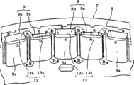
Below, referring to figs. 1 through Fig. 7 the 1st execution mode of the present invention is described.Fig. 1 is an integrally-built stereogram of roughly representing permanent magnet motor 1 (outer-rotor brushless motor).Permanent magnet motor 1 is made up of stator 2 and the rotor 3 that is located on the periphery of this stator 2.
Also as shown in Figure 2, stator 2 comprises stator core 4 and stator coil 5.Stator core 4 is to constitute through range upon range of multi-disc of the silicon steel plate as soft-magnetic body that stamping-out is formed and riveted joint (ca(u)lk).Stator core 4 have the 4a of yoke portion of ring-type and from the peripheral part of the 4a of this yoke portion with radial outstanding a plurality of tooth 4b of portion.The surface of stator core 4 except and the inner peripheral surface of rotor 3 between the interstitial outer peripheral face 4c (front end face of each 4b of tooth portion), covered by PET resin (moulded resin).In addition, a plurality of installation portions 6 that are made up of this PET resin are formed in the interior perimembranous of stator 2 integratedly.On these installation portions 6, be provided with a plurality of screwed hole 6a.Through with these installation portion 6 screw, stator 2 is fixed in the case on the back side of tank 25 (with reference to Fig. 6) of drum-type washing drying machine 21.Stator coil 5 is made up of three-phase, is wrapped on each 4b of tooth portion.
Also as shown in Figure 3, rotor 3 is with framework 7, rotor core 8 and a plurality of permanent magnet 9 incorporate structures through not shown moulded resin.Framework 7 is through forming the flat structure that the round-ended cylinder shape is arranged as the for example iron plate punch process of magnetic.Framework 7 has circular main board portion 7a and all sidewall 7c of the ring-type erect via the 7b of rank portion from the peripheral part of this main board portion 7a.At the central part of main board portion 7a, be provided with the axle installation portion 10 that is used for installing rotating shaft 26 (with reference to Fig. 6).Between this installation portion 10 and the 7b of rank portion, be radial a plurality of ventilation holes 11 and the floor 12 of being formed with in center with axle installation portion 10.
Rotor core 8 is that the range upon range of multi-disc of the silicon steel plate as soft-magnetic body and the riveted joint of ring-type constitute through stamping-out being formed roughly.Rotor core 8 is configured in the interior perimembranous of all sidewall 7c of framework 7.The inner peripheral surface of this rotor core 8 (and the outer peripheral face of stator 2 (the outer peripheral face 4c of stator core 4) opposed and and this stator 2 between interstitial face) form and have towards the inboard concavo-convex with circular-arc outstanding a plurality of protuberance 8a.
Also as shown in Figure 4,, be formed with vertically the rectangular-shaped patchhole 13 that (stacked direction of silicon steel plate) connects rotor core 8 in the inside of these a plurality of protuberance 8a.These a plurality of patchholes 13 are for to be configured in the structure on the rotor core 8 with ring-type.In addition, these a plurality of patchholes 13 are made up of the length of minor face different two kind patchhole 13a, 13b.In the case, the length of the minor face of patchhole 13a is 2.1mm, and the length of the minor face of patchhole 13b is 4.1mm.These patchholes 13a, 13b circumferentially alternately dispose along rotor core 8 one by one.
Permanent magnet 9 is made up of the rectangular-shaped SmCo magnet 9b (samarium-cobalt magnet=samarium-cobalt magnet) that is inserted in the rectangular-shaped neodium magnet 9a (Neodymiummagnet) among the patchhole 13a and be inserted among the patchhole 13b.That is, permanent magnet 9a is made up of the neodium magnet as rare earth element magnet, and permanent magnet 9b is made up of the SmCo magnet as rare earth element magnet.In the case, the coercive force of neodium magnet 9a is 900kA/m, and the coercive force of SmCo magnet 9b is about 200~500kA/m, and coercive force differs about 1.8~4.5 times.That is, permanent magnet 9 is made up of coercive force different two kind permanent magnet 9a, 9b.These permanent magnets 9a, 9b in rotor core 8 inside with ring-type roughly and alternately disposing one by one.
In addition, the permanent magnet 9a of these two kinds, 9b form 1 magnetic pole by a kind respectively, set into, make radially (from the direction in peripheral part the space towards stator 2 and rotor 3 between of permanent magnet motor 1) of its direction of magnetization along permanent magnet motor 1.Through like this with the permanent magnet 9a of two kinds, 9b alternately and make its direction of magnetization along radially disposing, permanent magnet 9a, the 9b of configuration adjacent one another are become the state that has magnetic pole each other in the opposite direction (one N is very inboard, another N very the state in the outside) thus.The direction of between these neodium magnets 9a and SmCo magnet 9b, following the usual practice shown in arrow B (with reference to Fig. 4) thus, produces magnetic-path (magnetic flux).In addition, in Fig. 4, the arrow of being represented by the dotted line of top is the magnetic flux via rotor core 8.Through such structure, form magnetic-path through the less SmCo magnet 9b of the bigger neodium magnet 9a of coercive force and coercive force.
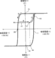
The magnetic characteristic of SmCo magnet 9b then, is described with reference to Fig. 5.Fig. 5 is the figure of relation of magnetic flux density and the magnetic field intensity of expression permanent magnet, magnetic flux density>0, magnetic field intensity 0 zone is the 2nd quadrant, magnetic flux density 0, < 0 zone is the 3rd quadrant to magnetic field intensity.In addition, in Fig. 5, dotted line P representes the magnetic characteristic of neodium magnet 9a, and solid line Q representes the magnetic characteristic of SmCo magnet 9b.
The magnetic characteristic of SmCo magnet 9b (relation of magnetic flux density and magnetic field intensity) is set to: its breakover point q in the temperature range of using (being the temperature range corresponding to the motor that uses, for example is 0 ℃~40 ℃ in the case) is present in the 2nd quadrant.In addition, the absolute value of the magnetic field intensity Hb of this breakover point q is below the 500kA/m (representing with label H among Fig. 5).
If breakover point is in the 2nd quadrant, then the coercive force Hcb of the magnetic field intensity Hb of this breakover point and permanent magnet is roughly the same.The magnetic field intensity of the permanent magnet of coercive force Hcb and generation is proportional.Therefore, the absolute value of coercive force Hcb (| Hcb|) be preferably bigger.In addition, the magnetic field intensity Hb of breakover point is proportional with the intensity of the external magnetic field that needs for intensity (magnetic flux) change (increasing magnetic or demagnetize) that makes permanent magnet.Coil current (flowing through the electric current of stator coil 5) when the intensity of the external magnetic field that in the change of magnetic flux, needs here, and magnetic flux change is proportional.Therefore, for the intensity of the needed external magnetic field of change that makes magnetic flux diminishes as far as possible, the absolute value of the magnetic field intensity Hb of breakover point (| Hb|) be preferably less.
Make coercive force Hcb absolute value (| Hcb|) become big characteristic and the absolute value that makes the magnetic field intensity Hb of breakover point (| the characteristic that Hb|) diminishes is in inverse relationship.If such two characteristics that are in inverse relationship are comprehensive, then the absolute value of coercive force Hcb and the ratio of the magnetic field intensity Hb of breakover point (| Hcb/Hb|) be preferably bigger.In addition, in the case, the magnetic field intensity Hb of coercive force Hcb and breakover point is a negative value.
Being under the situation of the 3rd quadrant (among Fig. 5 with reference to dotted line P) at breakover point p as neodium magnet 9a does | Hcb| | Hb|, so the absolute value of above-mentioned ratio | Hcb/Hb| is less than 1.On the other hand, be under the situation of the 2nd quadrant (among Fig. 5 with reference to solid line Q) at breakover point p as SmCo magnet 9b and do | Hcb| >=| Hb|, so the absolute value of above-mentioned ratio | Hcb/Hb| is more than 1.Thereby, compare with the situation that breakover point is in the 3rd quadrant, breakover point be in the 2nd quadrant situation more preferably.In the curve of expression magnetic characteristic, approach vertically than the keep left inclination of side of breakover point.Therefore, in the 2nd quadrant, having among the SmCo magnet 9b of breakover point q the absolute value of above-mentioned ratio | Hcb/Hb| changes not significantly.
In addition, in the household appliances as drum-type washing drying machine 21, the electric current that can in home-use power-supply system, use generally is about per 1 15A of system.Therefore, if consider such power supply situation, then the rated value of motor driven class component and control type circuit element is that the upper limit is preferred economically with 15A.The short-time rating value of these elements is roughly at double 30A of above-mentioned 15A.Motor being applied under the situation of this electric current, roughly is 500kA/m according to the magnetic field intensity of the breakover point of the needed electric current inverse of change of the magnetic flux of permanent magnet.Therefore, the magnetic field intensity of breakover point preferably is below this value (500kA/m) as SmCo magnet 9b.
In addition, if breakover point q is in the 2nd quadrant as SmCo magnet 9b, then the change amplitude of magnetic flux is bigger, and the ratio of the change amplitude that can make magnetic flux and the needed coil current of change of magnetic flux minimizes.
Then, the structure to the drum-type washing drying machine 21 that possesses above-mentioned such permanent magnet motor 1 that constitutes describes.Fig. 6 is a vertical profile end view of roughly representing the internal structure of drum-type washing drying machine 21.
The outer container 22 that forms the shell of drum-type washing drying machine 21 has the washings gateway 23 with the toroidal opening in front.This washings gateway 23 is opened and closed through door 24.In the inside of outer container 22, dispose the tank that the round-ended cylinder shape is arranged 25 that the back side is closed.Above-mentioned permanent magnet motor 1 (stator 2) is fixed on the back side central portion of this tank 25 through screw.The rearward end of the rotating shaft 26 of this permanent magnet motor 1 (being the end on right side in Fig. 6) is fixed on the axle installation portion 10 of permanent magnet motor 1 (rotor 3), and leading section (being the end in left side in Fig. 6) is projected in the tank 25.On the leading section of rotating shaft 26, fixing the cylinder that the round-ended cylinder shape is arranged 27 that the back side is closed, so that it is coaxial shape with respect to tank 25.This cylinder 27 rotates with rotor 3 and rotating shaft 26 through the driving of permanent magnet motor 1 integratedly.In addition, on cylinder 27, be provided with a plurality of baffle plates 29 that pick up and rub that can make the logical a plurality of openings 28 of air and current and be used for carrying out the washings in the cylinder 27.
On tank 25, connecting feed water valve 30, if this feed water valve 30 is open, then to would supplying water in the tank 25.In addition, on tank 25, connecting the scupper hose 32 with draining valve 31, if this draining valve 31 is open, then the water in the tank 25 is discharged from.
Below tank 25, be provided with the air pipe 33 of direction extension forwards, backwards.The leading section of this air pipe 33 is connected in the tank 25 via anterior pipeline 34.The rearward end of air pipe 33 is connected in the tank 25 via rear portion pipeline 35.On the rearward end of air pipe 33, be provided with Air Blast fan 36.Through the air-supply effect of this Air Blast fan 36, the air in the tank 25 is delivered in the air pipe 33, is got back in the tank 25 through rear portion pipeline 35 shown in arrow from anterior pipeline 34.
Dispose evaporator 37 in air pipe 33 inner front, dispose condenser 38 in air pipe 33 inner rear end side.These evaporators 37 and condenser 38 constitute heat pump 40 with compressor 39 and choke valve (not shown).Heat pump 40 will flow air circulate it through evaporator 37 dehumidifying, through condenser 38 heating in air pipe 33 in tank 25.
In the front of outer container 22, be positioned at door 24 top and be provided with guidance panel 41.On this guidance panel 41, be provided with a plurality of console switchs (not shown) that are used for setting running flow process etc.Guidance panel 41 is connected in the control circuit portion 42 (corresponding to control part).Control circuit portion 42 is that main body constitutes the whole running of index drum formula scrubbing-and-drying unit 21 with the microcomputer.This control circuit portion 42 carries out various running flow processs according to the content of setting via guidance panel 41 while control the driving of permanent magnet motor 1, feed water valve 30, draining valve 31, compressor 39, choke valve etc.
In addition, in permanent magnet motor 1, on the part that is opposite to permanent magnet 9, dispose the Magnetic Sensor 43 (with reference to Fig. 7) of the magnetic that detects this permanent magnet 9.This Magnetic Sensor 43 is assembled on the circuit substrate (not shown) that is installed on stator 2 sides.As shown in Figure 7, control circuit portion 42 is based on the position of rotation from the detection signal computing rotor 3 of this Magnetic Sensor 43.And,, drive the phase inverter 44 that 6 IGBT44a (in Fig. 7, only illustrating two) three phase bridge is formed through gate electrode drive signals G corresponding to this operation result.Thus, while controlling the energising of stator coil 5, control circuit portion 42 makes rotor 3 rotations.
Then, the effect that above-mentioned that kind is possessed the drum-type washing drying machine 21 of permanent magnet motor 1 describes.
If control circuit portion 42 is via 44 pairs of stator coils of phase inverter 5 energising, it is last that then the armature reaction external magnetic field of bringing (magnetic field that produces through the electric current that flows through stator coil 5) acts on permanent magnet 9a, the 9b of rotor 3.And, the magnetized state of the SmCo magnet 9b that the coercive force among these permanent magnets 9a, the 9b is less under the effect of the external magnetic field that this armature reaction brings by demagnetize or increase magnetic.Thus, can increase and decrease magnetic flux (flux of interlinkage) with stator coil 5 interlinkages.So in this execution mode, control circuit portion 42 is through the energising of control stator coil 5, the magnetized state of SmCo magnet 9b is switched according to running stroke (washing stroke, dehydration stroke, dry trip) and carries out.Here, the movement content in each running stroke is explained successively.
At first, in washing course, control circuit portion 42 is open and to supplying water in the tank 25 with feed water valve 30, then makes cylinder 27 rotations and washs.In this washing stroke, need make cylinder 27 with the high torque (HT) rotation for the washings that will contain water picks up, but rotary speed can be a low speed.So the energising of 44 pairs of stator coils 5 of control circuit portion 42 control phase inverters is so that the magnetized state of SmCo magnet 9b is increased magnetic.Thus, act on the magnetic flux quantitative change many (magnetic force grows) on the stator coil 5, so cylinder 27 is rotated with the high torque (HT) low velocity.
Then, in the dehydration process, control circuit portion 42 opens draining valve 31 and the water in the tank 25 is discharged the moisture dehydration that then will in washings, contain through making cylinder 27 high speed rotating.In this dehydration stroke, need make cylinder 27 with high speed rotating in order to improve dewatering efficiency, but torque also can be less.So the energising of 44 pairs of stator coils 5 of control circuit portion 42 control phase inverters is so that the magnetized state of SmCo magnet 9b is by demagnetize.Thus, the magnetic flux that acts on the stator coil 5 tails off (magnetic force dies down), so cylinder 27 is rotated with low torque at a high speed.
At last, in dry process, control circuit portion 42 carries out the drying of washings through driving Air Blast fan 36 and heat pump 40 and making cylinder 27 rotations.In this dry trip, control circuit portion 42 is that the washing stroke of next time is prepared, and the energising of 44 pairs of stator coils 5 of control phase inverter is so that the magnetized state of SmCo magnet 9b is increased magnetic.Thus, can become the many states of magnetic flux quantitative change that act on the stator coil 5.Thereby, in the washing stroke of next time, cylinder 27 is rotated with the high torque (HT) low velocity.
As described above, according to the permanent magnet motor 1 of this execution mode, the external magnetic field demagnetize that the magnetized state of the SmCo magnet 9b that two kind permanent magnet 9a that can coercive force is different, the coercive force among the 9b are less brings through armature reaction or increase magnetic.Thus, can carry out adjusting in this execution mode corresponding to the magnetic flux of the permanent magnet 9 of the load (being the cylinder 27 of drum-type washing drying machine 21) that drives.Thus, the magnetic flux of permanent magnet 9 always is not certain, degradation under the output when insulation breakdown in the time of can preventing high speed rotating and low speed rotation.
And two kind permanent magnet 9a, the 9b that coercive force is different are configured to be kind of per 1 magnetic pole and become roughly that the structure of ring-type is simple.Through so simple structure, can realize adjusting corresponding to the magnetic flux of the permanent magnet 9 of the load (cylinder 27) that drives.
In addition, the magnetic-path that forms through two kind permanent magnet 9a, 9b is all passed through both of the less SmCo magnet 9b of the bigger neodium magnet 9a of coercive force and coercive force.Thus, can make the magnetic flux of all magnetic-path roughly the same, can pass through stable magnetic flux head roll 27.
In addition, according to the drum-type washing drying machine 21 of this execution mode, can regulate the magnetic flux of permanent magnet 9 expeditiously corresponding to the running stroke.
(the 2nd execution mode)
Then, with reference to Fig. 8 and Fig. 9 the 2nd execution mode of the present invention is described.In addition, for omitting explanation, only different portions is described with above-mentioned the 1st execution mode same section.This execution mode replaces the SmCo magnet 9b that in the 1st execution mode, representes and uses neodium magnet 9c this point different.That is, permanent magnet 9a, 9c are made up of the neodium magnet as rare earth element magnet respectively.
As shown in Figure 8, permanent magnet 9 is made up of the rectangular-shaped neodium magnet 9c that is inserted in the rectangular-shaped neodium magnet 9a among the patchhole 13a and be inserted among the patchhole 13b.In the case, the coercive force of neodium magnet 9a is about 900kA/m, and the coercive force of neodium magnet 9c is about 200kA/m, and coercive force differs about 4.5 times.That is, permanent magnet 9 is made up of coercive force different two kind permanent magnet 9a, 9c.These permanent magnets 9a, 9c in rotor core 8 inside with ring-type roughly and alternately configuration one by one.
In addition, these two kind permanent magnet 9a, 9c form 1 magnetic pole by a kind respectively, set into, make radially (from the direction in peripheral part the space towards stator 2 and rotor 3 between of permanent magnet motor 1) of its direction of magnetization along permanent magnet motor 1.Through like this with two kind permanent magnet 9a, 9c alternately and make its direction of magnetization along radially disposing, the permanent magnet 9a of configuration adjacent one another are, 9c become the state that has magnetic pole each other in the opposite direction (one N is very inboard, another N very the state in the outside).The direction of between these neodium magnets 9a and neodium magnet 9c, following the usual practice shown in arrow B (with reference to Fig. 8) thus, produces magnetic-path (magnetic flux).In addition, in Fig. 8, the arrow of being represented by the dotted line of top is the magnetic flux via rotor core 8.Through such structure, form magnetic-path through the less neodium magnet 9c of the bigger neodium magnet 9a of coercive force and coercive force.
The magnetic characteristic of neodium magnet 9c then, is described with reference to Fig. 9.In Fig. 9, dotted line P representes the magnetic characteristic of neodium magnet 9a, and solid line R representes the magnetic characteristic of neodium magnet 9c.
The magnetic characteristic of neodium magnet 9c (relation of magnetic flux density and magnetic field intensity) is set to; Make its breakover point q in temperature range of using (being the temperature range corresponding to the motor that uses, for example is 0 ℃~40 ℃ in the case) be present in the 2nd quadrant (magnetic flux density>0, magnetic field intensity 0 zone) in.In addition, the absolute value of the magnetic field intensity Hb of this breakover point q is below the 500kA/m (representing with label H among Fig. 9).
If breakover point is in the 2nd quadrant, then the coercive force Hcb of the magnetic field intensity Hb of this breakover point and permanent magnet is roughly the same.The magnetic field intensity of the permanent magnet of coercive force Hcb and generation is proportional.Therefore, the absolute value of coercive force Hcb (| Hcb|) be preferably bigger.In addition, the magnetic field intensity Hb of breakover point is proportional with the intensity of the external magnetic field that needs for intensity (magnetic flux) change (increasing magnetic or demagnetize) that makes permanent magnet.Coil current (flowing through the electric current of stator coil 5) when the intensity of the external magnetic field that in the change of magnetic flux, needs here, and magnetic flux change is proportional.Therefore, for the intensity of the needed external magnetic field of change that makes magnetic flux diminishes as far as possible, the absolute value of the magnetic field intensity Hb of breakover point (| Hb|) be preferably less.
Make coercive force Hcb absolute value (| Hcb|) become big characteristic and the absolute value that makes the magnetic field intensity Hb of breakover point (| the characteristic that Hb|) diminishes is in inverse relationship.If such two characteristics that are in inverse relationship are comprehensive, then the absolute value of coercive force Hcb and the ratio of the magnetic field intensity Hb of breakover point (| Hcb/Hb|) be preferably bigger.In addition, in the case, the magnetic field intensity Hb of coercive force Hcb and breakover point is a negative value.
Breakover point p as neodium magnet 9a be in the 3rd quadrant (magnetic flux density 0, magnetic field intensity 0 zone) situation under (among Fig. 9 with reference to dotted line P) do | Hcb| | Hb|, so the absolute value of above-mentioned ratio | Hcb/Hb| is less than 1.On the other hand, be under the situation of the 2nd quadrant (among Fig. 9 with reference to solid line R) at breakover point q as neodium magnet 9c and do | Hcb| >=| Hb|, so the absolute value of above-mentioned ratio | Hcb/Hb| is more than 1.Thereby, compare with the situation that breakover point is in the 3rd quadrant, breakover point be in the 2nd quadrant situation more preferably.In the curve of expression magnetic characteristic, approach vertically than the keep left inclination of side of breakover point.Therefore, in the 2nd quadrant, having among the neodium magnet 9c of breakover point q the absolute value of above-mentioned ratio | Hcb/Hb| changes not significantly.
In addition, in the household appliances as drum-type washing drying machine 21, the electric current that can in home-use power-supply system, use generally is about per 1 15A of system.Therefore, if consider such power supply situation, then the rated value of motor driven class component and control type circuit element is that the upper limit is preferred economically with 15A.The short-time rating value of these elements is roughly at double 30A of above-mentioned 15A.Motor being applied under the situation of this electric current, roughly is 500kA/m according to the magnetic field intensity of the breakover point of the needed electric current inverse of change of the magnetic flux of permanent magnet.Therefore, the magnetic field intensity of breakover point preferably is below this value (500kA/m) as neodium magnet 9c.
In addition, if breakover point q is in the 2nd quadrant as neodium magnet 9c, then the change amplitude of magnetic flux is bigger, and the ratio of the change amplitude that can make magnetic flux and the needed coil current of change of magnetic flux minimizes.
(the 3rd execution mode)
Then, with reference to Figure 10 the 3rd execution mode of the present invention is described.In addition, for omitting explanation, only different portions is described with above-mentioned the 1st execution mode same section.This execution mode replaces the SmCo magnet 9b that in the 1st execution mode, representes and uses alnico magnet 9d (aluminium-nickel-cobalt magnet=aluminium, nickel and cobalt) this point different.
Shown in figure 10, permanent magnet 9 is made up of the rectangular-shaped alnico magnet 9d that is inserted in the rectangular-shaped neodium magnet 9a among the patchhole 13a and be inserted among the patchhole 13b.In the case, the coercive force of neodium magnet 9a is about 900kA/m, and the coercive force of alnico magnet 9d is about 100kA/m, and coercive force differs about 9 times.That is, permanent magnet 9 is made up of coercive force different two kind permanent magnet 9a, 9d.These permanent magnets 9a, 9d in rotor core 8 inside with ring-type roughly and alternately configuration one by one.
In addition, these two kind permanent magnet 9a, 9d form 1 magnetic pole by a kind respectively, set into, make radially (from the direction in peripheral part the space towards stator 2 and rotor 3 between of permanent magnet motor 1) of its direction of magnetization along permanent magnet motor 1.Through like this with two kind permanent magnet 9a, 9d alternately and make its direction of magnetization along radially disposing, permanent magnet 9a, the 9d of configuration adjacent one another are become the state that has magnetic pole each other in the opposite direction (one N is very inboard, another N very the state in the outside) thus.The direction of between these neodium magnets 9a and alnico magnet 9d, following the usual practice shown in arrow B (with reference to Figure 10) thus, produces magnetic-path (magnetic flux).In addition, in Figure 10, the arrow of being represented by the dotted line of top is the magnetic flux via rotor core 8.Through such structure, form magnetic-path through the less alnico magnet 9d of the bigger neodium magnet 9a of coercive force and coercive force.
Alnico magnet 9d has and above-mentioned SmCo magnet 9b, the approximate magnetic characteristic (with reference to the solid line Q of Fig. 5, the solid line R of Fig. 9) of neodium magnet 9c.Thereby; Same with the situation of using these SmCo magnet 9b, neodium magnet 9c; Through the structure of this execution mode, also can make the change amplitude of magnetic flux become big, and the ratio of the change amplitude that can make magnetic flux and the needed coil current of change of magnetic flux minimize.
(the 4th execution mode)
Then, with reference to Figure 11 and Figure 12 the 4th execution mode of the present invention is described.In addition; In this execution mode; For the structure same (replace SmCo magnet 9b and use the structure of neodium magnet 9c), not with reference to the magnetic flux density of neodium magnet 9c and the relation of magnetic field intensity (with reference to Fig. 9) but describe with reference to the magnetic polarization of neodium magnet 9c and the relation of magnetic field intensity with above-mentioned the 2nd execution mode.
At first, with reference to Figure 11 the magnetic characteristic with the situation of neodium magnet 9c demagnetize is described.Figure 11 is the figure of relation of magnetic polarization and the magnetic field intensity of expression neodium magnet 9c.In Figure 11, solid line J is that saturated poleization (Js) from neodium magnet 9c is to saturated poleization (B-H loop Js) (datum curve) of antipole.In Figure 11, solid line j1 is via the B-H loop (back-up curve) of the some T1 that increases magnetic side (being the right side) in Figure 11 to the some S1 that in datum curve J, is present in the 1st quadrant from the some R1 that among datum curve J, is present in the 2nd quadrant.In this execution mode, under the situation with neodium magnet 9c demagnetize, the operating point of this neodium magnet 9c is along back-up curve j1 displacement in the zone of the 1st quadrant and the 2nd quadrant.
Here, some R1 the some Js from principal curve J (magnetic field intensity=0, magnetic polarization=Js) to a some H1 (magnetic field intensity=-Hcj (confining force of neodium magnet 9c), magnetic polarization=0) the zone, promptly can set point arbitrarily on the principal curve J in the 2nd quadrant.Point T1 is set at, and makes its magnetic field intensity become the roughly the same size of magnetic field intensity of the flex point A1 of the magnetic susceptibility in the 4th quadrant with principal curve J.Point S1 is the point that back-up curve j1 is gradually to principal curve J in the 1st quadrant.
And, the zone from a R1 to a T1 in back-up curve j1, increase characteristic that magnetic magnetic field, magnetic polarization also do not increase, be that magnetic susceptibility is roughly 0 magnetic characteristic even neodium magnet 9c has effect.In addition, if neodium magnet 9c has the magnetic characteristic that surpasses the increasing that magnetic the action of a magnetic field, magnetic susceptibility increase significantly of some T1 and be gradually to principal curve J at a S1 place.
For the neodium magnet 9c with such magnetic characteristic, 5 energisings of 42 pairs of stator coils of control circuit portion are so that the reciprocal external magnetic field of the direction of magnetization (demagnetize magnetic field) of its generation and this neodium magnet 9c.So, through the effect in this demagnetize magnetic field, the operating point of neodium magnet 9c on principal curve J to demagnetize side (reference arrow A in Figure 11) displacement.
Then, when the operating point point of arrival R1 of neodium magnet 9c, stop the energising of control circuit portion 42, stop the generation (external magnetic field is removed) of external magnetic field to stator coil 5.So, the operating point of neodium magnet 9c under the effect in the magnetic field of the neodium magnet 9a bigger than neodium magnet 9c coercive force, on back-up curve j1 to increase magnetic side (being the right side) displacement (reference arrow B in Figure 11) in Figure 11.
At this moment, if the magnetic field intensity that increases magnetic magnetic field absolute value ratio point T1 of neodium magnet 9a is little, then the some R1 of the operating point of neodium magnet 9c on back-up curve j1 stops in the zone of a T1.In the case, the point that the operating point of neodium magnet 9c stops is the demagnetize magnetic field (magnetic field that on the direction opposite with the direction of magnetization of neodium magnet 9c, produces) that in this neodium magnet 9c self, produces with neodium magnet 9a increase the balanced point in magnetic magnetic field.Thus, can keep the big or small roughly the same state (neodium magnet 9c is by the state of demagnetize) of magnetic polarization with the magnetic polarization of putting R1 of neodium magnet 9c.Thereby, can stably obtain the permanent magnet 9c that magnetic flux tails off through demagnetize.
But if the magnetic field intensity absolute value that increases magnetic magnetic field ratio point T1 of neodium magnet 9a is big, then the operating point of neodium magnet 9c reaches via a S1 (reference arrow C in Figure 11) on the principal curve J increasing magnetic side disengaging back-up curve j1.In the case, the magnetic polarization of neodium magnet 9c becomes bigger than the magnetic polarization (magnetic polarization behind the demagnetize) of a R1.That is, the magnetic flux of the neodium magnet 9c behind the demagnetize is got back to the preceding magnetic flux of demagnetize (making demagnetize the action of a magnetic field magnetic flux before).Thereby, no longer can stably obtain the neodium magnet 9c that tails off because of demagnetize magnetic flux.
Therefore, the zone from a R1 to a T1 (magnetic susceptibility is roughly 0 zone) is preferred more greatly more in back-up curve j1.Thereby the magnetic field intensity of some T1 can be set at the roughly the same size of the magnetic field intensity of flex point A1 of the magnetic susceptibility that in principal curve J, is present in the 4th quadrant as stated, or bigger than the magnetic field intensity of flex point A1.
Then, with reference to Figure 12 explanation neodium magnet 9c is increased the magnetic characteristic of the situation of magnetic.Figure 12 is the figure of relation of magnetic polarization and the magnetic field intensity of expression neodium magnet 9c.In Figure 12, solid line J is identical with the B-H loop J shown in Figure 11.In Figure 12, solid line j2 is the B-H loop (back-up curve) that reaches the some S2 that in principal curve J, is present in the 2nd quadrant from the some R2 that among principal curve J, is present in the 1st quadrant in Figure 12 via the some T2 of demagnetize side (being the left side).In this execution mode, neodium magnet 9c is being increased under the situation of magnetic, the operating point of this neodium magnet 9c is along back-up curve j2 displacement in the zone of the 1st quadrant and the 2nd quadrant.
Here, (point arbitrarily, promptly can be set on the principal curve J in the 1st quadrant at the zone of magnetic polarization=Js) in magnetic field intensity=0 to the some point H2 (magnetic field intensity=Hcj (confining force of neodium magnet 9c), magnetic polarization=0) of R2 on principal curve J to a some Js.Point T2 is set at, make its magnetic field intensity for the 2nd quadrant of principal curve J in the roughly the same size of magnetic field intensity of flex point A2 of magnetic susceptibility.Point S2 is the point that back-up curve j2 is gradually to principal curve J in the 2nd quadrant.
And, the zone from a R2 to a T2 on back-up curve j2, even neodium magnet 9c has effect demagnetize magnetic field, the also nondecreasing characteristic of magnetic polarization, is that magnetic susceptibility is roughly 0 magnetic characteristic.In addition, if having that the demagnetize the action of a magnetic field, the magnetic susceptibility that surpass some T2 reduce significantly, neodium magnet 9c is gradually to the magnetic characteristic of principal curve J at a S2 place.
For the neodium magnet 9c with such magnetic characteristic, 5 energisings of 42 pairs of stator coils of control circuit portion are so that the external magnetic field (increasing magnetic magnetic field) of the direction of magnetization equidirectional of its generation and this neodium magnet 9c.So, increase the effect in magnetic magnetic field through this, the operating point of neodium magnet 9c on principal curve J to increasing magnetic side (reference arrow D in Figure 12) displacement.
Then; When the operating point point of arrival R2 of neodium magnet 9c; If stop the energising of control circuit portion 42 to stator coil 5; Stop the generation (external magnetic field is removed) of external magnetic field, then under the effect in the demagnetize magnetic field (in the magnetic field that the direction of magnetization rightabout with neodium magnet 9c produces) that in this neodium magnet 9c self, produces of the operating point of neodium magnet 9c, on back-up curve j2 to demagnetize side (being the left side in Figure 12) displacement (reference arrow E in Figure 12).
At this moment, if the demagnetize magnetic field absolute value that in neodium magnet 9c self, produces is littler than the magnetic field intensity of some T2, then the some R2 of the operating point of neodium magnet 9c on back-up curve j2 stops in the zone of a T2.In the case, the point that the operating point of neodium magnet 9c stops, be the demagnetize magnetic field that in this neodium magnet 9c self, produces and neodium magnet 9a increase the balanced point in magnetic magnetic field.Thus, can keep the big or small roughly the same state (neodium magnet 9c is increased the state of magnetic) of magnetic polarization with the magnetic polarization of putting R2 of neodium magnet 9c.Thereby, can stably obtain the many permanent magnet 9c of magnetic flux quantitative change through increasing magnetic.
But if the demagnetize magnetic field that in neodium magnet 9c self, produces is bigger than the magnetic field intensity absolute value of some T2, then the operating point of neodium magnet 9c breaks away from back-up curve j2 to the demagnetize side, reaches via a S2 (reference arrow F in Figure 12) on the principal curve J.In the case, the magnetic polarization of neodium magnet 9c becomes littler than the magnetic polarization of a R2 (increase magnetic after magnetic polarization).That is the magnetic flux that, increases the neodium magnet 9c behind the magnetic is got back to the magnetic flux that increases before the magnetic (making the magnetic flux that increases before the magnetic the action of a magnetic field).Thereby, no longer can stably obtain because of increasing the many permanent magnet 9c of magnetic magnetic flux quantitative change.
Therefore, the zone from a R2 to a T2 (magnetic susceptibility is roughly 0 zone) is preferred more greatly more in back-up curve j2.Thereby the magnetic field intensity of some T2 can be set at the roughly the same size of the magnetic field intensity of flex point A2 of the magnetic susceptibility that in principal curve J, is present in the 2nd quadrant as stated, or than the magnetic field intensity little (absolute value is big) of flex point A2.
As described above, according to this execution mode, can be with demagnetize or the magnetized state of the neodium magnet 9c after increasing magnetic under this state, keep.Thus, can stably regulate the magnetized state of permanent magnet 9, can make the adjustable range of the magnetic flux of this permanent magnet 9 become big.
In addition,, the magnetic flux of permanent magnet 9 can be regulated expeditiously, the electric power that consumes in order to drive permanent magnet motor 1 can be suppressed according to the permanent magnet motor 1 that uses such permanent magnet 9.
(other execution modes)
The present invention is not limited to above-mentioned each execution mode, can distortion or expansion as following.
As two different kind permanent magnets 9 of coercive force, be not limited to combination and the combination of neodium magnet 9a and alnico magnet 9d of combination, neodium magnet 9a and the neodium magnet 9c of neodium magnet 9a and SmCo magnet 9b, also can use the permanent magnet of other kinds.In addition, the coercive force of these two kind permanent magnets 9 is preferably and differs roughly more than 2 times.
In addition, permanent magnet 9 is not limited to two kinds, can be that 3 kinds of large, medium and small permanent magnets constitute by coercive force also, also can be made up of a plurality of kind permanent magnets of 4 kinds or 5 kinds etc.In the case, control circuit portion 42 can be according to the magnetized state of the less relatively permanent magnet of the coercive force in these permanent magnets of running stroke switching.
As the means of the magnetic flux of regulating permanent magnet 9, be not limited to structure through phase inverter 44 control stator coils 5, for example also can make the coil that is provided with in addition with stator coil 5, the structure of controlling the energising of this coil are set.
Permanent magnet motor 1 of the present invention axially is also can use in the rinsing maching of longitudinal axis type longitudinally in above-mentioned drum washing drier 21, at the rinsing maching that does not have functions/drying, swivelling chute not only.In addition, the present invention not only also can use in the inner-rotor type motor in the outer-rotor type permanent magnet motor 1 of above-mentioned that kind, on the interior week that rotor is located at stator.And then, can use in the various motors such as motor that the driven compressor of permanent magnet motor 1 of the present invention in being equipped on air-conditioning etc. used.