CN101417759B - Sheet processing apparatus and image forming apparatus - Google Patents
Sheet processing apparatus and image forming apparatus Download PDFInfo
- Publication number
- CN101417759B CN101417759B CN2008101673499A CN200810167349A CN101417759B CN 101417759 B CN101417759 B CN 101417759B CN 2008101673499 A CN2008101673499 A CN 2008101673499A CN 200810167349 A CN200810167349 A CN 200810167349A CN 101417759 B CN101417759 B CN 101417759B
- Authority
- CN
- China
- Prior art keywords
- thin slice
- folding
- planarization
- bundle
- roller
- Prior art date
- Legal status (The legal status is an assumption and is not a legal conclusion. Google has not performed a legal analysis and makes no representation as to the accuracy of the status listed.)
- Expired - Fee Related
Links
Images


Classifications
-
- B—PERFORMING OPERATIONS; TRANSPORTING
- B65—CONVEYING; PACKING; STORING; HANDLING THIN OR FILAMENTARY MATERIAL
- B65H—HANDLING THIN OR FILAMENTARY MATERIAL, e.g. SHEETS, WEBS, CABLES
- B65H2701/00—Handled material; Storage means
- B65H2701/10—Handled articles or webs
- B65H2701/13—Parts concerned of the handled material
- B65H2701/132—Side portions
- B65H2701/1321—Side portions of folded article or web
- B65H2701/13212—Fold, spine portion of folded article
Abstract
A sheet processing apparatus includes a folding apparatus 556 which folds a sheet bundle, a switching portion which switches a nipping pressure by the folding apparatus 556 against the sheet bundle, and a flattening apparatus 700 which presses and flattens a folded-back portion of the folded sheet bundle, and the switching portion operates such that the nipping pressure by the folding apparatus 556 against the sheet bundle when the flattening processing is executed becomes weaker than that of the folding apparatus 556 when the flattening processing is not executed.
Description
Technical field
The present invention relates to a kind of sheet processing apparatus of the folding spine portion planarization that can make centre-stitched thin slice bundle and image forming apparatus with this sheet processing apparatus.
Background technology
Proposed a kind ofly to pile up the sheet processing apparatus that thin slice carries out centre-stitched (saddle-stitch), wherein piled up at these and formed image on thin slice by image forming apparatus to a plurality of.Proposed a kind ofly can utilize roller to push the folding ridge surface (order and sew side) of centre-stitched thin slice bundle and can make the equipment (TOHKEMY 2004-345863) of this folding having an even surface of ridge as shown in figure 25.
In as image forming apparatus such as duplicator, proposed a kind of like this image formation system: this image formation system will be generated as saddle stitching binding material (TOHKEMY 2005-239414) from the thin slice of image forming apparatus output by having the sheet processing apparatus of saddle stitching binder mechanism and planarization mechanism.
In addition, in as image forming apparatus such as duplicator, a kind of like this sheet processing apparatus has been proposed: this sheet processing apparatus control planarization, make the overhang of folding spine portion of thin slice bundle change, thereby make the width of folding ridge be suitable for this thickness (TOHKEMY 2006-290588) according to the thickness of thin slice bundle.
In the folding stapling operation of centre-stitched or central authorities, if the booklet after as-is condition keeps finishing, then this booklet opens slightly, and its appearance degradation in some cases.For anti-problem here, conceived a kind of structure that is used for when central folding operation, strengthening folding pressure.
Yet, when the folding ridge surface of planarization central authorities folding bookbinding booklet when forming spine, if the folding pressure of central authorities is too strong, then as shown in figure 25, the folding folding line 980 of central authorities is retained on the spine, and the appearance degradation of the spine after finishing in some cases.Particularly when forming image on spine, image might break along this folding line, and the appearance degradation after finishing.
According to whether should carrying out planarization, central authorities are folding, and to handle needed technology different fully, but change about the selection that whether should the carry out planarization booklet type according to user's expectation.
Summary of the invention
Consider above point and finished the present invention, and the invention provides and a kind ofly can change the sheet processing apparatus and the image forming apparatus of the folding pressure of central authorities according to whether carrying out planarization.
A kind of sheet processing apparatus comprises: folding means is used for clamping and folded sheet bundle; Planarizing unit is used to push by described folding means the folding spine portion of the described thin slice bundle after folding, thereby makes described folding spine portion planarization; And switching part, be used to switch the clamp pressure of described folding means to described thin slice bundle, wherein, described switching part switches, and feasible described clamp pressure when being provided with planarization is less than the described clamp pressure when described planarization is not set.
Image forming apparatus of the present invention comprises: image forming part is used for forming image on thin slice; And sheet processing apparatus, the described sheet fold that is used for having formed image by described image forming part becomes two parts, and makes described thin slice planarization.
In the present invention, by according to whether changing clamp pressure, can eliminate the lip-deep situation that folding line is retained in spine effectively to thin slice Shu Jinhang planarization.Utilize this operation, can prevent that the image on the spine from breaking.
According to following (with reference to the accompanying drawings) explanation to exemplary embodiments, further feature of the present invention will be apparent.
Description of drawings
Fig. 1 illustrates integrally-built figure;
Fig. 2 is the integrally-built block diagram that the controller of the entire image forming device shown in the control chart 1 is shown;
Fig. 3 is the key drawing of operation display part;
Fig. 4 is the cross sectional drawing of automatic collating unit;
Fig. 5 is the block diagram of automatic collating unit;
Fig. 6 is the figure of the flow process of the paper in the automatic collating unit when being illustrated in stapling mode;
Fig. 7 is the figure of the flow process of the paper in the automatic collating unit when being illustrated in stapling mode;
Fig. 8 is the figure of the flow process of the paper in the automatic collating unit when being illustrated in stapling mode;
Fig. 9 is the figure of the flow process of the paper in the automatic collating unit when being illustrated in stapling mode;
Figure 10 is the figure of the flow process of the paper in the automatic collating unit when being illustrated in stapling mode;
Figure 11 A and 11B are the cross sectional drawing and the planar views of flattening device;
Figure 12 is the block diagram of flattening device;
Figure 13 A and 13B are the figure of flow process that the paper of flattening device is shown;
Figure 14 A and 14B are the figure of flow process that the paper of flattening device is shown;
Figure 15 A and 15B are the figure of flow process that the paper of flattening device is shown;
Figure 16 A and 16B are the figure of flow process that the paper of flattening device is shown;
Figure 17 is the key drawing that picture is set of stapling mode;
Figure 18 is the key drawing that picture is set of stapling mode;
Figure 19 is the key drawing that picture is set of stapling mode;
Figure 20 is the figure that illustrates according to the operation of the folding roller of stapling mode;
Figure 21 is the figure that illustrates according to the operation of the folding roller of stapling mode;
Figure 22 is the figure that illustrates according to the operation of the folding roller of stapling mode;
Figure 23 is the figure that illustrates according to the operation of the folding roller of stapling mode;
Figure 24 is the diagram of circuit of the separating treatment of folding roller; And
Figure 25 is the key drawing of conventional art.
The specific embodiment
With sheet processing apparatus and the image forming apparatus that describes in detail with reference to the accompanying drawings according to the embodiment of the invention.
First embodiment
Integral structure
Fig. 1 is the figure of whole keystone configuration that the embodiment of image forming apparatus of the present invention is shown.
As shown in FIG. 1, image forming apparatus comprises image forming apparatus main body 10 and sheet processing apparatus.Sheet processing apparatus comprises automatic collating unit 500 and flattening device 700.Image forming apparatus main body 10 comprises the cis 200 of the image that reads original copy and has the chopping machine 300 that forms the image forming part of image on thin slice.
Cis 200 disposes original copy supply arrangement 100.In original copy mode up original copy is placed in the original copy pallet 101.Original copy supply arrangement 100 is supplied with original copy left one by one from uppermost page or leaf, and original copy supply arrangement 100 reads the position via flowing from left to right by crooked route and carry original copy on plate glass 102, then original copy is discharged to the outside pallet 112 of discharging.When original copy reads the position by flowing from left to right, remain on the image that reads this original copy with the mobile scanner unit 104 that reads corresponding position, position.This read method is commonly referred to " original copy is browsed ".More specifically, when original copy reads the position by flowing, utilize the illumination of the lamp 103 of scanner unit 104 to penetrate original copy and read the surface, and will be directed to lens 108 from the reflected light of original copy by catadioptre 105,106 and 107.The light of scioptics 108 forms image on the shooting surface of imageing sensor 109.
, carry out original copy and read scanning so that these original copys read the position by flowing from left to right by carrying original copy by this way, make that the direction vertical with the throughput direction of original copy is main scanning direction, and throughput direction is a sub scanning direction.That is, when original copy reads the position by flowing, when main scanning direction reads original image line by line, carry this original copy along sub scanning direction at imageing sensor 109.Utilize this operation, read whole original image, and optically read image transitions is become view data and exports this view data by imageing sensor 109.From the described in the back picture signal control setup of view data of imageing sensor 109 outputs,, be input to the exposure-control device 110 of chopping machine 300 then as vision signal through predetermined process.
Can also original copy be transported on the plate glass 102 and with original copy by original copy supply arrangement 100 and stop at the pre-position, and allow scanner unit 104 scan manuscript from left to right in this state, thereby read this original copy.To be that so-called original copy is static read this read method.
When reading original copy under the situation of not using original copy supply arrangement 100, the user at first lifts original copy supply arrangement 100 and original copy is placed on the plate glass 102, and allows scanner unit 104 to scan this original copy from left to right, thereby reads original copy.That is, when under the situation of not using original copy supply arrangement 100, reading original copy, carry out that original copy is static to be read.
The exposure-control device 110 of chopping machine 300 comes modulated laser based on incoming video signal and exports this laser, and is scanned this laser and utilized this illumination to penetrate photosensitive drums 111 by polygonal mirror 110a.On photosensitive drums 111, form and the corresponding electrostatic latent image of laser that is scanned.As described in inciting somebody to action in the back, exposure-control device 110 output laser, the feasible correct image (non-mirror image) that forms when original copy is static to be read.
Make the electrostatic latent image on the photosensitive drums 111 be visualized as the developer image by the developer of supplying with from developing apparatus 113.With beginning irradiating laser synchronous timing place, by comprising foil roll 127 and 128, separate roller 129 and 130 and the delivery section of registration roller 126, from box 114 and 115, manually supply unit 125 or two-sided transport path 124 are carried thin slices.Between photosensitive drums 111 and transfer printing portion 116, carry this thin slice.To be formed on developer image on the photosensitive drums 111 to the thin slice of supplying with from transfer printing portion 116.
With transfer printing the thin slice of developer image be transported to photographic fixing portion 117.117 pairs of these thin slices of photographic fixing portion heat and pressurize, thus with the developer image fixing on this thin slice.To pass through the thin slice of photographic fixing portion 117 by switching member 121 and distributing roller 118 and discharge (to automatic collating unit 500) from chopping machine 300.Switching member 121 changes throughput direction.
When the image formation surface of thin slice towards below when discharging this thin slice under the state of (facing down), the thin slice that the blocked operation by switching member 121 will pass through photographic fixing portion 117 temporarily is directed in the reversing paths 122.After switching member 121 is passed through in the rear end of thin slice, this thin slice is gone back to, and discharge these thin slices from chopping machine 300 by distributing roller 118.This discharge type is called counter-rotating and discharges.When uppermost page or leaf forms image in turn, for example when form when using the image that original copy supply arrangement 100 reads, when forming from image that computing machine is exported, carry out this counter-rotating discharge.Thin slice after discharging is correct page or leaf order in proper order.
When sending hard thin slice such as OHP thin slices from manual supply unit 125 and when these thin slices form images, discharging these thin slices, make image formation surface (face up), and need not this thin slice is directed in the reversing paths 122 towards the top by distributing roller 118.
When the dual-side image that all forms image on two surfaces that are arranged in thin slice formed, the blocked operation by switching member 121 was directed to thin slice in the reversing paths 122 and this thin slice is transported to two-sided transport path 124.Control, make to be between photosensitive drums 111 and the transfer printing portion 116 to send the thin slice that is directed into two-sided transport path 124 once more in above-mentioned timing.
To send to automatic collating unit 500 from the thin slice that chopping machine 300 is discharged.Automatic collating unit 500 carries out sewing processing various processing such as (stitching processing) as ordering, and as flattening device 700 crimping of planarizing unit order sew or folding after central fold surface, thereby carry out planarization.
System chart
Then, the structure of the controller of control entire image forming device will be described with reference to figure 2.Fig. 2 is the integrally-built block diagram that the controller of the entire image forming device shown in the control chart 1 is shown.
As shown in FIG. 2, controller comprises cpu circuit portion 900.Cpu circuit portion 900 comprises CPU (not shown), ROM901 and RAM902.Be stored in each piece of the unified control of control program, original copy supply arrangement control setup 911, cis control setup 921, picture signal control setup 922, printer control device 931, operation display device control setup 941 and automatic collating unit control setup 951 among the ROM901.The interim retentive control data of RAM902, and be used as the work area of the computing that causes by control.
Original copy supply arrangement control setup 911 drives based on the instruction from cpu circuit portion 900 and control original copy supply arrangement 100.Cis control setup 921 drives and gated sweep device unit 104 and imageing sensor 109, and analog signal is transferred to picture signal control setup 922 from imageing sensor 109.
Picture signal control setup 922 will convert digital signal to and carry out various processing from the analog picture signal of imageing sensor 109, and this digital signal is converted to vision signal and this vision signal is outputed to printer control device 931.In addition, the data image signal of importing from computing machine 903 by exterior I/F904 is carried out various processing, this data image signal is converted to vision signal and this vision signal is outputed to printer control device 931.The processing operation of cpu circuit portion 900 control chart image signal control setups 922.Printer control device 931 drives exposure-control device 110 based on incoming video signal.
Operation display device control setup 941 is exchange message between operation display device 400 (referring to Fig. 1) and cpu circuit portion 900.Operation display device 400 comprises and is used to be provided with a plurality of keys of the various functions that form about image and is used to show that expression is provided with the display part of the information of state.To output to cpu circuit portion 900 with the corresponding key signals of the operation of each key, and on display part, show corresponding information based on signal from cpu circuit portion 900.
Flattening device 700 disposes planarization control setup 971.This planarization control setup 971 and automatic collating unit control setup 951 exchange messages and driving and control planarization.The back will illustrate this control.
Operation display device
Fig. 3 is the figure that is illustrated in the operation display device 400 in the image forming apparatus shown in Fig. 1.Be arranged in having on the operation display device 400: initiating key 402 is used to begin image and forms operation; Stop key 403 is used for ending image temporarily and forms operation; Numerical key 404 to 412 and 414 is used to be provided with numeral; ID key 413; Clearing key 415; And reset key 416, be used to be provided with various devices.Operation display device 400 is provided with the liquid crystal display part 420 with touch panel at an upper portion thereof, and can form soft key on its picture.
As the post-processing pattern, image forming apparatus has as nonpageable pattern, paging mode, orders various tupes such as dolly set formula (staple mode) (ordering the louver moudling formula) and stapling mode.By input operation this tupe is set from operation display device 400.When the post-processing pattern will be set, if select soft key " paging device " in initial picture as shown in Figure 3, then display menu was selected picture on liquid crystal display part 420, and used this menu to select picture to come the set handling pattern.
Automatic collating unit
Then, the structure of automatic collating unit 500 will be described with reference to figure 4.Fig. 4 is the cross sectional drawing of the automatic collating unit 500 shown in Fig. 1.
As shown in FIG. 4, according to automatic collating unit 500, be taken into the thin slice of discharging to 501, and will send to buffer roll 503 to 501 thin slices that are taken into by the inlet roller to 502 by conveying roller from image forming apparatus main body 10 by the inlet roller.At the inlet roller to 501 and the centre portion inlet porting sensor 570 of the transport path of conveying roller between to 502.
Can with by conveying roller to the sheet lamination of 502 predetermined quantities that send and be wound on the periphery of buffer roll 503.When buffer roll 503 rotation, by lower compression roller 504,505 and 506 with the periphery of winding of webs in buffer roll 503.Hand of rotation along buffer roll 503 is carried the thin slice of being reeled.
When the thin slice on will being wound on buffer roll 503 was directed to nonpageable path 509, switching member 507 work was with from buffer roll 503 peeling sheet, and this thin slice is directed to nonpageable path 509.By distributing roller 512 thin slices that will be directed to nonpageable path 509 are discharged on the sample tray 590.Centre portion in nonpageable path 509 is provided with discharge path sensor 571.
When the thin slice on will being wound on buffer roll 503 was directed to buffer path 511, switching member 507 and switching member 508 were not worked, and under the state on the buffer roll 503 this thin slice are sent to buffer path 511 at winding of webs.Be provided for detecting the buffer path sensor 572 of the thin slice on the buffer path 511 at the centre portion of buffer path 511.
When the thin slice on will being wound on buffer roll 503 was directed to paging path 510, switching member 507 was not worked but switching member 508 work are directed to paging path 510 from buffer roll 503 peeling sheet and with this thin slice.By conveying roller 513 and 514 thin slices that will be directed to paging path 510 are placed on the processing pallet 520.At conveying roller 513 downstream is provided with paging path sensor 573.
Be placed on the thin slice Shu Jinhang registration process of handling on the pallet 520 by 521 pairs of alignment member that are arranged on front side and inboard, and as required they ordered nail and handle.Then, by distributing roller 522a and 522b are discharged to these thin slices and pile up on the pallet 591.Support this distributing roller 522b by waving guide piece (rock guide) 524, and make and wave guide piece 524 and wave, thereby make distributing roller 522b against the superiors' thin slice of handling on the pallet 520 by waving the motor (not shown).Under the state of handling the superiors' thin slice on the pallet 520, distributing roller 522b cooperates with distributing roller 522a at distributing roller 522b, and will handle thin slice bundle on the pallet 520 and be discharged to and pile up pallet 591.
Ordering nail by clasp machine 523 handles.Clasp machine 523 can move along the periphery of handling pallet 520, and can locate to bind the thin slice bundle that is placed on the processing pallet 520 at the rearmost end (rear end) of thin slice along the thin slice throughput direction.
By conveying roller 552 thin slices that will be directed to bookbinding path 550 are transported to bookbinding and handle pallet 560.Centre portion in bookbinding path 550 is provided with bookbinding ingress path sensor 574.Bookbinding is handled pallet 560 and is provided with intermediate calender rolls 553 and removable thin slice align member 554.
In the position relative anvil block (anvil) (not shown) is set with clasp machine 555.Clasp machine 555 and anvil block are cooperated mutually, so that the thin slice Shu Jinhang that is contained in the bookbinding processing pallet 560 is ordered the nail processing.
Be provided for the folding means of folded sheet bundle in the downstream of clasp machine 555.
Folding means comprises that folding roller stretches out member (extruding member) 557 with being positioned at folding roller to 556 relative positions to 556.Stretching out the thin slice bundle of member 557 in being contained in bookbinding processing pallet 560 stretches out.Utilize this operation, stretch out member 557 folding roller between extruding stacked and be contained in bookbinding and handle thin slice bundle in the pallet 560.Folding roller is transported to the downstream to 556 folded sheet bundles and with them.Thin slice bundle after will folding by load-transfer device 558 is delivered to upstream device.
Make by spring under the help roll 559 out-of-position states, help roll 559 at the upstream end of load-transfer device 558 against this load-transfer device 558.Path sensor 575 is set above load-transfer device 558.
Folding roller can switch between released state and crimped status (crimping state) according to the described planarization in back 556.
The block diagram of automatic collating unit
Then, will the structure that drive and control the automatic collating unit control setup 951 of automatic collating unit 500 be described with reference to figure 5.Fig. 5 is the block diagram that the structure of the automatic collating unit control setup 951 among Fig. 2 is shown.
As shown in FIG. 5, automatic collating unit control setup 951 comprises CPU952, ROM953 and RAM954.Automatic collating unit control setup 951 is communicated by letter and swap data between them with the cpu circuit portion 900 that is arranged on image forming apparatus main body 10 sides by communication IC (not shown), carry out the various programs that are stored among the ROM953 based on instruction, and drive and control automatic collating unit 500 from cpu circuit portion 900.
Except that image forming apparatus main body 10, automatic collating unit control setup 951 is communicated by letter as the planarization control setup 971 of the flattening device 700 of planarizing unit with control by communication IC (not shown).
About various input and output, be provided be used to drive the inlet roller to 501 and conveying roller to 502 inlet motor M1, be used to drive the buffering motor M2 of buffer roll 503 and be used to drive distributing roller to 512 and conveying roller to 513 and 514 discharge motor M3.As the structure that is used to drive the various members of handling pallet 520, be provided with and be used to drive distributing roller the batch of 522a and 522b is discharged motor M7.Also be provided be used for vertical drive wave guide piece 524 wave guide piece motor M5, be used to drive the alignment motor M6 of alignment member 521 and be used to drive clasp machine 523 order nail motor (not shown).Also be provided with the incoming signal that passes through that is used to detect thin slice as enter the mouth sensor 570 and path sensor 571,572 and 573 etc.
As the input and output that are used to bind function, be provided with among Fig. 5 by long and two-short dash line being used to of surrounding drive conveying roller to 552 conveying motor M8, be used to drive folding roller to 556 folding motor M9 and be used to drive jacking motor (butting motor) M10 that stretches out member 557.The bookbinding that also be provided with the positioning motor M11 that is used for vertical drive thin slice align member 554, is used to drive load-transfer device 558 discharges motor M12, be used to separate or the crimping folding roller to 556 separation motor M13 and path sensor 574 and 575.
The stapling mode operation
Then, will the flow process of the thin slice under the stapling mode in automatic collating unit 500 be described.
The flow process of the thin slice in the time of will the stapling mode operation being described with reference to figure 6 to 10.
As shown in FIG. 6, if specified stapling mode, then by inlet motor M1 and carry motor M8 to rotate and drives the inlet roller to 501 and conveying roller to 552, will be taken into the automatic collating unit 500 from the thin slice P of image forming apparatus main body 10 discharges and carry.At this moment, switching member 551 remains on by the screw actuator (not shown) thin slice P is directed to the state of binding path 550, and thin slice P is contained in the bookbinding processing pallet 560 to 552 by conveying roller.
Rotation also drives intermediate calender rolls 553, and carries the front end that is contained in the thin slice in the bookbinding processing pallet 560 till its contact thin slice align member 554.If the front end of thin slice arrives align member and transfer movement stops, then the alignment member (not shown) moves along the direction vertical with the thin slice throughput direction, and carries out the alignment operation of thin slice.
The position of thin slice align member 554 this moment changes according to the size of thin slice P, and the rear end that thin slice P is moved to thin slice P and conveying roller are to 552 positions of preset distance X apart.That is, be L1+X to 552 distance L then, to thin slice align member 554 from conveying roller if thin slice P is defined as L1 along the length of throughput direction.
As shown in FIG. 7, if hold and the thin slice of the predetermined quantity that alignd, then thin slice align member 554 reduces, and rotates simultaneously and drive intermediate calender rolls 553, and intermediate calender rolls 553 is moved to the position that the central part of 555 pairs of thin slice bundles of clasp machine is ordered nail.If finished and moved, then order nail (hereinafter, order sew) by the central part of 555 pairs of thin slice bundles of clasp machine as mentioned above.
As shown in FIG. 8, sew operation if finished to order, then thin slice align member 554 reduces, and rotates simultaneously and drive intermediate calender rolls 553, and mobile thin slice is up to the central part of thin slice bundle, promptly order the nail position arrive folding roller to 556 central nip location till.As shown in FIG. 9, move if finished, then discharge motor M12 rotation by folding motor M9 and bookbinding and drive folding roller to 556 and conveying roller right, and drive by jacking motor M10 simultaneously and stretch out member 557, stretch out member 557 stretch out with to folding roller to 556 pushing thin slice bundles.
As shown in figure 10, fold by folding roller the 556 thin slice bundles of releasing also are transported to the downstream with this thin slice bundle, and these thin slices are discharged to flattening device by load-transfer device 558.Make help roll 559 skews that are arranged on load-transfer device 558 upsides, thereby make this help roll 559 against load-transfer device 558, and if thin slice bundle arrival help roll 559, then the thickness according to the thin slice bundle promotes this help roll 559.In the present embodiment, order the middle body of sewing the thin slice bundle, sheet fold become two parts ordering the nail position then by staple, and will illustrate so-called order to sew bind the thin slice bundle.Yet the present invention also can be applicable to only be folded into two parts and orders the thin slice bundle of sewing.
Flattening device
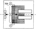
Then, will illustrate as the flattening device 700 that is used to push the folding spine portion of folded sheet bundle and makes the planarizing unit of its planarization with reference to figure 11A and 11B.Figure 11 A and 11B are the cross sectional drawing and the planar views of flattening device 700 shown in Figure 1.
Flattening device 700 receives by the bookbinding handling part of automatic collating unit 500 orders the thin slice bundle B that sews and fold, and by load-transfer device 701 this thin slice is transported to the downstream.When the thin slice bundle B on the conveying load-transfer device 701, the rear end of auxiliary part 710 auxiliary sheet bundle B.When the skin resistance of the bottom sheet of thin slice bundle B hour, prevent that thin slice bundle B from sliding on load-transfer device 701.
Hill holder (registration removing stopper) 708 is eliminated in the bevelled location that is provided for eliminating the thin slice bundle B that receives in the downstream of load-transfer device 701.Tilt to eliminate operation if finished, then hill holder 708 is eliminated around S. A. 708a rotation and return in the location, discharges conveying roller 702 thereby thin slice bundle B is delivered to.
Come clamping to proofread and correct bevelled thin slice bundle B by fixing lower gripper 707 and the vertically moving clamper 706 of going up by location elimination hill holder 708.
The location is eliminated hill holder 708 and can be moved along the thin slice throughput direction.Thin slice bundle B eliminates the overhang that the clamper of the relative folded sides of thin slice bundle B is adjusted in the elimination position, location of hill holder 708 along the clip position of throughput direction by adjusting the location.
Inboard by slave unit is used to carry out the crimping roller 709 of planarization and by pushing thin slice bundle B from the outstanding fold surface of clamper to preceding side shifting, comes planarization by the fixing thin slice bundle of lower gripper 707 and last clamper 706.
Then, by discharging conveying roller 702 thin slice bundle B is loaded on the loading pallet 720.Load-transfer device 721 is set on loading pallet 720, and carries thin slice bundle B and it is carried to the downstream.
When not carrying out planarization, eliminate hill holder 708 by the location and eliminate inclination, and thin slice is discharged to loading pallet 720 and does not carry out planarization by crimping roller 709.When not carrying out planarization, eliminate inclination when automatic collating unit 500 is delivered to flattening device 700 equally, thereby strengthen the alignment of thin slice bundle on the loading pallet 720 at the thin slice bundle that thin slice is produced.
The block diagram of flattening device
Then, will the structure that drive and control the planarization control setup 971 of flattening device 700 be described with reference to Figure 12.Figure 12 is the block diagram that the structure of the planarization control setup 971 shown in Fig. 2 is shown.
As shown in Figure 12, planarization control setup 971 comprises CPU972, ROM973 and RAM974.Planarization control setup 971 is communicated by letter and swap data between them with the automatic collating unit control setup 951 that is arranged on automatic collating unit 500 sides by communication IC (not shown), carry out the various programs that are stored among the ROM973 based on instruction, and drive and control flattening device 700 from automatic collating unit control setup 951.
About various input and output, be provided with the band motor M20 that is used to drive load-transfer device 701, be used to the clamping motor M22 that drives the servo-motor M21 of auxiliary part 710 and be used for clamper 706 on the vertical drive.In addition, be provided with the planarization motor M23 that is used to drive crimping roller 709, be used to drive discharge motor M24 that discharges conveying roller 702 and the conveying motor M25 that is used to drive load-transfer device 721.Also be provided with as inlet sensor 703, alignment sensor 704, discharge the incoming signal that passes through that sensor 705 and feeding sensor 725 etc. are used to detect thin slice.
The flow process of planarization operation
The flow process of planarization operation then will be described.Figure 13 to 16 is cross sectional drawing and the planar views that are used to illustrate the planarization operation.
As shown in Figure 13 A and the 13B, the thin slice bundle B after folding is delivered to load-transfer device 701 as benchmark from automatic collating unit 500 with the center of the horizontal direction of thin slice.At this moment, last clamper 706 is in the raised position standby, and lower gripper 707 and last clamper 706 are in open mode.The location is eliminated hill holder 708 and has been moved to elimination position, location and be in standby.Auxiliary part 710 returns to the position standby of downside at the belt surface from load-transfer device 701 contact thin slice bundle B.If carrying and detect the rear end of thin slice bundle B, load-transfer device 701 passed through inlet sensor 703, then with the constant speed drive auxiliary part 710 of load-transfer device 701, load-transfer device 701 moves to extrusion position, and auxiliary part 710 moves to follow the rear end of thin slice bundle B.
As shown in Figure 14 A and the 14B, by the rear end that load-transfer device 701 is carried thin slice bundle B and promoted thin slice bundle B by auxiliary part 710, thin slice bundle B eliminates hill holder 708 and eliminates its inclination against the location.Then, stop load-transfer device 701 and auxiliary part 710, last clamper 706 reduces, and fixes this thin slice bundle B.
Then, as shown in Figure 15 A and the 15B,, locate elimination hill holder 708 and keep out of the way for the mobile crimping roller 709 in ridge surface along thin slice bundle B.Crimping roller 709 crimping are from the fold surface of the outstanding thin slice bundle B of lower gripper 707 and last clamper 706, and the inboard of slave unit moves to the front side, move by side to the inboard more in the past, thereby carry out planarization.
Then,,, then move up and go up clamper 706, drive load-transfer device 701 and auxiliary part 710, and thin slice bundle B is transported to the downstream to remove clamping to thin slice bundle B if finished planarization as shown in Figure 16 A and the 16B.Simultaneously, also driving is discharged conveying roller 702 and this thin slice bundle B is discharged to loading pallet 720.If arriving, the front end of thin slice bundle B discharges conveying roller 702, then auxiliary part 710 stops to drive downstream this thin slice bundle B, this auxiliary part 710 of reverse drive and this auxiliary part 710 turn back to the position of readiness shown in Figure 13, and can receive next thin slice bundle.
The setting of stapling mode
Then, the flow process of the setting of stapling mode will be described with reference to Figure 17 to 19.
If selected the soft key " application model " on the initial picture shown in Fig. 3, then liquid crystal display part 420 switches to the picture of selection various patterns as shown in figure 17.Here, if selected " bookbinding ", then as shown in figure 18, demonstration can select to accommodate the key of the box of the record sheet that will export.Here, if selected to accommodate the size that will use thin slice box and supress " next step " soft key, then as shown in figure 19, show the picture that is used to be provided with to the processing of bookbinding thin slice bundle.
If selected stapling mode, then carry out folding operation at least, but the user can select whether should order and sews operation, and select one of " order and sew " and " do not order and sew ".
Also provide planarization that portion is set, made that the user can select whether should carry out planarization.According to the picture that is provided with shown in Figure 19, select one of " carrying out planarization " and " not carrying out planarization ", whether should carry out planarization with decision.
Then, if supress " OK ", then be provided with and finish, picture turns back to initial picture, presses initiating key 402, and the user waits for till beginning operation.
Folding operation according to stapling mode
Then, the folding processing that explanation is carried out according to the pattern that is provided with in stapling mode by the bookbinding handling part.
Carry out clamping by folding roller to 556, carry out the folding operation under the stapling mode by automatic collating unit 500.As shown in Figure 20, folding roller comprises folding roller 556a down to 556, and this time folding roller 556a anchor shaft.Last folding roller 556b makes the downward folding roller 556a of roll shaft (downwards) skew by spring 580.This be because, as shown in Figure 21, go up the position (dotted line) of the initial crimping of folding roller 556b relatively, folding roller can be pushed the thickness of the bookbinding thin slice bundle between 556 the roll gap and moves up 556 according to entering into folding roller.
Provide and be used to switch as the folding roller of folding means switching part to the clamp pressure of 556 pairs of thin slice bundles.As shown in Figure 20, this switching part have can vertical shifting, the arm 581 of the S. A. of folding roller 556b in the support, and come vertical shifting arm 581 and can fix this arm 581 by separating motor M13.
In the present embodiment, switching part switches between crimped status and released state, and wherein, under crimped status, folding roller is to 556 crimping, and under released state, folding roller is to 556 preset distances separated from each other.
When having selected " not carrying out planarization " in being provided with of stapling mode shown in Figure 19, folding roller 556a and 556b are in crimped status up and down, make folding roller obtain the maximum folded pressure to 556.Enter between the roll gap if bind the thin slice bundle in this state, then fold processing under the maximum folded pressure status having applied.
If selected " carrying out planarization " under the stapling mode in Figure 19, then as shown in figure 22, move up and support the arm 581 of the roll shaft of going up folding roller 556b by drive separating motor M13.In this state, following folding roller 556a does not contact each other with last folding roller 556b, and the two is separated from each other in this state, and this disengaged position is defined as initial position, and no longer reduces the distance between these rollers.As shown in Figure 23, in this initial position (long and short dash line) the thin slice Shu Jinhang that is contained in the bookbinding processing pallet 560 is folded processing.At this moment, the thin slice bundle enters between the roll gap of the 556a of folding roller up and down of separation and 556b, and comes folding roller 556b on the vertical shifting according to the thickness of thin slice bundle by spring 580.
To 556 crimping and separating treatment, as shown in the diagram of circuit in Figure 24, whenever folding when handling, judging whether should be to thin slice Shu Jinhang to be processed planarization (S1000) about folding roller.When not carrying out planarization, this processing enters step S1001, and the judgement folding roller is to 556 current state.If folding roller is to being in crimped status in step S1001, then this is finished dealing with and is not driven separation motor M13.
Crimping sensor (not shown) detect to be gone up the position of folding roller 556b, and can judge that whether folding roller to being in contact condition according to the position of last folding roller 556b.If the crimping sensor is opened, then this state is a crimped status, and if the crimping sensor close, then this state is not a crimped status.
When in step S1001, being judged as this state when being not crimped status, being rotated in the forward and driving and separate motor M13.Utilize this operation, begin blocked operation (S1002) to crimped status, and if the unlatching of crimping sensor, then be judged as folding roller 556b and arrive crimping position (S1003), and stop to drive separation motor M13 (S1004).
When being judged as in step S1000 should carry out planarization the time, process enters step S1010, and judges whether folding roller is released state to 556 current state.Be in released state if be judged as folding roller to 556, then do not drive separation motor M13 and process and finish.
Can determine to go up the position of folding roller 556b by the separation sensor (not shown), whether carry out about state is the judgement of released state, and if the separation sensor unlatching, then this state is a released state, if and this separation sensor cuts out, then this state is not a released state.
If be judged as this state in step S1010 is not released state, and then contrarotation and driving separate motor M13, and begin the switching (S1011) to released state.If separation sensor is opened, then be judged as folding roller 556b and arrive disengaged position (being "Yes" among the S1012), and stop to drive separation motor M13 (S1013).
When having selected " carrying out planarization ", because folding roller is separated from one another to 556, so folding roller is low to the folding pressure of folding pressure ratio when having selected " not carrying out planarization " of 556 pairs of thin slice bundles.Because the difference of folding pressure, thereby the shape (Figure 21) on folding ridge surface is different with the shape (Figure 23) on folding ridge surface when having selected " carrying out planarization " and folding roller to be separated from each other 556 when having selected " not carrying out planarization " and folding roller to 556 crimping.
In the present embodiment, bookbinding thin slice bundle is provided with front cover, and forms image on the spine part.When spine is partly carried out planarization, owing to fold pressure less than the folding pressure when not carrying out planarization, so the image on the spine can not break.
Although in the present embodiment, folding roller to 556 two positions, be to switch between crimping position and the disengaged position, but when having selected " carrying out planarization ", can in a plurality of stages, switch disengaged position according to the thin slice quantity that is contained in a thin slice bundle in the bookbinding processing pallet.At this moment, can measure and be contained in the thickness that a thin slice bundle in the pallet is handled in bookbinding, and can switch folding roller according to the thickness of this thin slice bundle a plurality of disengaged positions of 556.Utilize this operation, can clamp pressure be set according to the thickness of thin slice bundle, and can eliminate the lip-deep situation that folding line is retained in spine effectively.Can be provided with according to the thickness of thin slice quantity or thin slice bundle in the structure of clamp pressure, can switch the clamp pressure of the thin slice of the thin slice of equal number and same thickness according to whether carrying out " planarization ".
Although binding device can be ordered and sew and fold, only have folding operation and do not have and order the binding device of sewing operation and also can carry out planarization.As the method that is used for binding one by one thin slice, stick with glue or traditional thread binding except that ordering to make sewing.
Although the present invention has been described with reference to exemplary embodiments, should be appreciated that, the invention is not restricted to disclosed exemplary embodiments.The scope of appended claims meets the wideest explanation, to comprise all this class modification and equivalent structure and functions.
The application requires the preceence of Japanese patent application 2007-273658 that submitted on October 22nd, 2007 and the Japanese patent application 2008-255882 that submitted on October 1st, 2008, and the full content of this application is incorporated this paper into by reference at this.
Claims (6)
1. sheet processing apparatus comprises:
Folding means is used for clamping and folded sheet bundle;
Planarizing unit is used to push by described folding means the folding spine portion of the described thin slice bundle after folding, thereby makes described folding spine portion planarization; And
Switching part is used to switch the clamp pressure of described folding means to described thin slice bundle,
It is characterized in that described switching part switches, feasible described clamp pressure when being provided with planarization is less than the described clamp pressure when described planarization is not set.
2. sheet processing apparatus according to claim 1 is characterized in that,
Described folding means roller between the described thin slice bundle of clamping; And
Described switching part can change described roller between distance.
3. sheet processing apparatus according to claim 1 is characterized in that,
The described thin slice bundle that is folded is provided with front cover.
4. sheet processing apparatus according to claim 1 is characterized in that,
When being provided with described planarization, described switching part can switch the described clamp pressure of described folding means to described thin slice bundle according to the intrafascicular thin slice quantity of described thin slice.
5. sheet processing apparatus according to claim 1 is characterized in that,
When being provided with described planarization, described switching part can switch the described clamp pressure of described folding means to described thin slice bundle according to the thickness of described thin slice bundle.
6. image forming apparatus comprises:
Image forming part is used for forming image on thin slice; And
According to each described sheet processing apparatus in the claim 1 to 5, the described sheet fold that is used for having formed image by described image forming part becomes two parts, and makes described thin slice planarization.
Applications Claiming Priority (6)
| Application Number | Priority Date | Filing Date | Title |
|---|---|---|---|
| JP2007-273658 | 2007-10-22 | ||
| JP2007273658 | 2007-10-22 | ||
| JP2007273658 | 2007-10-22 | ||
| JP2008-255882 | 2008-10-01 | ||
| JP2008255882 | 2008-10-01 | ||
| JP2008255882A JP5147627B2 (en) | 2007-10-22 | 2008-10-01 | Sheet processing apparatus and image forming apparatus |
Publications (2)
| Publication Number | Publication Date |
|---|---|
| CN101417759A CN101417759A (en) | 2009-04-29 |
| CN101417759B true CN101417759B (en) | 2011-06-15 |
Family
ID=40628790
Family Applications (1)
| Application Number | Title | Priority Date | Filing Date |
|---|---|---|---|
| CN2008101673499A Expired - Fee Related CN101417759B (en) | 2007-10-22 | 2008-10-22 | Sheet processing apparatus and image forming apparatus |
Country Status (3)
| Country | Link |
|---|---|
| JP (1) | JP5147627B2 (en) |
| CN (1) | CN101417759B (en) |
| DE (1) | DE602008001935D1 (en) |
Families Citing this family (12)
| Publication number | Priority date | Publication date | Assignee | Title |
|---|---|---|---|---|
| JP4775371B2 (en) * | 2007-12-21 | 2011-09-21 | 富士ゼロックス株式会社 | Paper processing device |
| JP5533486B2 (en) * | 2009-06-09 | 2014-06-25 | 株式会社リコー | Back surface forming apparatus, sheet processing apparatus, and image forming system |
| JP4598151B1 (en) * | 2009-06-09 | 2010-12-15 | 株式会社リコー | Back surface forming apparatus, sheet processing apparatus, image forming system, and back surface forming method |
| JP4977771B2 (en) * | 2009-10-16 | 2012-07-18 | 株式会社リコー | Bookbinding system |
| JP5631172B2 (en) * | 2009-12-16 | 2014-11-26 | キヤノン株式会社 | Sheet processing apparatus and image forming apparatus |
| JP5769491B2 (en) * | 2010-05-18 | 2015-08-26 | キヤノン株式会社 | Sheet processing apparatus, image forming apparatus, and sheet buffer apparatus |
| JP5477251B2 (en) * | 2010-10-08 | 2014-04-23 | 株式会社リコー | Booklet processing apparatus, image forming system, and booklet processing method |
| JP5500156B2 (en) | 2011-11-22 | 2014-05-21 | コニカミノルタ株式会社 | Post-processing method and post-processing apparatus |
| JP5870662B2 (en) * | 2011-12-07 | 2016-03-01 | コニカミノルタ株式会社 | Post-processing apparatus and image forming system |
| JP5846028B2 (en) * | 2012-04-18 | 2016-01-20 | コニカミノルタ株式会社 | Paper processing apparatus and paper processing method |
| KR101924680B1 (en) * | 2012-11-07 | 2019-02-20 | 유니바인드 리미티드 | Method for binding a bundle of leaves, a bundle of leaves, method and device for forming such a bundle of leaves |
| JP5776720B2 (en) * | 2013-04-11 | 2015-09-09 | コニカミノルタ株式会社 | Post-processing apparatus and image forming system |
-
2008
- 2008-10-01 JP JP2008255882A patent/JP5147627B2/en not_active Expired - Fee Related
- 2008-10-21 DE DE200860001935 patent/DE602008001935D1/en active Active
- 2008-10-22 CN CN2008101673499A patent/CN101417759B/en not_active Expired - Fee Related
Also Published As
| Publication number | Publication date |
|---|---|
| JP5147627B2 (en) | 2013-02-20 |
| JP2009120398A (en) | 2009-06-04 |
| CN101417759A (en) | 2009-04-29 |
| DE602008001935D1 (en) | 2010-09-09 |
Similar Documents
| Publication | Publication Date | Title |
|---|---|---|
| CN101417759B (en) | Sheet processing apparatus and image forming apparatus | |
| US7192020B2 (en) | Sheet processing apparatus for storing supplied sheets while preceding sheet are processed | |
| EP2053004B1 (en) | Sheet processing apparatus and image forming apparatus | |
| US6546226B2 (en) | Image forming apparatus, sheet processing apparatus, sheet processing method, and book-binding method | |
| US8556249B2 (en) | Image forming apparatus that supplies sheet on which image is formed to ring bookbinding apparatus | |
| US8905394B2 (en) | Sheet post-processing apparatus with an alignment-side determination feature | |
| US7926800B2 (en) | Sheet processing apparatus and image forming apparatus | |
| JP2765654B2 (en) | Sheet binding device | |
| US8155576B2 (en) | Sheet processing apparatus and image forming apparatus | |
| JP5197237B2 (en) | Sheet processing apparatus and image forming apparatus | |
| JP3130507B2 (en) | Image forming apparatus having 2 in 1 mode | |
| JP2009101439A (en) | Cutting device, sheet processor, and image forming device | |
| JP3115643B2 (en) | Image forming system | |
| JP5522922B2 (en) | Sheet conveying apparatus, sheet processing apparatus, and image forming apparatus | |
| JP2008297036A (en) | Sheet processing device and image forming device having the same | |
| JP5546652B2 (en) | Image forming system and image forming apparatus | |
| JP2004035228A (en) | Sheet conveyance device and image forming system | |
| JP2000211803A (en) | Image forming device and book-making method | |
| JP3149273B2 (en) | Image forming device | |
| JP2003300664A (en) | Sheet post-processing apparatus and image forming apparatus | |
| JP2003160272A (en) | Image forming device | |
| JP2002205297A (en) | Sheet after-treatment device and image forming device | |
| JP2004345810A (en) | Method and device for measuring sheet thickness, and sheet processing device | |
| JP2004035227A (en) | Sheet conveyance device and image forming system | |
| JP2003002526A (en) | Image forming device and after-treatment control method of image forming device |
Legal Events
| Date | Code | Title | Description |
|---|---|---|---|
| C06 | Publication | ||
| PB01 | Publication | ||
| C10 | Entry into substantive examination | ||
| SE01 | Entry into force of request for substantive examination | ||
| C14 | Grant of patent or utility model | ||
| GR01 | Patent grant | ||
| CF01 | Termination of patent right due to non-payment of annual fee | ||
| CF01 | Termination of patent right due to non-payment of annual fee |
Granted publication date: 20110615 Termination date: 20181022 |