CN101409725A - Information processing apparatus and control method therefor - Google Patents
Information processing apparatus and control method therefor Download PDFInfo
- Publication number
- CN101409725A CN101409725A CNA2008101689849A CN200810168984A CN101409725A CN 101409725 A CN101409725 A CN 101409725A CN A2008101689849 A CNA2008101689849 A CN A2008101689849A CN 200810168984 A CN200810168984 A CN 200810168984A CN 101409725 A CN101409725 A CN 101409725A
- Authority
- CN
- China
- Prior art keywords
- information
- printer
- image forming
- installation modes
- installation
- Prior art date
- Legal status (The legal status is an assumption and is not a legal conclusion. Google has not performed a legal analysis and makes no representation as to the accuracy of the status listed.)
- Pending
Links
Images


Classifications
-
- G—PHYSICS
- G06—COMPUTING; CALCULATING OR COUNTING
- G06F—ELECTRIC DIGITAL DATA PROCESSING
- G06F8/00—Arrangements for software engineering
- G06F8/60—Software deployment
- G06F8/61—Installation
-
- G—PHYSICS
- G06—COMPUTING; CALCULATING OR COUNTING
- G06F—ELECTRIC DIGITAL DATA PROCESSING
- G06F9/00—Arrangements for program control, e.g. control units
- G06F9/06—Arrangements for program control, e.g. control units using stored programs, i.e. using an internal store of processing equipment to receive or retain programs
- G06F9/44—Arrangements for executing specific programs
- G06F9/4401—Bootstrapping
- G06F9/4411—Configuring for operating with peripheral devices; Loading of device drivers
Abstract
If a device driver is simply installed in the same manner for any network environment, there is a possibility that the device driver is installed in a manner improper for a particular network environment. To avoid the above problem, an information processing apparatus selects an optimum installation mode according to property information of the information processing apparatus and property information of an image forming apparatus.
Description
Technical field
The present invention relates to a kind of messaging device and control method.
Background technology
Recent years, realized the improvement of the foundation structure that is associated with network.This caused such as printer, photocopier, facsimile machine, scanner, digital camera, have a plurality of functions MFP (multi-function peripheral) but etc. various types of other network connection or being extensive use of of network connection device.Hereinafter, these equipment generally will be called peripheral unit/equipment.Correspondingly, develop various technology and be used for user's operation or the internal control that messaging device installation network connect/can connect the driver of ancillary equipment.Especially, use network to become universal at home.Network environment can mainly be categorized as three groups: home network environment, office network environment and commons network environment.
Figure 27 comparatively illustrates the tabulation of three kinds of network environments (be home network environment, office network environment, and commons network environment).In this tabulation shown in Figure 27, " family expenses (home) " row are described the feature of home network environment, and " (office) used in office " row are described the feature of office network environment, and the feature of " commons (public) " row description commons network environment.The example of commons network environment be on the airport, those environment of eating house etc.In the row of tabulation, every feature with the indication respective environment is described.More particularly, in the crossing field of " type of device/PC " and row " family expenses " of being expert at, being described to the periphery of using in the family expenses network environment or the type of messaging device is television set, game machine, DVD player, information equipment and MFP (multi-function peripheral).In the crossing field of " type of device/PC " and row " office with " of being expert at, being described in the device type of using in the office network environment is messaging device and MFP.Be expert at " quantity of PC " with row " family expenses " crossing field in, the quantity that is described in the messaging device that uses in the home network environment is 1 to 5.On the other hand, in the office network environment, use 20 to 200 equipment.Be expert at " quantity of device " and be listed as in the crossing field of " family expenses ", the quantity that is described in the ancillary equipment that uses in the home network environment is 2 to 8.On the other hand, in the office network environment, use 5 to 10 ancillary equipment.For example, a printer that is used as one of ancillary equipment in the family expenses network environment can be shared by all messaging devices in this home network environment.
On the other hand, in the office network environment, two to four or more printer are shared (for example, sharing a printer in each department) according to the requirement in the department of office or zone or according to application target by a plurality of messaging devices.
In the family expenses network environment, network is managed or maintenance by someone (as the father of family) in the family as described in be expert at " custodian (Maintained by) ".On the other hand, in the office network environment, network is by network manager's management or maintenance.
In public places, environment may be a various forms, thereby does not specify quantity (" quantity of PC "), and the quantity (" quantity of device ") of ancillary equipment of type (" type of device/PC "), the messaging device of ancillary equipment or messaging device.In the commons network environment, network does not have third party's management of particular kind of relationship by the user with network environment or safeguards.
Some nearest messaging device has the Microsoft WindowsVista (registered trade mark) that is installed in wherein as OS (operating system).
Ancillary equipment can be categorized into two types: be used in the high-performance printer in the office, as have the laser printer or the photocopier of network communications capability; And have network communications capability, its performance and office with the printer low household printer (as ink-jet printer) of comparing.
For the messaging device that uses printer is set, in other words, for printed driver is installed in the messaging device, the user must carry out fitting operation.Typical fitting operation is as follows.
The icon of printer is represented in step 4. user right click in network folder, and selects " installation " menu.
The order of the driver of installing peripherals in messaging device (as printer) is carried out in a similar manner, and no matter ancillary equipment is to handle official business with printer or household printer.In installation, " plug and play expansion (PnP-X) " function or " about the Web service of device " (WSD) function can be used on request.These two functions are included among Windows (registered trade mark) the Vista OS (operating system) as standard feature.WSD be equivalent to through the Internet from W3C (
Http:// www.w3.org) available " being used for the device configuration of Web service ".PnP-X is the expansion of " plug and play ", and its network enabled jockey.
The open No.2007-066091 of Japan Patent discloses a kind of technology of automatic install driver.In this technology, according to the network environment that messaging device connected, make about whether should the erecting device driver determine.
In the conventional mounting technique, the driver of ancillary equipment (printer) is installed in the messaging device through user's operation in a similar manner, and tape/tube printer is not to handle official business with printer or household printer.The user is provided with office with under the situation of printer in the office network environment of management such as skilled network manager, the user correctly is provided with printer by operation easily under skilled network manager's instruction.
Yet in the home network environment that the skilled person who can't help such as the network manager manages, the user is not easy correctly to install.Thereby, failure is installed usually takes place.If failure is installed, then can not uses ancillary equipment.
A kind of technology that overcomes the above problems is to make the installation automation.Yet,, be used under the "on" position and the device driver that is connected to all printers of network is installed under the "on" position and is connected to all messaging devices of network if office is provided with simply automatically with printer.As a result, the user may be installed and not want the printed driver installed.
Summary of the invention
In view of more than, the invention provides a kind of method that ancillary equipment is set in the best way according to the environment that uses ancillary equipment.
More specifically, the invention provides a kind of messaging device that can communicate by letter with image forming apparatus, comprising: setup unit is configured to set first attribute information of the installation site of indication information treatment facility (1); And selected cell, be configured to select Installation Modes, thereby when first attribute information of setup unit setting is indicated first installation site, selected cell is selected automatic Installation Modes, wherein the device driver of image forming apparatus is installed automatically and is not accepted the installation order that the user sends, and when first attribute information of setup unit setting was indicated second installation site, selected cell was selected manual Installation Modes, wherein the installation order erecting device driver that sends according to the user.
Further feature of the present invention is apparent by the following description of the example embodiment of reference accompanying drawing.
Description of drawings
Fig. 1 is a calcspar, and the peripheral unit control system that comprises messaging device and ancillary equipment according to the embodiment of the invention is shown.
Fig. 2 is a calcspar, and the example of the hardware construction of PC is shown.
Fig. 3 is a calcspar, and the hardware construction of printer is shown.
Fig. 4 illustrates the software construction of PC.
Fig. 5 illustrates the structure of the printed driver of PC.
The position that Fig. 6 illustrates the position that is used for being provided with PC is provided with dialog box.
Fig. 7 illustrates the network monitoring program.
Fig. 8 illustrates the network monitoring program.
Fig. 9 illustrates the N-PnP information that printer sends.
Figure 10 A and 10B are meant and are shown in the form that concerns between PC position, network discovery function and the peripheral unit Installation Modes.
Figure 11 is used to determine the form that is controlled at the pattern of display message on the network monitoring program and the pattern of peripheral unit is set.
Figure 12 is a flow chart, and the example of the process that peripheral unit is set is shown.
Figure 13 is a flow chart, is illustrated in the checking process in the automatic installation.
Figure 14 is a flow chart, and the example of the process that peripheral unit is set is shown.
Figure 15 is a flow chart, and the autoinstall procedure that uses password code (passcode) is shown.
Figure 16 illustrates the screen of the position that is used for being provided with peripheral unit.
Figure 17 illustrates the screen of the password code that is used for being provided with peripheral unit.
Figure 18 illustrates the password code information of being sent by PC.
Figure 19 illustrates the password code confirmation that printer sends.
Figure 20 illustrates the network monitoring program.
Figure 21 illustrates printers.
Figure 22 illustrates IHV network monitoring program.
Figure 23 illustrates IHV network monitoring program.
Figure 24 is the pattern and the form that the pattern of peripheral unit is set that is used to determine to be controlled at display message on the IHV network monitoring program.
Figure 25 illustrates the information that is associated with WS-Discovery.
Figure 26 illustrates the memory mapping figure of storage medium, store various kinds of data handling procedure in storage medium, thus they can be read according to the peripheral unit control system of the embodiment of the invention.
Figure 27 is the tabulation that three kinds of network environments are shown: promptly, and home network environment, office network environment, and commons network environment.
Figure 28 illustrates the process flow diagram of selecting Installation Modes.
Figure 29 is a flow chart, and the process of selecting Installation Modes is shown.
Figure 30 illustrates the network monitoring program.
Figure 31 illustrates device and confirms dialog box.
Embodiment
In the description below, the description of SOAP (Simple Object Access Protocol) is omitted because its description can be on the internet W3C (
Http:// www.w3.org) find.Notice that the explanation that provides in the following description about Windows (registered trade mark) Vista OS (operating system) is based on http://msdn.microsoft.com/library/default.asp on the Internet) available information (according on August 21st, 2007).
First exemplary embodiment
Fig. 1 is a calcspar, and the print system that comprises messaging device and the ancillary equipment (being also referred to as image forming apparatus) that is connected to messaging device of being used to communicate by letter according to the embodiment of the invention is shown.
In Fig. 1, Reference numeral 1 indication information treatment facility.With regard to messaging device 1, can use the personal computer (hereinafter referred is PC) of common type.PC 1 disposes hardware in mode shown in Figure 2, and the OS (operating system) that has such as Microsoft Windows Vista (registered trade mark) is installed in wherein.PC 1 receives network 4 based on Ethernet (registered trade mark) technical battery.
The application program that Reference numeral 80 and 81 indication PC 1 carry out.Application program 80 and 81 can provide with the form of the last executable file of Windows (registered trade mark) OS (* .EXE).More particularly, in the present embodiment, for example suppose that application program 80 and 81 is network monitoring programs those shown in Fig. 7 or 22.
Fig. 2 is a calcspar, and the hardware construction example of PC is shown.As shown in the figure, PC 1 comprise random access memory (RAM 1201), as the hard disk drive (HDD1202) of memory cell and as the keyboard (KBD 1203) of input unit.PC 1 also comprises CPU 1204, the display (LCD 1205) as control unit and is used as the network board (NB1207) of communication controler.NB 1207 allows PC 1 to communicate by letter with image forming apparatus.In PC 1, parts 1201 to 1205 and 1207 are connected to each other through bus 1206.Memory cell is not limited to hard disk drive, but other device such as removable CD-ROM device or built-in ROM device can be used as memory cell.Module shown in Fig. 4 or 5 (software) is stored among the HDD 1202, and reads in RAM 1201 on request and carried out by CPU 1204.
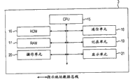
Fig. 3 is a calcspar, and the hardware construction of printer is shown.Printer 3 and 5 has and the similar hardware construction of structure shown in Figure 3 separately.In the following description, for example printer 3 is given an explaination.
In Fig. 3, the CPU that Reference numeral 15 indication use microprocessors etc. are implemented.In printer 3, CPU 15 is as the CPU of being responsible for according to ROM 16 program stored control RAM 17, communication unit 18, register 19, operating unit 20 and display.In ROM 16, program is stored, thus printer 3 carry out program stored wherein with write down (printing) process, other process under the control of the process of the state notifying PC 1 of printer 3 or printed driver 50 (describing) below with reference to Fig. 5.RAM 17 is mainly used to the print data that interim storage receives and used by register 19 from PC 1 printer operation.Communication unit 18 has port, through it printer 3 is connected to network 4, and communication unit 18 control ethernet communications.Register 19 comprises record cell, and record cell comprises ink jet print head, colored ink, carriage and paper delivering mechanism.Register 19 also comprises the circuit that uses ASIC etc. to implement, and this circuit is used for producing according to print data the print pulse of recording head.
Print with the application program with print capacity if the user gives an order, the view data of the file that application program is opened is stored as the spool file of EMF form (strengthening the meta file form) temporarily in the HDD 1202 of PC 1.The spool file of storage converts the print data that comprises the printer control command that is used for controlling printer 3 to through printed driver 50.The print data that generates sends to printer 3 through network 4.In printer 3, the print data of reception converts print pulse to by register 19, and is printed on the printing paper.Reference numeral 20 indication operating units, it comprises and is used for the various buttons such as power knob and reset button of printer operation 3.The display that Reference numeral 21 indication uses LCD with touch panel to implement, touch panel is suitable for showing the state of printer 3, and also is used for input and show the various parameters that are provided with.Note, in the present embodiment, for example but be not to suppose that restrictedly printer 3 is ink-jet types.
Fig. 4 illustrates the software construction of PC.In the figure, the Ethernet control storehouse of Reference numeral 92 indication control Ethernets.Reference numeral 91 indications are suitable for controlling the IP network control storehouse of IP network.Reference numeral 90 indications are suitable for controlling the WSD control storehouse of WSD function.Reference numeral 89 indications are suitable for controlling this machine of IHV agreement control storehouse of IHV-specialized protocol.Reference numeral 88 indications are suitable for the N-PnP control storehouse of the plug-and-play feature (hereinafter referred is the N-PnP function) of Control Network.Notice that Windows Vista OS comprises that " the plug and play expansion " of supporting the processing network connection device is (PnP-X) as standard feature.In the present embodiment, suppose and use and the similar N-PnP function of PnP-X.Reference numeral 85 indicating device drivers, device driver comprise one group of IHV driver 86 that one group of standard driver 87 comprising as standard and IHV (separate hardware manufacturer) provide in OS.Reference numeral 84 indications comprise application program/DDI interface of API (application programming interface) and DDI (device driver interface).Reference numeral 80 indication application programs.More particularly, in the present embodiment, application program 80 is the network monitoring programs that comprise in OS as standard.Reference numeral 81 indication Another Application programs.More particularly, in the present embodiment, application program 81 is network monitoring programs that IHV provides.Hereinafter, application program 80 will be called network monitoring program 80, and application program 81 will be called IHV network monitoring program 81.Reference numeral 30 indications have the capable application of sending print command, will describe this print command below with reference to Fig. 5.Reference numeral 82 indications comprise the total collection of the application program of network monitoring program 80, IHV network monitoring program 81 and application program 30.The WS-Discovery incident be will describe below with reference to Figure 12,14 and 25 and network monitoring program 80 and IHV network monitoring program 81 will be notified to through application program/DDI interface 84.Network monitoring program 80 and IHV network monitoring program 81 can be obtained the details of describing about printer 3, information as shown in Figure 9 through application program/DDI interface 84 in associated metadata elements 107.Network monitoring program 80 is through application program/DDI interface 84, as following with reference to Fig. 7, Fig. 8 and Figure 20 will as described in, display icon 42, icon 43, icon 44 and choice box 45 are to specify the automatic installation that whether allows legacy devices.In addition, network monitoring program 80 shows through application program/DDI interface 84 installs menu 51, web page interlinkage menu 52, attribute display menu 53 and unloading menu 79.
IHV network monitoring program 81 is through application program/DDI interface 84, as following with reference to Figure 22 and 23 will as described in, display icon 100, icon 101 and icon 102.In addition, IHV network monitoring program 81 shows installation menu 103, web page interlinkage menu 104, attribute display menu and unloading menu 106 through application program/DDI interface 84.Network monitoring program 80 and IHV network monitoring program 81 can through application program/DDI interface 84 printed driver 50 that is used for printer 3 is installed in PC 1 and it from PC 1 unloading.IHV network monitoring program 81 can be through application program/DDI interface 84 the password code message transmission to printer 3 or obtain affirmation result's the information of indication password code.The example of password code information will be described below with reference to Figure 18, and the example of password code confirmation will be described below with reference to Figure 19.
Fig. 5 illustrates the configuration of the printed driver of PC.In the figure, Reference numeral 50 indications are used for the printed driver of printer 3.Printed driver 50 is installed among the PC1.Printed driver 50 comprises a plurality of modules 33 to 38.
Reference numeral 37 is indicated the port monitoring programs, and 38 transfer of data that receive from The Monitor Model program 36 of its process class driver are to proper port and receive the data of transmitting from printer 3.Class driver 38 is and the immediate lower-level modules of port.
In an embodiment of the present invention, printed driver is corresponding to other driver of printer class of WSD agreement or IHV agreement, and control port (network port in the present embodiment).In the present example, suppose that printed driver 50 is the available programs of company ABC of manufacturer from printer 3.
Fig. 6 illustrates the position dialog box 46 is set, and allows the user that the position of PC is set.Second attribute information that the position is set of indication PC 1 is to be provided with according to the configuration information that position shown in Figure 6 is provided with dialog box 46 input.What the user used that position shown in Figure 6 is provided with dialog box 46 definition PC 1 is provided with position (indicating the defined information that the position is set to be called second attribute information).More particularly, the user use location is provided with dialog box 46 and reaches from " family expenses ", " office is used " " commons " chosen position, the network environment of PC 1 is used in definition thus.
Selector button " is not specified " in Reference numeral 77 indications.If press this button, then the position of PC 1 is set to " not specifying ", and is provided with so that the network environment that the use of optional position is optimized is provided for PC 1.
Fig. 7 illustrates network monitoring program 80.As shown in Figure 7, PC and the ancillary equipment that is positioned at network 4 is presented at network monitoring program 80.Network monitoring program 80 is provided as the standard part of OS.
In Fig. 7, the icon of PC 1 is represented in Reference numeral 42 indications.The icon of printer 3 is represented in Reference numeral 43 indications.The icon of printer 5 is represented in Reference numeral 44 indications.
Fig. 8 illustrates the network monitoring program 80 under another state.In the figure, if the user is by using manual icon 43 and the right click icon 43 of selecting to represent printer 3 of mouse, display menu 51,52 and 53 so.
If select menu 51 is installed, then the printed driver 50 that is used for printer 3 be installed in PC 1.If finish the installation of printed driver 50, then menu 51 is installed in deletion, and shows unloading menu 79 as following as described in Figure 20.Printer icon 94 is presented in the printers of describing below with reference to Figure 21 93 then, can be used for printing with indication printer 3.
Figure 21 illustrates printers.In the figure, the printers that shows on the Reference numeral 93 indication PC 1.In this file, show PC 1 spendable printer.In specific examples shown in Figure 21, printer 3 is presented in the printers, to indicate printer 3 under upstate.
Figure 20 illustrates network monitoring program 80.In the figure, if manual icon 43 and the right click icon 43 of selecting to represent printer 3 of user, display menu 79,52 and 53 so.Menu 52 is identical with shown in Figure 8 those with 53.Reference numeral 79 indication unloading menus.If select this menu, then be used for the printed driver 50 of printer 3 from PC 1 unloading.If finish the unloading of printer 3, then menu 51 is installed in deletion unloading menu 79 and demonstration.In addition, from printers 93 deletion printer icon 94, thereby it no longer shows wherein.
Figure 16 illustrates the screen of the position that is used for being provided with ancillary equipment.Use this position that screen is set, allow the user that first attribute information that the position is set of indication ancillary equipment is set.In Figure 16, the position that Reference numeral 60 indications show on the display 21 of printer 3 is provided with screen, and it allows the position (be also referred to as the environment for use of ancillary equipment or position be set) of user from following selection ancillary equipment:
" family expenses " that are used for family expenses ancillary equipment;
Be used to handle official business with " office with " of ancillary equipment;
Be used for the ancillary equipment that uses in public position " commons "; And
" nothing " that is used for the ancillary equipment that uses at assigned address not.
Note, during shipment ancillary equipment, can be in advance with the position associated attributes default setting of ancillary equipment.
In example shown in Figure 16, first attribute information is arranged to specify " family expenses ".
Figure 25 illustrates the information that is associated with WS-Discovery.If printer 3 is connected on the network 4 and connects, then information shown in Figure 25 is transferred to PC and the ancillary equipment that is positioned on the network from printer 3.
Fig. 9 illustrates the N-PnP information that printer sends.In the figure, the N-PnP name space of the various parameters of Reference numeral 78 demonstrative definition N-PnP.Reference numeral 107 indications comprise the associated metadata elements of the SOAP of the details that are associated with ancillary equipment (printer 3).Reference numeral 72 indication N-PnP device categorical data elements, the classification of N-PnP device categorical data element indication ancillary equipment.Here being used for the character string of definition device classification comprises Computer (computer), Cameras (video camera), Printers (printer), Scanners (scanner), Storage (storage device), FAX, MFP, Displays (display), Gaming (game machine) and Phones (phone).In example shown in Figure 9, the device classification of device categorical data element 72 indication ancillary equipment is " printers ".
The data element that Reference numeral 73 indications are described in order to define N-PnP position (being the position of ancillary equipment).Following character string allows to be used for specifying the N-PnP position.
" family expenses " that are used for family expenses ancillary equipment;
Be used to handle official business with " office with " of ancillary equipment;
Be used for the ancillary equipment that uses in public position " commons "; And
" nothing " that is used for the ancillary equipment that uses at assigned address not.
In example shown in Figure 9, the position of data element 73 indication ancillary equipment is " family expenses ".Reference numeral 74 designation data elements, this data element are designated as the URL of the website of downloading the IHV software-accessible.In data element 74, any url data is described with indication URL.In example shown in Figure 9, url data is described as indicating the website of placing the software that company ABC provides in data element 74.IHV software URL is optionally, and in data element 74 descriptor not.The N-PnP information of all information and so on as shown in Figure 9 sends to PC or the ancillary equipment that is positioned on the network 4 from printer 3.
Figure 10 A and 10B are meant the form that concerns between the pattern that is shown in PC position, network discovery function and installing peripherals.These forms are standard modules of OS.In these forms, shown in Figure 10 A and 10B, for each the PC location definition network discovery mode (wherein search network) and the device Installation Modes (wherein installing peripherals) of Fig. 6 selection.Find that at network " On " indication network discovery feature is activated in the row.When network discovery function is when opening (on), PC 1 searches for PC and ancillary equipment position on network 4, and shows detected PC and ancillary equipment on network monitoring program 80 or IHV network monitoring program 81.
Find that at network " Off " indication network discovery feature is disabled in the row.When network discovery function is when closing (off), PC 1 is search PC and ancillary equipment position on network 4, and thereby does not show PC and ancillary equipment on network monitoring program 80 or IHV network monitoring program 81.
The automatic installation of " Automatic (automatically) " indication permission printed driver etc. is installed in the row at device.In this case, when ancillary equipment is connected to network 4 and its power supply and is switched on, allow PC 1 driver of installing peripherals automatically.
The manual printed driver etc. of installing of installation order that " Manual (craft) " indication is sent according to the user is installed in the row at device.In this case, when the ancillary equipment such as printer 3 is connected on the network 4 and its power supply when being switched on, PC 1 shows installation menu 51 shown in Figure 8 or installation menu 103 shown in Figure 22.If the user imports installation order by hand, then be provided with.
Install in the row at device, the installation of " Unavailable (unavailable) " indication peripheral device drivers is disabled.In this case, when ancillary equipment is connected on the network 4 and its power supply when being switched on, thus the PC 1 control operation driver of installing peripherals not.Note, when the firewall functionality of OS is the form shown in the application drawing 10A when opening, and when the firewall functionality of OS is shutoff the form shown in the application drawing 10B.
Figure 11 illustrates the form that definition is controlled at the pattern of the pattern of display message on the network monitoring program 80 and installing peripherals.This form is one of module of network monitoring program 80, and is provided as the standard part of OS.
Note,, use form shown in Figure 11 when the firewall functionality of OS as the situation of Figure 10 B is when closing.In Figure 11, in " PC Location " row, describe the position (position is set) of the PC of Fig. 6 setting, and " npnp:Location " is the row of describing N-PnP position data element 73." Network Monitor (network monitoring program) " row are to describe about controlling the information of the pattern of information on the network monitoring program 80 shown in Figure 7.Notice that N-PnP position data element 73 is indicated the position that is provided with of ancillary equipment.In Figure 11, in " Install (installation) " row, describe information, and in " npnp:DeviceCategory " row, place N-PnP device categorical data element 72 about the pattern of installing peripherals." Remark (remarks) " are the remarks row.
Indication be controlled at display message on the network monitoring program 80 pattern " NetworkMonitor " row in, " Displayed (demonstration) " thus specified and shown that controlled ancillary equipment is presented on the network monitoring program 80, and " Not Displayed (not showing) " specified ancillary equipment not to be presented on the network monitoring program 80.For example, be set under the situation of " Public (commons) " in the position that the position of PC 1 is set to the N-PnP information indication printer 3 that " Home (family expenses) " and printer 3 send, according to form shown in Figure 11, PC 1 does not show the icon of printer 3 on network monitoring program 80 so.
In " Install " row of indication ancillary equipment Installation Modes, " Auto (automatically) " specified and is provided with by automatic Installation Modes, and " Manual " appointment is provided with by manual Installation Modes.For example, be set under the situation of " Home (family expenses) " in the position that the position of PC 1 is set to the N-PnP information indication printer 3 that " Office (office with) " and printer 3 send, so, according to form shown in Figure 11, the driver that prints machine 3 by manual Installation Modes is installed.In this case, according to the installation order that the user sends, carry out setting up procedure with the erecting device driver.
N-PnP device categorical data element (at " npnp:DeviceCategory " row) is the information of the classification (type) of indication N-PnP device (ancillary equipment).In these row, the classification (type) of " Printers (printer)/Scanners (scanner)/MFP " indication ancillary equipment is " printer ", " scanner " or " MFP ".The classification of " Others (other) " indication ancillary equipment is outside " Printers (printer)/Scanners (scanner)/MFP ".The classification of " Any (any) " indication ancillary equipment can be any.
In " Remark " row, the sight of the pattern of the pattern that is controlled at display message on the network monitoring program 80 and erecting device driver has been described.
According to form shown in Figure 11, PC 1 determines optimum display mode and best Installation Modes according to the position of PC 1, the position and the N-PnP device classification of N-PnP device.If automatic installation is applied to any ancillary equipment simply, then as may occur the problem of fail safe as described in following.For example, when the ancillary equipment that is connected to network is the equipment (as portability telephone device or digital camera) of individual's use, if be applied to this ancillary equipment installing automatically, even so might when ancillary equipment and PC when concerning, ancillary equipment also is shown as the target device to its transmission data from PC.In the present embodiment,, when only the classification when interested ancillary equipment is " printer ", " scanner " or " MFP ", just allows to install automatically, and any other classification is not allowed automatic installation for fear of the problems referred to above of fail safe.
Do not specify in the position of PC and N-PnP position data element 73 is set under the situation of " family expenses " (ancillary equipment is the equipment that uses at home in other words), give this information of receiving from ancillary equipment high priority, and install automatically.Even this allows user not specify the user under the situation of position of PC, specifying environment for use according to indication is the N-PnP device information of " family expenses ", easily correctly installs.
Position at PC be set to " office with " or " commons " situation under, even when N-PnP position data element 73 is set to " family expenses "-be ancillary equipment and is the equipment that uses at home, do not allow automatic installation, with the realization high security yet.In other words, when the position of PC by the user be set to " office with " or " commons " time, high priority indicate the position of PC be " office with " or " commons " information, even to family expenses ancillary equipment also by stopping to install automatically to guarantee fail safe.
In the present embodiment, as described above, in the family expenses network environment, allow to install automatically the feasible thus setting of carrying out easily ancillary equipment.On the other hand, in the office network environment, be provided with by hand.Thereby, might realize high security and installation easily.
Figure 12 is a flow chart, and the example of the process of installing peripherals is shown.In the figure, the processing of being undertaken by PC is controlled by network monitoring program 80 and OS through software shown in Figure 4.The processing that network monitoring program 80 is carried out is through application program/DDI interface 84 controls.
In Figure 12, if printer 3 is connected to the power supply of network 4 and enable printer 3, then printer 3 sends N-PnP information of all information and so on as shown in Figure 9 and the WS-Discovery information (step S1202) of all information and so on as shown in figure 25.
Under step S1205 determined situation that the icon of printer 3 should show, PC 1 showed the icon (step S1206) of printer 3 on network monitoring program 80.In addition, information of obtaining based on step S1203 and form shown in Figure 11, PC 1 determines Installation Modes (step S1207).For example, when being set to " office with " when the position of PC 1 is set to the position that " family expenses " and step S1203 obtain the position data element 73 indication printers 3 that are associated with printer 3, PC 1 determines that the printed driver of printer 3 should install by manual mode.In other words, PC 1 determines not adopt automatic Installation Modes.
Determine to adopt under the situation of automatic Installation Modes at step S1207, PC 1 begins the installation (step S1211) of the printed driver 50 of printer 3 by automatic Installation Modes.Describe under the situation of URL (in other words, if to the answer of step S1212 for being) at IHV software url data element 74, PC 1 downloads the IHV printed driver from the website of URL sign.In other words, url data element 74 is stored position informations of the stored position of indication printed driver.PC 1 installs the printed driver of downloading 50 (step S1213) then.This allows PC 1 that the printed driver 50 of printer 3 is updated to its recent release.If finish installation, then finish setting.
Determine not define URL or do not have under the situation of IHV software url data element 74 in IHV software url data element 74 at step S1212, " DriverStore " of PC 1 from OS installs printed driver 50 (step S1214).
Determine that in step S1205 printer 3 should not be presented under the situation on the network monitoring program 80 installation (step S1215) of PC 1 non-print machine driver 50, and PC 1 terminal procedure.
Determine not allow under the situation of automatic Installation Modes in step S1207, PC 1 determines whether ancillary equipment is specified manual Installation Modes (step S1208).
If determine to specify manual Installation Modes, then PC 1 shows printer 3 (step S1209) on network monitoring program 80.If the user selects to install menu 51 (step S1210), then PC1 determines the definite process at step S1212.If in step S1210, determine not select menu 51 is installed, then repeat step S1210, up to selecting to install menu 51.Determine not specify under the situation of manual Installation Modes for ancillary equipment at step S1208, PC 1 stops the installation of printed driver 50.
As described above, by carrying out process shown in Figure 12, PC 1 can be based on the positional information (second attribute information) of PC 1 and positional information (first attribute information) the selective printing machine driver Installation Modes of ancillary equipment.
One of advantage that embodiments of the invention provide is network possible easily is set connect ancillary equipment in the family expenses network environment, and thereby improvement operability.In addition, in the office network environment, can carry out the setting that network connects ancillary equipment by the mode that guarantees high security.
Figure 13 is a flow chart, is illustrated in the checking process in the autoinstall procedure.Process shown in this figure is controlled by network monitoring program 80 and OS through software shown in Figure 4.The processing that network monitoring program 80 is carried out is through application program/DDI interface 84 controls.
When the step S1211 of Figure 12 begins to install automatically, can carry out checking process shown in Figure 13.In this case, when beginning the inspection that is associated with automatic installation, PC 1 determines whether the information of obtaining at the step S1203 of Figure 12 comprises N-PnP position data element 73 (step S1302).If do not detect N-PnP position data element 73 (in other words, the answer of step S1302 is for denying), then PC 1 determines that the state of choice box 45 is to determine whether to allow the automatic installation (step S1303) of legacy devices.If determine to have chosen this choice box 45 (in other words, the answer of step S1304 is for being), then PC 1 carries out the automatic installation of legacy devices (promptly not having the conventional ancillary equipment according to the function of the embodiment of the invention).
On the other hand, when step S1304 determined that choice box 45 is not selected, PC 1 made process advance to the step S1209 of Figure 12 and does not carry out autoinstall procedure, and showed printer 3 on network monitoring program 80.Determine to detect under the situation of N-PnP position data element 73 at step S1302, determine that interested ancillary equipment is the type that has according to the function of the embodiment of the invention, and thereby process forward the step S1212 of Figure 12 to carry out autoinstall procedure.
Checking process shown in Figure 13 makes and might prevent that the existing equipment that location information is not defined from installing automatically.In other words, might prevent the device erecting device driver that location information is not defined.
The example of potential problems is described below.For example, for the PC that installs in the office, if user error ground is set to positional information " family expenses ", and if the existing printer that is arranged in this office usefulness environment is arranged, then PC 1 installs the driver of this existing printer automatically.The device that location information is not defined and automatically the result of install driver be that the keeper of office can not manage this device.By preventing a kind of like this potential problems according to flow process inspection shown in Figure 13.
Second exemplary embodiment
With reference to Figure 14, Figure 15, Figure 17 to 19 and Figure 22 to 24 second example embodiment of the present invention is described.In the following description, explain the difference that focuses on first embodiment.
Figure 22 illustrates IHV network monitoring program 81.As shown in figure 22, PC and the ancillary equipment that is positioned at network 4 is presented on the IHV network monitoring program 81.Notice that IHV network monitoring program 81 is provided by IHV (separate hardware manufacturer), and is not included among the OS as standard.Therefore, IHV network monitoring program 81 must be installed from the outside.In description below, suppose that for example IHV network monitoring program 81 is the network monitoring programs that provided by company ABC.
In Figure 22, the icon of PC 1 is represented in Reference numeral 100 indications.The icon of printer 3 is represented in Reference numeral 101 indications.The icon of printer 5 is represented in Reference numeral 102 indications.Note, when on IHV network monitoring program 81, showing ancillary equipment, not necessary install driver, ancillary equipment must be under upstate.
In Figure 22, if the user uses manual icon 101 and the right click icon 101 of selecting to represent printer 3 of mouse, display menu 103,104 and 105 so.Menu 103 is that menu is installed.If select this menu, then the printed driver 50 that is used for printer 3 is installed in PC 1.If the installation process of finishing, then menu 103 is installed in deletion, and shows unloading menu 106 as following as described in Figure 23.Printer icon 94 is presented in the printers shown in Figure 21 93 then, can be used for printing with indication printer 3.
IHV network monitoring program 81 is that with the difference of the network monitoring program 80 (being illustrated among Fig. 7) of the standard module that is provided as OS the icon of PC and the icon of printer show by different way.In addition, unlike network monitoring program 80, have choice box 45 specifying the automatic installation whether allow legacy devices, IHV network monitoring program 81 not with the similar operating means of choice box 45.
Figure 23 illustrates IHV network monitoring program 81.In the figure, if the user uses manual icon 101 and the right click icon 101 of selecting to represent printer 3 of mouse, display menu 106,104 and 105 so.Menu 104 is identical with shown in Figure 22 those with 105.Menu 106 is unloading menus.If select this menu, then the printed driver 50 that is used for printer 3 is unloaded from PC 1.If finish the unloading of printer 3, then deletion unloading menu 106, and demonstration installation menu 103.Printer icon 94 is then from printers 93 deletions, thereby it no longer shows wherein.
Figure 17 illustrates the screen of the password code that is used for being provided with ancillary equipment.In the figure, the password code that shows on the display 21 of Reference numeral 61 indication printers 3 is provided with screen, so that allow the user that password code is set.Notice that password code is meant the information as the password of equipment.Hereinafter, the password code of ancillary equipment also will be called identity information.
Reference numeral 62 indication password code (identity information) input fields allow user's input to comprise the password code of 4 to 10 combination of numerical character 0 to 9, specify password code thus.When showing that password code is provided with screen 61, the current password sign indicating number is shown as initial value.Reference numeral 64 designation number values are selected field, allow the user to select field to select to import digital value password code input field 62 from digital value.Reference numeral 63 indication password codes are provided with button.If press this button, then the value of input is set to password code in password code input field 62.
When pressing password code button 63 is set, the password code of former appointment is rewritten by the password code of appointment in password code input field 62, thereby password code becomes new designated value.Reference numeral 65 indication password code reset button.If press this button, then be discarded in the password code of input in the password code input field 62, and the password code of appointment before showing once more.
Figure 18 illustrates the password code information that PC sends.Among this figure, the name space of Reference numeral 96 indication password codes.More particularly, the password code of definition company ABC in this name space 96.Reference numeral 97 indication SOAP " Action " data elements.The information indication of describing in this data element is used for the transmission action of password code.
Figure 19 illustrates the password code confirmation that printer sends.In Figure 19, SOAP " Action " data element of SOAP action is described in Reference numeral 98 indications.Under this particular case, result's response action is confirmed in the information indication of describing in this data element 98 to password code.Reference numeral 76 indication password codes are confirmed the result data elements, confirm in the result data element at password code, and descriptor is with the comparative result of the password code of setting in the password code of indication appointment in password code data field 75 and the printer 3.In this data element 76, allow the information (character string) of its description: " effectively " and engineering noise from following selection.
Figure 24 is the pattern and the form that the pattern of peripheral unit is set that is used to determine to be controlled at display message on the IHV network monitoring program 81.This form is one of module of IHV network monitoring program 81.This form is provided by IHV, and is not included among the OS as standard.Therefore, must form be installed from the outside.In the present embodiment, suppose that for example form is the module that provides from company ABC.
Form shown in Figure 24 is that the firewall functionality that is used for OS as the situation of Figure 10 B is the situation of closing.Among Figure 24, " PC Location " row are described the position of the PC that selects among Fig. 6." npnp:Location " row are described N-PnP position data element 73." IHV NetworkMonitor (network monitoring program) " row are described the information of the pattern of display message on the specified control IHV network monitoring program 81 shown in Figure 22." Install (installation) " row are described the pattern of installing peripherals." npnp:DeviceCategory " row are described N-PnP device categorical data element 72." Remark (remarks) " are the remarks row.
Indication be controlled at display message on the network monitoring program 81 pattern " IHVNetwork Monitor " row in, " Displayed (demonstration) " thus specified and shown that controlled ancillary equipment is presented on the IHV network monitoring program 81, and " Not Displayed (not showing) " indicated ancillary equipment not to be presented on the IHV network monitoring program 81.In " Install " row of indication ancillary equipment Installation Modes, " Auto (automatically) " specifies automatic installing peripherals, and " Manual " specifies the manual installing peripherals of the installation order that sends according to the user.
In N-PnP device categorical data element 72 (npnp:DeviceCategory), the classification of " Printers (printer)/Scanners (scanner)/MFP " indication ancillary equipment is " printer ", " scanner " or " MFP ".The classification of " Others (other) " indication ancillary equipment is outside " Printers (printer)/Scanners (scanner)/MFP ".The classification of " Any (any) " indication ancillary equipment can be any.
In " Remark " row, the sight of the pattern of the pattern that is controlled at display message on the IHV network monitoring program 81 and erecting device driver has been described.
According to form shown in Figure 24, IHV network monitoring program 81 is determined optimum display mode and best Installation Modes according to position, N-PnP position data element and the N-PnP device categorical data element of PC.If automatic installation is applied to any ancillary equipment simply, the problem about fail safe then may appear as described in above first embodiment.In the present embodiment,, when only the classification when interested ancillary equipment is " printer ", " scanner " or " MFP ", just allows to install automatically, and any other classification is not allowed automatic installation for fear of problem about fail safe.
Do not specify in the position of PC and N-PnP position data element 73 is set under the situation of " family expenses " (in other words, ancillary equipment is the equipment that uses at home), give this information that receives from ancillary equipment high priority, and allow to install automatically.
The difference of form shown in Figure 24 and form shown in Figure 11 is, when the location definition of PC is set to " family expenses " for " office with " and N-PnP position data element 73, high priority is given from the information (" family expenses ") of ancillary equipment reception, and allow to install automatically.
The location definition of PC for " commons " and N-PnP position data element 73 be set under the situation of " family expenses ", give the information that receives from ancillary equipment high priority, and be provided with by manual mode.When the location definition of PC for " commons " and the time information that receives from the ancillary equipment reason that is given high priority be that the standard that realizes company ABC's definition is to reach high security.In addition, by high priority being given from the information of N-PnP position data element 73, describing of ancillary equipment reception, also according to the automatic Installation Modes of environmental selection or the manual Installation Modes that use ancillary equipment the improvement of realization user operability.The standard of IHV network monitoring program 81 can be optimized to satisfy the particular requirement of IHV.This make might realize with as the different network monitoring program of the network monitoring program 80 of the standard module of OS.Such dedicated network monitoring program can cause the further improvement of user's operability.
Figure 14 is a flow chart, and the process that ancillary equipment is set according to second embodiment of the invention is shown.In the figure, the processing carried out of PC 1 through at software shown in Figure 4 by IHV network monitoring program 81 and OS control.The processing that IHV network monitoring program 81 is carried out is through application program/DDI interface 84 controls.
In Figure 14, when the printer under the "on" position 3 was connected on the network 4, printer 3 sent N-PnP information of all information and so on as shown in Figure 9 and the WS-Discovery information (step S1402) of all information and so on as shown in figure 25.
In addition, based on information of obtaining among the step S1403 and form shown in Figure 24, PC 1 determines whether printer 3 should be presented on the IHV network monitoring program 81 (step S1405).Under step S1405 determined situation that printer 3 should show, PC 1 showed the icon (step S1406) of printer 3 on IHV network monitoring program 81.
In addition, based on the information of obtaining among form shown in Figure 24 and the step S1403, PC 1 determines whether to be appointed as Installation Modes installing automatically.
If determine that in step S1407 automatic Installation Modes is designated (in other words, if the answer of step S1407 is for being), PC 1 carries out autoinstall procedure according to the password code of describing below with reference to Figure 15 the printed driver 50 of printer 3 is installed in (step S1411) among the PC 1 so.
Described in IHV software url data element 74 under the situation of URL (in other words, if the answer of step S1412 is for being), the URL of PC 1 visit appointment also downloads IHV printed driver 50 (step S1413) from the website of URL sign.This allows PC 1 that the printed driver 50 of printer 3 is updated to its recent release.If finish installation, then finish setting.
Determine not define URL or do not have under the situation of IHV software url data element 74 in IHV software url data element 74 at step S1412, " DriverStore " of PC 1 from OS installs printed driver 50 (step S1412).If finish installation, then finish setting.
Determine that at step S1405 printer 3 is not presented under the situation on the IHV network monitoring program 81 installation (step S1415) of PC 1 non-print machine driver 50, and PC 1 terminal procedure.Determine that at step S1407 the designated mounting pattern to ancillary equipment is not under the situation of installing automatically, PC 1 determines whether ancillary equipment is specified manual Installation Modes (step S1408).Determine under the appointed situation of manual Installation Modes that at step S1408 PC 1 shows printer 3 (step S1409) on IHV network monitoring program 81.After this, if the user selects to install menu 103 (in other words, if the answer of step S1410 is for being), then process forwards step S1412 to and is installed among the PC 1 with the printed driver 50 printer 3.If determine not select menu 103 is installed, then repeat step S1410, up to selecting to install menu 103 at step S1410.
Determine not the installation of PC 1 non-print machine driver 50 is installed under the situation of the pattern of being appointed as installing peripherals by hand at step S1408.Figure 15 is a flow chart, and the autoinstall procedure that uses password code is shown.In the figure, the processing carried out of PC through software shown in Figure 4 by IHV network monitoring program 81 and OS control.The processing that IHV network monitoring program 81 is carried out is through application program/DDI interface 84 controls.When PC 1 began autoinstall procedure according to the password code among the step S1411 of Figure 14, PC 1 arrived printer 3 (step S1502) to the password code message transmission of information shown in Figure 180 and so on.
If printer 3 receives this password code information (step S1503), then printer 3 is the password codes that receive compare with the password code of setting in the printer 3 (step S1504).If determining password code is effectively (in other words, if the answer of step S1505 is for being), then printer 3 is arranged on " effectively " in the password code affirmation result data element 76 (step S1506), and the message transmission of all information and so on as shown in figure 19 of the affirmation result of indication password code is arrived PC 1 (step S1508).On the other hand, determine that at step S1505 password code is under the invalid situation, engineering noise is arranged on password code confirms in the result data element 76 (step S1507), and the message transmission of all information and so on as shown in figure 19 of the affirmation result of indication password code is arrived PC 1.PC 1 receives this information (step S1509) of the result of indication password code affirmation.If it is " effectively " (in other words, if to the answer of step S1510 for being) that password code is confirmed result data element 76 indication password codes, then process forwards step S1412 shown in Figure 14 to installation printed driver 50.On the other hand, confirm that result data element 76 indication password codes are engineering noises if determine password code among the step S1510, then process forwards step S1409 shown in Figure 14 to so that printer 3 is presented on the IHV network monitoring program 81.
By using password code in the above described manner, might in the Installation Modes ancillary equipment be set automatically in the high safety mode.
In the foregoing description, startup/forbidding that control is installed automatically according to the single password sign indicating number.Replacedly, installation can be controlled as follows to realize further improved fail safe automatically.In other words, in PC 1, different password codes is given the logon account of OS.For example, give the keeper logon account password code 1, and give other general user's logon account password code 2.In printer 3, password code 1 and password code 2 are set also.
On the other hand, use general user's account to sign in in the operating environment of PC 1,, use password code 2 so, and allow manual the installation if activate IHV network monitoring program 81 the user.
When the user uses in the operating environment of any other account (it neither keeper's account neither general user's account) login, when activating IHV network monitoring program 81, in any pattern, do not allow to install.
Install by control in the above described manner, might prevent that driver from being installed by unauthorized user.
The 3rd exemplary embodiment
Among above-mentioned first and second embodiment, not only determined Installation Modes according to the positional information of PC 1 but also according to the positional information of ancillary equipment.In the 3rd example embodiment, determine Installation Modes according to the positional information of PC 1, as following with reference to as described in Figure 28.In the following description, explain the difference that focuses on first and second embodiment.
The positional information (first attribute information) (step S2801) that is provided with in PC 1 controlling chart 6.Notice that the information that is provided with among Fig. 6 is stored in the memory cell such as RAM 1201, and thereby by reading canned data carries out the inspection of positional information among the RAM 1201.
If determine among the step S2802 that " family expenses " are designated, PC 1 is elected to be Installation Modes (step S2803) installing automatically so.On the other hand, if determine assigned address be not " family expenses " (but such as " office with " or " commons " second the position be set be appointed as the position), then PC 1 is elected to be Installation Modes (step S2804) to manual the installation.
In the present embodiment, can select Installation Modes and needn't communicate by letter with ancillary equipment through network, thereby than the easier definite Installation Modes of other embodiment.
The 4th exemplary embodiment
Among above-mentioned first and second embodiment, determine Installation Modes according to the form shown in Figure 11 or 24.In the 4th example embodiment, with reference to as described in Figure 29, determine Installation Modes and do not use form as following.
In Figure 29, the step S2801 among step S2901 and Figure 28 is similar, and the step S1203 among step S2902 and Figure 12 (or the step S1403 among Figure 14) is similar, thereby omits its more detailed explanation.
If determine the positional information unanimity in step S2903, PC 1 determines whether specify " family expenses " (step S2904) by positional information so.If specify " family expenses ", then select to install automatically, and otherwise manual the installation is elected to be Installation Modes.
On the other hand, determine in step S2903 (in other words, the answer of step S2903 is for denying) under the inconsistent situation of positional information whether indicating positions is " specifying " (step S2907) to the positional information of obtaining among the PC 1 determining step S2901 so.
If the answer of step S2907 is for being that PC 1 determines that based on the metadata of obtaining among the step S2902 installation should still be that manual Installation Modes carries out by automatic Installation Modes so.More particularly, if in " npnp:Location " of metadata, specify " family expenses ", then select automatic Installation Modes, otherwise select manual Installation Modes.
On the other hand, under the appointed situation in position of determining PC 1 (in other words, if whether determining among the step S2907), PC 1 determines Installation Modes (step S2909) according to the positional information of PC 1.
Because following reason gives positional information in the determining among the step S2909 high priority.
The positional information of PC 1 is provided with by the user.On the other hand, " npnp:Location " of ancillary equipment is set up according to the function of ancillary equipment in advance.For example, for the large scale MFP that uses electrofax, manufacturer is arranged on " office with " in " npnp:Location ".Yet this MFP must not be installed in the office, and the user can be installed in it in the domestic environment.This means, not necessarily select the adequate information of Installation Modes according to the positional information of the function predefined of ancillary equipment according to it.In the present embodiment, in view of more than, when positional information is inconsistent, be used to suitably select Installation Modes by user's appointed positions information.
In addition, among this 4th embodiment,, not only determined Installation Modes according to the positional information of PC 1 but also according to " npnp:Location " information unlike the 3rd embodiment.The use of these two kinds of information makes and may reduce the probability of selecting wrong Installation Modes.
Figure 30 is the figure of expression network monitoring program 80.Network monitoring program 80 shown in Figure 30 is similar to network monitoring program shown in Figure 7, and difference is that network monitoring program 80 comprises additionally whether allow the user to specify shows the choice box 120 of carrying out the device information before installing.Depend on that choice box 120 is selected still not selected, show or do not show device affirmation dialog box shown in Figure 31.In example shown in Figure 30, choice box 120 is in and is selected state.If choice box 120 is selected, before beginning installation, show device affirmation dialog box shown in Figure 31.Yet,, do not show device affirmation dialog box shown in Figure 31 and begin installation if choice box is not selected.
With reference to Figure 31, following tracing device is confirmed dialog box.In Figure 31, Reference numeral 121 indicating devices are confirmed dialog box.If choice box 120 is in selected state, display unit is confirmed dialog box 121 before beginning is installed.Reference numeral 122 indicating device information display fields.In this device information display field 122, show the information that obtains from the device that will install.The information of this demonstration can comprise manufacturer's title, type name etc.Reference numeral 123 indicating device image display boxes.This installation drawing as display box 123 in, show the image information such as bitmap images information that obtains from the device that will install.In Figure 13, for example the image information that obtains from the printer 3 that will install is displayed on installation drawing as the display box 123.Button is installed in Reference numeral 124 indications.If click this button 124 is installed, is then begun the installation of the driver of this device.Reference numeral 125 indication cancel buttons.If click cancel button 125, then cancel the installation of the driver of this device.Display unit can be set confirm the sequential of dialog box 121, after the automatic installation of the step S1211 that for example makes at Figure 12 begins immediately to its demonstration.By the dialog box 121 of display unit affirmation in the above described manner before automatically beginning being installed, can prevent from automatically undesirable device to be installed, the driver of correct device promptly can be installed.More specifically, for example, install at two printers altogether that are used for share using and to make a printer be installed in one deck in the family and another is installed under two layers the situation, when the user wanted to be provided with his/her personal computer and makes that the driver of the printer that only is positioned at two layers is installed on his/her personal computer, the printer that is positioned at one deck was " undesirable device ".Under these circumstances, confirm that by display unit dialog box 121 makes the user can correctly only be positioned at the driver of two layers printer, be not positioned at the driver of the printer of one deck.
Secondly, according to the embodiment of the invention, the memory mapping with reference to shown in Figure 26 provide the explanation of the configuration of the readable data processor of print system, thereby described print system comprises messaging device and the ancillary equipment that is connected to each other and can communicates with one another.
Memory mapping shown in Figure 26 is a storage medium, wherein with form storage various types of other data processor readable according to the print system of the embodiment of the invention.
Although Figure 26 does not represent that the information based on program stored in its managed storage medium as version information, supplier's title etc., also can be stored in the storage medium.In addition, depend on the information of the OS of fetch program, as identify the icon information of each program, also can be stored.In Figure 26, Reference numeral 130 indication storage mediums.Hard disks etc. can be used as storage medium.In description below, suppose that for example hard disk is used as storage medium.The directory information management area of the data that Reference numeral 131 indication management are associated with corresponding program.Reference numeral 132 instruction program storage areas.Various types of other procedure stores described above is in program storage area 132.In addition, program storage area 132 can also store be used for program be installed in program in the messaging device, program and/or other program of the condensing routine that will install of being used for decompressing.Can implement at messaging device by the program of installing by carrying out the above function of implementing with reference to the process of Figure 12 to 15 description according to the embodiment of the invention from the outside.In this case, comprise that the information set of control program can be from the storage medium such as CD-ROM dish, flash memory or floppy disk, or through network from exterior storage medium, supply to messaging device or ancillary equipment.Notice that this technology also falls within the scope of the invention.
One or more embodiment of the present invention can by supply with storage realize embodiment one or more functions the control program code storage medium and carry out the control program code of in storage medium, storing by the computer (CPU or MPU) of print system or equipment and realize.In this case, realize the disclosed novel capabilities of embodiment described above from the control program code that storage medium reads, and storage medium of storage control program code falls within the scope of the invention on it.May be utilized in the present invention and comprise floppy disk, hard disk, CD, magnetooptical disc, CD-ROM, CD-R, tape, nonvolatile storage card, ROM and EEPROM with the storage medium of supplying with program code.By the executive program code time, what Yun Hang operating system (OS) etc. can implementation on computers is all or part of, realizes one or more functions of one or more embodiment described above thus.Notice that this technology also falls within the scope of the invention.
In embodiment described above, such as Fig. 7 or shown in Figure 22 the network monitoring program be used as the example of application program 80 or 81.Yet application program is not limited to the network monitoring program.The present invention also is useful in other application program, in these other application programs, the driver of ancillary equipment is installed among the PC.
In embodiment described above, the example of color inkjet printer as printer.Yet printer is not limited to color inkjet printer.For example, can use the printer of monochromatic laser printer or other type.
In embodiment described above, personal computer is used as messaging device.Yet messaging device is not limited to personal computer.Can use the messaging device of other type, as DVD player, game machine, set-top box, the Internet housed device etc.
In embodiment described above, suppose that ancillary equipment is printer.Yet ancillary equipment is not limited to printer.Can use the ancillary equipment of other type, as photocopier, facsimile machine, scanner, digital camera or one or more equipment with function described above.
In embodiment described above, suppose that OS is Windows Vista or the OS compatible with it.Replacedly, can use other OS.
In embodiment described above, hypothetical network 4 is based on the network of ethernet technology.Replacedly, can use the network of other type.
In embodiment described above, the interface between PC 1 and printer 3 is based on the interface of Ethernet.Yet interface is not limited to this, and can adopt other interface, as WLAN, IEEE1394 interface, blue tooth interface etc.
In embodiment described above, WSD is as the Web service agreement.Replacedly, can use other agreement such as the IHV specialized protocol.
In embodiment described above, the driver of ancillary equipment is installed (setting) in messaging device by automatic Installation Modes or manual Installation Modes.Yet Installation Modes is not limited to this two kinds of patterns.For example, can use other Installation Modes such as semi-automatic Installation Modes.The quantity of Installation Modes is not limited to two, but can use three or more Installation Modes.
In embodiment described above, according to the position that defines for the position of messaging device definition with for ancillary equipment, select best setting (installation) pattern the pattern from multiple the setting, and carry out the setting of messaging device ancillary equipment by the pattern of choosing that is provided with.Replacedly, can select the best that pattern is set the pattern from multiple the setting according to position (environment), and can carry out the setting of messaging device by the pattern of choosing that is provided with to ancillary equipment for the messaging device definition.Replacedly, can select the best that pattern is set the pattern from multiple the setting according to position (environment), and can carry out the setting of messaging device by the pattern of choosing that is provided with to ancillary equipment for the ancillary equipment definition.Thereby the present invention might select best Installation Modes according to environment.
Although described the present invention, be appreciated that to the invention is not restricted to disclosed embodiment with reference to example embodiment.The scope of following claims will meet extensive interpretation, so that contain all modifications, equivalent structure and function.
Claims (14)
1. the messaging device that can communicate by letter with image forming apparatus comprises:
Setting device is configured to set first attribute information that the position is set of indication information treatment facility; With
Choice device, be configured to select Installation Modes, thereby when first attribute information indication first of setting device setting is provided with the position, choice device is selected automatic Installation Modes, wherein the device driver of image forming apparatus is installed automatically and is not accepted the installation order that the user sends, and when first attribute information indication second of setting device setting was provided with the position, choice device was selected manual Installation Modes, wherein the installation order erecting device driver that sends according to the user.
2. messaging device according to claim 1 also comprises receiving system, and it is configured to receive second attribute information that the position is set of the described image forming apparatus of indication, wherein
Choice device is configured to select Installation Modes according to second attribute information of first attribute information and receiving system reception.
3. messaging device according to claim 2, wherein
Receiving system is configured to also obtain the classification information of the classification of indicating described image forming apparatus, and
Choice device is configured to select according to classification information, first attribute information and second attribute information Installation Modes of erecting device driver.
4. messaging device according to claim 1 also comprises erecting device, and it is configured to come the erecting device driver according to the Installation Modes that choice device is selected, wherein
Erecting device is configured to, if choice device is selected automatic Installation Modes, then erecting device comes the erecting device driver according to the stored position information of the memory location of indicating device driver, and described stored position information is to transmit from described image forming apparatus.
5. messaging device according to claim 2, also comprise definite device, it is configured to, if choice device is selected automatic Installation Modes, then, determine whether carry out the installation of automatic Installation Modes according to the identity information of messaging device and the identity information of image forming apparatus.
One kind can with the control method in the messaging device that image forming apparatus is communicated by letter, comprising:
Set first attribute information that the position is set of indication information treatment facility; With
Select Installation Modes, thereby when first attribute information of setting in setting step indication first is provided with the position, select automatic Installation Modes, wherein the device driver of image forming apparatus is installed automatically and is not accepted the installation order that the user sends, and when first attribute information indication of setting in the setting step second is provided with the position, select manual Installation Modes, wherein the installation order erecting device driver that sends according to the user.
7. control method according to claim 6 also comprises second attribute information that the position is set that receives the indicating image forming device, wherein
Select step to comprise and select Installation Modes according to second attribute information that receives in described first attribute information and the receiving step.
8. control method according to claim 7, wherein
Receiving step comprises the classification information of the classification of also obtaining the indicating image forming device, and
Select step to comprise the Installation Modes of selecting the erecting device driver according to classification information, first attribute information and second attribute information.
9. control method according to claim 6 also comprises by the Installation Modes of selecting to select in the step and comes the erecting device driver, wherein
Installation steps comprise, if select automatic Installation Modes in selecting step, then the stored position information according to the memory location of indicating device driver comes the erecting device driver, and described stored position information is to transmit from described image forming apparatus.
10. control method according to claim 7, also comprise, if in selecting step, select automatic Installation Modes,, determine whether carry out the installation of automatic Installation Modes then according to the identity information of messaging device and the identity information of image forming apparatus.
11. messaging device according to claim 1 wherein when selecting automatic Installation Modes, shows the information relevant with image forming apparatus.
12. control method according to claim 6 wherein when selecting automatic Installation Modes, shows the information relevant with image forming apparatus.
13. messaging device according to claim 11, the wherein said information relevant with image forming apparatus comprise the information that pilot block system one of is made in the image of manufacturer's name, type name and image forming apparatus at least.
14. the described control method of claim 12, the wherein said information relevant with image forming apparatus comprise the information that pilot block system one of is made in the image of manufacturer's name, type name and image forming apparatus at least.
Applications Claiming Priority (2)
| Application Number | Priority Date | Filing Date | Title |
|---|---|---|---|
| JP2007262272 | 2007-10-05 | ||
| JP2007262272 | 2007-10-05 |
Publications (1)
| Publication Number | Publication Date |
|---|---|
| CN101409725A true CN101409725A (en) | 2009-04-15 |
Family
ID=40299619
Family Applications (1)
| Application Number | Title | Priority Date | Filing Date |
|---|---|---|---|
| CNA2008101689849A Pending CN101409725A (en) | 2007-10-05 | 2008-10-06 | Information processing apparatus and control method therefor |
Country Status (4)
| Country | Link |
|---|---|
| US (2) | US20090100422A1 (en) |
| EP (1) | EP2045718B1 (en) |
| JP (3) | JP5284023B2 (en) |
| CN (1) | CN101409725A (en) |
Families Citing this family (11)
| Publication number | Priority date | Publication date | Assignee | Title |
|---|---|---|---|---|
| JP5648282B2 (en) * | 2009-12-24 | 2015-01-07 | 富士ゼロックス株式会社 | Screen management apparatus and program |
| JP5732896B2 (en) * | 2011-02-21 | 2015-06-10 | セイコーエプソン株式会社 | Network system and network system control method |
| US8823520B2 (en) * | 2011-06-16 | 2014-09-02 | The Boeing Company | Reconfigurable network enabled plug and play multifunctional processing and sensing node |
| US9092101B2 (en) | 2012-06-26 | 2015-07-28 | Google Technology Holdings LLC | Battery charging interrupt |
| JP6079060B2 (en) * | 2012-08-29 | 2017-02-15 | 株式会社リコー | Portable terminal, image forming method and image forming system |
| US9934021B2 (en) * | 2015-03-11 | 2018-04-03 | Dell Products, Lp | System and method for adaptive application self-updating |
| JP2018084893A (en) * | 2016-11-22 | 2018-05-31 | キヤノン株式会社 | Information processing apparatus, control method and program |
| US10318272B1 (en) * | 2017-03-30 | 2019-06-11 | Symantec Corporation | Systems and methods for managing application updates |
| JP7368663B2 (en) | 2019-03-13 | 2023-10-25 | 青島海爾洗滌電器有限公司 | Drum washing machine drainage sealing device and drum washing machine |
| JP7433874B2 (en) * | 2019-12-11 | 2024-02-20 | キヤノン株式会社 | Information processing device, method, and program |
| JP7409621B2 (en) | 2021-12-08 | 2024-01-09 | キヤノン株式会社 | Printing device, printing device control method and program |
Family Cites Families (88)
| Publication number | Priority date | Publication date | Assignee | Title |
|---|---|---|---|---|
| US6151643A (en) * | 1996-06-07 | 2000-11-21 | Networks Associates, Inc. | Automatic updating of diverse software products on multiple client computer systems by downloading scanning application to client computer and generating software list on client computer |
| JP3201514B2 (en) * | 1997-06-09 | 2001-08-20 | セイコーエプソン株式会社 | Print data generation device, print data generation method, printing device, and printing system |
| US7079269B2 (en) * | 1998-03-19 | 2006-07-18 | Océ-Technologies B.V. | Interactive printing with a plurality of printer devices |
| JP4809968B2 (en) * | 1999-04-09 | 2011-11-09 | キヤノン株式会社 | Information processing apparatus, information processing method, and computer-readable recording medium |
| JP3619087B2 (en) * | 1999-11-02 | 2005-02-09 | キヤノン株式会社 | Information processing apparatus, information processing method, and storage medium storing computer-readable program |
| US6681392B1 (en) * | 1999-12-15 | 2004-01-20 | Lexmark International, Inc. | Method and apparatus for remote peripheral software installation |
| JP2004534973A (en) * | 2000-04-14 | 2004-11-18 | ゴー アヘッド ソフトウェア インコーポレイテッド | Network device upgrade system and method |
| JP3569661B2 (en) * | 2000-06-05 | 2004-09-22 | 株式会社スクウェア・エニックス | Computer-readable recording medium recording game program, game processing method, and game processing apparatus |
| JP3784000B2 (en) * | 2000-07-31 | 2006-06-07 | Ykk株式会社 | buckle |
| US7206828B1 (en) * | 2000-11-10 | 2007-04-17 | Microsoft Corporation | Location-based scenarios to facilitate selection of system configuration |
| US7743374B2 (en) * | 2000-12-21 | 2010-06-22 | Canon Kabushiki Kaisha | Network system, information processing apparatus, information processing method, and control program for remote driver installation |
| JP4657468B2 (en) * | 2001-02-23 | 2011-03-23 | 株式会社沖データ | Device with help function |
| JP2002259062A (en) * | 2001-02-28 | 2002-09-13 | Hitachi Ltd | Storage device system and data copying method for data for the same |
| US20020152430A1 (en) * | 2001-03-30 | 2002-10-17 | Seiko Epson Corporation | Device troubleshooting via network |
| US20020140966A1 (en) * | 2001-04-02 | 2002-10-03 | Meade William K. | Systems and methods for managing software updates for printing systems |
| JP4464029B2 (en) * | 2001-04-19 | 2010-05-19 | キヤノン株式会社 | Information processing method, control program, information processing device, peripheral device, response method, proxy response device, and network system |
| US7191448B2 (en) * | 2001-08-08 | 2007-03-13 | Hewlett-Packard Development Company, L.P. | Web based imaging page redirector system for accessing a redirector reference that directs a browser to a redirector software |
| JP2003131839A (en) * | 2001-10-29 | 2003-05-09 | Canon Inc | Network system, information processing device, information processing method, and control program |
| US20030109972A1 (en) * | 2001-12-12 | 2003-06-12 | Sht Co., Ltd. | Driver's vehicle diagnostic apparatus and early warning |
| JP2003202986A (en) * | 2002-01-07 | 2003-07-18 | Fujitsu Ltd | INSTALLATION OF DEVICE DRIVER THROUGH Web PAGE |
| JP2003316650A (en) * | 2002-04-18 | 2003-11-07 | Internatl Business Mach Corp <Ibm> | Computer system, portable information equipment, security switching method and program |
| JP2004062431A (en) * | 2002-07-26 | 2004-02-26 | Canon Inc | Information processing device and method, and print control program |
| ATE377336T1 (en) * | 2002-08-05 | 2007-11-15 | Roamware Inc | METHOD AND SYSTEM FOR FORWARDING TRAFFIC IN A CELLULAR NETWORK |
| JP3919721B2 (en) * | 2002-10-29 | 2007-05-30 | キヤノン株式会社 | Information processing method and information processing apparatus |
| TWI329262B (en) * | 2003-01-21 | 2010-08-21 | Lenovo Singapore Pte Ltd | Information processing apparatus, communication control method, and communication control program |
| US20040167974A1 (en) * | 2003-02-20 | 2004-08-26 | Jeremy Bunn | Exposing mobile-enterprise printers using a universal plug and play proxy |
| US20040203358A1 (en) * | 2003-03-17 | 2004-10-14 | Anderson Jeff M. | Mobile-printing desktop assistant |
| US7339696B2 (en) * | 2003-03-25 | 2008-03-04 | Sharp Laboratories Of America, Inc. | Systems and methods for dynamically generating a printer model database |
| US7353373B2 (en) * | 2003-03-31 | 2008-04-01 | Sharp Laboratories Of America, Inc. | Intelligent printer installation |
| JP4371693B2 (en) * | 2003-04-25 | 2009-11-25 | キヤノン株式会社 | Print control apparatus, print control method, and computer program |
| JP4379000B2 (en) * | 2003-05-28 | 2009-12-09 | コニカミノルタビジネステクノロジーズ株式会社 | Network printing system, printing terminal, and printing method |
| US7788495B2 (en) * | 2003-06-03 | 2010-08-31 | Microsoft Corporation | Systems and methods for automated configuration of secure web site publishing |
| EP1489502A3 (en) * | 2003-06-20 | 2006-03-08 | Canon Kabushiki Kaisha | Device and method for enabling the use of a device through a wireless interface. |
| US20060209333A1 (en) * | 2003-07-11 | 2006-09-21 | Yoshiaki Takida | Next-generation facsimile machine of internet terminal type |
| JP4522061B2 (en) * | 2003-07-31 | 2010-08-11 | キヤノン株式会社 | Information processing apparatus and method, and program |
| KR100584558B1 (en) * | 2003-08-16 | 2006-05-30 | 삼성전자주식회사 | Method and apparatus for automatically installing driver and computer-readable recording media for storing computer program |
| US7203430B2 (en) * | 2003-10-09 | 2007-04-10 | Ricoh Company, Ltd. | On-line help method, software and system for network devices |
| US7636584B2 (en) * | 2003-10-17 | 2009-12-22 | Hewlett-Packard Development Company, L.P. | Computing device and methods for mobile-printing |
| US7804609B2 (en) * | 2003-11-07 | 2010-09-28 | Desktop Standard Corporation | Methods and systems to connect network printers |
| US7769837B2 (en) * | 2003-12-12 | 2010-08-03 | Brother Kogyo Kabushiki Kaisha | Wireless LAN setting system and communication terminal |
| US7949733B2 (en) * | 2004-02-02 | 2011-05-24 | Fuji Xerox Co., Ltd. | Driver management method, driver management apparatus, and driver management program |
| DE202004007955U1 (en) * | 2004-02-09 | 2004-07-15 | Ak-Industrieinformatik Gmbh | Data distribution device for device drivers, especially printer drivers in computer network |
| US8432562B2 (en) * | 2004-02-17 | 2013-04-30 | Ricoh Company, Ltd. | Image processing apparatus, method, program, and computer readable recording medium for controlling operation switching and displaying at occurrence of error conditions |
| US7948643B2 (en) * | 2004-02-27 | 2011-05-24 | Canon Kabushiki Kaisha | Information processing apparatus, method for enhancing print function, computer-readable program for enhancing print function, printer, print method, and print system |
| JP4273024B2 (en) * | 2004-03-10 | 2009-06-03 | キヤノン株式会社 | Information processing apparatus, image forming apparatus, method and system in the apparatus |
| JP2005267089A (en) * | 2004-03-17 | 2005-09-29 | Fuji Xerox Co Ltd | Driver management method and device and program |
| US7478383B2 (en) * | 2004-03-23 | 2009-01-13 | Toshiba Corporation | System and method for remotely securing software updates of computer systems |
| US7280830B2 (en) * | 2004-04-28 | 2007-10-09 | Scenera Technologies, Llc | Automatic registration services provided through a home relationship established between a device and a local area network |
| JP2005322158A (en) * | 2004-05-11 | 2005-11-17 | Canon Inc | System and method for information processing |
| US7577155B2 (en) * | 2004-05-31 | 2009-08-18 | Seiko Epson Corporation | Printer with automatic acquisition and printing of network address |
| US7363623B2 (en) * | 2004-08-05 | 2008-04-22 | Canon Kabushiki Kaisha | Services of remote software installation, configuration and afterward support, for network connected peripherals |
| JP4254653B2 (en) * | 2004-08-10 | 2009-04-15 | ブラザー工業株式会社 | Installation program and installation method |
| US8065674B2 (en) * | 2004-09-01 | 2011-11-22 | Microsoft Corporation | Privileged used control of device installation and/or availability |
| JP2006157609A (en) * | 2004-11-30 | 2006-06-15 | Toshiba Corp | Communication control apparatus and communication control method |
| KR100662921B1 (en) * | 2004-12-07 | 2007-01-02 | 삼성전자주식회사 | Image forming apparatus system and program install method thereof |
| JP2006181966A (en) * | 2004-12-28 | 2006-07-13 | Kyocera Mita Corp | System and program of image processing and image forming apparatus |
| WO2006073137A1 (en) * | 2005-01-05 | 2006-07-13 | Seiko Epson Corporation | Distributed printing system and distributed printing control device |
| JP4551784B2 (en) * | 2005-02-10 | 2010-09-29 | キヤノン株式会社 | Custom printer driver installer |
| US20060279775A1 (en) * | 2005-02-21 | 2006-12-14 | Seiko Epson Corporation | Distributed printing control apparatus and print job distribution method |
| US20060248522A1 (en) * | 2005-04-15 | 2006-11-02 | Microsoft Corporation | Deploying agent software to managed computer systems |
| JP2006341591A (en) * | 2005-05-13 | 2006-12-21 | Oki Data Corp | Printer and printing system |
| JP4704805B2 (en) * | 2005-05-24 | 2011-06-22 | シャープ株式会社 | Image forming system, printer driver, image forming apparatus, and image forming instruction method |
| JP4196969B2 (en) * | 2005-06-07 | 2008-12-17 | コニカミノルタビジネステクノロジーズ株式会社 | Image processing apparatus, software update method in image processing apparatus, and software update program |
| JP4741292B2 (en) * | 2005-06-09 | 2011-08-03 | 株式会社日立製作所 | Device management system |
| JP4818652B2 (en) * | 2005-07-22 | 2011-11-16 | 株式会社沖データ | Terminal management system |
| JP5019817B2 (en) * | 2005-08-15 | 2012-09-05 | 株式会社リコー | Information processing apparatus, information processing method, information processing program, and recording medium |
| JP4667175B2 (en) * | 2005-08-31 | 2011-04-06 | キヤノン株式会社 | Information processing apparatus, information processing apparatus control method, computer program, and computer-readable storage medium |
| JP4971610B2 (en) * | 2005-09-01 | 2012-07-11 | キヤノン株式会社 | Program and method for managing device driver and information processing apparatus |
| JP4522347B2 (en) * | 2005-09-13 | 2010-08-11 | シャープ株式会社 | Facsimile MFP |
| JP2007149056A (en) * | 2005-10-25 | 2007-06-14 | Canon Inc | Image forming method, information processing apparatus, image forming system, computer program, and computer readable storage medium |
| US7903267B2 (en) * | 2005-11-02 | 2011-03-08 | Kyocera Mita Corporation | Automatic installation system for printer driver, and program recording medium |
| JP4865299B2 (en) * | 2005-11-02 | 2012-02-01 | キヤノン株式会社 | Information processing apparatus, information processing method, and program thereof |
| US8346903B2 (en) * | 2005-11-29 | 2013-01-01 | Xerox Corporation | Print server, mobile computing device, system and method for printing using a mobile computing device |
| US7933029B2 (en) * | 2006-02-24 | 2011-04-26 | Canon Kabushiki Kaisha | Printing system and printing apparatus |
| JP2007257038A (en) * | 2006-03-20 | 2007-10-04 | Ricoh Co Ltd | Information processor, processor, program and recording medium |
| US7793285B2 (en) * | 2006-03-31 | 2010-09-07 | Ricoh Company, Ltd. | Web installer driver and management through a remote network |
| US20070239860A1 (en) * | 2006-04-07 | 2007-10-11 | Kyocera Mita Corporation | Information processing device, network connection method, and program recording medium |
| JP2007328449A (en) * | 2006-06-06 | 2007-12-20 | Matsushita Electric Ind Co Ltd | Distribution server, compound machine, and distribution server system |
| JP4245010B2 (en) * | 2006-07-10 | 2009-03-25 | コニカミノルタビジネステクノロジーズ株式会社 | Image forming system and print job management method |
| JP2008040991A (en) * | 2006-08-09 | 2008-02-21 | Nec Corp | Printing system, printing method and printing program |
| JP2008046708A (en) * | 2006-08-11 | 2008-02-28 | Sharp Corp | Data processor, program management device, control program update method, program management method, program management system, update program, and recording medium |
| KR100783446B1 (en) * | 2006-08-14 | 2007-12-11 | 주식회사 에이디칩스 | System, apparatus and method for providing data security using the usb device |
| US8305602B2 (en) * | 2006-09-29 | 2012-11-06 | Sharp Laboratories Of America, Inc. | Systems and methods for remotely managing and configuring driver settings |
| JP4311440B2 (en) * | 2006-12-01 | 2009-08-12 | コニカミノルタビジネステクノロジーズ株式会社 | Printing system, printing apparatus, terminal apparatus, print setting method, and print setting program |
| KR20080058819A (en) * | 2006-12-22 | 2008-06-26 | 삼성전자주식회사 | Method for setting up the port of network printing device automatically and a network printing device thereof |
| US7986425B2 (en) * | 2007-02-14 | 2011-07-26 | Kabushiki Kaisha Toshiba | Image forming apparatus with department management function, network printer with department management function, department management method of image forming apparatus and department management method of network printer |
| US9329822B2 (en) * | 2007-04-04 | 2016-05-03 | Xerox Corporation | Methods and apparatus for improved operation of networked printing system |
| US20090080011A1 (en) * | 2007-09-26 | 2009-03-26 | Konica Minolta Systems Laboratory, Inc. | Network port setup for printer driver for a networked printer |
-
2008
- 2008-09-19 JP JP2008241018A patent/JP5284023B2/en active Active
- 2008-10-03 US US12/245,292 patent/US20090100422A1/en not_active Abandoned
- 2008-10-03 EP EP08165854.4A patent/EP2045718B1/en not_active Expired - Fee Related
- 2008-10-06 CN CNA2008101689849A patent/CN101409725A/en active Pending
-
2013
- 2013-03-11 JP JP2013048102A patent/JP5496383B2/en active Active
-
2014
- 2014-02-28 JP JP2014038874A patent/JP5788042B2/en not_active Expired - Fee Related
-
2016
- 2016-12-20 US US15/385,459 patent/US10838703B2/en active Active
Also Published As
| Publication number | Publication date |
|---|---|
| JP5496383B2 (en) | 2014-05-21 |
| JP5788042B2 (en) | 2015-09-30 |
| EP2045718A1 (en) | 2009-04-08 |
| US20090100422A1 (en) | 2009-04-16 |
| US20170102932A1 (en) | 2017-04-13 |
| JP5284023B2 (en) | 2013-09-11 |
| US10838703B2 (en) | 2020-11-17 |
| EP2045718B1 (en) | 2018-05-16 |
| JP2009104592A (en) | 2009-05-14 |
| JP2013157003A (en) | 2013-08-15 |
| JP2014170549A (en) | 2014-09-18 |
Similar Documents
| Publication | Publication Date | Title |
|---|---|---|
| CN101409725A (en) | Information processing apparatus and control method therefor | |
| CN101872291B (en) | Information processing apparatus, printing system, and printer driver setting method | |
| US7978354B2 (en) | Restriction information generation apparatus and method, printing system with functional restriction, and printing authentication method | |
| US8527886B2 (en) | Communication control device, communication control method, and communication control system | |
| CN102029817B (en) | Printer control apparatus, printer control method and printing system | |
| US8776045B2 (en) | Device, method and program for creating installer | |
| US9529560B2 (en) | Information processing apparatus, information processing method, and program | |
| CN101079942B (en) | Image forming apparatus and control method | |
| AU2005220173B2 (en) | Software installation process | |
| JP2007299225A (en) | Print control unit, control method thereof and computer program | |
| US20100202016A1 (en) | Information processing apparatus and a method for processing in an information processing apparatus | |
| CN107229437B (en) | Pull type printing system | |
| JP2010140222A (en) | Operation control device | |
| US9128654B2 (en) | Host apparatus connected to image forming apparatus and information management method thereof | |
| CN101320317A (en) | Data processing device | |
| JP6911405B2 (en) | Image processing equipment and programs | |
| JP2005313413A (en) | Image processing system, image processor and program | |
| JP5697393B2 (en) | Information processing apparatus, peripheral device control method, and program | |
| JP2005297487A (en) | Image processing system, system starting control method, memory medium storing program capable of being read by computer and the program | |
| US10939003B2 (en) | Information processing device and image forming apparatus | |
| JP2009070247A (en) | Information processor, information processing method, and image processor | |
| US11949824B2 (en) | Image forming apparatus and method for notifying detection of virus | |
| US11509788B2 (en) | Information processing apparatus and non-transitory computer readable medium | |
| US20100128308A1 (en) | Host apparatus connected to image forming apparatus, image forming system having the same, and remaining-developer display method |
Legal Events
| Date | Code | Title | Description |
|---|---|---|---|
| C06 | Publication | ||
| PB01 | Publication | ||
| C10 | Entry into substantive examination | ||
| SE01 | Entry into force of request for substantive examination | ||
| C12 | Rejection of a patent application after its publication | ||
| RJ01 | Rejection of invention patent application after publication |
Application publication date: 20090415 |