CN101365921A - Ignition device, airbag, and gas generation device for seatbelt pretensioner - Google Patents
Ignition device, airbag, and gas generation device for seatbelt pretensioner Download PDFInfo
- Publication number
- CN101365921A CN101365921A CNA2007800019773A CN200780001977A CN101365921A CN 101365921 A CN101365921 A CN 101365921A CN A2007800019773 A CNA2007800019773 A CN A2007800019773A CN 200780001977 A CN200780001977 A CN 200780001977A CN 101365921 A CN101365921 A CN 101365921A
- Authority
- CN
- China
- Prior art keywords
- igniter
- heating element
- element heater
- cup
- electrode
- Prior art date
- Legal status (The legal status is an assumption and is not a legal conclusion. Google has not performed a legal analysis and makes no representation as to the accuracy of the status listed.)
- Pending
Links
- 238000010438 heat treatment Methods 0.000 claims abstract description 42
- 229910052751 metal Inorganic materials 0.000 claims abstract description 31
- 239000002184 metal Substances 0.000 claims abstract description 31
- 239000003990 capacitor Substances 0.000 claims abstract description 20
- 230000002093 peripheral effect Effects 0.000 claims abstract description 4
- 238000004891 communication Methods 0.000 claims description 37
- 239000011347 resin Substances 0.000 claims description 24
- 229920005989 resin Polymers 0.000 claims description 24
- 239000003721 gunpowder Substances 0.000 claims description 11
- 238000003466 welding Methods 0.000 claims description 11
- 239000004033 plastic Substances 0.000 claims description 9
- 229920003023 plastic Polymers 0.000 claims description 9
- 239000000470 constituent Substances 0.000 claims description 8
- 238000004806 packaging method and process Methods 0.000 claims description 8
- 239000000758 substrate Substances 0.000 claims description 7
- 239000000843 powder Substances 0.000 abstract description 6
- 238000009434 installation Methods 0.000 abstract description 2
- 230000005611 electricity Effects 0.000 abstract 1
- 230000007246 mechanism Effects 0.000 description 14
- 101100327917 Caenorhabditis elegans chup-1 gene Proteins 0.000 description 12
- 239000003795 chemical substances by application Substances 0.000 description 10
- 239000004020 conductor Substances 0.000 description 7
- 102100022099 Acid-sensing ion channel 4 Human genes 0.000 description 6
- 101710099897 Acid-sensing ion channel 4 Proteins 0.000 description 6
- 238000000034 method Methods 0.000 description 5
- 230000009183 running Effects 0.000 description 5
- PXHVJJICTQNCMI-UHFFFAOYSA-N Nickel Chemical compound [Ni] PXHVJJICTQNCMI-UHFFFAOYSA-N 0.000 description 4
- ATJFFYVFTNAWJD-UHFFFAOYSA-N Tin Chemical compound [Sn] ATJFFYVFTNAWJD-UHFFFAOYSA-N 0.000 description 4
- 238000002485 combustion reaction Methods 0.000 description 4
- 230000000694 effects Effects 0.000 description 4
- 238000010304 firing Methods 0.000 description 4
- 239000011521 glass Substances 0.000 description 4
- 238000004519 manufacturing process Methods 0.000 description 4
- 230000009471 action Effects 0.000 description 3
- 239000002671 adjuvant Substances 0.000 description 3
- 238000010586 diagram Methods 0.000 description 3
- 230000005674 electromagnetic induction Effects 0.000 description 3
- 239000010410 layer Substances 0.000 description 3
- 238000007789 sealing Methods 0.000 description 3
- ZOXJGFHDIHLPTG-UHFFFAOYSA-N Boron Chemical compound [B] ZOXJGFHDIHLPTG-UHFFFAOYSA-N 0.000 description 2
- VYPSYNLAJGMNEJ-UHFFFAOYSA-N Silicium dioxide Chemical compound O=[Si]=O VYPSYNLAJGMNEJ-UHFFFAOYSA-N 0.000 description 2
- XUIMIQQOPSSXEZ-UHFFFAOYSA-N Silicon Chemical compound [Si] XUIMIQQOPSSXEZ-UHFFFAOYSA-N 0.000 description 2
- RTAQQCXQSZGOHL-UHFFFAOYSA-N Titanium Chemical compound [Ti] RTAQQCXQSZGOHL-UHFFFAOYSA-N 0.000 description 2
- QCWXUUIWCKQGHC-UHFFFAOYSA-N Zirconium Chemical compound [Zr] QCWXUUIWCKQGHC-UHFFFAOYSA-N 0.000 description 2
- 229910052796 boron Inorganic materials 0.000 description 2
- 238000004880 explosion Methods 0.000 description 2
- 230000003116 impacting effect Effects 0.000 description 2
- 239000000463 material Substances 0.000 description 2
- 239000000203 mixture Substances 0.000 description 2
- 229910052759 nickel Inorganic materials 0.000 description 2
- 230000008569 process Effects 0.000 description 2
- 229910052710 silicon Inorganic materials 0.000 description 2
- 239000010703 silicon Substances 0.000 description 2
- 239000010936 titanium Substances 0.000 description 2
- 229910052719 titanium Inorganic materials 0.000 description 2
- 229910052726 zirconium Inorganic materials 0.000 description 2
- OYPRJOBELJOOCE-UHFFFAOYSA-N Calcium Chemical compound [Ca] OYPRJOBELJOOCE-UHFFFAOYSA-N 0.000 description 1
- 229910000863 Ferronickel Inorganic materials 0.000 description 1
- FYYHWMGAXLPEAU-UHFFFAOYSA-N Magnesium Chemical compound [Mg] FYYHWMGAXLPEAU-UHFFFAOYSA-N 0.000 description 1
- 238000009825 accumulation Methods 0.000 description 1
- 230000003213 activating effect Effects 0.000 description 1
- 239000004411 aluminium Substances 0.000 description 1
- 229910052782 aluminium Inorganic materials 0.000 description 1
- XAGFODPZIPBFFR-UHFFFAOYSA-N aluminium Chemical compound [Al] XAGFODPZIPBFFR-UHFFFAOYSA-N 0.000 description 1
- 230000008901 benefit Effects 0.000 description 1
- 230000015572 biosynthetic process Effects 0.000 description 1
- 229910052791 calcium Inorganic materials 0.000 description 1
- 239000011575 calcium Substances 0.000 description 1
- 239000011248 coating agent Substances 0.000 description 1
- 238000000576 coating method Methods 0.000 description 1
- 239000010960 cold rolled steel Substances 0.000 description 1
- 239000012141 concentrate Substances 0.000 description 1
- 238000001816 cooling Methods 0.000 description 1
- 230000008878 coupling Effects 0.000 description 1
- 238000010168 coupling process Methods 0.000 description 1
- 238000005859 coupling reaction Methods 0.000 description 1
- 238000002788 crimping Methods 0.000 description 1
- 230000007812 deficiency Effects 0.000 description 1
- 238000000280 densification Methods 0.000 description 1
- 238000005516 engineering process Methods 0.000 description 1
- 239000003623 enhancer Substances 0.000 description 1
- 230000002349 favourable effect Effects 0.000 description 1
- 238000009413 insulation Methods 0.000 description 1
- 230000002045 lasting effect Effects 0.000 description 1
- 229910052749 magnesium Inorganic materials 0.000 description 1
- 239000011777 magnesium Substances 0.000 description 1
- WPBNNNQJVZRUHP-UHFFFAOYSA-L manganese(2+);methyl n-[[2-(methoxycarbonylcarbamothioylamino)phenyl]carbamothioyl]carbamate;n-[2-(sulfidocarbothioylamino)ethyl]carbamodithioate Chemical compound [Mn+2].[S-]C(=S)NCCNC([S-])=S.COC(=O)NC(=S)NC1=CC=CC=C1NC(=S)NC(=O)OC WPBNNNQJVZRUHP-UHFFFAOYSA-L 0.000 description 1
- 229910001120 nichrome Inorganic materials 0.000 description 1
- 238000007747 plating Methods 0.000 description 1
- 238000003825 pressing Methods 0.000 description 1
- 238000007639 printing Methods 0.000 description 1
- 239000004065 semiconductor Substances 0.000 description 1
- 239000000377 silicon dioxide Substances 0.000 description 1
- 239000002356 single layer Substances 0.000 description 1
- 239000010935 stainless steel Substances 0.000 description 1
- 229910001220 stainless steel Inorganic materials 0.000 description 1
- LLZRNZOLAXHGLL-UHFFFAOYSA-J titanic acid Chemical compound O[Ti](O)(O)O LLZRNZOLAXHGLL-UHFFFAOYSA-J 0.000 description 1
Images


Classifications
-
- F—MECHANICAL ENGINEERING; LIGHTING; HEATING; WEAPONS; BLASTING
- F42—AMMUNITION; BLASTING
- F42B—EXPLOSIVE CHARGES, e.g. FOR BLASTING, FIREWORKS, AMMUNITION
- F42B3/00—Blasting cartridges, i.e. case and explosive
- F42B3/10—Initiators therefor
- F42B3/12—Bridge initiators
- F42B3/121—Initiators with incorporated integrated circuit
- F42B3/122—Programmable electronic delay initiators
-
- B—PERFORMING OPERATIONS; TRANSPORTING
- B60—VEHICLES IN GENERAL
- B60R—VEHICLES, VEHICLE FITTINGS, OR VEHICLE PARTS, NOT OTHERWISE PROVIDED FOR
- B60R21/00—Arrangements or fittings on vehicles for protecting or preventing injuries to occupants or pedestrians in case of accidents or other traffic risks
- B60R21/02—Occupant safety arrangements or fittings, e.g. crash pads
- B60R21/16—Inflatable occupant restraints or confinements designed to inflate upon impact or impending impact, e.g. air bags
- B60R21/26—Inflatable occupant restraints or confinements designed to inflate upon impact or impending impact, e.g. air bags characterised by the inflation fluid source or means to control inflation fluid flow
- B60R2021/26029—Ignitors
Landscapes
- Engineering & Computer Science (AREA)
- Computer Hardware Design (AREA)
- Microelectronics & Electronic Packaging (AREA)
- General Engineering & Computer Science (AREA)
- Air Bags (AREA)
- Feeding, Discharge, Calcimining, Fusing, And Gas-Generation Devices (AREA)
Abstract
An ignition device that has high ability of shielding against electromagnetic wave noise etc., that is compact in size, and where electricity conduction to an electric circuit integrated in the device is reliable. The ignition device has a metal cup body and a metal closure plug for holding electrode pins in an insulating manner and closing the opening of the cup body in an integrated manner. Ignition powder, an ASIC, a capacitor, and a heating element are contained in the cup body. The ASIC is electrically connected to the electrode pins, the capacitor, and the heating element. The heating element is in contact with the ignition powder. A metal flange for fixing the closure plug to an installation body of the ignition body is provided at an outer peripheral section of the closure plug.
Description
Technical field
The present invention relates to igniter (ignition device) of carrying in a kind of employed gas generator of auto-safety mechanism (gas generator) at air bag (airbag) etc. etc. and the air bag that is equipped with this igniter and use gas generating unit with gas generating unit and safety belt pretensioner (seat belt pretensioner).
Background technology
Be installed in the gas generator igniter that the air bag on the automobile expands as being used for making, developed various electronic type igniters since previous.
This igniter has usually and is used for the metal pins (metal pin) that is connected with external electric, and possesses at the other end of this metal pins and to be used for heating element heater that gunpowder is lighted a fire.
As such heating element heater, known have a heating element heater on the printing electronic circuit (print subcircuit) of being assembled in that is disclosed in patent documentation 1 and the corresponding therewith patent documentation 2.
And, on the other hand, consider that (local area network LAN) changes, thereby controls the igniting of igniter by communication with the gas-bag system LAN.
At this moment, disclose, the electronic circuit that is used for carrying out communication and igniting must be set in igniter as patent documentation 3.
Therefore, in the igniter of aforesaid structure, need be used for mechanism that built-in electronic circuit is switched on.
For example, showed in the patent documentation 4 and utilize scolding tin etc. electronic circuit board to be fixed on structure on the electrode pin of sealing-plug.
Patent documentation 1: the french patent application case discloses the 2nd, 704, No. 944 specifications
Patent documentation 2: United States Patent (USP) the 5th, 544, No. 585 specifications
Patent documentation 3: Japan Patent the 3rd, 294, No. 582 communiques
Patent documentation 4: the Europe patent application case discloses the 1st, 256, No. 775 specifications
Be incorporated with in the igniter of structure of the electronic circuit that is used for carrying out communication and igniting in inside, in order to prevent mis-ignition, as long as can shield from the outside to the electromagnetic wave noise (electromagnetic wave noise) or the electromagnetic induction (electromagnetic induction) of internal electronics.
And, be incorporated with in the igniter of structure of electronic circuit in inside, before disclosed as patent documentation 4, must be in advance on substrate forming circuit and with after the electrode pin of sealing-plug combines, carry out plastic packaging (mold) with resin again.
But the plastic packaging that is fixed on the part on the lead frame (leadframe) with common IC (Integrated Circuit, integrated circuit) etc. is compared, particularly with state that sealing-plug is connected under resin plastic-sealed productivity obviously lower.
And, when having firmly fixed being connected of electrode pin and electronic circuit with scolding tin, might produce the scolding tin that causes by residual stress and break.
And then, in order to connect electrode pin and electronic circuit securely, the length of coupling part must reach certain degree, therefore, if adopt such structure in regard to less igniter at the script volume, will cause igniter to become big so, in the time of in carrying gas generator, also existence can cause the problem that size increases.
Summary of the invention
The present invention develops in view of described actual conditions, and its purpose is to propose the igniter that a kind of inside is incorporated with the structure of electronic circuit, and this igniter can shield from the outside effectively to electromagnetic wave noise of internal electronics etc.
And, the objective of the invention is to propose a kind of igniter, this igniter can not make productivity descend when manufacturing is resin plastic-sealed, and can not cause size to increase, and can switch on to the electronic circuit that is built in the igniter reliably.
And then, the objective of the invention is to propose a kind of air bag gas generating unit, this air bag is equipped with the described higher and compact igniter of shielding to electromagnetic wave noise etc. with gas generating unit.
At first, carry out misoperation in order not make the electronic circuit that is encased in igniter inside, inventors study the method for shielding electromagnetic wave noise etc.
The result obtains following opinion: if with metal system cup cover internal electronics around, and make this cup and metal system sealing-plug integrated, and then around this sealing-plug, flange (flange) is set, and this flange is connected in the housing (housing) that body (for example inflator) is set of igniter, the inside of screened ignition device effectively then, and can make igniter self via gas generating unit electrical ground connection.
And inventors obtain following opinion: when flange is connected in housing,, then flange can be securely fixed in and be provided with on the body if connect by riveted joint (caulk), and the pressure also can tolerate the gas generating unit running fully the time.
And then inventors concentrate on studies repeatedly to the method for attachment of electrode pin and electronic circuit, and the result obtains following opinion.
A) isolate the electrode pin of sealing-plug, and with resin only the plastic packaging special IC (applicationspecific integrated circuit ASIC) waits electronic circuit, and is thus can the manufacturing of high productivity ground resin plastic-sealed.
B) electrode pin with resin plastic-sealed in being connected of electronic circuit, be via being arranged on this resin plastic-sealed communication electrode, being undertaken by contact.Thus, electrode pin and electronic circuit to be connected transfiguration easy, and the volume of igniter can be kept less.
Yet clear and definite is, if only with the power of slight exposure level the electrode pin of sealing-plug is pressed on the communication electrode that is arranged in resin plastic-sealed, when igniter was subjected to impacting, the communication electrode can be cut off with being connected of electrode pin sometimes.
Therefore, further study repeatedly with regard to this point, the result is as follows:
C) cup of igniter and sealing-plug finally are incorporate by welding, but if carry out described welding under the state in the cup that sealing-plug is pressed into igniter with the pressure more than to a certain degree, then communication electrode and electrode pin engages to become to push because of the elastic reactance of the resin plastic-sealed and cup that comprises electronic circuit and engages, such pushing under the joint, when even igniter is subjected to the impact of sizable power, the communication electrode can not be cut off with being connected yet of electrode pin.
D) and then, if carry out the aforesaid joint of pushing, elastic reactance then resin plastic-sealed and cup also can act between ignition charge and the heating element heater, therefore the heating element heater that is arranged on the resin plastic-sealed other end can engage under crimped status with gunpowder, and the result can realize igniting reliably and shorten the duration of ignition.
The present invention is based on described opinion.
That is main composition of the present invention is as follows.
(1) a kind of igniter, it possesses metal system cup and metal system sealing-plug, this metal system sealing-plug keeps many electrode pins and these electrode pins is insulated respectively, and seal the peristome of described cup and integrated with described cup, inside at described cup has ignition charge, ASIC, capacitor and heating element heater, described ASIC and described electrode pin, described capacitor and described heating element heater are electrically connected respectively, and then, described heating element heater is connected to described ignition charge, described igniter is characterised in that
Peripheral part at described sealing-plug possesses metal system flange, and this metal system flange is used for described sealing-plug is fixed on the body that is provided with of igniter.
(2) as (1) described igniter, it is characterized in that, this igniter has the ASIC assembly, wherein said ASIC assembly has lift-launch at on-chip described ASIC and capacitor, with resin the resin plastic-sealed top that described substrate plastic packaging forms is had the heating element heater that is being connected with described ASIC, and be equipped with the communication electrode that is used for connecting described ASIC and described electrode pin in this resin plastic-sealed bottom.
As (2) described igniter, it is characterized in that (3) described electrode pin engages for pushing with described communication electrode.
(4) as each described igniter in (1) to (3), it is characterized in that described heating element heater is crimped on described gunpowder.
(5) as each described igniter in (1) to (4), it is characterized in that, at the upper surface point of application gunpowder constituent of described heating element heater.
As each described igniter in (1) to (5), it is characterized in that (6) described heating element heater is to be made of the SCB chip.
As (6) described igniter, it is characterized in that (7) described SCB chip comprises metal and the stacked bridge of insulant.
(8) a kind of air bag gas generating unit, it is characterized in that, by riveted joint or welding, will be arranged on the described flange on each described igniter in (1) to (7), be electrically connected and be fixed on the metal part that body is set of the igniter that gas generator has.
(9) a kind of gas generation device for seatbelt pretensioner, it is characterized in that, by riveted joint or welding, will be arranged on the described flange on each described igniter in (1) to (7), be electrically connected and be fixed on the metal part that body is set of the igniter that gas generator has.
[effect of invention]
Effect of the present invention is listed below.
(1) can shield from the outside electromagnetic wave noise or electromagnetic induction effectively, therefore can prevent the misoperation or the mis-ignition of internal electronics the electronic circuit of igniter inside.
(2) igniter can be securely fixed in and be provided with on the body, and the pressure can fully tolerate the gas generating unit running time.
(3) even when body being set being exposed to situation under the high temperature because standing part does not use resin, so because of heat cause softening less, so can not produce explosion and safer.
(4) come the position of plastic packaging only to be electronic circuits such as ASIC with resin, therefore resin plastic-sealed productivity improves.
(5) outside of igniter does not need plastic packaging, therefore the manufacturing step of igniter can be omitted a step, correspondingly, can make igniter at an easy rate.
And then, be preferred configuration by making the present invention, can obtain following effect.
(6) engaging of electronic circuit and electrode pin is to engage with pushing of electrode pin by the communication electrode that is arranged on resin plastic-sealed bottom to carry out, and therefore can make igniter self densification, and assembling also is able to easy.
(7) by the communication electrode is engaged for pushing with electrode pin, even when igniter is subjected to the impact of sizable power, the communication electrode can not be cut off with being connected yet of electrode pin.
(8) by the described joint of pushing, heating element heater and gunpowder crimping are bonded together, and therefore can realize igniting reliably and shorten the duration of ignition.
Description of drawings
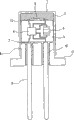
Fig. 1 is the sectional view of preferred igniter of the present invention.
Fig. 2 is the key diagram when making ignition charge be double-layer structural.
Fig. 3 is the key diagram when the upper surface of heating element heater is coated with the ignition charge constituent.
Fig. 4 is igniting Unit Installation main points are installed in expression to inflator figure.
Fig. 5 is the concept map of air bag with gas generating unit.
Fig. 6 is the concept map of gas generation device for seatbelt pretensioner.
Fig. 7 is the key diagram of central control unit.
1: cup 2: ignition charge
2 ': powder train 2 ": ignition charge constituent
3:ASIC assembly 4:ASIC
5: capacitor 6: heating element heater
7: communication electrode 8: sealing-plug
9: electrode pin 10: glass capsulation
11: flange 12: the igniting electrode
13: housing 21: the air bag gas generating unit
22: igniter 23: combustion adjuvant
24: gas-forming agent 25: filter
26: gabarit container 27: hole
31: gas generation device for seatbelt pretensioner (micro gas generator)
32: igniter 33: gas-forming agent
34: base station (support) 35: cup
110: central control unit 111a~111d: air bag module
112: the 1 power supply electric conductors power supply in 113: the 2 electric conductor
114,115: electrode pin
The specific embodiment
Below, the present invention is specifically described.
Fig. 1 represents igniter of the present invention with sectional view.Among the figure, numbering 1 is a metal system cup, the 2nd, and ignition charge.The 3rd, the ASIC assembly with resin forms the substrate plastic packaging wherein is equipped with the necessary elements of electronic circuit such as ASIC or capacitor on this substrate, and 4 is ASIC among the figure, and the 5th, capacitor.Here, so-called ASIC (Application Specific Integrated Circuit, special IC) 4 integrated circuits that are meant towards special-purpose, in the present invention, this ASIC4 plays a role as mutual communication switch mechanism, described mutual communication switch mechanism and outside communication mutually, and according to through information encoded igniter being lighted a fire.And capacitor 5 plays a role as the accumulating mechanism of electric energy.
And 6 are arranged on the heating element heater at the top of ASIC assembly 3, the 7th, be provided in the communication electrode of the bottom of ASIC assembly 3 equally.In addition, the substrate of ASIC assembly 3 also can use lead frame.
And 8 belong to the system sealing-plugs, on sealing plug 8, are fixing to be used for the electrode pin 9 that is electrically connected with the outside by glass capsulation 10.Like this, fix electrode pin, can keep high-air-tightness thus and guarantee electric insulation by glass capsulation.And then, metal system cup and sealing-plug metal part are welded, can make the inside of cup under high-air-tightness, obtain sealing thus.And 11 are arranged on the metal system flange of the peripheral part of sealing-plug 8.As the preference of flange usefulness metal, for example can enumerate cold-rolled steel sheet (Steel Plate Cold rolled, SPC) Ferrious material such as grade of stainless steel, ferronickel and process nickel plating.
Among the present invention, at first dispose pulverous ignition charge 2 in the deep of cup 1.This ignition charge 2 is a kind of single layer configuration of gunpowder as can be as shown in Figure 1, but is double-layer structural as shown in Figure 2 more advantageously, that is, dispose in the outside of ignition charge 2 lead the stronger powder train of bad temper 2 '.
Here, powder train 2 ' preferably in composition, contain zirconium.In addition, the powder train that contains titanium hydroxide, boron or trinitroresorein etc. also is fit to.
And as ignition charge 2, except described material, for example can also using, the Japan Patent spy is willing to that 2001-140468 specification or Japan Patent spy drive the ignition charge that the 2002-362992 communique is disclosed, and are not particularly limited.
Then, ignition charge 2 disposes heating element heater 6 contiguously therewith.
At this moment, for making heating element heater and contacting of ignition charge be more stable advantageously, at the upper surface of heating element heater coating ignition charge constituent 2 " as shown in Figure 3.
As such heating element heater 6, what be fit to is the so-called SCB chip of the enough low-yield igniting of energy.And, if make this SCB chip be the bridge structure that metal and insulant is stacked, then can be with the bigger spark of low-yield generation, so more favourable.
Here, so-called SCB is meant semiconductive bridge (Semiconductor Bridge), is to use the manufacturing step of common semiconducter IC and the heating element heater made.
As described bridge structure, also can be suitable for will be from respectively one or more the alternately laminated structure that forms of constituent the group of the group of titanium, nichrome, nickel, aluminium, magnesium and zirconium and calcium, manganese, silica and silicon.
As preferred bridge structure, more suitable is alternately to be laminated with titanium and SiO on silicon substrate
2The structure of (perhaps boron).The thickness of each layer is respectively about preferred 0.05 μ m~10 μ m.Preferred thickness is 0.1 μ m~4 μ m.
In addition, with being electrically connected of heating element heater 6, carry out with electrode 12 via the igniting that is arranged on ASIC assembly 3 upper surfaces.
In the ASIC assembly 3 among the present invention, built-in ASIC4 and capacitor 5, described ASIC4 be as being used for carrying out mutual communication and triggering the mechanism of specific electric pulse row, and described capacitor 5 is accumulated mechanism as electric energy.
In addition, this ASIC assembly 3 be incorporated into via two electrode pins 9 with aftermentioned central control unit contact in the gas-bag system of LANization.
And described ASIC assembly 3 must be as the cylindrical shape along the size of the internal diameter of cylindrical cup 1, and is inserted into swimmingly in this cup 1.For this reason, the external diameter of ASIC assembly 3 be preferably greater than equal glass internal diameter 85%, smaller or equal to about 99% of cup internal diameter.
Here, the diameter that is provided in the communication electrode 7 of ASIC assembly 3 bottoms preferably is slightly less than the diameter of electrode pin 9, even the contact position of communication electrode 7 and electrode pin 9 is because tolerance during assembling etc. and departing from slightly, also both can be maintained engagement state always, thereby be kept being electrically connected.
And in order to keep stable contact when brute force is pushed, the contact portion that advantageously makes communication electrode 7 and electrode pin 9 is smooth.
Among the present invention, as mentioned above, at the deep of cup 1 filling point gunpowder 2, insert ASIC assembly 3 then and be connected to ignition charge 2 so that be configured in the heating element heater 6 at these ASIC assembly 3 tops, then, insert sealing-plug 8 so that the electrode pin 9 that is arranged on the sealing plug 8 is connected to the communication electrode 7 that is provided in described ASIC assembly 3 bottoms, then with cup 1 and sealing-plug 8 welding and integrated.
Thus, the inside that comprises the igniter of ASIC is that the metallic object by tool electric conductivity is covered with, and is fixed on the gas generating unit via flange, therefore can shield electromagnetic wave noise etc. effectively.
And, integrated by welding, kept inner air-tightness.
And then igniter integral body is covered by metallic object, thus, when exposing to the open air at high temperature even gas generating unit meets with fire etc. in transportation, also explosion can not take place and safer.
About this point, previous igniter utilizes plastics to keep insulating, therefore the resin part must be softened when meeting with fire, might be blown because of the interior pressure that gas-forming agent is done the time spent to fly, disperse, thereby must work hard especially to prevent this kind situation.
And, by welding cup 1 and sealing-plug 8 when integrated, are preferably being carried out this welding under the state that sealing-plug 8 is pressed in the cup 1.
That is, if under the state that with the pressure more than to a certain degree sealing-plug 8 is pressed in the cup 1, weld, then communication electrode 7 and electrode pin 9 engages can the resin plastic-sealed ASIC assembly 3 of reason to become to push with the elastic reactance of cup 1 and engages, the result, when even igniter is subjected to the impact of sizable power, also can advantageously avoid the cut-out that is connected of communication electrode 7 and electrode pin 9.
And, if communication electrode 7 is the aforesaid joint of pushing with engaging of electrode pin 9, then ASIC assembly 3 also can act on opposition side with the elastic reactance of cup 1, therefore the heating element heater 6 that is arranged on these ASIC assembly 3 opposition sides engages under crimped status with ignition charge 2, that is, the density of ignition charge 2 improves, and therefore can realize igniting reliably and advantageously shorten the duration of ignition.
And then, compare with the structure that utilizes scolding tin or welding to fix connecting portion, aforesaid to push joint not only easy, and the advantage that needs to connect required volume is hardly arranged.
Here, described sealing-plug 8 is pressed into about the preferred 1MPa~250MPa of the power that is pressed in the cup 1.Its reason is, if be pressed into power deficiency 1MPa, then can't obtain to engage fully the pressing force of communication electrode 7 and electrode pin 9, on the other hand, if the power that is pressed into surpasses 250MPa, the stress that then puts on the ASIC assembly can become excessive, thereby has the ASIC assembly to produce damaged danger.In addition, be pressed into the more preferably scope of 2MPa~130MPa of power.
And, among the present invention, also can be as shown in Figure 3 as, at the upper surface of heating element heater 6 point of application gunpowder constituent 2 " in advance.That is, at the ignition charge of upper surface dispensing (dispense) pulpous state of heating element heater 6 and make it dry.This ignition charge constituent 2 " compare with the situation that only is filled with Powdered ignition charge, and ignition charge is comparatively stable with contacting of heating element heater, therefore help to realize igniting reliably and shorten the duration of ignition.
Igniter of the present invention is arranged on be provided with in the body, in for example inflator time, comparatively ideal is as shown in Figure 4, utilizes riveted joint and flange 11 is directly engaged with the housing 13 of inflator.In addition, as method of attachment, except described riveted joint, weld also more suitable.
Its reason is, if described formation, the inside of screened ignition device effectively then, and can make igniter self via inflator electrical ground connection.
And, igniter of the present invention, ASIC assembly 3 can be arranged on the inboard that remains airtight sealing-plug 8 and cup 1, can be by contact being electrically connected of electrode 7 and electrode pin 8 of keeping in communication, therefore, even carrying ASIC assembly 3, the appearance and size that also can make igniter 1 is near previous igniter.
And then igniter use of the present invention is built in the ASIC4 of the mutual communication switch of the conduct mechanism in the ASIC assembly 3 and accumulates the capacitor 5 of mechanism as electric energy, can get in touch with outside (for example central control unit) thus.
Therefore, for example, if in being encased in automobile and be connected in via the gas-bag system of LANization in each air bag module of central control unit and use such igniter, then central control unit can only make required air bag module igniting when collision, and need not to carry the special electric energy that is used for making such igniter ignition.
Such action effect especially can be reached in the following manner: capacitor 5 is set in each igniter, this capacitor 5 is used for accumulating the contained faint energy of voltage signal that is sent by central control unit, use and to be used as heating element heater 6 by enough SCB chips of lighting a fire than previous lower energy, and be provided as the ASIC4 of mutual communication and ignition switch mechanism, this ASIC4 can detect the process information encoded from central control unit, and can send the instruction of the state that is used to transmit igniter.
In addition, in the present invention, so-called mutual communication with central control unit is employed through information encoded, be meant the state that comprises the information that makes the instruction that each igniter lights a fire and electronic component that each igniter is contained be sent to central control unit information the two.
Then, the air bag that uses igniter of the present invention is described with gas generating unit.
Fig. 5 represents the concept map of air bag with gas generating unit.As shown in Figure 5, air bag has igniter 22, combustion adjuvant (enhancer) 23, gas-forming agent 24 and filter 25 with gas generating unit 21 in inside, and the outside is that the gabarit container 26 by the combustion pressure that can bear gas-forming agent 24 constitutes.On gabarit container 26, opening the hole 27 that the gas that is used for being produced is discharged into the air bag side.
When igniter 22 runnings, combustion adjuvant 23 utilizes the heat energy that is produced by igniter 22 and burns, thereby produces high-temperature gas.Gas-forming agent 24 utilizes this high-temperature gas and burns, thereby produces the gas that is used for making the air bag expansion.This gas is the hole 27 of being opened from the gabarit container 26 of air bag and be discharged into the outside, and make gas pass through filter 25 this moment, can catch the residue of the gas-forming agent that is burnt thus, and gas self obtains cooling simultaneously.
The igniter of the application of the invention even igniter has the communicating circuit that is made of ASIC, also can be made compactly, compares the almost constant air bag gas generating unit of size with original shape thereby can easily provide.And, if use SCB to be used as heating element heater, then can light a fire at short notice, therefore can prevent the firing delay that causes by communication.
And then, the gas generation device for seatbelt pretensioner that uses igniter of the present invention is described.
Fig. 6 represents the concept map of gas generation device for seatbelt pretensioner (micro gas generator).As shown in Figure 6, micro gas generator 31 has igniter 32 and gas-forming agent 33 in inside, and igniter 32 is fixed on the metal system base station 34 that is called as support (holder).And then the cup 35 that holds gas-forming agent 33 also is the structure that is fixed on the support by for example riveting.When igniter 32 runnings, the gas-forming agent 33 in the cup 35 is used to the heat of self-ignition device 32 and burns, thereby produces gas.
In this micro gas generator, the igniter of the application of the invention even igniter has the communicating circuit that is made of ASIC, also can become compact, therefore, can provide and compare the almost constant micro gas generator of size with previous shape.Equally,, then can light a fire at short notice, therefore can prevent the firing delay that causes by communication if use SCB to be used as heating element heater.
Then, the igniting action to igniter of the present invention describes.
Under common operation condition, that is for example when the air bag that is incorporated with igniter 1 was not rolled in the accident that must launch, the capacitor of accumulating mechanism as electric energy was in following state, that is, utilize the communication of sending to use signal and energy accumulation by central control unit.
Here, when the impact owing to accident etc. required igniter 1 running, the firing command that central control unit will specific electric pulse row form was sent to the interior ASIC assembly 3 of igniter.So, in this ASIC assembly 3, discharge electric energy from capacitor 5 by electronic switch, discharge to heating element heater 6 with the electric energy that will be accumulated.Heating element heater 6 is used to the electric energy of self-capacitance device 5 and ignition charge 2 is taken fire.
Then, the control main points to central control unit describe.
Fig. 7 represents to be integrated with the example of gas-bag system of the LANization of central control unit 110 and four air bag module 111a, 111b, 111c, 111d.Two air bag module 111b and 111c can have respectively for example make before the gas generator that expands of air bag, other two air bag module 111a and 111d can have the gas generator that the side air bag is expanded respectively.
Taking in igniter in the gas generator that these modules are contained separately, each igniter has two electrode pins 114,115, electrode pin 114 is connected in the 1st power supply electric conductor of getting in touch with central control unit 110 112, and electrode pin 115 is connected in the 2nd power supply electric conductor of getting in touch with central control unit 110 113.
Under common operating state, that is, when automobile is not rolled in the specific impact that need to activate or more than one air bag module 111a, 111b, 111c, 111d, central control unit 110 is supplied with low intensive electric current to described power supply electric conductor 112,113 termly, and this electric current is sent to the electric energy of the igniter that four air bag module 111a, 111b, 111c, 111d are contained separately and accumulates in mechanism's (capacitor) via electrode pin 114 and electrode pin 115.
Produce when impacting, when for example wishing activating air bag 111c, central control unit 110 is delivered to the 1st power supply electric conductor 112 with distinctive electric pulse biographies, and described distinctive electric pulse row are configured for the firing command of the igniter of air bag module 111c.Though being listed as via electrode pin 114 and electrode pin 115, this distinctive electric pulse is sent to each igniter, but only the mutual communication means that igniter contained of air bag module 111c responds this instruction, accumulate mechanism and activate ignition switch mechanism with the electric energy that is associated, thus starting point gunpowder as mentioned above.
When wishing to activate several air bag modules, for example air bag module 111a and air bag module 111b if impact lasting, 110 pairs the 1st of central control units power supply electric conductor 112 is supplied with following peculiar electric pulse row, and these peculiar electric pulse row are used for the igniter that air bag module 111a and air bag module 111b are contained separately.Two igniter actions separately then as mentioned above.
Claims (9)
1. igniter, it possesses metal system cup and metal system sealing-plug, this metal system sealing-plug keeps many electrode pins and these electrode pins is insulated respectively, and seal the peristome of described cup and integrated with described cup, inside at described cup has ignition charge, special IC, capacitor and heating element heater, described special IC and described electrode pin, described capacitor and described heating element heater are electrically connected respectively, and then, described heating element heater is connected to described ignition charge, described igniter is characterised in that
Peripheral part at described sealing-plug possesses metal system flange, and this metal system flange is used for described sealing-plug is fixed on the body that is provided with of igniter.
2. igniter as claimed in claim 1, it is characterized in that, this igniter has the special IC assembly, wherein said special IC assembly has lift-launch at on-chip described special IC and capacitor, with resin the resin plastic-sealed top that described substrate plastic packaging forms is had the heating element heater that is being connected with described special IC, and be equipped with the communication electrode that is used for connecting described special IC and described electrode pin in this resin plastic-sealed bottom.
3. igniter as claimed in claim 2 is characterized in that, described electrode pin engages for pushing with described communication electrode.
4. as each described igniter in the claim 1 to 3, it is characterized in that described heating element heater is crimped on described gunpowder.
5. as each described igniter in the claim 1 to 4, it is characterized in that, at the upper surface point of application gunpowder constituent of described heating element heater.
6. as each described igniter in the claim 1 to 5, it is characterized in that described heating element heater is to be made of the semiconductive bridge chip.
7. igniter as claimed in claim 6 is characterized in that, described semiconductive bridge chip comprises metal and the stacked bridge of insulant.
8. air bag gas generating unit, it is characterized in that, by riveted joint or welding, will be arranged on the described flange on each described igniter in the claim 1 to 7, be electrically connected and be fixed on the metal part that body is set of the igniter that gas generator has.
9. gas generation device for seatbelt pretensioner, it is characterized in that, by riveted joint or welding, will be arranged on the described flange on each described igniter in the claim 1 to 7, be electrically connected and be fixed on the metal part that body is set of the igniter that gas generator has.
Applications Claiming Priority (2)
| Application Number | Priority Date | Filing Date | Title |
|---|---|---|---|
| JP2006001548 | 2006-01-06 | ||
| JP001548/2006 | 2006-01-06 |
Publications (1)
| Publication Number | Publication Date |
|---|---|
| CN101365921A true CN101365921A (en) | 2009-02-11 |
Family
ID=38228336
Family Applications (1)
| Application Number | Title | Priority Date | Filing Date |
|---|---|---|---|
| CNA2007800019773A Pending CN101365921A (en) | 2006-01-06 | 2007-01-05 | Ignition device, airbag, and gas generation device for seatbelt pretensioner |
Country Status (5)
| Country | Link |
|---|---|
| US (1) | US20090266265A1 (en) |
| EP (1) | EP1970663A4 (en) |
| JP (1) | JP4996481B2 (en) |
| CN (1) | CN101365921A (en) |
| WO (1) | WO2007078000A1 (en) |
Families Citing this family (3)
| Publication number | Priority date | Publication date | Assignee | Title |
|---|---|---|---|---|
| JP4813904B2 (en) * | 2006-01-06 | 2011-11-09 | 日本化薬株式会社 | Ignition device, manufacturing method thereof, gas generator for airbag, and gas generator for seat belt pretensioner |
| CN105050867B (en) * | 2013-03-18 | 2017-06-09 | 株式会社日立系统 | Igniter, igniter assembly and its detecting system and detection method |
| SE2200103A1 (en) * | 2022-09-19 | 2024-03-20 | Saab Ab | An igniter for igniting explosives or pyrotechnic composition |
Citations (3)
| Publication number | Priority date | Publication date | Assignee | Title |
|---|---|---|---|---|
| US5912427A (en) * | 1993-02-26 | 1999-06-15 | Quantic Industries, Inc. | Semiconductor bridge explosive device |
| US6096997A (en) * | 1997-08-29 | 2000-08-01 | Trw Inc. | Method of assembling an igniter including infrared testing of heating element and welds |
| US20040103811A1 (en) * | 2002-01-25 | 2004-06-03 | Mitsuyasu Okamoto | Igniter for air bag system |
Family Cites Families (18)
| Publication number | Priority date | Publication date | Assignee | Title |
|---|---|---|---|---|
| JPS6311517Y2 (en) * | 1980-07-16 | 1988-04-04 | ||
| US5200574A (en) * | 1991-04-05 | 1993-04-06 | Morton International, Inc. | Universal squib connector |
| FR2704944B1 (en) * | 1993-05-05 | 1995-08-04 | Ncs Pyrotechnie Technologies | Electro-pyrotechnic initiator. |
| FR2720493B1 (en) * | 1994-05-31 | 1996-07-19 | Giat Ind Sa | Pyrotechnic initiator. |
| US6166452A (en) * | 1999-01-20 | 2000-12-26 | Breed Automotive Technology, Inc. | Igniter |
| US6848365B2 (en) * | 2000-12-08 | 2005-02-01 | Special Devices, Inc. | Initiator with an internal sleeve retaining a pyrotechnic charge and methods of making same |
| JP4811975B2 (en) * | 2001-06-06 | 2011-11-09 | 日本化薬株式会社 | Ignition composition and igniter using the ignition composition |
| US7168737B2 (en) * | 2002-01-25 | 2007-01-30 | Daicel Chemical Industries, Ltd. | Integrated circuit for air bag system |
| JP3803636B2 (en) * | 2002-12-26 | 2006-08-02 | 本田技研工業株式会社 | Ignition device for bus connection |
| US20040244624A1 (en) * | 2003-01-31 | 2004-12-09 | Hiroshi Harada | Parts of igniter |
| US7343859B2 (en) * | 2003-11-10 | 2008-03-18 | Honda Motor Co., Ltd. | Squib |
| JP4094529B2 (en) * | 2003-11-10 | 2008-06-04 | 本田技研工業株式会社 | Ignition device |
| JP4335725B2 (en) * | 2004-03-30 | 2009-09-30 | 日本化薬株式会社 | Gas generator |
| JP4633522B2 (en) * | 2005-04-05 | 2011-02-16 | ダイセル化学工業株式会社 | Igniter assembly |
| JP4813904B2 (en) * | 2006-01-06 | 2011-11-09 | 日本化薬株式会社 | Ignition device, manufacturing method thereof, gas generator for airbag, and gas generator for seat belt pretensioner |
| JP4705550B2 (en) * | 2006-10-26 | 2011-06-22 | 日本化薬株式会社 | Gas generator for squib and airbag and gas generator for seat belt pretensioner |
| JP4714669B2 (en) * | 2006-12-01 | 2011-06-29 | 日本化薬株式会社 | Gas generator for header assembly, squib and airbag and gas generator for seat belt pretensioner |
| JP4916868B2 (en) * | 2006-12-20 | 2012-04-18 | 株式会社ダイセル | Device assembly method using electrical ignition |
-
2007
- 2007-01-05 US US12/159,877 patent/US20090266265A1/en not_active Abandoned
- 2007-01-05 EP EP07706386A patent/EP1970663A4/en not_active Withdrawn
- 2007-01-05 JP JP2007553007A patent/JP4996481B2/en not_active Expired - Fee Related
- 2007-01-05 CN CNA2007800019773A patent/CN101365921A/en active Pending
- 2007-01-05 WO PCT/JP2007/050039 patent/WO2007078000A1/en active Application Filing
Patent Citations (3)
| Publication number | Priority date | Publication date | Assignee | Title |
|---|---|---|---|---|
| US5912427A (en) * | 1993-02-26 | 1999-06-15 | Quantic Industries, Inc. | Semiconductor bridge explosive device |
| US6096997A (en) * | 1997-08-29 | 2000-08-01 | Trw Inc. | Method of assembling an igniter including infrared testing of heating element and welds |
| US20040103811A1 (en) * | 2002-01-25 | 2004-06-03 | Mitsuyasu Okamoto | Igniter for air bag system |
Also Published As
| Publication number | Publication date |
|---|---|
| EP1970663A1 (en) | 2008-09-17 |
| WO2007078000A1 (en) | 2007-07-12 |
| JP4996481B2 (en) | 2012-08-08 |
| EP1970663A4 (en) | 2012-04-04 |
| US20090266265A1 (en) | 2009-10-29 |
| JPWO2007078000A1 (en) | 2009-06-11 |
Similar Documents
| Publication | Publication Date | Title |
|---|---|---|
| US8096242B2 (en) | Squib, gas generator for air bag and gas generator for seat belt pretensioner | |
| CN102257347B (en) | Ignition system and gas generating device for airbag loaded with same | |
| JP3463263B2 (en) | Ignition device | |
| US20050115435A1 (en) | Electro-explosive device with laminate bridge | |
| CN104567555A (en) | Igniting unit for an inflator, inflator, airbag module, vehicle safety system and method of manufacturing an igniting unit | |
| EP1043201B1 (en) | Electric ignition type gas generation apparatus | |
| US7069860B2 (en) | Igniter for air bag system | |
| KR100396964B1 (en) | Igniter | |
| EP1529696B1 (en) | Squib | |
| CN101365921A (en) | Ignition device, airbag, and gas generation device for seatbelt pretensioner | |
| CN101365920A (en) | Igniter, method of producing the igniter, airbag, and gas generation device for seatbelt pretensioner | |
| JP2008138948A (en) | Header assy, squib, gas generator for air bag and gas generator for seat belt pre-tensioner | |
| JP3118048U (en) | Squib | |
| JP6781072B2 (en) | An igniter and a gas generator with the igniter | |
| US6460465B1 (en) | Ignition device for triggering a restraining device | |
| EP1315941B1 (en) | Electro-explosive device with laminate bridge and method of fabricating said bridge | |
| JP4397731B2 (en) | Ignition device | |
| US20150307058A1 (en) | Surface mount initiators | |
| KR102581020B1 (en) | Igniter for thermocell and thermocell system including same | |
| WO2000073729A1 (en) | Igniter, header assembly, and igniter plug | |
| JPH04108461U (en) | Igniter of gas generator for airbag deployment |
Legal Events
| Date | Code | Title | Description |
|---|---|---|---|
| C06 | Publication | ||
| PB01 | Publication | ||
| C10 | Entry into substantive examination | ||
| SE01 | Entry into force of request for substantive examination | ||
| C02 | Deemed withdrawal of patent application after publication (patent law 2001) | ||
| WD01 | Invention patent application deemed withdrawn after publication |
Application publication date: 20090211 |