CN101362395B - Data generation apparatus, printing apparatus and data generation method - Google Patents
Data generation apparatus, printing apparatus and data generation method Download PDFInfo
- Publication number
- CN101362395B CN101362395B CN2008101349387A CN200810134938A CN101362395B CN 101362395 B CN101362395 B CN 101362395B CN 2008101349387 A CN2008101349387 A CN 2008101349387A CN 200810134938 A CN200810134938 A CN 200810134938A CN 101362395 B CN101362395 B CN 101362395B
- Authority
- CN
- China
- Prior art keywords
- pattern
- printing
- conveying capacity
- printhead
- binary data
- Prior art date
- Legal status (The legal status is an assumption and is not a legal conclusion. Google has not performed a legal analysis and makes no representation as to the accuracy of the status listed.)
- Active
Links
Images


Classifications
-
- G—PHYSICS
- G06—COMPUTING; CALCULATING OR COUNTING
- G06K—GRAPHICAL DATA READING; PRESENTATION OF DATA; RECORD CARRIERS; HANDLING RECORD CARRIERS
- G06K15/00—Arrangements for producing a permanent visual presentation of the output data, e.g. computer output printers
- G06K15/02—Arrangements for producing a permanent visual presentation of the output data, e.g. computer output printers using printers
- G06K15/10—Arrangements for producing a permanent visual presentation of the output data, e.g. computer output printers using printers by matrix printers
- G06K15/102—Arrangements for producing a permanent visual presentation of the output data, e.g. computer output printers using printers by matrix printers using ink jet print heads
- G06K15/105—Multipass or interlaced printing
-
- B—PERFORMING OPERATIONS; TRANSPORTING
- B41—PRINTING; LINING MACHINES; TYPEWRITERS; STAMPS
- B41J—TYPEWRITERS; SELECTIVE PRINTING MECHANISMS, i.e. MECHANISMS PRINTING OTHERWISE THAN FROM A FORME; CORRECTION OF TYPOGRAPHICAL ERRORS
- B41J19/00—Character- or line-spacing mechanisms
- B41J19/14—Character- or line-spacing mechanisms with means for effecting line or character spacing in either direction
- B41J19/142—Character- or line-spacing mechanisms with means for effecting line or character spacing in either direction with a reciprocating print head printing in both directions across the paper width
- B41J19/147—Colour shift prevention
-
- G—PHYSICS
- G06—COMPUTING; CALCULATING OR COUNTING
- G06K—GRAPHICAL DATA READING; PRESENTATION OF DATA; RECORD CARRIERS; HANDLING RECORD CARRIERS
- G06K15/00—Arrangements for producing a permanent visual presentation of the output data, e.g. computer output printers
- G06K15/02—Arrangements for producing a permanent visual presentation of the output data, e.g. computer output printers using printers
- G06K15/10—Arrangements for producing a permanent visual presentation of the output data, e.g. computer output printers using printers by matrix printers
- G06K15/102—Arrangements for producing a permanent visual presentation of the output data, e.g. computer output printers using printers by matrix printers using ink jet print heads
- G06K15/105—Multipass or interlaced printing
- G06K15/107—Mask selection
Abstract
The invention relates to a data generation apparatus, printing apparatus and data generation method. When a feeding amount for multi-pass printing is changed, the purpose related to an image quality using a binary data generation pattern can still be attained by, for example, a density pattern method. Specifically, a multi-pass printing mode is identified, and a density pattern selection matrix associated with a cycle of binary data generation is selected in accordance with the selected printing mode. That is, a density pattern selection matrix employed for binary data generation using a density pattern is changed to a size corresponding to the feeding amount designated by the selected printing mode. Thereby, a phenomenon that a unit used for image processing to gain a predetermined purpose related to an image quality does not match a unit area used for a printing operation is avoided, and an image printing purpose using a binary data generation pattern can be appropriately attained.
Description
Technical field
The present invention relates to data generating apparatus, PRN device and data creation method.Particularly, the present invention relates to repeatedly scanning (moving) and the processing that transports the generation print data of execution print media between each scanning (moving) through carrying out printhead, said print data is used to accomplish the printing of the unit area of print media.
Background technology
Along with the popularization of the messaging device of for example personal computer, the PRN device that forms the terminal as image has also obtained popularization.Especially through China ink being discharged on the medium via jet and on the print media of for example paper, carrying out the ink jet printing device of printing, have for printing type non-impact type (non-impact), low noise, can carry out printing speed and be easy to the inherent advantage compatible with high density with colour print.Because these advantages, ink jet printing device become the personal PRN device that enjoys favor very soon.
So-called serial ink jet printing device uses the multiple print method usually." road (pass) " that should be noted that following use has identical definition with " scanning (scan) ".According to the multiple print method, the view data of presumptive area (unit area) is divided into the data on every kind of color and every road, and divides use mask (mask) usually for this data.
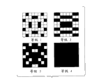
Fig. 1 is the figure that is used to explain the multiple print that adopts mask, and its situation about printing with the image of accomplishing in the unit area to four scanning of execution schematically shows printhead and the dot pattern of being printed.In Fig. 1, Reference numeral P0001 representes printhead.In order to simplify accompanying drawing and explanation, printhead P0001 is shown as and comprises the nozzle array of being made up of 16 jets (also being called nozzle hereinafter).Nozzle array is divided into first to fourth nozzle sets, and each nozzle sets comprises four nozzles.Reference numeral P0002 representes the mask pattern.In mask pattern P 0002, represent the mask pixel (print and allow pixel) that allows accordingly to print with each nozzle with ater.Complementary each other with four corresponding mask patterns of nozzle sets, and through overlapping these four patterns, 4 * 4 all pixels become prints the permission pixel.That is to say, utilize these four patterns to accomplish the printing in 4 * 4 zones.
Reference numeral P0003 to P0006 representes the arrangement pattern of formed point, and it illustrates how to scan through duplicate printing accomplishes image.Shown in these patterns, multiple print each print scanned in based on forming a little corresponding to the binary dump data (point data) that nozzle sets generated by the mask pattern.Subsequently, accomplish when print scanned at every turn, in Fig. 1, on the arrow indicated direction print media is carried the distance that equals the nozzle sets width.Through scanning by this way four times, in print media with in the corresponding zone of the width of each nozzle sets, form image.
According to above-mentioned multiple print method; Can make owing to a plurality of nozzle China and Mexico discharge directions and black discharge rate difference and print scanned between the uneven black concentration that produces of the error of the paper conveying operations carried out so not remarkable; Wherein, the difference of a plurality of nozzle China and Mexico's discharge directions and black discharge rate comes from the manufacturing process of printhead.
Example among Fig. 1 is printed to four the tunnel.Print, utilize for utilizing twice scanning to accomplish two-way that image prints that three scanning accomplishes that image prints three the tunnel prints or for for provide five the road or the multiple print of multichannel more in order to five times of accomplishing that image prints or more times scanning, carry out identical processing.That is to say, confirm basically to pass through to divide the quantity of the injection port group that the jet on the printhead provides and the amount that print media is transferred with reference to Fig. 1 explanation according to the quantity on the road that is used to accomplish printing.
Through adopting the pseudo-gray scale method (pseudo gradation method) of concentration pattern method for example or dither method, generate the binary data (point data) that is used for multiple print.When adopting the concentration pattern method, the concentration pattern of the several types with fixing point layout is provided corresponding to each concentration scale.Then, select and the corresponding concentration pattern of importing of concentration scale, and generate binary data with this according to the concentration pattern selection matrix.When adopting dither method, then use with predetermined pattern and arrange that the dither pattern of threshold value generates binary data.
Concentration pattern selection matrix and dither pattern are not prepared as big or small identical pattern or the matrix big or small and binary data that launches; But, reuse concentration pattern selection matrix and dither pattern with predetermined size according to the size of population of binary data to be launched.
Traditionally, reusable concentration pattern selection matrix and dither pattern all are fixed-size single patterns.According to TOHKEMY 2001-54956, adopt single pattern to carry out multiple print as concentration pattern selection matrix (index pattern) with fixed size.Of this conventional example, when for example switching will change the quantity on the road that is used for multiple print according to printing model, this legacy system of carrying out multiple print adopted the binaryzation pattern with fixed size.
Yet, when traditional binaryzation pattern (concentration pattern selection matrix and the dither pattern) overall situation with fixed size was used for the variable multiple print system of the quantity on road, following problem appearred.More specifically; Because the pattern of fixed size with respect to the distance measurements of between each scanning, print media being carried (hereinafter; This amount also is called the amount of feeding) possibly be unsuitable, possibly can't realize that therefore the image of the for example print quality of this design is printed target.
Specifically describe this problem below.With repetition period, generate the binary data that generates based on concentration pattern selection matrix or dither pattern according to the size of concentration pattern selection matrix or dither pattern.
In this case, when the amount of feeding is binary data when generating the integral multiple of repetition period of (binaryzation pattern), the identical binary data repetition period is applied to all unit areas.So, can not arrange difference and be applied to the some formation order difference of unit area and deterioration in image quality occurs because of the point that is applied to unit area.Yet when the amount of feeding was not the integral multiple of repetition period of binary data (binaryzation pattern), the binary data repetition period in these unit areas occurred in a different manner.In addition, the same repetition period that binary data generates is corresponding to the unit area of two vicinities, and therefore definite binaryzation pattern, the especially size of binaryzation pattern act on different unit areas through considering the picture quality target.As a result, possibly make that the point in the unit area arranges that be different with some formation order in these unit areas, and possibly occur because the deterioration in image quality that point is arranged and the difference of some formation order causes.
Summary of the invention
The purpose of this invention is to provide a kind of data generating apparatus, PRN device and data creation method; Wherein, When the amount of feeding of multiple print changed, for the constituent parts zone, the repetition period that binary data generates (binaryzation pattern) can occur in an identical manner.
In first aspect of the present invention; A kind of data generating apparatus is provided, has been used to generate the binary data that is used on print media, carrying out printing, in said printhead, be furnished with a plurality of nozzles through the use printhead; Said data generating apparatus comprises: portion is set; Be used to be provided with printing model, in said printing model, carry out repeatedly moving of said printhead; And between said each moving of repeatedly moving, said print media is carried the conveying capacity less than the layout width of said a plurality of nozzles of said printhead, with the corresponding zone of said conveying capacity on carry out and print; Selection portion; Be used for the mutually different a plurality of binaryzation patterns of pixel count from the throughput direction of said print media, select to have and binaryzation pattern corresponding to the corresponding pixel count of approximate number of the pixel count of the said conveying capacity in the said printing model that by the said portion of setting; And generation portion, be used for the binaryzation pattern selected by said selection portion through using, generate and the corresponding binary data in said zone.
According to a second aspect of the invention, a kind of data generating apparatus is provided, has been used to generate the binary data that is used on print media, carrying out printing through the use printhead; In said printhead, be furnished with a plurality of nozzles, said data generating apparatus comprises: portion is set, is used for being provided with a printing model of a plurality of printing models that comprise first printing model and second printing model; In said first printing model; Carry out M time of said printhead and move, and between each the moving of moving for said M time, said print media is carried first conveying capacity less than the layout width of said a plurality of nozzles of said printhead, on the zone that has with the corresponding width of said first conveying capacity, to carry out printing; Wherein, Said M is equal to or greater than 2 integer, in said second printing model, carries out N time of said printhead and moves; And between said N mobile each moving, said print media is carried second conveying capacity less than said first conveying capacity; Print on the zone that has with the corresponding width of said second conveying capacity, to carry out, wherein, said N is the integer greater than said M; And generation portion; Be used for when being provided with said first printing model; Through using the first binaryzation pattern to generate and the said regional corresponding binary data that has with the corresponding width of said first conveying capacity; And when being provided with said second printing model; Through using the second binaryzation pattern to generate and the said regional corresponding binary data that has with the corresponding width of said second conveying capacity, wherein, the said first binaryzation pattern has on the throughput direction of said print media and the corresponding pixel count of approximate number corresponding to the pixel count of said first conveying capacity; The said second binaryzation pattern is different from the said first binaryzation pattern, and on said throughput direction, has and the corresponding pixel count of approximate number corresponding to the pixel count of said second conveying capacity.
In the third aspect of the invention, a kind of PRN device is provided, be used for through using printhead on print media, to carry out printing; In said printhead, be furnished with a plurality of nozzles, said PRN device comprises: portion is set, is used for being provided with a printing model of a plurality of printing models that comprise first printing model and second printing model; In said first printing model; Carry out M time of said printhead and move, and between each the moving of moving for said M time, said print media is carried first conveying capacity less than the layout width of said a plurality of nozzles of said printhead, on the zone that has with the corresponding width of said first conveying capacity, to carry out printing; Wherein, Said M is equal to or greater than 2 integer, in said second printing model, carries out N time of said printhead and moves; And between said N mobile each moving, said print media is carried second conveying capacity less than said first conveying capacity; Print on the zone that has with the corresponding width of said second conveying capacity, to carry out, wherein, said N is the integer greater than said M; And generation portion; Be used for when being provided with said first printing model; Through using the first binaryzation pattern to generate and the said regional corresponding binary data that has with the corresponding width of said first conveying capacity; And when being provided with said second printing model; Through using the second binaryzation pattern to generate and the said regional corresponding binary data that has with the corresponding width of said second conveying capacity, wherein, the said first binaryzation pattern has on the throughput direction of said print media and the corresponding pixel count of approximate number corresponding to the pixel count of said first conveying capacity; The said second binaryzation pattern is different from the said first binaryzation pattern, and on said throughput direction, has and the corresponding pixel count of approximate number corresponding to the pixel count of said second conveying capacity.
In fourth aspect of the present invention; A kind of data creation method is provided, has been used to generate the binary data that is used on print media, carrying out printing, in said printhead, be furnished with a plurality of nozzles through the use printhead; Said data creation method comprises: step is set; Be used to be provided with printing model, in said printing model, carry out repeatedly moving of said printhead; And between said each moving of repeatedly moving, said print media is carried the conveying capacity less than the layout width of said a plurality of nozzles of said printhead, with the corresponding zone of said conveying capacity on carry out and print; Select step; Be used for the mutually different a plurality of binaryzation patterns of pixel count from the throughput direction of said print media, select to have with corresponding to binaryzation pattern by the corresponding pixel count of approximate number of the said pixel count that said conveying capacity in the said printing model that step is provided with is set; And the generation step, be used for generating and the corresponding binary data in said zone through using binaryzation pattern by said selection step selection.
According to said structure, even the amount of feeding of multiple print changes, the repetition period that binary data generates (binaryzation pattern) can be applied to each unit area in an identical manner.Therefore, the point of unit area is arranged and some formation can be applied to the constituent parts zone in full accordly, and can be owing to deterioration in image quality appear in a difference of arranging and putting in the formation order.
With reference to the description of accompanying drawing to exemplary embodiments, more characteristics of the present invention will become clear through following.
Description of drawings
Fig. 1 is that the multiple print method of printhead and the sketch map of the dot pattern of being printed are used in explanation;
Fig. 2 is the figure that the relation between the printhead and print media when carrying out two-way and print is shown;
Fig. 3 A and Fig. 3 B are used to explain according to the first embodiment of the present invention to use C, M and Y China ink to carry out the figure of the situation of two-way printing;
Fig. 4 is main explanation as the block diagram according to the hardware and software structure of the personal computer of the image processing equipment of first embodiment;
Fig. 5 illustrates the flow chart of handling for the performed image of first embodiment;
Fig. 6 is the figure that the concentration pattern that is used for first embodiment is shown;
Fig. 7 is used to explain the figure that repeats the relation between the generation cycle and the amount of feeding about the binary data of first embodiment;
Fig. 8 is the sketch map that the relation between printhead and the print media is shown to three tunnel printings;
Fig. 9 is or not that the situation of the approximate number of the amount of feeding is explained the amount of feeding and repeated the figure of the relation between the generation cycle in the generation cycle that repeats to binary data;
Figure 10 is to printing the figure that the amount of feeding and the relation between the repetition period are shown according to three tunnel of first embodiment;
Figure 11 is the flow chart that is used for changing explicitly with the change of the used way amount of multiple print the processing that repeats the cycle that generates of binary data that illustrates about first embodiment;
Figure 12 A to Figure 12 D is the figure that is used to explain the interference that the mask pattern that is used to quantize print data is produced;
Figure 13 A to Figure 13 D is the sketch map of handling below the explanation, and this processing is used for the calculating of repulsive force gesture and the decay of total utilisable energy;
Figure 14 is the sketch map that the function of basic repulsive potential E (r) according to a second embodiment of the present invention is shown;
Figure 15 is the flow chart that is used to use the method for being disposed in order to arrange print to allow the processing of pixel that illustrates according to second embodiment;
Figure 16 is the concept map to the performed calculating of mask C that illustrates about second embodiment;
Figure 17 is the figure that illustrates based on the some arrangement pattern of index data;
Figure 18 is the figure that illustrates based on pattern point arrangement pattern shown in Figure 17, that should consider when making mask;
Figure 19 is the figure based on other arrangement pattern of index data that illustrates according to second embodiment;
Figure 20 is the figure that illustrates based on pattern point arrangement pattern shown in Figure 19, that should consider when mask is made; And
Figure 21 is the figure that exemplary concentration pattern selection matrix is shown.
The specific embodiment
Describe the preferred embodiments of the present invention below with reference to accompanying drawings in detail.
Printer selectivity as according to the ink jet printing device of first embodiment of the invention is carried out a plurality of printing models, for these a plurality of printing models, in multiple print, uses the road and different conveying capacities of varying number.Will be said like hereinafter with reference to Figure 11, according to the amount of feeding of the corresponding print media of selected printing model, change the repetition period (repetition period of binaryzation pattern) that binary data generates.
Fig. 2 illustrates the sketch map of treating by the relation between printhead and the print media in the two-way printing model of the printing model of carrying out according to the printer of this embodiment.In the two-way printing model, printhead scanning and printing medium twice is printed with the image of accomplishing in the unit area on the print media.
To be used for cyan, magenta and each yellow color nozzle array and be divided into first group and second group that includes 256 nozzles.Therefore, a kind of nozzle quantity of color is 512.When printhead with substantially perpendicular to the direction of nozzle array direction (" scanning direction " represented by the double-head arrow among Fig. 2) scanning and printing medium the time, China ink is discharged to the print media respectively and the corresponding constituent parts of the array-width of each nozzle sets zone from the color nozzle array.In this example,, C, M and Y China ink are discharged to the constituent parts zone based on C, M and Y binary pattern data.In addition; When the end of scan; With print media perpendicular to (across) direction of a scanning direction (at this, " the print media throughput direction " represented by the arrow among Fig. 2) goes up the amount (in this case, 256 length in pixels equal the width of unit area) of carrying the width that equals a group.Like this, through twice scanning image is printed in each unit area.Hereinafter, also be called as the amount of feeding in order to accomplish image to print in the conveying capacity of repeatedly between the scanning print media being carried.As shown in Figure 2, the amount of feeding (conveying capacity) is expressed as the value that equals Nf (=256) length in pixels.
Now the two-way printing model will be described more specifically.In scanning for the first time,, print the regional A of print media through use separately first group of C nozzle array, M nozzle array and Y nozzle array with named order.Then, in scanning for the second time,, on the regional A that scanning has been printed for the first time, print remaining data through use separately second group of Y, M and C nozzle array with named order.In addition, through separately first group of the Y that uses in order with this, M and C nozzle array, print not print area B.Repeat this processing, thereby carry out the printing in constituent parts zone (regional A and area B) with the order of C1, M1, Y1, Y2, M2 and C2 or with the order of Y1, M1, C1, C2, M2 and Y2.
Fig. 3 A and Fig. 3 B are the figure that is used for explaining to the situation that will use C, M and Y China ink to carry out the two-way printing as shown in Figure 2 the order of printing unit area.
In Fig. 3 A, show process with order print image in zone (the regional A of Fig. 2) of forward scan and reverse scan.In forward scan (first via) as the scanning first time, at first, will be said like hereinafter with reference to Fig. 5, be that the cyan point data that every road generates is printed cyan image based on utilizing mask.Then, based on the point data of utilizing mask to generate in the same manner equally, through same scanning and printing magenta and yellow image.That is to say that magenta color image is overlapping with the previous cyan image of printing, and through coming the print yellow image with cyan and magenta color image are overlapping.With the print media transfer predetermined amounts, then, carry out identical processing in reverse scan (the second tunnel) as scanning for the second time.That is to say, be yellow, magenta and the cyan point data that every road generates based on utilizing mask, through coming print image with previous images printed is overlapping.
In Fig. 3 B, the image that shows in accomplishing zone (area B among Fig. 2) is printed process before, for this process, prints with the order execution of reverse scan and forward scan.As the reverse scan (first via) of scanning for the first time, based on yellow dots will data print yellow image, it is that every road generates that these yellow dots will data are based on mask.After this, in same one scan, based on the point data of utilizing mask to generate for the road in the same manner, printed product redness and cyan image.That is to say, through coming the printed product red image, and print cyan image on yellow of formerly printing and the magenta color image with the yellow image of previous printing is overlapping.Subsequently, after with the print media transfer predetermined amounts,, similarly, utilize the cyan, magenta and the yellow dots will data that generate in the above described manner, formerly print image successively on the images printed as the forward scan (the second tunnel) of scanning for the second time.
Fig. 4 is the block diagram that the hardware and software structure of personal computer (hereinafter, also abbreviating PC as) mainly is described, this personal computer is the image processing equipment (data generating apparatus) according to present embodiment.In the present embodiment, computer 100 is defined as image processing equipment (data generating apparatus), and it is equipped with printer driver 103, to carry out hereinafter the binary data shown in the Figure 11 that describes is generated processing.Yet image processing equipment of the present invention (data generating apparatus) is not limited to this structure.For example, when printer 104 execution were handled as the binary data generation of characteristic of the present invention, printer 104 was as image processing equipment (data generating apparatus).
In Fig. 4, utilize operating system (OS) 102 to operate each software product as the PC 100 of master computer, for example application software 101, printer driver 103 and monitor driver 105.The processing that application software 101 execution are relevant with word processing, spreadsheet program and explorer.Monitor driver 104 carry out for example create will be on monitor 106 processing of images displayed data.
The view data of OS 102 etc. is exported in printer driver 103 processing from application software 101, and generates binary system discharge (point) data that finally are used for printer 104.Particularly, printer driver 103 is carried out the processing that hereinafters will be described with reference to Fig. 5 and Figure 11, thereby based on C, M and Y multi-level images data, generation is used for C, M and the Y binary picture data of printer 104.Give printer 104 with the binary picture data transmission (providing) that so obtains.
As said with reference to Fig. 2, the printer 104 in the present embodiment is so-called serial printers, and this serial printer, and is discharged China ink in scan period from printhead and printed to carry out scanning with respect to print media mobile print head.The printhead that comprises the injection port group of C, M and Y China ink color is installed on balladeur train, and scans the for example print media of paper.Respectively with printhead in the black stream that is communicated with of each jet in, the type element of electrothermal conversioning element for example or piezoelectric element is set, and, through driving these type elements, discharge China ink from jet.The layout density of jet is 1200dpi, and discharges the China ink of 3.0 skin liters (picoliter) from each jet.In addition, for each color nozzle array 512 jets are set.
In an embodiment of the present invention, adopt the concentration pattern method, generate binary data through six planes of the forward direction in the multiple print pattern and reverse scan and C, M and Y China ink color differentiating.Fig. 5 illustrates this binary data to generate the flow chart of handling.
In Fig. 5, at first, RGB 8 Bit datas are carried out the color adjustment handle (S401), and handle the CMY view data that (S402) obtains 8 bits through carrying out colour switching.Then, view data being carried out Gamma correction handles.
After this, 256 grades of CMY 8 bit image data that obtain through above-mentioned processing are quantized, and obtain 5 values (level) data (S404) of 3 bits through error diffusion.Then, based on 5 grade data, utilize concentration pattern shown in Figure 6 (some arrangement pattern) to carry out binary data and launch (S405).Should be noted that 5 grade data that obtain at step S404 have the resolution ratio of a pixel 600dpi, and concentration pattern (some arrangement pattern) adopts 2 pixels * 2 pixels as a unit.The resolution ratio of the binary data that therefore, is generated is 1200dpi * 1200dpi.
Fig. 6 is the figure that illustrates according to the concentration pattern of present embodiment.As shown in Figure 6, be that each concentration scale of 5 grade data provides four concentration pattern types.In binary data launches to handle, depend on the concentration scale of 5 grade data appointments, according to concentration pattern selection matrix appointed pattern type selecting concentration pattern, and with the binary data of this concentration pattern as 2 pixels * 2 pixel units.For example, when the concentration scale of 5 grade data appointments is the value of " 1 " and concentration pattern selection matrix during for " 0 ", from four types of concentration pattern grade 1 (2 pixels * 2 pixels, a point is for opening (ON)), select the 0th concentration pattern.Through repeating this processing, with the resolution ratio generation binary picture of 1200dpi * 1200d pi.
In the present embodiment, the pattern that adopts the concentration pattern selection matrix shown in Figure 21 is as the binaryzation pattern.The concentration pattern selection matrix of present embodiment has the size of 32 pixels * 32 pixels, and in each pixel, imports four values of from 0 to 3 brokenly.For each pixel in the concentration pattern selection matrix, arrive the pixel value of " 3 " based on " 0 ", the concentration pattern of 2 pixels * 2 pixels is launched.That is to say,, binary data (point) pattern of 1200dpi * 1200dpi is changed into 64 pixels (main scanning direction) * 64 pattern in pixel (direction of feed) cycle according to 32 pixels * 32 pixel sizes of concentration pattern selection matrix.The size of supposing the concentration pattern selection matrix is 100 pixels * 100 pixels, then binary data pattern is expanded into the pattern of 200 pixels * 200 pixel period.In the size or cyclomorphosis processing with the embodiment of the invention of describing, concentrate on the size of the pattern that utilizes the expansion of concentration pattern selection matrix hereinafter.Yet identical processing also can be applicable to the size or the cycle of concentration pattern selection matrix itself.
With reference to Fig. 5, last once more, the binary data based on launching through binary data to obtain uses mask to obtain to be respectively applied for the binary data (S406) on six planes.
In addition; Obvious from following description; The present invention also can be applicable to following situation, in this situation, except C, M and Y, has also used the China ink of four kinds of colors that comprise black (Bk); Perhaps in this situation, adopted perhaps for example red, the blue and green special color China ink of China ink that comprises light color China ink with low concentration.
First embodiment
According to first embodiment of the invention, a printing model of selecting from a plurality of printing models is set, and confirms and the corresponding amount of feeding of selected printing model that the way amount of multiple print is different between these a plurality of printing models.Then, in order to use size and the corresponding concentration pattern selection matrix of the determined amount of feeding, from a plurality of concentration pattern selection matrixs, select a matrix with above-mentioned size.
As said with reference to Fig. 2, in the two-way printing model of present embodiment, owing to the nozzle quantity (512) that is provided with for printhead, amount of feeding Nf equals 256 length in pixels.According to this amount of feeding; In the two-way printing model; The size of concentration pattern selection matrix on direction of feed is defined as 32 length in pixels, and will waits that the repetition period Ng of binary data on direction of feed that utilizes the concentration pattern matrix to launch is defined as 64 length in pixels.That is to say that amount of feeding Nf is the integral multiple of repetition period Ng, that is, repetition period Ng (=64 pixel) is defined as the approximate number of amount of feeding Nf (=256).
Fig. 7 is the figure that is used to explain the relation between the repetition period and the amount of feeding.As shown in Figure 7, the upper end of regional A and B etc. all the time with the repetition period in same position (pixel) consistent, each zone among regional A and the B etc. is through scanning repeatedly and accomplishes the unit area of printing.
Next, with describing the way amount of multiple print is changed into three tunnel situation through changing printing model etc.
Fig. 8 is used to explain that three the tunnel print, and schematically shows the figure of the relation between printhead and the print media.To describe like hereinafter, in three tunnel printing models, printhead scanning and printing medium three times is printed with the image in the predetermined unit zone of accomplishing print media.
Cyan, magenta and yellow nozzle array are divided into first, second and the 3rd group that includes 168 nozzles respectively.In the present embodiment, selective value 168 be because its near through with 512 nozzles (in this case, corresponding to pixel) obtain divided by 3 170.
Printhead is being gone up the scanning and printing medium perpendicular to the direction of arrangement of nozzles direction (" scanning direction " represented by the double-head arrow among Fig. 8), and China ink is discharged to all the corresponding unit area of nozzle array width with each nozzle sets from nozzle array.In this example,, C, M and Y China ink are discharged to the constituent parts zone based on C, M and Y binary picture data.In addition, when the end of scan, with print media perpendicular to (across) direction of printhead scanning direction (" the print media throughput direction " represented by the arrow among Fig. 8) goes up the amount of carrying the width that equals a nozzle sets, the i.e. amount of feeding=168 length in pixels.Then, repeat identical operations once more, and accomplish the printing in constituent parts zone through three scanning.
At this moment, suppose that the repetition period Ng (=64) that binary data generates is not the approximate number of amount of feeding Nf (=168 pixel), i.e. supposition does not change the repetition period.Fig. 9 is amount of feeding Nf and the figure of the relation between the repetition period Ng that is used to explain in this case.
Suppose that the original position with regional A is defined as 0, and consistent with the original position of repetition period.At this moment, the original position of area B representes to equal coordinate 168 amount of feeding (168 pixel), on the direction of feed.When repetition period Ng equals 64 length in pixels, be different from two-way and print situation, the origin coordinates 168 of area B can not be eliminated by 64.That is to say that the binary data that the diverse location in the repetition period (pixel) is located is relevant with regional A and area B respectively as a whole.In addition, after print media is carried 168 length in pixels, obtain origin coordinates 340 to zone C.This expression binary data generates period migration, and in addition, the binary data that the diverse location in the repetition period (pixel) is located is whole relevant with two zones.When amount of feeding Nf was not the integral multiple of repetition period Ng by this way, the repetition period that binary data generates (binaryzation pattern) occurred between a plurality of unit areas in a different manner.Then, the point of unit area is arranged and is put formation and becomes different each other between a plurality of unit areas in proper order.As a result, possibly occur because the image deterioration that point is arranged and the difference of some formation order causes.
According to present embodiment, when changing the way amount of multiple print, adopt the amount of feeding that changes in response to the change of way amount, to change the repetition period Ng that binary data generates.In the present embodiment, for three tunnel printings, repetition period Ng should be as 84 of the approximate number of amount of feeding Nf (=168 pixel).Particularly, three tunnel shown in the example printed hereto, adopts to be different from 42 pixel (the main scanning directions two-way print matrix, that be used for three tunnel printings; Scanning direction) * 42 pixel (directions of feed; The print media throughput direction) matrix is as the concentration pattern selection matrix.In addition, concentration pattern is defined as has 2 pixels * size of 2 pixels.Therefore, when carrying out concentration pattern expansion processing, on scanning direction and direction of feed, all generate the binary data of 84 pixels.
Preferably, will describe, and select value greater than minimum of a value 32 as approximate number like hereinafter.That is to say that effectively, the concentration pattern method should be designed to prepare a plurality of concentration pattern according to concentration scale, thereby make and to be used to select the cycle of these concentration pattern will become irregular.Through the pattern scrambling, can prevent overlapping the changing of point when the dot printing offset.In order to carry out the irregular selection of concentration pattern, the cycle of concentration pattern selection matrix or size should increase to a certain degree.According to the application inventor's research, the concentration pattern selection matrix of at least 32 pixels is preferred.In the present embodiment, prepare in advance and the corresponding concentration pattern selection matrix of the amount of feeding.Yet, the invention is not restricted to this aspect.For example, can only prepare a concentration pattern selection matrix (for example, 100 pixels * 100 pixels), and can this concentration pattern selection matrix be cut into and the corresponding pattern magnitude of the amount of feeding greater than the size that each amount of feeding adopted.As the advantage of this scheme, need not to prepare in advance the concentration pattern selection matrix of a plurality of different sizes.
Figure 10 is the figure that prints the relation between amount of feeding Nf and the repetition period Ng that illustrates to three tunnel of present embodiment.Shown in figure 10, when the amount of feeding became the value that equals 168 length in pixels, the repetition period also became the repetition period that equals 84 length in pixels.
According to said structure, can suitably reach the improved image printing purpose of for example picture quality that will utilize concentration pattern to realize.More specifically, prepare the concentration pattern selection matrix that point is arranged and pattern magnitude is confirmed by matrix size, thereby make it possible to reach predetermined purpose about picture quality.Accomplishing the unit area of printing through multiple print is to have specified the for example unit of the various conditions of the printing of the use order of print-head nozzle.Be used in image and handle reaching consistent with the unit that is used for printing, and therefore can suitably reach the image printing purpose of use binary data generation pattern about the unit of the predetermined purpose of picture quality.
Figure 11 is that the binary data that illustrates according to present embodiment generates processing, the flow chart of the processing that the repetition period that especially binary data is generated is relevant with conveying capacity with the way amount of multiple print.
At first, in main process equipment, have from appointment and to select a printing model (S1201) a plurality of printing models of different conveying capacities and different way amounts.Printing model can be selected by the user, perhaps can be selected automatically based on view data by main frame.Printing model so selected in main frame is set to the operator scheme that is used to print.Available printing model can be three or more a plurality of, but in order to simplify description, supposes that in the following description two printing models can use.
Then, carry out inspection, to judge that the printing model that is provided with in the main frame is first printing model or second printing model (S1202).First printing model is the pattern that execution is printed with reference to the two-way that Fig. 2 and Fig. 7 explained.Particularly, first printing model is such pattern, in this pattern, through carrying out M (M is equal to or greater than 2 integer, M=2 in this case) inferior scanning and between said M scanning, print media being carried the first conveying capacity (amount of feeding; The Nf=256 pixel), accomplish the printing of width and the corresponding unit area of first conveying capacity on throughput direction.On the other hand, second printing model is the pattern of execution with reference to three tunnel printings that Fig. 8 and Figure 10 explained.Particularly; Second printing model is such pattern; In this pattern, through carrying out the inferior scanning of N (N is different from M and is equal to or greater than 2 integer, N=3 in this case) and between said N scanning, print media being carried the second conveying capacity (amount of feeding; The Nf=168 pixel), accomplish the printing of width and the corresponding unit area of second conveying capacity on throughput direction.
When being judged as at step S1202 when being provided with first printing model, processing controls gets into step S1203, and selects the first concentration pattern selection matrix (the first binaryzation pattern) as concentration matrix pattern to be used.As described with reference to Fig. 7 and Figure 21, the size of the first concentration pattern selection matrix (the first binaryzation pattern) is 32 pixels * 32 pixels (for binary data, 64 pixels * 64 pixels), and it is the approximate number of first conveying capacity (Nf=256 pixel).Therefore, can make the size of repetition period Ng that binary data generates and binaryzation pattern be respectively the approximate number of first conveying capacity (Nf=256 pixel).Then, utilize the first concentration pattern selection matrix to carry out binary conversion treatment, to generate binary data (S1204).The binary data of step S1204 generate handle with Fig. 5 in the binary conversion treatment of step S405 corresponding.After this, the mask that utilizes two-way to print will be divided into twice scanning at the binary data that step S1204 generates, thereby make the binary data (S1205) that obtains the two-way printing according to twice scanning.The binary data of step S1205 divide handle with Fig. 5 in to divide processing corresponding the road of step S406.
On the other hand, when being judged as at step S1202 when being provided with second printing model, processing controls jumps to step S1206, and selects the second concentration pattern matrix (the second binaryzation pattern) as concentration pattern matrix to be used.As said with reference to Figure 10, the size of the second concentration pattern selection matrix (the second binaryzation pattern) is 42 pixels * 42 pixels (for binary data, 84 pixels * 84 pixels), and it is the approximate number of second conveying capacity (Nf=168).Therefore, can make the size of repetition period Ng that binary data generates and binaryzation pattern be respectively the approximate number of second conveying capacity (Nf=168 pixel).Then, utilize the second concentration pattern selection matrix to carry out binary conversion treatment, and generate binary data (S1207).The binary data of step S1207 generate handle with Fig. 5 in the binary conversion treatment of step S405 corresponding.Then, utilize the mask of three tunnel printings, be divided in the binary data that step S1207 generates, and obtain the binary data (S1208) of three tunnel printings according to three scanning to three scanning.The binary data of step S1208 divide handle with Fig. 5 in to divide processing corresponding the road of step S406.
As said with reference to Fig. 7 to Figure 10 to present embodiment, when the change with the way amount changed the amount of feeding explicitly, the repetition period that binary data generates or the size of binaryzation pattern changed.At this moment, the size of the repetition period of binary data generation or binaryzation pattern is changed into the approximate number of the amount of feeding.Therefore, the repetition period of binary data generation (binaryzation pattern) can appear in whole unit areas in an identical manner.Therefore; Avoid being used for image and handled reaching inconsistent about between the unit (repetition period) of the predetermined purpose of picture quality and the zone (unit area) that is used for printing, and can suitably reach the desired image printing purpose of pattern that is used for the binary data generation.
In the present embodiment, the two-way printing model is used as first printing model, and three tunnel printing models are used as second printing model.Yet the way amount of using in the present embodiment is not limited to these.For example, first printing model can be four tunnel patterns, and second printing model can be three tunnel patterns.In addition, also can prepare the 3rd printing model, and first printing model can be the two-way pattern, second printing model can be three tunnel patterns and the 3rd printing model can be four tunnel patterns.As long as the repetition period that binary data generates is the approximate number of conveying capacity, any form all can adopt.
As stated, according to present embodiment, generation will be used for the binary data of multiple print, prints thereby in the unit area of print media, accomplish, and in this multiple print, printhead is the scanning and printing medium repeatedly, between each scanning, carries print media simultaneously.Generate for binary data, conduct comprises the concentration pattern of the pattern of the information that is used for the binary data generation in the employing concentration pattern selection matrix.In the time will carrying out the multiple print pattern of having specified different conveying capacities, select to meet the concentration pattern selection matrix of conveying capacity, thereby the repetition period that makes the binary data of concentration pattern selection matrix be created on the throughput direction can be the approximate number of conveying capacity.As a result, no matter whether conveying capacity changes, and the repetition period that binary data generates all is the approximate number of conveying capacity.As long as keep this relation, just image deterioration can not appear.
Second embodiment
In the second embodiment of the present invention, the same with first embodiment, change the repetition period that binary data generates according to the change of the amount of feeding.Yet in order to divide binary data to repeatedly scanning, the content of the mask of each color is different.The application's applicant discloses these masks in TOHKEMY 2007-306551 and japanese kokai publication hei 5-31922.In the interference of considering between concentration pattern selection matrix and the mask, create these disclosed masks.
For utilizing and accomplishing the structure that the corresponding mask of printing of unit area generates print data through multiple print, the interference between mask pattern and the print data possibly appear.
Figure 12 A to Figure 12 D is the figure that is used to explain this interference problem.In Figure 12 A, show the pattern of cyan binary data, and in Figure 12 B, show the cyan mask pattern (50% for printing the permission pixel) that is used for the first via in the two-way mask cyan pattern.The size of the binary data pattern among Figure 12 A is 4 pixels * 4 pixels, and the mask pattern among Figure 12 B has the size that is furnished with 4 pixels * 4 pixels that print to allow pixel, and have with binary data pattern in the pixel pattern of pixel one to one.
In this case, in the first via, print mask pattern and binary data pattern with (AND) data, i.e. dot pattern shown in Figure 12 C.That is to say,, will form four points, and formed 0 point in that the first via is actual according to the binary data among Figure 12 A.On the other hand, at the second tunnel shown in Figure 12 D, form four remaining points.As stated, interference occurred between mask pattern and the binary data (point data), and therefore in specific scan, formed a little unevenly.That is to say that point is not distributed to repeatedly scanning equably, and various adverse influences occurred, for example, the original effect of multiple print does not fully display.For example, when in specific scan, discharging China ink owing to this interference unevenly, ink dot connected before being absorbed on the print media, thereby so-called beading (beading) occurred.Therefore, the graininess image for example appears in deterioration in image quality.
Exist and the opposite situation of example shown in Figure 12.That is to say, form four points, and form 0 point the second the tunnel in the first via.In addition, not only because size of data also because of the combination of various binary data pattern with corresponding road mask pattern, and occurs disturbing.
Be willing to describe the method that is used to solve this interference among the 2007-104268 japanese kokai publication hei 5-31922 and Japan spy.According to these methods, when definite mask pattern,, confirm to print the layout that allows pixel based on the layout characteristic of opening in the binary data (ON) (" 1 ")/pass (OFF) (" 0 ").For example, when utilizing the concentration pattern method to carry out binary conversion treatment, arrange characteristic, can identify roughly that binary data will be for opening the pixel of (ON) at the middle gray place based on the point in the concentration pattern.Like this, the interference of the position through considering the point in these positions and the concentration pattern can be confirmed to print in the mask pattern and allowed locations of pixels.Therefore, can reduce interference between mask pattern and the print data.
Yet when the amount of feeding changed, even adopted above-mentioned mask, the binary data that generates through the concentration pattern method possibly not be suitable also.More specifically, reuse the concentration pattern selection matrix, and with the repetition period generation binary data according to matrix size.In this case, depend on the binary data repetition period that generates and the amount of feeding that has changed, possibly can't effectively carry out reducing of interference between the flat 5-31922 of TOHKEMY and Japan's special hope disclosed print data of 2007-104268 and the mask.As a result, the binary data that so produces is not suitable for reducing the interference between mask and the binary data.
Particularly, when the amount of feeding was not the integral multiple of binary data generation repetition period, the interior binary data that occurs of one-period maybe be simultaneously corresponding to a certain unit area of completion printing in multiple print and the unit area contiguous with this unit area.As a result, binary data that the diverse location in the repetition period (pixel) is located is whole corresponding with the same mask that is used to print two zones.In this case, like what in above-mentioned patent is open, describe, through considering to confirm that with the interference of binary data it is not effective that the printing of mask allows locations of pixels.In addition, can not suitably reduce the interference between print data and the mask.
Because these viewpoints, in the present embodiment, through considering that interference between concentration pattern selection matrix and the mask preparing and use in the structure of mask, carry out with first embodiment in identical processing.That is to say, when changing the amount of feeding, also change the repetition period that binary data generates according to the unit area of accomplishing the image printing.
Prepare to be used for the mask of present embodiment through Japan's described method of special hope 2007-104268.The method of making mask will be described below.
Below description is created in according to the method for the mask that uses in the print system of present embodiment or create and several examples of this mask.Before this, the notion of the repulsive force (repulsive force) that uses in the basic skills of describing the mask establishment and this mask creation method being calculated.
Create the method for mask
In the basic skills of the establishment mask that is described below, in order to simplify description, printing allows the mask of pixel and layout is had a few and its size all is called " plane " with the big or small identical some arrangement pattern of mask with being furnished with.The printing that is arranged in these patterns allows pixel and point all to abbreviate " point " as.
In mask creation method,, these three planes of plane A1, A2 and the A3 shown in Figure 13 A-Figure 13 D are set at first for mask and the plane of putting arrangement pattern according to the embodiment of the invention.Then, between the point in same plane and separately apply repulsive force between the point in the different plane.In addition, allow the point of Different Plane overlapping, and between these overlapping points, apply repulsive force.So confirm the layout of the point in each plane.
The method of confirming the layout of the point in the plane roughly is divided into two kinds of methods: a kind of method is to confirm the layout on a plurality of planes (generating simultaneously) simultaneously, and another kind of method is to confirm the layout on each plane (generating by the plane) successively.In addition; For every kind of method in above-mentioned two types of generation methods; Confirm that the mode that point is arranged comprises following method: the institute in the plane of arrangement has a few and mobile this layout in a predefined manner, makes the whole plane that is generated more disperse (after this this method is called " layout moving method ") simultaneously.As another kind of method, can carry out the method (after this this method is called " being disposed in order method ") that each point is set when the whole plane that generates making more disperses.
Arrange moving method
To explain below based on the point of arranging moving method and arrange the summary of confirming processing.For example; Confirming that the layout rate is under the situation of arranging of the point in 50% the plane; For each plane among plane A1, A2 and the A3, the binary conversion treatment through for example error diffusion method obtain to be " 1 " but 1 Bit data be distributed in the initial placement of 50% distribution locations.Should note; Through using the binaryzation technology to obtain initial placement former a little: can obtain under the original state layout accordingly with the binaryzation technology that is adopted, and can shorten computing time or the convergence time till final layout is definite in this way at a certain degree favorable dispersibility because as follows.In other words, the method that obtains initial placement is optional in using the present invention, for example is the 1 Bit data Random assignment initial placement planar of " 1 " but also allow to adopt.
Then, to the repulsive potential of calculating a little (repulsive potential) in each plane among the plane A1, A2 and the A3 that obtain as stated.Particularly,
(i) depend on distance between the conplane point, apply repulsive force to these points.
(ii) in addition, the point to Different Plane applies repulsive force.
(iii) same plane and Different Plane are applied different repulsive forces.
(iv) allow the point of Different Plane overlapped, and, apply repulsive force to these overlapping points according to the combination of overlapping point (two, three or more a plurality of point).
Figure 14 is the graph of function that schematically shows according to the basic repulsive potential E (r) of present embodiment.
Shown in figure 14, for the repulsive force function that defines in the present embodiment, the coverage of repulsive force is up to r=16 (having arranged 16 positions of point).At point when closely arranging each other, along with the gesture of range attenuation produces higher-energy state basically, i.e. labile state.Therefore, convergence calculating makes and can avoid selecting intensive layout as far as possible.More desirably, but the shape of repulsive force is decided by some the ratio of all distribution locations relatively.
In addition; Considering under the situation that the overlapped point of a plurality of points is arranged; Following situation possibly appear: the number of positions of having arranged point surpass can layout points number of positions (for the resolution ratio of 1200dpi (point/inch); 1200 * 1200 possible positions are arranged in 1 square inch), make the point of being arranged overlapped then.Therefore, when calculating the repulsive potential of each point, need possible the overlapped of point be taken in.Therefore, defined function, thus have limited repulsive potential at the r=0 place.This makes it possible to consider to have the overlapping dispersion of point of possibility.
Present embodiment is carried out and is calculated, thereby makes the point on same plane apply repulsive potential α E (r), and the point on Different Plane applies repulsive potential β E (r), and applies repulsive potential γ s (n) E (r) to overlapping point.More specifically, the repulsive potential that produces owing to the existence of certain point is the gesture that obtains through with following gesture and above-mentioned repulsive potential addition: respectively with the point of this point on the same plane in the scope of r, point and the repulsive potential of the overlapping point on the Different Plane on the Different Plane.
For above-mentioned repulsive potential, alpha, β and γ are weight coefficient, and in the present embodiment, α=3, β=1 and γ=3.The dispersiveness of the value influence point of α, β and γ.Can be through for example coming the actual value of confirming α, β and γ based on the optimum experimental of the print image that utilizes mask to print.
Except that γ, coefficient s (n) also is used to multiply each other, to disperse overlapping point.Coefficient s (n) has and the corresponding value of overlapping quantity, thereby as one man increases degree of scatter a little with overlapping quantity.The application inventor tests discovery, and any one s (n) that confirms can realize suitable dispersion in following two equalities through using.
[equality 1]
That is to say, when n representes overlapping quantity, by the summation of s (n) expression number of combinations.Particularly, for the impact point of repulsive force to be calculated, search for overlapping point (its at grade or be positioned on the Different Plane position identical) with impact point and be positioned at and impact point at a distance of the overlapping point at r place.In this case, n represent on impact point and same plane and the Different Plane on overlapping and each plane of the point of the overlapping impact point of same position, to be positioned at impact point at a distance of the r place and with the overlapping common overlapping quantity of the overlapped point of the same manner.Then, for these two positions, consider the repulsive force that produces by overlapping point.
Considering for these two positions, under the situation of the example of common existence point on first plane, second plane and the 3rd plane, n is being defined as 3.Then, permission acts on these positions by the repulsive force of the overlapping generation of these three points.Here, when the repulsive force considered by the overlapping generation of these three points, consider the overlapping repulsive force of per two points and the repulsive force of each point, thereby work with the overlapping repulsive force one of multiple mode and three points.In other words, when not considering the 3rd plane, can think between overlapping two points that occur on first plane and second plane.When not considering second plane, can think overlapping is overlapping between two points on first plane and the 3rd plane.When not considering first plane, can think between overlapping two points that occur on second plane and the 3rd plane.For the overlapping multiple effect of calculation level, define repulsive force, and use aforesaid s (n) by overlapping combination results.Experiment shows this feasible some layout that high degree of dispersion can be provided.
When confirming the summation of the repulsive potential that gross energy equals to be had a few, as stated, carry out in order to reduce the processing of gross energy.
But this processing comprises each point moved into place in distance successively and is in the distribution locations of 4 r to the maximum that the repulsive potential of the point that is moved reduces at most in this position.Repeat this and handle, with the gross energy of the summation of the repulsive potential that reduces to equal to be had a few.In other words, reduce the processing that the processing of gross energy more disperses corresponding to the layout that makes successively a little gradually, promptly reduce the processing of low frequency component a little gradually.
Then, calculate the ratio that reduces in the gross energy.If confirm that this ratio is equal to or less than predetermined value, then finish energy attenuation and handle.Should be noted that and for example to confirm this predetermined value, and this predetermined value is corresponding to the ratio that reduces that can print image that low frequency component suitably reduced based on actual print result.Each plane that the gross energy that at last, will have the predetermined value of being equal to or less than reduces ratio is set at final point and arranges.
Figure 13 A to Figure 13 D schematically shows the above-mentioned repulsive potential calculating and the figure of gross energy attenuation processing.More specifically, these figure comprise and illustrate according to the perspective view of three plane A1, A2 and A3 of present embodiment and specifically illustrate the plane that a little moves.In these figure, but minimum square is represented distribution locations a little.But position overlapped in three overlay planes is corresponding to distribution locations identical in these planes.
Figure 13 A illustrates when having point on the same plane, with the repulsive force and the repulsive potential addition (to increase repulsive potential) of these points.In the example that this illustrates, on the same plane A1 that the some Do of target location belongs to, there is a point at a distance of the r place with this position.In this case, use α=3, and increase the gesture of gesture 1 * α E (r) as impact point Do.
Figure 13 B is illustrated on the plane different plane (plane A2 and A3) that belongs to impact point Do to exist a little, and the relation between based target point and this two points increases the figure of repulsive potential.Relation between impact point and this two points is the relation between the Different Plane.Then, use β=1, and increase and these two the corresponding gesture 2 * β of some E (r).
Figure 13 C is a situation about illustrating like above two figure; The same plane at impact point place and with the plane different plane at impact point place on exist a little; In addition; On the same position of Different Plane, exist a little, and this is overlapped with impact point, and the figure based on the repulsive potential of the relation between these points is shown.Not only meet the situation shown in Figure 13 A and the 13B, and the same position place on the plane A3 of the plane A1 that is different from impact point Do place exists a little.Like this, increase following gesture: repulsive potential 1 * α E (r) of a point on the same plane; Repulsive potential 1 * β E (0) of a point at the same position place on the Different Plane; Repulsive potential 2 * β E (r) of two points on the Different Plane; Overlapping repulsive potential γ s (2) * E (r) wherein uses γ=3 when overlapping quantity n=2.As a result, in the point shown in Figure 13 C was arranged, the repulsive potential summation that is associated with the existence of impact point Do was 1 * β E (0)+1 * α E (r)+2 * β E (r)+γ s (2) * E (r).
Figure 13 D is illustrated in the some layout shown in Figure 13 C the figure of the repulsive potential summation of this point of mobile change of some Do.Shown in Figure 13 D; As a Do (being positioned on the A1 of plane) when moving to the close position on the same plane; The repulsive potential summation that is associated with the existence of a Do is changed into β E (1)+1 * α E (r2)+2 * β E (r2), and this is because distance is changed into r2 by r, and overlapping quantity n becomes 0.Arrange for the point shown in Figure 13 C, repulsive potential summation 1 * β E (0)+1 * α E (r)+2 * β E (r)+γ s (2) * E (r) is compared with repulsive potential summation by the mobile generation of the some Do among Figure 13 D.The change of repulsive potential summation after this has confirmed to move.
In above description, through confirming between two positions or the gross energy of some point between three positions when moving obtains the repulsive potential summation.Yet this is in order to simplify, certainly through accumulative total based on interested point with comprise that the repulsive potential of the relation between the point of point of other possible position beyond the above-mentioned point obtains the summation of repulsive potential.
If all shown in Figure 13 A to Figure 13 C, calculating in the point of repulsive potential summation; For example put Do and show maximum repulsive potential summation; The change of moving the back repulsive potential like the said definite pattern Do of Figure 13 D position, and some Do moves to the repulsive potential summation and reduces maximum positions.Repeat this and handle, make it possible to reduce the gross energy on these three planes.That is to say that the point on overlapping these three planes is arranged and suitably is distributed with low frequency component seldom.
Suitably disperse o'clock between three overlay plane A1, A2 and A3, and be respectively to be used under the situation of mask of multiple print of two-way at complementary mask therefore, point suitably disperses between these three masks.In addition, the overlapping point of any amount (2,3,4 or 5) also suitably disperses in these six planes, and has low frequency component seldom.
In above description, three plane masks that are used for the first via and are included in the mask that is used for two-way are used arrange moving methods.Yet, arrange that moving method is not limited to this aspect, and can be applicable to all planes to confirm the layout of point.For the mask of printing according to the two-way of present embodiment, arrange that moving method can be applicable to six planes of two-way.In this case, the scope that moves is not limited to neighborhood pixels.Can move the pixel of being arranged based on the relation between the respective point on the Different Plane.Particularly; For example; Point on plane can move to the pixel that does not have set-point on the same plane, and be positioned on another plane with move after the corresponding pixel of pixel on point can move to the corresponding pixel of pixel that once was in above-mentioned point on the same plane.This makes that can change repulsive potential calculates the arrangement relation between the point on all planes that relate to.Therefore, the position of point can change each other, thereby makes potential energy minimumization.
Be disposed in order method
As stated, this method is in the method for layout points successively in the part on the plane of layout points not also.This method set-point successively one by one on three planes shown in Figure 13 A to Figure 13 C for example, and repeat this operation with layout rate layout points according to each plane.In this case, before layout points, calculate the point of this position and be arranged in the possible repulsive potential between each point on plane A1, A2 and the A3.Can with calculate this repulsive potential to the described same way as of above-mentioned layout moving method.Difference between this method and the layout moving method is; With reference to the example shown in Figure 13 A to Figure 13 C; If contrast with above-mentioned layout moving method; Also place at the some Do shown in these figure but will newly place, based on a Do and be arranged in that same plane A1 goes up and Different Plane A2 or A3 on point between relation calculate repulsive potential.Obvious from above description, in the starting stage of also not arranging any point, the position of no argument how, and repulsive potential has equal values.
Next, be placed on each position on plane and in the repulsive potential that calculates the position of confirming to have minimum potential energy at assumed position.If the energy that a plurality of position display are minimum then utilizes random number to confirm a position in a plurality of positions.In the present embodiment, not at grade on the position of set-point under the condition of set-point, confirm to have the position of least energy.This is because depend on for example weight coefficient or repulsive potential function parameters, in repulsive potential is calculated; Result as the relation between the point on impact point and other plane; Point on the same plane overlapping possibly cause minimum energy, and also because, in this case; Forbid overlapping because on a position, only allow to place a point.Confirming to have set-point on the position of minimum potential energy.That is to say, should locational data be set to " 1 ".Then, this method judges whether on plane A1, A2 and A3, all to have placed a point.Should not place if also accomplish, then repeat this processing.
When on plane A1, A2 and A3 with this order when having placed a point successively, but this method judges whether on 50%, to have arranged point in all distribution locations.In case all arranged 50% point on these three planes, then accomplished and work as pre-treatment.
The said sequence method for arranging also makes can produce the plane with characteristic similar with the plane that is produced through above-mentioned layout moving method.That is to say,, put on overlapping plane and suitably disperse for through being disposed in order three planes that method obtains.
More than describe to be under situation the about plane of the plane of concentration pattern and mask not being distinguished, to carry out.Yet like what explained in the example below, during calculating repulsive force, concentration pattern plane or the point in the concentration pattern plane in the above-mentioned plane are before to have confirmed as concentration pattern.That is to say, during calculating repulsive force, will work as the point that fixes, and the layout of these points is not confirmed through coming the transfer point position to arrange with point according to repulsion potential energy with the point in the corresponding plane of concentration pattern.That is to say, in the present embodiment, confirm that the objective plane that point is arranged is and the corresponding plane of mask, and with point in the corresponding plane of concentration pattern or this plane be the object that calculates repulsive force.More specifically, when confirming to arrange with the point on the corresponding plane of mask, the item that is used to calculate the weight coefficient α of repulsive potential is applied to the mask plane.In addition, for calculate the mask plane and and the corresponding plane of other mask and and the corresponding plane of concentration pattern in each plane between repulsive potential, the item of application factor β and γ.
Therefore, the printing that can reduce in the mask to be created allows the layout of pixel and the phase mutual interference between the concentration pattern, and makes the printing of mask allow the high degree of dispersion of arrangement pattern of pixel own.
To the being used for concrete example through the method for using above-mentioned basic skills establishment mask according to present embodiment be described to the method that is used to create the 100% even mask that two-way prints below.
The embodiment summary
Present embodiment relates to through using a printhead to accomplish the multiple print of the two-way of image for twice as type element scanning, and this print head configuration has the nozzle array of discharge cyan (C) China ink.The mask that is used for the two-way printing has and the interference reduction of concentration pattern and the pattern of fine dispersion.This has prevented to pass through quantitatively skewness of each point that scans formation.In addition, because the point of formation disperses in each scanning, even there is for example print position displacement, maybe be visually also not obvious by the texture (texture) that skew causes, therefore suppressed adverse effect to picture quality.
In two-way was printed, the nozzle of printhead was divided into first nozzle sets and second nozzle sets, and each group comprises 256 nozzles.Mask (two mask C1 and C2) is associated with each group, and each mask C1 and the C2 size on sub scanning direction (throughput direction) equals 256 pixels, and this nozzle quantity with each group is identical.Because mask C1 and C2 are complementary each other, overlapping these masks make it possible to the printing in completion and 256 (laterally) pixel * corresponding zone of 256 (vertically) pixels.As shown in Figure 2, on the regional A of print media, carry out printing through using mask C1, print media is carried 256 length in pixels, then through using mask C2 on regional A, to carry out printing.Accomplish the printing of image through two-way.
Create the method for mask
To the method according to the establishment mask of present embodiment be described to through utilizing the said sequence method for arranging to create the situation of mask below.
Figure 15 illustrates according to the printing according to the method that is disposed in order of present embodiment to allow the layout of pixel to confirm the flow chart of handling.
In the processing shown in Figure 15, allow pixel to be arranged in a mode on the plane successively through printing, the layout rate with 50% is carried out and is printed the layout that allows pixel.At step S701, at first, appointment will be arranged the plane of the mask C that prints the permission pixel and the plane of concentration pattern, and allow the layout of pixel in these planes to calculate repulsive potential to printing.At this moment, as stated, with the corresponding plane of concentration pattern on arranged point.Therefore, these points keep fixing in, calculate these points and the printing waiting to be arranged on the plane of mask C allows the repulsive force between the pixel.
Figure 16 illustrates the figure that allows the layout of pixel on mask C to calculate the notion of repulsive force to printing.When calculating repulsive force, the concentration pattern of the plane P 1 to P4 that consider (hereinafter being also referred to as " some arrangement pattern ") is the pattern of fixing.These arrangement pattern of plane P 1 to P4 are predetermined to each grade that is shown by index data.Allow in the processing of layout of pixel in the printing of confirming mask C, the printing of calculating on the mask pattern C allows repulsive potential and the printing on the mask pattern C between the pixel to allow the repulsive potential between the point on pixel and the plane P1 to P4.Then, as stated,, confirm the layout of the printing permission pixel on the mask C based on repulsive potential result of calculation.
Figure 17 illustrates the some arrangement pattern according to present embodiment.Some arrangement pattern shown in Figure 17 is to constitute through the least unit pattern of assembling above 2 pixels * 2 pixels with reference to Fig. 6 description with four units on vertically and four units transversely.More specifically, in the pattern shown in Figure 17, based on the rule according to the concentration pattern selection matrix, (pattern of grade 0 is not shown to the types of patterns 0 to 3 shown in each index data grade layout drawing 6; All pixels are " in vain ") so that the size of this pattern is 64 pixels * 64 pixels.Should be noted that for the purpose of simplifying the description the accompanying drawing after Figure 17 and Figure 17 illustrates the pattern that size is 8 pixels * 8 pixels.
In above-mentioned some arrangement pattern by each grade shown in the index data, the some arrangement pattern of 256 pixels * 256 pixel sizes is corresponding with 256 pixels * 256 pixels of mask C.The plane P 1 of the some arrangement pattern through being considered as each gray level is to P4, and the printing of confirming mask C allows the layout of pixel.Particularly, through using the calculating of above-mentioned repulsive potential, confirm to print the layout that allows pixel.Yet the some arrangement pattern that will consider is not 8 pixels * 8 pattern of pixels of the repetition shown in Figure 17.This is that this will be described in more detail below because eliminated not waiting of repulsive potential in advance.
Figure 18 is illustrated in the figure that the point that carries out the plane P 1 to P4 that repulsive potential calculates in the layout that the printing of confirming on the mask C allows pixel is arranged.Through the some arrangement pattern shown in Figure 17 being resolved into exclusive pattern each other, obtain the some arrangement pattern of plane P 1 to P4.Particularly; For the original point arrangement pattern shown in Figure 17; The point arrangement pattern of promptly in the binary data shown in Fig. 5 launches to handle, using is represented these patterns (being also referred to as " dot pattern that is used to calculate ") through the difference between the each point arrangement pattern of each gray level.Remove the point of the some arrangement pattern of gray level 0 (L0) through point, obtain the pattern (L1-L0) of plane P 1 from the some arrangement pattern of gray level 1 (L1).Similarly, the pattern of plane P 2 be and the pattern of the pattern of gray level 2 (L2) and gray level 1 (L1) between the corresponding dot pattern of difference; The pattern of plane P 3 be and the pattern of the pattern of gray level 3 (L3) and gray level 2 (L2) between the corresponding dot pattern of difference; The pattern of plane P 4 be and the pattern of the pattern of gray level 4 (L4) and gray level 3 (L3) between the corresponding dot pattern of difference.Because plane P 1 to P4 is mutual exclusive pattern, when overlapping all planes, names a person for a particular job and arrange with the 100% layout ratio identical with the ratio of gray level 4.
When calculating repulsive potential, because the printing of being arranged that has inclined to one side repulsive potential to cause in certain zone allows the unequal and dispersed reduction of quantity of pixel, make these arrangement pattern exclusive in order to prevent.That is to say that each the some arrangement pattern shown in Figure 17 is preserved the point of previous grade and arranged when grade increases.Therefore, itself be used to calculate repulsive potential, then the point of being preserved be regarded as the overlapping point on the Different Plane like the fruit dot arrangement pattern.Yet, as stated because the point of using the some arrangement pattern of mask through mask code processing is the point that belongs to one of a plurality of grades, do not exist between they and the mask multirelation or and mask between do not have interference.So, itself being used to calculate repulsive potential like the fruit dot arrangement pattern, the value of the repulsive potential that is calculated has inclined to one side with respect to actual relationship in certain zone, therefore cause printing to be arranged to allow the unequal and dispersed reduction of pixel unfriendly.
Although above-mentioned example shows the some arrangement pattern that the point of when gray level increases, preserving previous gray level is arranged, the invention is not restricted to above-mentioned example, and can be applicable to not preserve the some arrangement pattern of the some layout of previous gray level.
When Figure 19 is illustrated in gray level and increases not former state preserve an example of the some arrangement pattern that the point of previous gray level arranges.Shown in figure 19, in the arrangement pattern of grade 1, for example, layout points on pixel 1301 and 1302.Compare with this layout, increase in the grade 2 of one-level in grade, though the same with the some layout of grade 1, layout points on pixel 1302 does not have layout points on pixel 1301, and does not preserve the some layout of grade 1.Therefore, the some arrangement pattern that the point that exists imperfect (former state) to preserve previous grade is arranged.
In using the some arrangement pattern that the former state savepoint is not arranged when grade increases, this arrangement pattern and exclusive pattern thereof are used to calculate repulsive potential.When calculating repulsive potential, if do not consider distance, then the pixel of savepoint (layouts) (for example pixel 1301) does not have identical influence to the printing permission pixel of mask.Simultaneously, in calculating repulsive force, the pixel of savepoint (for example pixel 1302) allows pixel to have overlapping and multirelation with the printing of mask.Based on this viewpoint, an arrangement pattern and exclusive pattern thereof are used the plane that acts on the calculating repulsive force.
Figure 20 is illustrated in 8 planes that are used to calculate repulsive potential under the situation of the some arrangement pattern shown in Figure 19.In Figure 20, plane P 1 has the some arrangement pattern of the grade 1 shown in Figure 19, and plane P 2 has its exclusive dot pattern.Similarly, plane P 3 has the some arrangement pattern of grade 2, and plane P 4 has its exclusive dot pattern; Plane P 5 has the some arrangement pattern of grade 3, and plane P 6 has its exclusive dot pattern; Plane P 7 has the some arrangement pattern of class 4, and plane P 8 has its exclusive dot pattern.
When the some arrangement pattern used shown in Figure 19, for the plane of mask C and the plane that is used for mask C, point arranges fixing above-mentioned 8 planes, carry out to be used for confirming that the printing of mask C allows the repulsive potential of the layout of pixel to calculate.
With reference to Figure 15, after calculating repulsive potential as stated, step S702 confirms to have the position (pixel) of potential energy minimum in the repulsive potential that when printing permission pixel is placed on the position of mask C, calculates once more.Then, step S703 judges whether to exist the position that has minimum potential energy more than.If there is the position more than, then step S707 confirms a position in them through using random number.Then, step S704 will print and allow pixel arrangement on determined position with minimum potential energy.
Step S705 judges whether on the plane of mask C to have arranged to print up to 50% of position that can laying out pixel and allows pixel.If not, the then processing in repeating step S701 and the subsequent step.When the printing of arranging allows pixel to reach 50%, stop and to handle.
When the mask C1 that is provided with as stated as the mask that is used for the first via that two-way prints, can specify the mask C2 that has complementary relationship with mask C1 based on mask C1.
According to the method that is used to create mask in the present embodiment, as stated, at first, depend on the weighting of above-mentioned α, β and γ, the printing among the mask C that fine dispersion is created allows the layout of pixel.Secondly, on the plane P 1 to P4 of the some arrangement pattern that mask C considers when creating mask C overlapping, also fine dispersion is printed and is allowed pixel and point.That is to say that the printing that is arranged on the mask C allows pixel and is arranged in the logic product and the logic of the point on each plane in the plane P 1 to P4 and all disperses.For example, when 256 pixels * 256 pixels of mask and 256 pixels on each plane * when 256 pixels are associated, can be arranged in printing on the mask allow pixel and be arranged in obtain between the point on each plane these logic products and logic and.
Above-mentioned logic and good dispersion guarantee: have among the mask C2 of complementary relationship at mask C1 and with mask C1, the layout that print to allow pixel is with respect to the some arrangement pattern fine dispersion shown in Figure 17 and Figure 19.This can suppress to form through the bias of the point of specific scan.In addition, the good dispersion of above-mentioned logic product is also guaranteed: through utilizing mask C1 (C2) to carrying out the dot pattern fine dispersion that mask code processing obtains according to the point data of the some arrangement pattern shown in Figure 17 and Figure 19.This effect of the present invention can be applied to each embodiment that hereinafter is described.
Therefore, when printing the dot pattern that generates according to the some arrangement pattern among Figure 17 or Figure 19, for the point that forms through each scanning, through using the mask of present embodiment, their quantity in specific scan is balanced, and the some fine dispersion.Good dispersiveness makes and possibly therefore suppress the adverse effect to picture quality because the texture that various factors occurs is visually not obvious.
As stated, according to disclosed mask creation method among the Japan special hope 2007-104268,, obtain mask through considering the layout of concentration pattern.Like this, can reduce mask and utilize the interference between the binary data that concentration pattern generates.As stated, the mask that is used for present embodiment have corresponding with the concentration pattern selection matrix or with corresponding size of repetition period.That is to say, in having the mask of a certain size, confirm to print the permission pixel according to the size of corresponding concentration pattern selection matrix (or putting arrangement pattern accordingly).Therefore, when the amount of feeding changes, use corresponding mask, and therefore the size of concentration pattern selection matrix changes also.Thereby the binary data that this phenomenon can prevent to have different repetition periods based on the concentration pattern selection matrix is corresponding with a mask that is used to print unit area.As a result, through considering that the interference with binary data is that the printing that mask is confirmed allows the layout of pixel to become effectively, and can suitably reduce the interference between binary data and the mask.
In the present embodiment, adopt the example of the method described among the special 2007-104268 of hope of the Japan mask preparation method when considering concentration pattern.This method is not limited thereto, and for example can also adopt the method for describing among the japanese kokai publication hei 5-31922.
When generating binary data, can also generate mask through the threshold value of considering dither pattern through dither method.That is to say,, can roughly discern the ON/OFF position of treating to carry out the print data of binaryzation in advance based on the characteristic of dither pattern through dither pattern for each image gray data.Thereby,,, can confirm the mask pattern promptly through considering threshold value and arranging the interference that allows pixel with respect to the printing in the mask pattern through consider can be based on dither pattern and the ON/OFF of the print data that obtains is in advance arranged.
Other embodiment
In first and second embodiment, the example of working concentration pattern method acquisition binary data has been described.Yet binary conversion treatment is not limited to this example.The present invention can be applied to comprise that being recycled and reused for binary data generates any other pattern with the periodic specific big or small pattern that the binary data generation is provided.For example, adopting under the situation of dither pattern as the dither method of binaryzation pattern, the size of dither pattern can change according to the change of the amount of feeding.Suppose in first embodiment, will use dither pattern to carry out binary conversion treatment.In this case, select the dither pattern of 64 pixels * 64 pixels, and select the dither pattern of 84 pixels * 84 pixels at step S1206 at the step S1203 of Figure 11.By this way, the dither pattern to be adopted and the size of adjacent pattern can be the approximate numbers of conveying capacity.
In addition, in the above-described embodiments, the periodic quantity of the binary data that obtains based on the concentration pattern selection matrix is the approximate number less than the feeding value.Yet periodic quantity is not limited thereto, and repetition period and the amount of feeding can be equal values.For example, when the amount of feeding equaled 256 length in pixels, the repetition period that the binary data that two-way is printed generates was defined as 64 length in pixels in the above-described embodiments.Yet this cycle can be defined as 256 length in pixels that equal the amount of feeding.
In addition, in the above-described embodiments, the binary data among Figure 11 generates to handle and is carried out by main frame; Yet this processing can be carried out by PRN device.In this case, preferably, PRN device adopts the for example special-purpose software assembly of ASIC, generates processing to carry out binary data.When PRN device was carried out the binary data generation processing shown in Figure 11, this equipment was as image processing equipment (image data generation device).
More embodiment
Through carrying out the for example program code of the software of the function that for example realizes the foregoing description shown in Fig. 5 and Figure 11, perhaps, the present invention is tried out through the storage medium of this program code of storage.In addition, also the computer (CPU or MPU) through system or equipment reads and carries out this program code, and the present invention is tried out.In this case, the program code of software itself is realized the function of the foregoing description, thereby makes program code stored storage medium constitute the present invention.
The storage medium of storing this program code can be for example floppy disk, hard disk, CD, magneto-optic disk, CD-ROM, tape, non-volatile memory card or ROM.
In addition; If not only carry out the program code that is provided through computer; But also through program code with run on the function that cooperation between OS (operating system) and the Another Application software etc. of this computer realizes the foregoing description, then these program codes also belong to embodiments of the invention certainly.
In addition; The program code that is provided be stored in the expansion board that is configured in the computer or with expanding element that computer is connected in memory after; Be configured in CPU in this expansion board or the expanding element etc. based on the instruction of this program code carry out actual treatment partly or entirely; Therefore realize the function of the foregoing description, this situation also belongs to embodiments of the invention certainly.
Although the present invention has been described with reference to exemplary embodiments, should be appreciated that, the invention is not restricted to disclosed exemplary embodiments.The scope of appended claims meets the wideest explanation, to comprise all this type modifications, equivalent structure and function.
Claims (9)
1. a data generating apparatus is used to generate the binary data that is used for carrying out on print media through the use printhead printing, in said printhead, is furnished with a plurality of nozzles, and said data generating apparatus comprises:
Portion is set; Be used to be provided with printing model; In said printing model; Carry out repeatedly moving of said printhead, and between said each moving of repeatedly moving, said print media carried the conveying capacity less than the layout width of said a plurality of nozzles of said printhead, with the corresponding zone of said conveying capacity on carry out and print;
Selection portion; Be used for the mutually different a plurality of binaryzation patterns of pixel count from the throughput direction of said print media, select to have and binaryzation pattern corresponding to the corresponding pixel count of approximate number of the pixel count of the said conveying capacity in the said printing model that by the said portion of setting; And
Generation portion is used for the binaryzation pattern selected by said selection portion through using, generates and the corresponding binary data in said zone.
2. data generating apparatus according to claim 1 is characterized in that, said binaryzation pattern is the pattern that is used to select the concentration pattern selection matrix of concentration pattern.
3. data generating apparatus according to claim 1 is characterized in that, said binaryzation pattern is a dither pattern.
4. data generating apparatus according to claim 1 is characterized in that, with identical with pixel count corresponding to the said conveying capacity of said print media corresponding to the corresponding pixel count of approximate number of the pixel count of said conveying capacity.
5. data generating apparatus according to claim 1; It is characterized in that; Also comprise memory, said memory is used to store and is used for the said binary data that is generated by said generation portion is divided into and the said mask that repeatedly moves corresponding a plurality of binary data
Wherein, said mask is based on said binaryzation pattern generation.
6. data generating apparatus according to claim 1; It is characterized in that said data generating apparatus is through the PRN device that uses said printhead on said print media, to carry out to print, or is used for providing to said PRN device the master computer of said binary data.
7. a data generating apparatus is used to generate the binary data that is used for carrying out on print media through the use printhead printing, in said printhead, is furnished with a plurality of nozzles, and said data generating apparatus comprises:
Portion is set; Be used for being provided with a printing model of a plurality of printing models that comprise first printing model and second printing model, in said first printing model, carry out M time of said printhead and move; And between each the moving of moving for said M time, said print media is carried first conveying capacity less than the layout width of said a plurality of nozzles of said printhead; Print on the zone that has with the corresponding width of said first conveying capacity, to carry out, wherein, said M is equal to or greater than 2 integer; In said second printing model; Carry out N time of said printhead and move, and between each the moving of moving for said N time, said print media is carried second conveying capacity less than said first conveying capacity, on the zone that has with the corresponding width of said second conveying capacity, to carry out printing; Wherein, said N is the integer greater than said M; And
Generation portion; Be used for when being provided with said first printing model; Through using the first binaryzation pattern to generate and the said regional corresponding binary data that has with the corresponding width of said first conveying capacity; And when being provided with said second printing model; Through using the second binaryzation pattern to generate and the said regional corresponding binary data that has with the corresponding width of said second conveying capacity, wherein, the said first binaryzation pattern has on the throughput direction of said print media and the corresponding pixel count of approximate number corresponding to the pixel count of said first conveying capacity; The said second binaryzation pattern is different from the said first binaryzation pattern, and on said throughput direction, has and the corresponding pixel count of approximate number corresponding to the pixel count of said second conveying capacity.
8. a PRN device is used in said printhead, being furnished with a plurality of nozzles through using printhead on print media, to carry out printing, and said PRN device comprises:
Portion is set; Be used for being provided with a printing model of a plurality of printing models that comprise first printing model and second printing model, in said first printing model, carry out M time of said printhead and move; And between each the moving of moving for said M time, said print media is carried first conveying capacity less than the layout width of said a plurality of nozzles of said printhead; Print on the zone that has with the corresponding width of said first conveying capacity, to carry out, wherein, said M is equal to or greater than 2 integer; In said second printing model; Carry out N time of said printhead and move, and between each the moving of moving for said N time, said print media is carried second conveying capacity less than said first conveying capacity, on the zone that has with the corresponding width of said second conveying capacity, to carry out printing; Wherein, said N is the integer greater than said M; And
Generation portion; Be used for when being provided with said first printing model; Through using the first binaryzation pattern to generate and the said regional corresponding binary data that has with the corresponding width of said first conveying capacity; And when being provided with said second printing model; Through using the second binaryzation pattern to generate and the said regional corresponding binary data that has with the corresponding width of said second conveying capacity, wherein, the said first binaryzation pattern has on the throughput direction of said print media and the corresponding pixel count of approximate number corresponding to the pixel count of said first conveying capacity; The said second binaryzation pattern is different from the said first binaryzation pattern, and on said throughput direction, has and the corresponding pixel count of approximate number corresponding to the pixel count of said second conveying capacity.
9. a data creation method is used to generate the binary data that is used for carrying out on print media through the use printhead printing, in said printhead, is furnished with a plurality of nozzles, and said data creation method comprises:
Step is set; Be used to be provided with printing model; In said printing model; Carry out repeatedly moving of said printhead, and between said each moving of repeatedly moving, said print media carried the conveying capacity less than the layout width of said a plurality of nozzles of said printhead, with the corresponding zone of said conveying capacity on carry out and print;
Select step; Be used for the mutually different a plurality of binaryzation patterns of pixel count from the throughput direction of said print media, select to have with corresponding to binaryzation pattern by the corresponding pixel count of approximate number of the said pixel count that said conveying capacity in the said printing model that step is provided with is set; And
Generate step, be used for generating and the corresponding binary data in said zone through using binaryzation pattern by said selection step selection.
Applications Claiming Priority (3)
| Application Number | Priority Date | Filing Date | Title |
|---|---|---|---|
| JP2007207157 | 2007-08-08 | ||
| JP2007-207157 | 2007-08-08 | ||
| JP2007207157A JP5004713B2 (en) | 2007-08-08 | 2007-08-08 | Image processing apparatus, recording apparatus, and image processing method |
Publications (2)
| Publication Number | Publication Date |
|---|---|
| CN101362395A CN101362395A (en) | 2009-02-11 |
| CN101362395B true CN101362395B (en) | 2012-04-11 |
Family
ID=40346208
Family Applications (1)
| Application Number | Title | Priority Date | Filing Date |
|---|---|---|---|
| CN2008101349387A Active CN101362395B (en) | 2007-08-08 | 2008-08-07 | Data generation apparatus, printing apparatus and data generation method |
Country Status (3)
| Country | Link |
|---|---|
| US (2) | US8018621B2 (en) |
| JP (1) | JP5004713B2 (en) |
| CN (1) | CN101362395B (en) |
Families Citing this family (24)
| Publication number | Priority date | Publication date | Assignee | Title |
|---|---|---|---|---|
| US7948652B2 (en) * | 2006-04-11 | 2011-05-24 | Canon Kabushiki Kaisha | Processor, method, and program for processing data using a mask pattern to print dots in each area in a non-periodic arrangement by using an integral multiple of the areas |
| US8482826B2 (en) * | 2006-12-19 | 2013-07-09 | Canon Kabushiki Kaisha | Image processing apparatus, printing apparatus and image processing method |
| JP5094514B2 (en) * | 2007-04-11 | 2012-12-12 | キヤノン株式会社 | Inkjet recording apparatus and inkjet recording method |
| JP5448528B2 (en) * | 2009-03-31 | 2014-03-19 | キヤノン株式会社 | Recording apparatus and recording method |
| US20110019208A1 (en) * | 2009-07-23 | 2011-01-27 | Canon Kabushiki Kaisha | Image data generating apparatus, printing apparatus, and image data generation method |
| JP2011156731A (en) * | 2010-01-29 | 2011-08-18 | Canon Inc | Recorder and recording method |
| JP5843472B2 (en) * | 2010-07-26 | 2016-01-13 | キヤノン株式会社 | Image processing apparatus, image processing method, and program |
| JP5772076B2 (en) | 2011-03-08 | 2015-09-02 | セイコーエプソン株式会社 | Printing method and printing apparatus |
| JP5748522B2 (en) * | 2011-03-29 | 2015-07-15 | キヤノン株式会社 | Inkjet recording apparatus and inkjet recording method |
| JP6004732B2 (en) * | 2011-05-02 | 2016-10-12 | キヤノン株式会社 | Data processing apparatus and data processing method |
| JP5917174B2 (en) * | 2012-01-31 | 2016-05-11 | キヤノン株式会社 | Recording apparatus and recording head driving method |
| US9076089B2 (en) | 2012-09-07 | 2015-07-07 | Canon Kabushiki Kaisha | Image processing apparatus and method for printing according to a dot-arrangement matrix |
| JP6173121B2 (en) | 2013-08-22 | 2017-08-02 | キヤノン株式会社 | Recording apparatus and recording method |
| JP6209913B2 (en) * | 2013-09-17 | 2017-10-11 | 株式会社リコー | Image processing apparatus, image processing system, image processing method, and program |
| JP6238744B2 (en) * | 2013-12-27 | 2017-11-29 | キヤノン株式会社 | Recording control apparatus, recording apparatus, and recording control method |
| EP3233504B1 (en) * | 2015-04-17 | 2020-09-09 | Hewlett-Packard Development Company, L.P. | Random wave mask generation |
| JP6512942B2 (en) * | 2015-05-27 | 2019-05-15 | キヤノン株式会社 | Image processing apparatus and image processing method |
| JP6971549B2 (en) * | 2016-09-30 | 2021-11-24 | キヤノン株式会社 | Recording device and recording method |
| JP6547795B2 (en) * | 2017-03-31 | 2019-07-24 | ブラザー工業株式会社 | Image forming device |
| WO2018190874A1 (en) * | 2017-04-14 | 2018-10-18 | Hewlett-Packard Development Company, L.P. | Fluid actuator registers |
| JP7271282B2 (en) | 2019-04-15 | 2023-05-11 | キヤノン株式会社 | INKJET RECORDING DEVICE, CONTROL METHOD, AND PROGRAM |
| JP7309427B2 (en) | 2019-04-15 | 2023-07-18 | キヤノン株式会社 | Inkjet recording device, recording method, and program |
| JP7301584B2 (en) | 2019-04-15 | 2023-07-03 | キヤノン株式会社 | Image processing device, image processing method, and program |
| CN110116550B (en) * | 2019-05-15 | 2021-04-09 | 昇捷丰电子(厦门)有限公司 | Ink jet printer and jet printing concentration adjusting method and device thereof |
Family Cites Families (21)
| Publication number | Priority date | Publication date | Assignee | Title |
|---|---|---|---|---|
| US4920355A (en) * | 1989-07-31 | 1990-04-24 | Eastman Kodak Company | Interlace method for scanning print head systems |
| JP3184570B2 (en) * | 1991-08-02 | 2001-07-09 | キヤノン株式会社 | Ink jet recording method and ink jet recording apparatus |
| EP0817113B1 (en) | 1991-08-02 | 2003-09-24 | Canon Kabushiki Kaisha | Ink jet recording method |
| JPH11240208A (en) * | 1997-12-25 | 1999-09-07 | Canon Inc | Method and apparatus for recording |
| JP2000025208A (en) * | 1998-07-08 | 2000-01-25 | Canon Inc | Recorder, control method thereof and computer readable memory |
| JP4298127B2 (en) * | 1999-06-07 | 2009-07-15 | キヤノン株式会社 | Image recording method, image recording apparatus, method for controlling image recording apparatus, computer-readable storage medium, and image processing method |
| DE60035549T2 (en) | 1999-06-07 | 2008-04-17 | Canon K.K. | Imaging device and method |
| JP2005001221A (en) * | 2003-06-11 | 2005-01-06 | Ricoh Co Ltd | Method for preparing mask for halftone processing and ink jet recorder |
| JP3840240B2 (en) * | 2003-08-11 | 2006-11-01 | キヤノン株式会社 | Inkjet recording method, inkjet recording apparatus, and inkjet recording system |
| US7281780B2 (en) * | 2003-12-09 | 2007-10-16 | Canon Kabushiki Kaisha | Printing apparatus and printing method |
| JP4217651B2 (en) | 2004-03-31 | 2009-02-04 | キヤノン株式会社 | Inkjet recording device |
| JP4383944B2 (en) * | 2004-04-06 | 2009-12-16 | キヤノン株式会社 | Inkjet recording apparatus and inkjet recording method |
| EP2202673B1 (en) | 2004-07-06 | 2012-03-14 | Canon Kabushiki Kaisha | Mask generation method for color ink jet printing |
| JP4151663B2 (en) * | 2004-11-18 | 2008-09-17 | セイコーエプソン株式会社 | Generation of pattern matrix used in halftone processing |
| JP2006159698A (en) | 2004-12-08 | 2006-06-22 | Canon Inc | Recording method and recorder |
| JP2006159697A (en) | 2004-12-08 | 2006-06-22 | Canon Inc | Recording method and recorder |
| US7506950B2 (en) | 2006-04-11 | 2009-03-24 | Canon Kabushiki Kaisha | Data processing apparatus, printing apparatus and method of creating mask pattern |
| JP4564979B2 (en) | 2006-04-11 | 2010-10-20 | キヤノン株式会社 | Data processing apparatus, recording apparatus, and mask pattern manufacturing method |
| CN101432141B (en) | 2006-08-28 | 2012-01-18 | 佳能株式会社 | Image data generation device, image recording device, and image data generation method |
| JP4926680B2 (en) | 2006-12-11 | 2012-05-09 | キヤノン株式会社 | Inkjet recording device |
| JP5078673B2 (en) * | 2008-02-29 | 2012-11-21 | キヤノン株式会社 | Inkjet recording apparatus and inkjet recording method |
-
2007
- 2007-08-08 JP JP2007207157A patent/JP5004713B2/en active Active
-
2008
- 2008-08-01 US US12/184,683 patent/US8018621B2/en not_active Expired - Fee Related
- 2008-08-07 CN CN2008101349387A patent/CN101362395B/en active Active
-
2011
- 2011-07-05 US US13/176,173 patent/US8184339B2/en active Active
Also Published As
| Publication number | Publication date |
|---|---|
| US8018621B2 (en) | 2011-09-13 |
| US8184339B2 (en) | 2012-05-22 |
| US20090040550A1 (en) | 2009-02-12 |
| JP2009039944A (en) | 2009-02-26 |
| CN101362395A (en) | 2009-02-11 |
| JP5004713B2 (en) | 2012-08-22 |
| US20110261373A1 (en) | 2011-10-27 |
Similar Documents
| Publication | Publication Date | Title |
|---|---|---|
| CN101362395B (en) | Data generation apparatus, printing apparatus and data generation method | |
| CN102514383B (en) | Image data generating apparatus, image printing apparatus, and image data generating method | |
| US8482826B2 (en) | Image processing apparatus, printing apparatus and image processing method | |
| CN101552862B (en) | Image processing apparatus and image processing method | |
| JP2011156731A (en) | Recorder and recording method | |
| US20110019208A1 (en) | Image data generating apparatus, printing apparatus, and image data generation method | |
| JP5225106B2 (en) | Image processing apparatus and image processing method | |
| JP4480175B2 (en) | Inkjet recording method and inkjet recording apparatus | |
| JP4564979B2 (en) | Data processing apparatus, recording apparatus, and mask pattern manufacturing method | |
| JP5183688B2 (en) | Data processing apparatus and data generation method | |
| US7301668B2 (en) | Printing apparatus with generating means for generating a mask pattern comprising a plurality of planes, control method therefor, and program | |
| US9135536B2 (en) | Image processing apparatus and image processing method generating binary data specifying dot arrangement in a unit area of a print medium | |
| JP2011042048A (en) | Image processor, recording apparatus, and image processing method | |
| JP4597159B2 (en) | Data processing apparatus, mask pattern manufacturing method, and data processing method | |
| JP4785351B2 (en) | Inkjet recording apparatus, inkjet recording method, data generation apparatus, and program | |
| US20040227965A1 (en) | Dot data creation process with saved memory capacity | |
| JP2009292102A (en) | Recording device and its method | |
| JP2003237142A (en) | Recorder, its recording method and program | |
| JP2003251794A (en) | Printer and its controlling method |
Legal Events
| Date | Code | Title | Description |
|---|---|---|---|
| C06 | Publication | ||
| PB01 | Publication | ||
| C10 | Entry into substantive examination | ||
| SE01 | Entry into force of request for substantive examination | ||
| C14 | Grant of patent or utility model | ||
| GR01 | Patent grant |