CN101351395B - Method and apparatus for conveying material and ejector apparatus - Google Patents
Method and apparatus for conveying material and ejector apparatus Download PDFInfo
- Publication number
- CN101351395B CN101351395B CN2006800460846A CN200680046084A CN101351395B CN 101351395 B CN101351395 B CN 101351395B CN 2006800460846 A CN2006800460846 A CN 2006800460846A CN 200680046084 A CN200680046084 A CN 200680046084A CN 101351395 B CN101351395 B CN 101351395B
- Authority
- CN
- China
- Prior art keywords
- gun hose
- liquid
- breakaway
- equipment
- surface level
- Prior art date
- Legal status (The legal status is an assumption and is not a legal conclusion. Google has not performed a legal analysis and makes no representation as to the accuracy of the status listed.)
- Expired - Fee Related
Links
- 239000000463 material Substances 0.000 title claims abstract description 77
- 238000000034 method Methods 0.000 title claims abstract description 35
- 239000007788 liquid Substances 0.000 claims abstract description 121
- 239000003595 mist Substances 0.000 claims abstract description 27
- 238000002347 injection Methods 0.000 claims description 57
- 239000007924 injection Substances 0.000 claims description 57
- 235000013305 food Nutrition 0.000 claims description 8
- 230000000903 blocking effect Effects 0.000 claims description 7
- 239000012530 fluid Substances 0.000 claims description 7
- 238000000926 separation method Methods 0.000 claims description 7
- 239000010794 food waste Substances 0.000 claims description 6
- 238000003825 pressing Methods 0.000 claims description 4
- LFQSCWFLJHTTHZ-UHFFFAOYSA-N Ethanol Chemical compound CCO LFQSCWFLJHTTHZ-UHFFFAOYSA-N 0.000 claims description 3
- 239000011344 liquid material Substances 0.000 claims description 3
- 239000011343 solid material Substances 0.000 claims description 3
- 238000004891 communication Methods 0.000 claims description 2
- 239000007789 gas Substances 0.000 abstract description 27
- 238000005507 spraying Methods 0.000 abstract description 7
- 239000000243 solution Substances 0.000 description 26
- 230000000694 effects Effects 0.000 description 15
- 230000006698 induction Effects 0.000 description 13
- 239000007921 spray Substances 0.000 description 7
- 239000013618 particulate matter Substances 0.000 description 6
- 238000005728 strengthening Methods 0.000 description 5
- 238000005516 engineering process Methods 0.000 description 4
- XLYOFNOQVPJJNP-UHFFFAOYSA-N water Substances O XLYOFNOQVPJJNP-UHFFFAOYSA-N 0.000 description 4
- 239000012634 fragment Substances 0.000 description 3
- 239000008187 granular material Substances 0.000 description 3
- 230000001105 regulatory effect Effects 0.000 description 3
- 239000000428 dust Substances 0.000 description 2
- 239000003517 fume Substances 0.000 description 2
- 238000005453 pelletization Methods 0.000 description 2
- 238000000746 purification Methods 0.000 description 2
- 238000007789 sealing Methods 0.000 description 2
- 239000000126 substance Substances 0.000 description 2
- 230000009286 beneficial effect Effects 0.000 description 1
- 150000001875 compounds Chemical class 0.000 description 1
- 239000013536 elastomeric material Substances 0.000 description 1
- 238000004134 energy conservation Methods 0.000 description 1
- 230000002708 enhancing effect Effects 0.000 description 1
- 230000002349 favourable effect Effects 0.000 description 1
- 230000008676 import Effects 0.000 description 1
- 239000012535 impurity Substances 0.000 description 1
- 238000004519 manufacturing process Methods 0.000 description 1
- 235000013622 meat product Nutrition 0.000 description 1
- 238000002156 mixing Methods 0.000 description 1
- 239000000203 mixture Substances 0.000 description 1
- 239000004033 plastic Substances 0.000 description 1
- 229920003023 plastic Polymers 0.000 description 1
- 230000001012 protector Effects 0.000 description 1
- 238000005086 pumping Methods 0.000 description 1
- 239000000779 smoke Substances 0.000 description 1
- 239000007787 solid Substances 0.000 description 1
- 238000005406 washing Methods 0.000 description 1
- 239000002699 waste material Substances 0.000 description 1
Images


Classifications
-
- B—PERFORMING OPERATIONS; TRANSPORTING
- B01—PHYSICAL OR CHEMICAL PROCESSES OR APPARATUS IN GENERAL
- B01D—SEPARATION
- B01D47/00—Separating dispersed particles from gases, air or vapours by liquid as separating agent
- B01D47/06—Spray cleaning
-
- B—PERFORMING OPERATIONS; TRANSPORTING
- B01—PHYSICAL OR CHEMICAL PROCESSES OR APPARATUS IN GENERAL
- B01D—SEPARATION
- B01D47/00—Separating dispersed particles from gases, air or vapours by liquid as separating agent
- B01D47/10—Venturi scrubbers
-
- B—PERFORMING OPERATIONS; TRANSPORTING
- B65—CONVEYING; PACKING; STORING; HANDLING THIN OR FILAMENTARY MATERIAL
- B65G—TRANSPORT OR STORAGE DEVICES, e.g. CONVEYORS FOR LOADING OR TIPPING, SHOP CONVEYOR SYSTEMS OR PNEUMATIC TUBE CONVEYORS
- B65G53/00—Conveying materials in bulk through troughs, pipes or tubes by floating the materials or by flow of gas, liquid or foam
- B65G53/04—Conveying materials in bulk pneumatically through pipes or tubes; Air slides
- B65G53/24—Gas suction systems
-
- B—PERFORMING OPERATIONS; TRANSPORTING
- B65—CONVEYING; PACKING; STORING; HANDLING THIN OR FILAMENTARY MATERIAL
- B65G—TRANSPORT OR STORAGE DEVICES, e.g. CONVEYORS FOR LOADING OR TIPPING, SHOP CONVEYOR SYSTEMS OR PNEUMATIC TUBE CONVEYORS
- B65G53/00—Conveying materials in bulk through troughs, pipes or tubes by floating the materials or by flow of gas, liquid or foam
- B65G53/34—Details
- B65G53/60—Devices for separating the materials from propellant gas
- B65G53/62—Devices for separating the materials from propellant gas using liquid
-
- F—MECHANICAL ENGINEERING; LIGHTING; HEATING; WEAPONS; BLASTING
- F04—POSITIVE - DISPLACEMENT MACHINES FOR LIQUIDS; PUMPS FOR LIQUIDS OR ELASTIC FLUIDS
- F04F—PUMPING OF FLUID BY DIRECT CONTACT OF ANOTHER FLUID OR BY USING INERTIA OF FLUID TO BE PUMPED; SIPHONS
- F04F5/00—Jet pumps, i.e. devices in which flow is induced by pressure drop caused by velocity of another fluid flow
- F04F5/02—Jet pumps, i.e. devices in which flow is induced by pressure drop caused by velocity of another fluid flow the inducing fluid being liquid
- F04F5/04—Jet pumps, i.e. devices in which flow is induced by pressure drop caused by velocity of another fluid flow the inducing fluid being liquid displacing elastic fluids
-
- F—MECHANICAL ENGINEERING; LIGHTING; HEATING; WEAPONS; BLASTING
- F04—POSITIVE - DISPLACEMENT MACHINES FOR LIQUIDS; PUMPS FOR LIQUIDS OR ELASTIC FLUIDS
- F04F—PUMPING OF FLUID BY DIRECT CONTACT OF ANOTHER FLUID OR BY USING INERTIA OF FLUID TO BE PUMPED; SIPHONS
- F04F5/00—Jet pumps, i.e. devices in which flow is induced by pressure drop caused by velocity of another fluid flow
- F04F5/44—Component parts, details, or accessories not provided for in, or of interest apart from, groups F04F5/02 - F04F5/42
- F04F5/48—Control
- F04F5/52—Control of evacuating pumps
Abstract
A method for conveying material by applying a pressure difference in a conveying conduit (4), in which method the material is fed into the conveying conduit (4) and in the conveying conduit further into a separating device (5), where the material being conveyed is separated from conveying air, in which method a negative pressure is created in the conveying conduit (4) by means of an ejector apparatus (6), whose suction side is connected to the separating device (5), said ejector apparatus being operated using an operating medium consisting of a liquid mist, especially an aqueous liquid mist, said medium being sprayed through at least one spraying nozzle (122) into an ejector tube (128) directed into a separating element (38). In the method, the generation of the negative pressure to be produced is intensified according to need by limiting the flow of gases, such as air, into the ejector tube (128) from the direction opposite to the spraying direction of its operating medium, i.e. from the outlet end (129) of the ejector tube. The invention also relates to an apparatus and an ejector device.
Description
Technical field
The present invention relates to a kind of method, this method is used for carrying material through applying pressure reduction at delivery conduit, in this method; Material is admitted in the delivery conduit and in this delivery conduit, further gets into disengagement gear, here, and material that is transferred and conveying air separation; In this method; The injection device that is connected to disengagement gear by means of its suction side produces negative pressure in delivery conduit, said injection device utilizes working medium to operate, and said working medium is by the liquid mist; Especially the aqueous fluid mist is formed, and said medium is imported in the gun hose of breakaway-element by spirt through at least one injection nozzle.
The invention still further relates to a kind of equipment; This equipment is used for carrying material through applying pressure reduction at delivery conduit; Be preferably the discrete material in the food industry; Especially butcher chip and food waste; Or the residual processing thing in the mechanical industry, said equipment comprises materials conveyance conduit, disengagement gear and is used for producing means for applying negative through the injection device that uses its suction side to be connected to disengagement gear at delivery conduit, said injection device uses working medium to operate and comprises that at least one is used for the jetting fluid mist and is used for the nozzle and the device that be used for liquid be supplied to nozzle of liquid mist as the working medium of eductor; And said equipment comprises that at least one is arranged in the gun hose or near the injector nozzle it, and said gun hose is towards breakaway-element and extend in this breakaway-element.
The invention still further relates to a kind of injector device.
Background technology
Have the material delivery system through utilizing pressure reduction to operate in the prior art, this system is designed for the conveying food product especially, such as meat products.This type system is disclosed among specification sheets WO 88/01597 A.Many corresponding solutions are arranged.The equipment that is used in combination with for example galley in addition, here, material is transported to one or more containers usually or is used for further processing in the corresponding way from several places.This equipment also is used for carrying food and refuse in various enterprises.Usually, this equipment produces negative pressure through using vacuum system, wherein, by means of vacuum generator, in delivery conduit, produces negative pressure such as injection device.In injection device, suction is produced in delivery conduit by eductor usually, and wherein, pneumatic equipment is used to forced air is sprayed in the nozzle that in delivery conduit, produces negative pressure again.Delivery conduit is typically provided with at least one valve element, and the displaced air amount of entering conduit is regulated through opening and closing the valve element.In prior art solutions, pneumatic air is supplied to injection device with constant voltage.Therefore this relates to identical expenditure of energy and irrelevant with the actual needs of pneumatic air always.Under the situation about in delivery catheter system, possibly block, the prior art solution has the limited applicability that is used to remove obstruction or they need separation equipment for this purpose.In addition, current solution exists restriction with regard to adapting to the conveying material that relates to demands of different.And in prior art solutions, material to be carried possibly cause vacuum apparatus, such as the problem of smell in the air blast of injection device and/or particulate matter.Conventional vacuum pump together with or in the environment of explosibility material, to use be very restricted, and even be dangerous.And in some prior art solutions, the liquid mist is used in combination with this material delivery system.This of the inventive method and equipment type background technology is also described in for example specification sheets WO2005/085105 and specification sheets WO 2005/085104.The objective of the invention is further to develop disclosed system in these specification sheetss.
Summary of the invention
The objective of the invention is to obtain a kind of solution of brand-new type, to avoid the shortcoming of prior art solution.The objective of the invention is to produce a solution, with making it might be usually and especially produce more effective suction by injection device in the conduit system blocking period that is used to carry material.Second specific purposes of the present invention are to produce a solution, wherein on the other hand, can produce good capacity rating through injection device, and the generation of negative pressure can strengthen as required.Another purpose of the present invention be produce a kind of can be in the application scenario of the use negative pressure of many types as the injection device of vacuum generating unit.It is to produce to be suitable for the vacuum generating unit that is used in combination with explosibility or combustible material or environment that a purpose is arranged again.Another object of the present invention is to produce a kind of system, will make it might avoid smell and/or the presumable shortcoming of particulate matter in the prior art solution.Also having another purpose is to produce a kind of eductor solution that will reduce energy demand.
The principal character of the inventive method is that the generation of the negative pressure that will produce from the direction opposite with the injection direction of its working medium, promptly strengthens such as air as required through restriction gas from the exit end inflow gun hose of gun hose.
The invention provides a kind of being used for through apply the method that pressure reduction is carried material at delivery conduit, in this method, material is admitted in the delivery conduit and in this delivery conduit, further gets into disengagement gear; In said disengagement gear, material that is transferred and conveying air separation are in this method; The injection device that is connected to disengagement gear by means of the suction side produces negative pressure in delivery conduit; Said injection device uses the working medium that comprises the liquid mist and is operated, and said medium is imported in the gun hose in the breakaway-element by spirt through at least one injection nozzle, it is characterized in that; Working medium is sprayed at the shell partial interior and is extended in the gun hose in the breakaway-element; Liquid in the breakaway-element has liquid surface level, and from the direction opposite with the injection direction of its working medium, promptly the exit end from gun hose flows into the gun hose through restriction gas; And strengthening the generation of the negative pressure that will produce as required, delivering gas passes the exit opening of housing parts.
Being characterised in that in addition of the inventive method places liquid surface level to limit gas to get off through the above-mentioned exit end with gun hose and gets into gun hose from exit end.
The exit end of gun hose is placed in the liquid level below the liquid level of said liquid level through liquid surface level in the adjustment breakaway-element.
Under the situation that in delivery conduit, occurs blocking, the air-flow that gets at least in the housing parts volume inside is limited.
Air-flow is limited by means of closure member.
Air communication is crossed the housing parts in-to-in liquid surface level and being limited of raising at least.
Material to be carried comprises the discrete material in the food industry,, butchers chip or food waste that is, and material perhaps to be carried comprises the residual processing thing in the mechanical industry.
The present invention equipment is characterised in that, through restriction gas ratio such as air from the injection direction of working medium than far-end, promptly the exit end from gun hose flows into the gun hose, injection device comprises and is used for strengthening as required the generation means for applying negative.
The invention provides a kind of equipment, said equipment is used for carrying material through applying pressure reduction at delivery conduit; Said equipment comprises materials conveyance conduit, disengagement gear and is used for producing means for applying negative through the injection device that uses the suction side to be connected to disengagement gear at delivery conduit; Said injection device is operated by working medium; Said injection device comprises the nozzle that at least one is used for the jetting fluid mist and is used for the liquid mist is used as the working medium of eductor; And comprise the device that is used for liquid is supplied to nozzle; And said injection device comprises that at least one is arranged in the gun hose or near injector nozzle, and said gun hose guiding breakaway-element and extending in the breakaway-element is characterized in that; Said equipment is provided with housing parts; Gun hose extends in the said housing parts, and the liquid in the breakaway-element has liquid surface level, and this equipment comprises and being used for through restriction gas from respect to the gun hose far-end of the injection direction of working medium, promptly the exit end from gun hose flows into gun hose; Strengthen the means for applying negative that will produce as required, and said housing parts is provided with the exit opening that is used for gas.
Being characterised in that in addition of the present invention equipment is compensating device, and this equipment comprises that the exit end that is used at least where necessary gun hose places the device of the liquid level below the liquid level of liquid level.
This equipment comprises the closure member that combines with exit opening and be arranged.
This closure member is a check valve element.
This equipment comprises the device that is used for producing at breakaway-element the liquid in rotation motion.
This equipment comprises the device that is used for from air-flow separating liquid and/or solid material.
This equipment comprises the device of the liquid level that is used for adjusting the breakaway-element liquid level.
This equipment comprises and being used for as required, and the exit end of gun hose is placed the device below the liquid surface level.
This equipment comprises and is used for adjusting the liquid level of liquid level and it is kept the device of desired height at breakaway-element.
This equipment comprises that the liquid level that is used for through adjustment breakaway-element liquid level places the exit end of gun hose in the device below the liquid level of liquid level.
This equipment comprises that the exit end that is used under the situation that delivery conduit occur to block gun hose places the device below the liquid surface level.
Injector device of the present invention comprises and is used for strengthening as required the generation means for applying negative, and its mode is through restriction gas, such as air from the injection direction of working medium than far-end, promptly the exit end from gun hose flows into the gun hose.
Solution of the present invention has many important advantages.Near getting into gun hose or its through restriction gas from " wrong end ", might improve the efficient of injection device as required and increase negative pressure, under the situation that for example in the materials conveyance conduit, occurs blocking.Be in through the exit end that makes gun hose below the liquid level of liquid level, can obtain to be used for to improve producing the very effective solution of negative pressure, prevent that simultaneously leakage flow from getting into gun hose on the direction opposite with the injection direction of injector nozzle by eductor.Through using the liquid mist to obtain very strong suction effect and very good capacity rating as working medium.In addition, compare, obtained obvious energy-saving effect with pneumatically-operated injection device, even 50%.In addition, the liquid mist is to be used to remove particulate matter and the very effective medium that reduces the injector device bad smell.Through in the gun hose arranged around housing parts that is provided with opening being arranged, preferably opening is provided with the closure member of the outlet that is used to carry air.Closed under the situation that is arranged to for example in delivery conduit, occur blocking through the closure member with opening, the suction effect of eductor can be improved.Simultaneously, promote the removing of obstruction.Through the circulation of working medium to be sprayed is set, obtained to reduce the very large effect of water consumption.In addition, need maybe pharmaceutical chemicals be joined working medium with in case of necessity.Through coaxial nozzle is arranged in the induction pipe, ejector efficiency can further improve.Rotatablely move through producing in the liquid separated in breakaway-element, presumable impurity can be more effectively with fluid separation applications and prevent that it from getting into the liquid induction pipe.Through being provided for second medium is sent to the option of injector device in addition this equipment, on the other hand, can also further advantageously reduce the presumable smell problem of injector device, and improve suction efficiency simultaneously.Through supplying second medium with working medium and using the pressure of working medium to be used for where necessary and/or be sent to the eductor space, obtain highly beneficial and the actv. solution with second medium transport.Be arranged on the solution that gears to actual circumstances about manufacturing technology with the same assembly acquisition of the nozzle of working medium through the nozzle that will be used for second medium.Simultaneously, obtain to be used to improve the good solution of injector device suction.At the material that uses higher density, such as liquid, when being preferably water, sucking effect can be improved.On the other hand, through supplying second medium, sucking effect can further improve, even working medium is the compound of liquid or liquids and gases.When liquid was used as working medium and/or is used as second medium at least, air-flow can be washed through spraying this liquid, thereby eliminates about particulate matter and the presumable shortcoming of smell.Using separate pump to supply second medium makes its supply be easy to control.In addition, the ratio between the working medium and second medium can be adjusted simultaneously.Through adjusting the pressure of the working medium that gets into eductor as required, reach considerable energy saving.In addition, through adjustment pressure, possibly influence the suction that is produced by eductor, this also is negative pressure and/or a pressure differential convenient manner in the adjustment materials conveyance conduit.Be provided with throttle element and the parallel stream of the valve that opens and closes according to the pulse that receives from control system is carried out the pressure adjustment through use, acquisition can be very useful and the Adjustment System that can be easy to change.When needing, the elevated pressures that the conveying of material can produce in eductor begins, and pressure can reduce along with the carrying out of course of conveying.Material different can be handled in the different Provisions of system, for this reason, might adjust the different pressures that influences materials conveyance and require also thereby adjust setting value.On the other hand, in conjunction with different Provisions, switch possibly is set, operating personal can for example limit the force value that will in carrying material, use according to the material of being supplied with this switch.Be set to and can adjust through throttle element, the universal performance of system further improves, and therefore can be applicable to the conveying of different kinds material.Said system has and for example changes the ability that pressure reduction in the materials conveyance conduit/(bearing) pressed, and this performance is used for opening with closing of pneumatic air to materials conveyance conduit and is connected and can further expands through arranged according to the present invention.According to embodiments of the invention, be used for observing the device of the induction pipe flow between disengagement gear and the injector device through use, this operation of equipment can be regulated according to the variation of this flow.Work through further the material removal device of disengagement gear being arranged as the instruction of sending according to control system, and preferably use the working medium of pneumatic air as them in addition, the functional of system is further enhanced.Solution of the present invention also very is suitable for carrying the material of other type, such as the refuse that produces in the mechanical industry, for example is used to carry fragment.Injector device of the present invention can use with the delivery system incorporates of many types.And, injector device can as vacuum generator with need the application scenario of negative pressure, such as for instance, timber dryer, suction grasper, fume removal system, dust pelletizing system are used in combination.Injector device is very suitable for being used in combination with the explosibility material.
Description of drawings
To describe the present invention in detail with reference to example and accompanying drawing below, wherein,
Fig. 1 illustrates the scheme drawing of the embodiment of present device,
Fig. 2 illustrates the scheme drawing of the embodiment of present device under the another kind of situation,
Fig. 3 illustrates the scheme drawing of the embodiment of present device under the normal circumstances,
Fig. 4 illustrates equipment embodiment illustrated in fig. 3 under the another kind of situation,
Fig. 5 illustrates another embodiment of present device,
Fig. 6 illustrates injection device of the present invention, and
Fig. 7 illustrates second embodiment of injection device of the present invention.
The specific embodiment
Delivery catheter system generally includes main delivery conduit 4, and a plurality of Provisions can be connected with this delivery conduit 4 via conveyer conveyor trunk.Accompanying drawing only illustrates the part of main delivery conduit 4, and the material of supply is arranged in the disengagement gear 5 at the terminal of delivery catheter system along the delivery catheter system input.In this disengagement gear, the material of conveying is for example through from the centnifugal force of carrying air and separated.Material separate is for example as required from disengagement gear 5 is moved into the containers 8 or get into another the processing stage.Among the embodiment shown in the figure, disengagement gear 5 is provided with material removal elements 25,26.From disengagement gear 5, conduit 7 imports in the vacuum unit 6.Vacuum unit produces in delivery catheter system 4 carries the required negative pressure of material.In solution illustrated in the accompanying drawings, vacuum unit 6 is sprayer unit.This sprayer unit 6 is connected on the working medium source.Negative pressure is provided at and carries the required power of material in the delivery catheter system.Sprayer unit 6 is connected to the disengagement gear 5 that branch sees off and locates, and main delivery conduit 4 also is connected on the disengagement gear.
Be arranged in the delivery conduit 4, preferably delivery conduit with respect to the opposite end of disengagement gear 5 be at least one valve element, this valve element opens and closes as required.When being negative pressure in the delivery conduit 4, displaced air is admitted in the delivery conduit 4.This has guaranteed that material to be carried moves towards disengagement gear 5 in delivery conduit 4.
Fig. 1 and 2 representes the embodiment of method and apparatus of the present invention, and wherein, used working medium is liquid spraying, especially a liquid mist in injection device 6.This equipment comprises at least one working medium nozzle 122, and this nozzle 122 is preferably towards gun hose 128.In the drawings, three injector nozzles 122 are arranged side by side, and correspondingly have three parallel gun hoses 128, the corresponding gun hose of each injector nozzle.Said gun hose 128 is towards breakaway-element 38, and this breakaway-element 38 is container-like component in the embodiment shown.Said gun hose 128 is towards breakaway-element 38, and this breakaway-element 38 is container-like component in the embodiment shown in the figures.
The exit end of gun hose 128 extends in the breakaway-element.Breakaway-element 38 comprises the device that is used for from air-flow separating liquid and/or solid material.For this purpose, the stream that caused by injector device is deflection normally, makes drop and/or material granule thing or their at least a portion still in gathering element.In the embodiment shown in the figures, the liquid that is gathered in the breakaway-element is circulated back to direct piping 131,125 by pumping plant 126,127, makes it possible to spray once more through at least one injector nozzle 122.Being arranged in ducted is filter cell 140.Preferably induction pipe 130,131 also is provided with and is positioned at entrance or near the rough filter it.
Breakaway-element 38 can comprise the device that is used to monitor surface level usually, for example uses limit switch 137,138 to accomplish.More liquid can supply in the breakaway-element via the pipeline that is provided with the valve element 134, the signal that the valve element for example sends according to limit switch 137,138 or can control as required.This equipment also can comprise the device 139 that is used to monitor rate-of flow.These devices can comprise and being arranged in the breakaway-element sending the flow sensor of information, and the filling with of injector device and/or breakaway-element/emptying is according to said information and Be Controlled.Said breakaway-element also comprises overfill protector tube 135, and any excess liq that accumulates in the breakaway-element 38 for example gets in the sewer through said pipe 135.Said breakaway-element is provided with blow off valve 132, can both from breakaway-element, preferably under the state that cleans, leave through these valve 132 any gases that arrived breakaway-element.
Therefore the present invention relates to a kind of method that is used for through utilizing pressure reduction to carry material at delivery conduit 4, in this method, material is admitted in the delivery conduit 4 and further gets in the disengagement gear 5 through this delivery conduit 4; Here; Material that is transferred and conveying air separation, in this method, the injection device 6 that is connected to disengagement gear 5 through its suction side forms negative pressure in delivery conduit 4; Said injection device uses working medium to operate; Working medium is the liquid mist, especially moisture liquid mist, and said medium is sprayed in the gun hose 128 of breakaway-element 38 through at least one nozzle 122.
According to the present invention, strengthen the generation of the negative pressure that will produce as required, its mode is through restriction gas, from the direction opposite with the injection direction of its working medium, promptly the exit end 129 from gun hose flows into the gun hose 128 such as air.The typical case that negative pressure is enhanced is the obstruction that has occurred in the delivery catheter system 4,7.
According to the embodiment of this method, limit gas through the following liquid level of liquid level L, L ' that the above-mentioned end of gun hose 128 is placed liquid level and get into gun hose 128 from exit end 129.This makes injection device can move and/or make liquid level to raise.
The invention still further relates to a kind of equipment; This equipment is used for carrying material to be preferably the discrete material in the food industry through apply pressure reduction at delivery conduit 4; Especially butcher chip and food waste; Or the residual processing thing in the mechanical industry; Said equipment comprises materials conveyance conduit 4, disengagement gear 5 and is used for producing means for applying negative through the injection device 6 that uses its suction side to be connected to disengagement gear 5 at delivery conduit; Said injection device uses working medium to operate; This injection device 6 comprises that at least one is used for the jetting fluid mist and is used for the liquid mist as the nozzle 121,122 of the working medium of eductor and the device 125,126,127,131 that is used for liquid is supplied to nozzle, and said equipment comprises that at least one is arranged in the gun hose 128 or near the injector nozzle 122 it, and said gun hose is towards breakaway-element 38 and extend in this breakaway-element 38.Said equipment comprises the device that is used for strengthening as required the generation that will produce negative pressure, and its mode is through restriction gas, and from its far-end 129 with respect to the injection direction of working medium, promptly the exit end from gun hose flows into the gun hose 128 such as air.
In the embodiment shown in Fig. 1 and 2; Liquid level through with liquid level in the breakaway-element is adjusted to the situation that liquid level shown in Figure 2 is in liquid level L ' from the situation that liquid level shown in Figure 1 is in liquid level L, and the exit end 129 of gun hose is placed in the following liquid level of liquid level L, L ' that is lower than liquid level.In this case, liquid surface level has arrived the exit end 129 of gun hose 128.Said liquid surface level for example can remain on this position through the control command from limit switch 137 ' acquisition.
The Fig. 3 and the 4 expression second embodiment of the present invention, wherein, working medium is sprayed in the gun hose 128 that extends in the housing parts 142 inner breakaway-elements 38.Here, delivering gas passes the exit opening 144 that is arranged in the housing parts 142.In this embodiment, under the situation of in delivery conduit 4,7, blocking at least, the air-flow that gets at least in housing parts 142 inner spaces is limited.Therefore, the path of gas to gun hose is limited.According to embodiments of the invention, limit air-flow by means of closure member 145.Can also housing parts 142 in-to-in liquid surface level L, L ' limit air-flow through raising at least.
According to embodiment, material to be carried preferably includes the discrete material in the food industry, especially butchers chip or food waste, or the residual processing thing in the mechanical industry.
Through using liquid as working medium, perhaps through supplying the liquid mist as second working medium or as second medium, the purpose of solution of the present invention is in gun hose, to obtain " sealing effect ", sucks effect thereby strengthen.Through using the liquid mist, obtain the ejector spray of appropriate amount, and have been found that suction effect and ejector efficiency and " sealing effect " are all very good as working medium.Especially under the situation that in delivery conduit 4, occurs blocking, the usefulness of vacuum unit can be enhanced through method of the present invention significantly.In the method for the invention, gas, from the opposite sense with respect to injector nozzle 122, promptly the exit end 129 entering gun hoses 128 from pipe shown in the figure are limited such as air.According to the present invention, configuration can be implemented with several kinds of modes.
Liquid mist in the solution of the application of the invention can be eliminated the shortcoming of smell and/or particulate matter and/or the suction effect of enhancing injection device.Used medium is liquid dielectric normally, especially water.
According to the preferred embodiment of this method, the major part at least and the burbling of second medium and/or working medium.This is after the material stream that passes induction pipe 7 mixes in the working medium stream and/or second MEDIA FLOW, to accomplish.The working medium stream and/or second MEDIA FLOW have the stream that passes induction pipe and produce effect, and are generally washing effect.Contain the air-flow deflection by this way of drop and/or material granule thing from eductor, so that the material granule thing that wherein carries is stayed in the gathering element 38, they are seen off usually thus.The air-flow that purifies is derived.The operation of some These characteristics will be described after a while in more detail.
Fig. 1 and 2 representes another preferred embodiment of present device, and wherein, pipe 7 is provided with and is used to spray working medium, is preferably the nozzle 121 of water smoke.This nozzle has strengthened the suction effect that this equipment produces, and has also strengthened the purification of air-flow in addition.Nozzle 121 preferably is disposed in the pipe 7 coaxially.Except nozzle 121, can also there be at least one injector nozzle 122 and gun hose 128 to be disposed in the back of flow direction top nozzle 121, gun hose is towards breakaway-element 38.In the embodiment shown in fig. 6, nozzle 121 is arranged with injector nozzle 122 is angled each other.These nozzles produce suction near them, cause air-flow and spraying, are preferably the liquid Spray Mixing, thereby obtain effective purification of air-flow.
The injection of working medium and the suction of therefore managing in 7 can for example be regulated by the injection pressure that pump produces through adjustment as required.
The preferred embodiment of Fig. 3 and 4 expression present devices; Here; One or more gun hoses 128 are preferably 142 encirclements of tubular housing, and in the embodiment shown, the lower end 143 of shell 142 has been arranged to liquid surface level L in breakaway-element 38 to extend below.Be formed in the shell 142 is at least one opening 144; Through this opening 144; Under normal circumstances; The gas that at least some are inhaled into via induction pipe 7 by eductor can get into the air space of liquid level L top in the breakaway-element 38 such as air, and leave this breakaway-element again through the blow off valve 132 that is located in the breakaway-element 38 thus.According to working medium, for example at liquid-working-medium, especially under the situation of liquid mist, gas preferably leaves breakaway-element with " having washed state ".Among the embodiment shown in the figure, at least one opening 144 has been formed on the shell 142, as the zone between the spray site of the direction of gun hose 128 end 129 that see, gun hose 128 and eductor 122 in.According to preferred embodiment, at least one opening 144 on the shell 142 is provided with closure member 145.This closure member 145 is at least two positions, and is promptly removable between the primary importance and the second place, in primary importance, is used for medium and opens through the passage of opening 144, and in the second place, be used for medium and close basically through the passage of opening 144.According to embodiment, closure member 145 is check valve element, and this check valve element allows medium to flow to enclosure through opening 144 from enclosure.If the inside of shell 142 and the pressure reduction between the outside change in the zone of opening 144, make that the external pressure of shell 142 is higher, then boiler check valve 145 cuts out.Therefore, the closure member 145 among this embodiment resembles operation the boiler check valve, allows medium to flow to the outside from the inside of shell, but does not allow to flow to inside from the outside of shell.Replacedly, it is contemplated that, closure member is not set combines, but closure member might be set for example to be combined with blow off valve 132 with opening 144.
In the embodiment shown in the figures, shell is provided with several openings 144, preferably is arranged on the periphery of shell 142 with the mode that distributes.The lower end 143 of shell 142 is opened wide, so the liquid that is sprayed by eductor can get into breakaway-element 38, get into the holding portion of its liquid.According to embodiment, the lower end of shell is formed, and passes to liquid rotatablely moving.
Under normal circumstances (Fig. 3), at least a portion gas that is sucked by eductor is deflected and when liquid still is in the breakaway-element, flows out shells through opening 144.If for example block owing to the material that is transferred causes in induction pipe 4,7; Gas flow through induction pipe then is reduced so; Consequently; Closure member 145 on the opening 144 of eductor shell 142 is closed and eductor is automatically attempted gas clean-up, and therefore increases the suction in the induction pipe 4,7.
Fig. 4 shows this situation.Closure member 145 has been closed opening 144.Because pressure reduction, shell 142 in-to-in liquid level L ' rise to the height just over the surface level L of liquid in the shell 142 outside breakaway-elements.Make like this to strengthen the suction effect, therefore, the obstruction in the conduit system 4 can be removed hopefully.Liquid surface level L ' preferably raises and surpasses the exit end 129 of gun hose 128.Prevent that so effectively gas from facing toward injection direction and getting in the gun hose 128.
Fig. 5 representes another embodiment of solution of the present invention, wherein, and the closure member that shell 142 does not combine with opening 144.In the case, in case of necessity, negative pressure can increase like the liquid level about liquid level in the described breakaway-element 38 of Fig. 1 and 2 through raising, and the exit end of gun hose still remains on below the liquid surface level L '.At this moment prevent effectively that gas from facing toward injection direction and getting in the gun hose 128.
Fig. 6 representes sprayer unit, comprises injector nozzle 122 among this sprayer unit embodiment shown in the figure, and working medium is delivered to said nozzle 122 via the pressure line that schematically illustrates 125.This can be used for for example at the embodiment shown in Fig. 3 and 4.What be connected to the jet chamber is induction pipe 7, and gas also sprays in the gun hose 128 with these nozzles from these induction pipe 7 inflow injector nozzles such as air.Gun hose 128 is surrounded by shell 142.In the upper end of shell is dividing plate 150; This dividing plate 150 is provided with opening 151; This opening 151 is formed on and each gun hose 128 positions aligning places, can be together with getting into gun hose by its suction air from the spraying of injector nozzle 122 through said opening.Be formed on the casing wall is at least one opening 144.This opening 144 has formed in the enclosure in the zone between the lower end of the top of shell 142 and gun hose 128.In the embodiment shown in the figures, shell has several openings formed thereon.Opening 144 forms with the mode that the distributes periphery along shell 142.What combine setting with opening 144 is closure member 145.In the embodiment of accompanying drawing, closure member 145 is to be installed on the check valve element on the outside face of shell in opening 144 outsides.Check valve element has been arranged at least two positions, and is promptly removable between the primary importance and the second place, in primary importance, opens through the stream of opening 144, and in the second place, closes through the stream of opening 144.According to embodiment, closure member 145 is processed such as rubber or plastics by elastomeric material.
Be outlet port 152 in the bottom 143 of shell, the medium through these port one 52 at least some injections leaves and gets in the breakaway-element 38.Port can be directed like this, passes to the liquid in the breakaway-element so that the medium that flows out will rotatablely move.As shown in Figure 6, director element 153 combines with outlet port 152 and has been formed, to guide the said MEDIA FLOW of leaving.
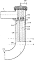
Fig. 7 representes another embodiment of sprayer unit, and this sprayer unit can be used for embodiment for example shown in Figure 5.Crust component 142 has tubular form, and its exit end is directed as required.In solution illustrated in the accompanying drawings because the curved shape of shell 142, outlet port 152 with respect to gun hose 128 with 90 ° angular orientation almost.The other with dashed lines of accompanying drawing be presented at maybe cause clogging situation under the variation L-L ' of liquid surface level.
Injector device of the present invention comprises that at least one injector nozzle 122 sprays into gun hose 128 wherein with at least one injector nozzle, and the path that is used for second medium is introduced injector nozzle 122.This device comprises and is used for strengthening as required the generation means for applying negative, and its mode is through restriction gas, and from the far-end 129 with respect to the injection direction of working medium, promptly the exit end 129 from gun hose flows into the gun hoses 128 such as air.
According to embodiment, housing parts 142 has been arranged in around the gun hose and has had at least one and has been formed at the opening 144 on the shell.In a second embodiment, shell 142 is provided with in addition and is used to cut off or the device 145 of the stream of restricted passage opening 144.In one embodiment, opening 144 is set on shell 142 in the zone between the bottom of top and gun hose 128 of shell.
Be formed in the bottom of shell 142 is to be used to discharge the working medium of eductor and/or the opening 152 that removal is transferred material.
What combine with opening 144 to be provided with is to be used to cut off and/or the check valve element 145 of the stream of restricted passage opening 144.
In yet another embodiment, the device that is used for boot media stream and opening 152 combine to be arranged on the bottom of shell 142.
According to preferred embodiment, this device comprises that the exit end 129 that is used at least where necessary gun hose 128 places near the device that is lower than the liquid level of liquid surface level L, L ' injection device.In common two at least one, or liquid level and/or gun hose move each other.Injector device according to Fig. 6 and 7 can be used as vacuum generator in the application scenario of many type needs negative pressure.
Use equipment of the present invention, the degree of vacuum that is produced by this equipment can obtain to significantly improve.In the embodiment of solution of the present invention, degree of vacuum has been about 0.3-0.4 crust usually, and the method and apparatus of the application of the invention even reached the degree of vacuum of about 0.9 crust.To it is also noted that above-mentioned vacuum values only is an example, therefore, accessible vacuum values can change according to the setting range of system to some extent.
Liquid, aqueous through using as working medium and jetting fluid mist, injector device is obtained very effective solution.In this article, the liquid mist refers to the spraying of Dv50<1000 micron, and promptly average droplet size is less than 1mm.In some cases, the drop size of liquid mist (Dv90) even can be significantly littler is lower than 200 μ m.When needing, working medium can be with high-pressure injection, be preferably the 10-300 crust, but in some cases in addition lower pressure also be applicatory.Usually, can the working pressure scope than the pressure in the lower part, for example the 10-50 crust is preferably the 15-30 crust.Compare with pneumatically-operated eductor, obtained energy-conservation requirement up to 50%.In addition, this system is considerably durable, compares its longer service life with the vacuum pump that is used to produce negative pressure equally.
The background technology of method and apparatus of the present invention was for example touched upon at specification sheets WO 2005/085105 and in specification sheets WO 2005/085104.
The present invention can be applied to the conveying of wide variety of materials.Favourable application also finds to be used for the waste material that conveying machinery industry produces, and such as the residual processing thing, is preferably in the system of fragment.
Injector device of the present invention can use with multiple delivery system incorporates very widely.In addition, injector device can also be more at large as vacuum generator, and with the application scenario that needs negative pressure, such as for instance, timber dryer, suction grasper, fume removal system, dust pelletizing system are used in combination.Injector device is very suitable for being used in combination with the explosibility material.
It will be apparent to those skilled in the art that to the invention is not restricted to the foregoing description, but can in the scope of following claim, change.Already mentioned characteristics also can be used together with other characteristics in case of necessity independently of one another in this specification sheets.
Claims (19)
1. one kind is used for through applying the method that pressure reduction is carried material at delivery conduit (4); In this method, material is admitted in the delivery conduit (4) and in this delivery conduit, further gets into disengagement gear (5), in said disengagement gear; Material that is transferred and conveying air separation; In this method, the injection device (6) that is connected to disengagement gear (5) by means of the suction side produces negative pressure in delivery conduit (4), and said injection device uses the working medium that comprises the liquid mist and operated; Said working medium is imported in the gun hose (128) in the breakaway-element (38) by spirt through at least one injection nozzle (122); It is characterized in that working medium is sprayed in housing parts (142) inside and extends in the gun hose (128) in the breakaway-element (38), the liquid in the breakaway-element (38) has liquid surface level (L, L '); Through limiting gas from the direction opposite with the injection direction of its working medium; Promptly the exit end (129) from gun hose flows into the gun hose (128), and strengthens the generation of the negative pressure that will produce as required, and delivering gas passes the exit opening (144) of housing parts (142).
2. method according to claim 1 is characterized in that, places liquid surface level (L, L ') to limit gas to get off through the above-mentioned exit end with gun hose (128) and gets into gun hose (128) from exit end (129).
3. method according to claim 1 is characterized in that, the exit end of gun hose (129) is placed in the liquid level below the said liquid surface level (L, L ') through liquid surface level in the adjustment breakaway-element.
4. method according to claim 1 is characterized in that, under the situation that in delivery conduit (4,7), occurs blocking, the air-flow that gets at least in housing parts (142) volume inside is limited.
5. method according to claim 4 is characterized in that, air-flow is limited by means of closure member (145).
6. method according to claim 4 is characterized in that, air communication is crossed housing parts (142) the in-to-in liquid surface level (L, L ') and being limited of raising at least.
7. method according to claim 1 is characterized in that material to be carried comprises the discrete material in the food industry,, butchers chip or food waste that is, and material perhaps to be carried comprises the residual processing thing in the mechanical industry.
8. equipment, said equipment is used for carrying material through applying pressure reduction at delivery conduit (4); Said equipment comprises materials conveyance conduit (4), disengagement gear (5) and is used for producing means for applying negative through the injection device (6) that uses the suction side to be connected to disengagement gear (5) at delivery conduit (4); Said injection device is operated by working medium; Said injection device (6) comprises at least one nozzle (121) and at least one injector nozzle (122) that is used for the jetting fluid mist and is used for the liquid mist is used as the working medium of eductor; And comprise the device (125,126,127,131) that is used for liquid is supplied to nozzle; Said at least one injector nozzle (122) be arranged in the gun hose (128) or near; Said gun hose guiding breakaway-element (38) and extending in the breakaway-element (38); It is characterized in that; Said equipment is provided with housing parts (142), and gun hose (128) extends in the said housing parts, and the liquid in the breakaway-element (38) has liquid surface level (L, L '); And this equipment comprise be used for through restriction gas from respect to the gun hose far-end (129) of the injection direction of working medium, promptly flow into gun hose (128) and strengthen the means for applying negative that will produce as required from the exit end of gun hose, and said housing parts is provided with the exit opening (144) that is used for gas.
9. equipment according to claim 8, this equipment comprise the device that is used at least where necessary the exit end (129) of gun hose (128) being placed the liquid level below the liquid surface level (L, L ').
10. equipment according to claim 8 is characterized in that, this equipment comprises the closure member of arranging in combination with exit opening (144) (145).
11. equipment according to claim 10 is characterized in that, closure member (145) is a check valve element.
12. equipment according to claim 8 is characterized in that, this equipment comprises the device that is used for producing at breakaway-element (38) the liquid in rotation motion.
13. equipment according to claim 8 is characterized in that, this equipment comprises the device (38) that is used for from air-flow separating liquid and/or solid material.
14. equipment according to claim 8 is characterized in that, this equipment comprises the device that is used for adjusting breakaway-element liquid surface level (L, L ').
15. equipment according to claim 8 is characterized in that, this equipment comprises that the exit end (129) that is used for as required gun hose (128) places the device below the liquid surface level (L, L ').
16. equipment according to claim 8 is characterized in that, this equipment comprises and is used for adjusting liquid surface level (L, L ') and it is kept the device of desired height at breakaway-element (38).
17. equipment according to claim 8 is characterized in that, this equipment comprises and is used for through adjustment breakaway-element (38) liquid surface level height the exit end (129) of gun hose being placed the following device of liquid surface level (L, L ').
18. equipment according to claim 8 is characterized in that, material to be carried comprises the discrete material in the food industry,, butchers chip and food waste that is, and material perhaps to be carried comprises the residual processing thing in the mechanical industry.
19. equipment according to claim 8 is characterized in that, this equipment comprises that the exit end (129) that is used under the situation that delivery conduit (4,7) occur to block gun hose (128) places the device below the liquid surface level (L, L ').
Applications Claiming Priority (3)
| Application Number | Priority Date | Filing Date | Title |
|---|---|---|---|
| FI20051262A FI118043B (en) | 2005-03-02 | 2005-12-07 | Conveying of material, such as food-industry bulk material, preferably offals or food waste, comprises feeding material to conveying pipe, and conveying pipe to separator device |
| FI20051262 | 2005-12-07 | ||
| PCT/FI2006/000115 WO2007065966A1 (en) | 2005-12-07 | 2006-04-13 | Method and apparatus for conveying material and ejector apparatus |
Related Child Applications (1)
| Application Number | Title | Priority Date | Filing Date |
|---|---|---|---|
| CN2012102884718A Division CN102774657A (en) | 2005-12-07 | 2006-04-13 | Method and apparatus for conveying material and ejector apparatus |
Publications (2)
| Publication Number | Publication Date |
|---|---|
| CN101351395A CN101351395A (en) | 2009-01-21 |
| CN101351395B true CN101351395B (en) | 2012-11-07 |
Family
ID=38122519
Family Applications (2)
| Application Number | Title | Priority Date | Filing Date |
|---|---|---|---|
| CN2006800460846A Expired - Fee Related CN101351395B (en) | 2005-12-07 | 2006-04-13 | Method and apparatus for conveying material and ejector apparatus |
| CN2012102884718A Pending CN102774657A (en) | 2005-12-07 | 2006-04-13 | Method and apparatus for conveying material and ejector apparatus |
Family Applications After (1)
| Application Number | Title | Priority Date | Filing Date |
|---|---|---|---|
| CN2012102884718A Pending CN102774657A (en) | 2005-12-07 | 2006-04-13 | Method and apparatus for conveying material and ejector apparatus |
Country Status (17)
| Country | Link |
|---|---|
| US (3) | US7785044B2 (en) |
| EP (2) | EP1957386B1 (en) |
| JP (1) | JP5323490B2 (en) |
| KR (1) | KR101303425B1 (en) |
| CN (2) | CN101351395B (en) |
| AT (1) | ATE486032T1 (en) |
| AU (1) | AU2006323883B2 (en) |
| CA (1) | CA2629606C (en) |
| DE (1) | DE602006017875D1 (en) |
| DK (2) | DK1957386T3 (en) |
| ES (2) | ES2390825T3 (en) |
| HK (1) | HK1117120A1 (en) |
| NO (2) | NO339627B1 (en) |
| PL (2) | PL1957386T3 (en) |
| PT (2) | PT2184241E (en) |
| RU (1) | RU2395442C2 (en) |
| WO (1) | WO2007065966A1 (en) |
Families Citing this family (20)
| Publication number | Priority date | Publication date | Assignee | Title |
|---|---|---|---|---|
| GB0523338D0 (en) * | 2005-11-16 | 2005-12-28 | Inbulk Technologies Ltd | Vacuum conveying velocity control device |
| EP1957386B1 (en) * | 2005-12-07 | 2010-10-27 | Maricap OY | Method and apparatus for conveying material and ejector apparatus |
| FI122682B (en) * | 2007-09-18 | 2012-05-31 | Maricap Oy | Waste shipment system |
| FI20075749L (en) * | 2007-10-24 | 2009-04-25 | Maricap Oy | Method and equipment in a material vacuum transfer system |
| FI124436B (en) * | 2008-03-18 | 2014-08-29 | Maricap Oy | Method and equipment in a pneumatic material transfer system |
| FI124873B (en) * | 2009-10-06 | 2015-02-27 | Maricap Oy | Method and apparatus in a pneumatic material transport system |
| FI122103B (en) * | 2010-03-12 | 2011-08-31 | Maricap Oy | Method and apparatus in a pneumatic material transport system and waste transport system |
| FI122673B (en) | 2010-11-01 | 2012-05-15 | Maricap Oy | Procedure and plant in a pneumatic material transport system |
| FI123342B (en) * | 2011-06-08 | 2013-02-28 | Maricap Oy | Method and equipment in a pneumatic material transfer system |
| FI123719B (en) * | 2012-03-21 | 2013-10-15 | Maricap Oy | Method and apparatus for treating the exhaust air from a pneumatic waste transport system |
| RU2535821C1 (en) * | 2013-10-31 | 2014-12-20 | Закрытое Акционерное Общество "Твин Трейдинг Компани" | Air vacuum device for transfer of loose materials with high weight concentration |
| WO2015072935A1 (en) * | 2013-11-15 | 2015-05-21 | Yi̇ği̇tler Teksti̇l İnşaat Ve Turi̇zm A.Ş. | Cotton feeding unit |
| US10138075B2 (en) * | 2016-10-06 | 2018-11-27 | Stephen B. Maguire | Tower configuration gravimetric blender |
| US9725254B2 (en) * | 2014-08-21 | 2017-08-08 | Cnh Industrial Canada, Ltd. | Configurations of inlet and outlets of air filled auxiliary tank of air seeders |
| US9950876B2 (en) * | 2014-09-26 | 2018-04-24 | Cnh Industrial Canada, Ltd. | Downward elbow with cyclonic effect and product overflow capability |
| EP3100968A1 (en) * | 2015-06-01 | 2016-12-07 | Xerex Ab | Device and system for pneumatic transport of material |
| EP3530599A1 (en) * | 2018-02-27 | 2019-08-28 | Piab Ab | Vacuum conveyor system |
| FI129115B (en) * | 2020-01-14 | 2021-07-15 | Maricap Oy | Method for conveying material in a pneumatic material conveying system, and pneumatic material conveying system |
| EP3882185B1 (en) * | 2020-03-19 | 2023-11-22 | ImerTech SAS | Pumping apparatus |
| KR102610699B1 (en) * | 2022-02-18 | 2023-12-06 | 에스케이온 주식회사 | Vacuum type powder transfer system and method thereof |
Citations (4)
| Publication number | Priority date | Publication date | Assignee | Title |
|---|---|---|---|---|
| CN1079542A (en) * | 1993-03-06 | 1993-12-15 | 胜利石油管理局东辛采油厂 | Oil-gas closed mixed transmission method and transfer station |
| US6017195A (en) * | 1993-02-12 | 2000-01-25 | Skaggs; Bill D. | Fluid jet ejector and ejection method |
| CN1676920A (en) * | 2004-03-31 | 2005-10-05 | 三菱扶桑卡客车公司 | Fuel jetting device |
| WO2005085104A9 (en) * | 2004-03-03 | 2005-11-10 | Maricap Oy | Method and apparatus for conveying material |
Family Cites Families (20)
| Publication number | Priority date | Publication date | Assignee | Title |
|---|---|---|---|---|
| US870981A (en) * | 1906-01-15 | 1907-11-12 | Frank J Matchette | Vacuum cleaning system. |
| US1965866A (en) * | 1933-04-19 | 1934-07-10 | Jr Edgar B Tolman | Fluid actuated control device for pneumatic conveyers |
| US2992858A (en) * | 1958-12-02 | 1961-07-18 | Vac U Max | System for conveying fluent material |
| US3874860A (en) * | 1972-04-10 | 1975-04-01 | Svenska Flaektfabriken Ab | Apparatus for separating particulate matter from a flowing medium |
| US4595344A (en) * | 1982-09-30 | 1986-06-17 | Briley Patrick B | Ejector and method of controlling same |
| JPS6093034A (en) | 1984-07-11 | 1985-05-24 | 共栄造機株式会社 | Solids transport device |
| US4685840A (en) * | 1985-08-02 | 1987-08-11 | Wolff Robert C | Method of transporting large diameter particulate matter |
| FI76242B (en) | 1986-08-27 | 1988-06-30 | Tuottajain Lihakeskuskunta | FOERFARANDE OCH ANORDNING FOER TRANSPORT AV KOETTSORTIMENT I EN KANAL MEDELST TRYCKDIFFERENS. |
| US5765728A (en) * | 1995-03-27 | 1998-06-16 | Eastman Kodak Company | Method and apparatus for feeding chopped polyester scrap |
| EP0937004B2 (en) * | 1996-10-22 | 2006-10-11 | Dietrich Engineering Consultants S.A. | Process and device for pneumatically conveying powdery substances |
| US6361201B1 (en) * | 1999-06-04 | 2002-03-26 | Dialysis Systems, Inc. | Centralized bicarbonate mixing system |
| JP3908447B2 (en) * | 2000-08-11 | 2007-04-25 | 株式会社荏原製作所 | Ejector |
| JP2003056500A (en) * | 2001-08-20 | 2003-02-26 | Keiji Takuwa | Ejector |
| US6537036B1 (en) * | 2001-09-13 | 2003-03-25 | Illinois Tool Works | Flow amplifying pump apparatus |
| US6634833B2 (en) * | 2001-11-30 | 2003-10-21 | Pneumatic Conveying, Inc. | Pneumatic conveying apparatus |
| US6817837B2 (en) * | 2002-07-19 | 2004-11-16 | Walker-Dawson Interest, Inc. | Jet pump with recirculating motive fluid |
| US7789633B2 (en) | 2003-06-23 | 2010-09-07 | George Tash and Debra B. Tash | Automatically deformable nozzle regulator for use in a venturi pump |
| ATE356065T1 (en) * | 2003-06-23 | 2007-03-15 | Mann & Hummel Protec Gmbh | VACUUM TANK WITH ACTIVE QUICK EMPTY VALVE CONTROL |
| US6976854B2 (en) * | 2003-10-17 | 2005-12-20 | Andreas Stockhaus | Arrangement for connecting the terminal contacts of an electronic component to a printed circuit board and conductor support for such an arrangement |
| EP1957386B1 (en) * | 2005-12-07 | 2010-10-27 | Maricap OY | Method and apparatus for conveying material and ejector apparatus |
-
2006
- 2006-04-13 EP EP06725876A patent/EP1957386B1/en active Active
- 2006-04-13 DK DK06725876.4T patent/DK1957386T3/en active
- 2006-04-13 PL PL06725876T patent/PL1957386T3/en unknown
- 2006-04-13 ES ES10151748T patent/ES2390825T3/en active Active
- 2006-04-13 DE DE602006017875T patent/DE602006017875D1/en active Active
- 2006-04-13 KR KR1020087016494A patent/KR101303425B1/en active IP Right Grant
- 2006-04-13 EP EP10151748A patent/EP2184241B1/en not_active Not-in-force
- 2006-04-13 AU AU2006323883A patent/AU2006323883B2/en not_active Ceased
- 2006-04-13 PT PT10151748T patent/PT2184241E/en unknown
- 2006-04-13 RU RU2008127352/11A patent/RU2395442C2/en active
- 2006-04-13 AT AT06725876T patent/ATE486032T1/en active
- 2006-04-13 CA CA2629606A patent/CA2629606C/en active Active
- 2006-04-13 PL PL10151748T patent/PL2184241T3/en unknown
- 2006-04-13 CN CN2006800460846A patent/CN101351395B/en not_active Expired - Fee Related
- 2006-04-13 WO PCT/FI2006/000115 patent/WO2007065966A1/en active Application Filing
- 2006-04-13 PT PT06725876T patent/PT1957386E/en unknown
- 2006-04-13 ES ES06725876T patent/ES2354170T3/en active Active
- 2006-04-13 DK DK10151748.0T patent/DK2184241T3/en active
- 2006-04-13 CN CN2012102884718A patent/CN102774657A/en active Pending
- 2006-04-13 US US12/085,339 patent/US7785044B2/en active Active
- 2006-04-13 JP JP2008543857A patent/JP5323490B2/en not_active Expired - Fee Related
-
2008
- 2008-07-03 NO NO20082952A patent/NO339627B1/en not_active IP Right Cessation
- 2008-11-07 HK HK08112256.6A patent/HK1117120A1/en unknown
-
2010
- 2010-06-09 US US12/797,110 patent/US7896584B2/en not_active Expired - Fee Related
- 2010-06-09 US US12/797,195 patent/US7891954B2/en not_active Expired - Fee Related
-
2016
- 2016-09-20 NO NO20161506A patent/NO20161506A1/en not_active Application Discontinuation
Patent Citations (4)
| Publication number | Priority date | Publication date | Assignee | Title |
|---|---|---|---|---|
| US6017195A (en) * | 1993-02-12 | 2000-01-25 | Skaggs; Bill D. | Fluid jet ejector and ejection method |
| CN1079542A (en) * | 1993-03-06 | 1993-12-15 | 胜利石油管理局东辛采油厂 | Oil-gas closed mixed transmission method and transfer station |
| WO2005085104A9 (en) * | 2004-03-03 | 2005-11-10 | Maricap Oy | Method and apparatus for conveying material |
| CN1676920A (en) * | 2004-03-31 | 2005-10-05 | 三菱扶桑卡客车公司 | Fuel jetting device |
Also Published As
Similar Documents
| Publication | Publication Date | Title |
|---|---|---|
| CN101351395B (en) | Method and apparatus for conveying material and ejector apparatus | |
| KR20070011355A (en) | Method and apparatus for conveying material | |
| JP2009518256A5 (en) | ||
| CN214114208U (en) | Pollutant conveying and transferring system driven by compressed gas | |
| CN203639744U (en) | Dry screen cleaning device | |
| FI118043B (en) | Conveying of material, such as food-industry bulk material, preferably offals or food waste, comprises feeding material to conveying pipe, and conveying pipe to separator device | |
| CN215586835U (en) | Powder sprayer driven by compressed gas | |
| CN112093482B (en) | Pollutant conveying and transferring system driven by compressed gas | |
| CN112108284A (en) | Powder sprayer driven by compressed gas | |
| FI118893B (en) | Conveying of material, such as food-industry bulk material, preferably offals or food waste, comprises feeding material to conveying pipe, and conveying pipe to separator device |
Legal Events
| Date | Code | Title | Description |
|---|---|---|---|
| C06 | Publication | ||
| PB01 | Publication | ||
| C10 | Entry into substantive examination | ||
| SE01 | Entry into force of request for substantive examination | ||
| C14 | Grant of patent or utility model | ||
| GR01 | Patent grant | ||
| CF01 | Termination of patent right due to non-payment of annual fee |
Granted publication date: 20121107 |