CN101276172B - Image reading apparatus - Google Patents
Image reading apparatus Download PDFInfo
- Publication number
- CN101276172B CN101276172B CN2008100874471A CN200810087447A CN101276172B CN 101276172 B CN101276172 B CN 101276172B CN 2008100874471 A CN2008100874471 A CN 2008100874471A CN 200810087447 A CN200810087447 A CN 200810087447A CN 101276172 B CN101276172 B CN 101276172B
- Authority
- CN
- China
- Prior art keywords
- original copy
- leader
- image
- stayed surface
- movable
- Prior art date
- Legal status (The legal status is an assumption and is not a legal conclusion. Google has not performed a legal analysis and makes no representation as to the accuracy of the status listed.)
- Active
Links
- 238000000926 separation method Methods 0.000 claims description 10
- 238000000465 moulding Methods 0.000 claims description 3
- 239000002184 metal Substances 0.000 claims description 2
- 230000008602 contraction Effects 0.000 claims 1
- 239000011521 glass Substances 0.000 description 37
- 239000000463 material Substances 0.000 description 10
- 238000000034 method Methods 0.000 description 7
- 238000010586 diagram Methods 0.000 description 6
- 239000005357 flat glass Substances 0.000 description 3
- 230000000994 depressogenic effect Effects 0.000 description 2
- 238000007667 floating Methods 0.000 description 2
- 238000011144 upstream manufacturing Methods 0.000 description 2
- 238000005452 bending Methods 0.000 description 1
- 238000001514 detection method Methods 0.000 description 1
- 238000005516 engineering process Methods 0.000 description 1
- 239000003292 glue Substances 0.000 description 1
- 230000003760 hair shine Effects 0.000 description 1
- 238000005286 illumination Methods 0.000 description 1
- 230000013011 mating Effects 0.000 description 1
- 238000002360 preparation method Methods 0.000 description 1
- 230000008961 swelling Effects 0.000 description 1
- 238000010023 transfer printing Methods 0.000 description 1
Images


Classifications
-
- H—ELECTRICITY
- H04—ELECTRIC COMMUNICATION TECHNIQUE
- H04N—PICTORIAL COMMUNICATION, e.g. TELEVISION
- H04N1/00—Scanning, transmission or reproduction of documents or the like, e.g. facsimile transmission; Details thereof
- H04N1/04—Scanning arrangements, i.e. arrangements for the displacement of active reading or reproducing elements relative to the original or reproducing medium, or vice versa
- H04N1/12—Scanning arrangements, i.e. arrangements for the displacement of active reading or reproducing elements relative to the original or reproducing medium, or vice versa using the sheet-feed movement or the medium-advance or the drum-rotation movement as the slow scanning component, e.g. arrangements for the main-scanning
- H04N1/121—Feeding arrangements
- H04N1/123—Using a dedicated sheet guide element
-
- H—ELECTRICITY
- H04—ELECTRIC COMMUNICATION TECHNIQUE
- H04N—PICTORIAL COMMUNICATION, e.g. TELEVISION
- H04N1/00—Scanning, transmission or reproduction of documents or the like, e.g. facsimile transmission; Details thereof
- H04N1/04—Scanning arrangements, i.e. arrangements for the displacement of active reading or reproducing elements relative to the original or reproducing medium, or vice versa
- H04N1/12—Scanning arrangements, i.e. arrangements for the displacement of active reading or reproducing elements relative to the original or reproducing medium, or vice versa using the sheet-feed movement or the medium-advance or the drum-rotation movement as the slow scanning component, e.g. arrangements for the main-scanning
- H04N1/121—Feeding arrangements
- H04N1/1235—Feeding a sheet past a transparent plate; Details thereof
-
- H—ELECTRICITY
- H04—ELECTRIC COMMUNICATION TECHNIQUE
- H04N—PICTORIAL COMMUNICATION, e.g. TELEVISION
- H04N1/00—Scanning, transmission or reproduction of documents or the like, e.g. facsimile transmission; Details thereof
- H04N1/04—Scanning arrangements, i.e. arrangements for the displacement of active reading or reproducing elements relative to the original or reproducing medium, or vice versa
- H04N1/10—Scanning arrangements, i.e. arrangements for the displacement of active reading or reproducing elements relative to the original or reproducing medium, or vice versa using flat picture-bearing surfaces
- H04N1/1013—Scanning arrangements, i.e. arrangements for the displacement of active reading or reproducing elements relative to the original or reproducing medium, or vice versa using flat picture-bearing surfaces with sub-scanning by translatory movement of at least a part of the main-scanning components
-
- H—ELECTRICITY
- H04—ELECTRIC COMMUNICATION TECHNIQUE
- H04N—PICTORIAL COMMUNICATION, e.g. TELEVISION
- H04N1/00—Scanning, transmission or reproduction of documents or the like, e.g. facsimile transmission; Details thereof
- H04N1/04—Scanning arrangements, i.e. arrangements for the displacement of active reading or reproducing elements relative to the original or reproducing medium, or vice versa
- H04N1/19—Scanning arrangements, i.e. arrangements for the displacement of active reading or reproducing elements relative to the original or reproducing medium, or vice versa using multi-element arrays
- H04N1/191—Scanning arrangements, i.e. arrangements for the displacement of active reading or reproducing elements relative to the original or reproducing medium, or vice versa using multi-element arrays the array comprising a one-dimensional array, or a combination of one-dimensional arrays, or a substantially one-dimensional array, e.g. an array of staggered elements
- H04N1/192—Simultaneously or substantially simultaneously scanning picture elements on one main scanning line
- H04N1/193—Simultaneously or substantially simultaneously scanning picture elements on one main scanning line using electrically scanned linear arrays, e.g. linear CCD arrays
-
- H—ELECTRICITY
- H04—ELECTRIC COMMUNICATION TECHNIQUE
- H04N—PICTORIAL COMMUNICATION, e.g. TELEVISION
- H04N2201/00—Indexing scheme relating to scanning, transmission or reproduction of documents or the like, and to details thereof
- H04N2201/0077—Types of the still picture apparatus
- H04N2201/0081—Image reader
Abstract
An image reading apparatus has a reading portion configured to read the image of the original at the reading position located on a supporting surface for supporting the original, an original feeding portion configured to convey an original to the reading position, a movable guide portion which faces the supporting surface and guides the original conveyed by the original conveying portion to the reading position, and a biasing member configured to apply a biasing force to the guide portion toward the supporting surface, wherein the movable guide portion has a rib portion, the rib portion projects toward the supporting surface and is formed along the original conveying direction, and the rib portion presses an original, that is read by the reading portion while the original is conveyed by the conveying portion, to the supporting surface by the biasing force of the biasing member.
Description
Technical field
The present invention relates to be used to read image-reading device that is transferred original copy information and the image forming apparatus that adopts this image-reading device.
Background technology
During by the image-reading device reading images, picture original must read the position and pressuring plate glass is close to.For this reason, as shown in figure 12, traditional image-reading device has the blank of reading 101, is reading the position and pressuring plate glass 100 is close to be used to make original copy S.
In order to prevent that reliably original copy from reading floating of position, proposed the upstream that on throughput direction original copy reads the position flexible board parts 102 had been set, be used for preventing the interference that image reads, thereby improve the precision (patent document 1: Japanese Unexamined Patent Publication No 2003-051915) that reads.
But, for said structure, because original copy is compressed by plate member 102, so the surface in contact between plate member and the original copy becomes greatly.Therefore, the frictional noise that is produced by plate member and original copy may be quite big.Improve under the situation of original copy snap-in force in order to improve the precision that reads, when the quantity of plate member 102 increases at the original copy Width, or the width of plate member 102 is when increasing, and frictional noise also may be bigger.
For said structure, because plate member 102 compresses original copy always, so the rear end of original copy during through plate member 102, the load that is applied on the original copy is released, thereby sometimes load fluctuation takes place.Because load fluctuation takes place, the reading precision and will reduce of original image, perhaps original copy can be flapped and be produced noise.
Summary of the invention
Consider that above-mentioned situation has proposed the present invention, the invention provides image-reading device and image forming apparatus, wherein to read precision splendid for image, comes from the noise that is transferred original copy simultaneously and be reduced.
The image-reading device of the present invention that is used to solve foregoing problems has following characteristics, and this equipment has reading section, is used to read the image that is positioned at the original copy that reads the position on the stayed surface that supports original copy; Original copy feeding part is used for original copy is transported to and reads the position; Movable leader, it directs in the face of described stayed surface and the original copy of partly being carried by described original copy feeding and reads the position; And biasing member, be used for biasing force is applied to described leader towards described stayed surface; Wherein, described movable leader has flank, this flank protrudes and forms along the original copy throughput direction towards described stayed surface, and the biasing force of this flank by described biasing member is pressed onto the original copy that is read by described reading section on the described stayed surface when original copy is partly carried by described original copy feeding.
In addition, image-reading device of the present invention is the image-reading device with following characteristics, and this equipment has reading section, and this reading section is used to read the image that is positioned at the original copy that reads the position on the stayed surface that supports original copy; Original copy feeding part, this original copy feeding partly are used for original copy is transported to and read the position; Leader, this leader direct in the face of described stayed surface and the original copy of partly being carried by described original copy feeding and read the position; And movable part, this movable part moves described leader between compacted position and separation point position, when compacted position original copy is pressed onto on the described stayed surface, and the separation point position ratio compresses the position from described stayed surface separation De Gengkai.
Equipment provided by the invention can reduce to come from the noise that is transferred original copy, and reads the precision height.
By below with reference to the explanation of accompanying drawing, can understand more features of the present invention to embodiment.
Description of drawings
Fig. 1 is the enlarged drawing that expression is transferred manuscript reading section.
The key diagram that Fig. 2 is wherein reads blank and looks from the original copy throughput direction.
Fig. 3 is the key diagram of expression according to the image-reading device feature of first embodiment.
Shown in Figure 4 is the whole schematic illustration with image forming apparatus of image-reading device.
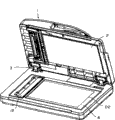
Shown in Figure 5 is the illustrative perspective view of the image-reading device seen from upside.
Shown in Figure 6 is the illustrative perspective view that the pressing plate of the image-reading device seen from upside is in open mode.
Fig. 7 is the main cross-sectional view of the illustrative of presentation video fetch equipment.
Shown in Figure 8 is the illustrative perspective view of the compacting part of foundation second embodiment.
Shown in Figure 9 is the illustrative cross section of the image reading section of foundation second embodiment.
Figure 10 is the illustrative perspective view that expression high molecular actuator 19,23 is in swelling state.
Shown in Figure 11 is the illustrative cross section of this state.
Shown in Figure 12 is the explanation view of prior art.
Shown in Figure 13 is process flow diagram, is used for illustrating the operation of the second embodiment control part.
Embodiment
Below, image-reading device according to an embodiment of the invention will be described, for example understand image forming apparatus with this image-reading device.
[first embodiment]
Fig. 1 to shown in Figure 7 be image-reading device and image forming apparatus according to first embodiment, Fig. 1 is a representational view to Fig. 3, feature according to the image-reading device of first embodiment is shown, in addition, Fig. 4 is the whole schematic illustration with image forming apparatus of image-reading device, and Fig. 5 is the integrally-built key diagram of display image fetch equipment to Fig. 7.
[image forming apparatus]
At first, will image forming apparatus be described with reference to figure 4.The image forming apparatus A of present embodiment has the image-reading device B that is positioned on equipment body 100 tops, and to illustrate as an example as image forming method forms image on sheet material duplicating machine by employing electronic photo image forming method.
Toner image and sheet material are carried synchronously to form on the photosensitive drums parts 105 partly at composing images and are formed.For this reason, be adjacent to be provided with the image forming course device, for example exposure device 106 and developing apparatus 107 with photosensitive drums parts 105.When image forms, light in response to the original copy information that is read by image-reading device B shines on the photosensitive drums parts 105 to form electrostatic image from exposure device 106, and developing by developing apparatus 107 is used for the toner of this electrostatic image, and resulting like this toner image just is transferred on the sheet material that is transferred.
On it transfer printing the sheet material of toner image be transported to fixing device 108, and be heated and pressurization so that toner image.Afterwards, this sheet material is discharged to the outside of equipment by paired distributing roller 109.
[image-reading device]
To Fig. 7 image-reading device is described below with reference to Fig. 5, wherein Fig. 5 is the illustrative perspective view from upside picture fetch equipment with the aid of pictures, Fig. 6 is the illustrative perspective view of seeing from upside, wherein the pressing plate unit of image-reading device is in open mode, and Fig. 7 is the main cross-sectional illustration figure of image-reading device.
As shown in Figure 5 and Figure 6, blank 2 is set in place on the still image reading section on pressing plate unit 1 lower surface, when reading the still image original copy with box lunch, original copy D2 closely contacts with the pressuring plate glass 6 that is transparent component, has therefore constituted the structure that pressing plate unit 1 can be opened and closed around hinge 3.
As shown in Figure 7, the reading part 5 that is transferred original copy has the original copy transport path (back is called " U-shaped detour footpath ") that roughly takes the shape of the letter U.Original copy block 10 is located on the U-shaped detour footpath 7, is used to adjust the front position of the original copy D1 that is deposited on the original copy pallet 4.Be used to carry the parts of original copy D1 to comprise pick-up roller 17, separate roller 8 and separating pad 9, pick-up roller 17 and the uppermost a original copy that is deposited in the original copy D1 on the original copy pallet 4 are against picking up it, and separate roller 8 and separating pad 9 more than are separated also feeding with original copy D1.In addition, the original copy transfer unit comprises conveying roller 13 and a pair of distributing roller 14, wherein, conveying roller 13 is as auto document feeding part, be transported to original copy and read the position, and distributing roller 14 is as the original copy discharge section, to carry by reading the original copy of position feeding.On the original copy transport path, original copy is installed has detecting sensor 11 and document edge sensor 15, they are as the sensor that detects original copy, wherein, original copy exists detecting sensor 11 to detect on the original copy pallet 4 whether have original copy D1, and document edge sensor 15 detects the leading section and the rearward end of the original copy that will carry.
The bottom of reading the position on the original copy transport path is provided with fit type imageing sensor 16, and it is used to read as reading section and is positioned at the original copy that reads the position.This fit type imageing sensor 16 will be mapped to the image information surface of original copy D1 from the illumination as the led array of light source, and the reflected light scioptics in the reflection of image information surface can be focused on the sensor element, with reading images information.
At the reading part 5 that is transferred original copy, when the operator was placed on original copy D1 on the original copy pallet 4, the reading images surface of original copy D1 was positioned at its upside, and operator's side that so just can slave unit is set original copy D1.Whether at this moment, the front position of original copy D1 is adjusted by original copy block 10, and exist detecting sensor 11 detection original copy D1 to exist by original copy.
When beginning to read by operating portion (not shown) instruction by the operator, the rotation of drive part (not shown), therefore, original copy block 10 is depressed, and original copy D1 is transported to separating part between separate roller 8 and the separating pad 9 by pick-up roller 17.Original copy D1 is separated by many, opens and is transferred so that uppermost original copy D1 is separated.The original copy D1 that separates carries along U-shaped detour footpath 7 by conveying roller 13, and further is delivered to the reading section of fit type imageing sensor 16.
In auto document feeding part, after detecting the leading section of original copy D1, when original copy D1 is transported to leave the one section preset distance in this position, begin by fit type imageing sensor 16 reading images information by document edge sensor 15.After beginning to read, original copy is gone to that to distributing roller 14.After the rearward end of original copy D1 is detected by document edge sensor 15, when original copy is transported to leave the one section preset distance in this position, just finish by fit type imageing sensor 16 reading images information.By that distributing roller 14 is discharged to this original copy D1 outside the equipment.
By this way, in the reading part 5 that is transferred original copy, repeat above-mentioned read operation, till original copy exists detecting sensor 11 to detect original copy not exist.
[preventing the original copy floating structure]
In this embodiment, original copy takes place to float reading the position in order to prevent to read original copy, be provided with and compress guiding part 18 (movable leader) and read blank 20 (second leader), wherein compress guiding part 18 and be positioned at the upstream of reading the position, read blank 20 and be used to guide the original copy that reads the position along the original copy throughput direction.This structure that is used for above-mentioned purpose below with reference to Fig. 1 to Fig. 3 explanation.Fig. 1 is the enlarged drawing that is transferred manuscript reading section, and Fig. 2 is a key diagram, wherein reads blank and looks from the original copy throughput direction, and Fig. 3 is the illustrative perspective view of the surrounding structure of original copy compacting part.
[reading the original copy guiding of position]
As shown in Figure 1, be provided with transparent contact glass 12 on the top of fit type imageing sensor 16, it is positioned at the original copy that reads position Y as support component to be used to support, and the original copy that is transferred closely contacts to be read with the supporting surface 12a that contacts glass 12.For this reason, be provided with as second leader read blank 20, to be used for remaining on contact glass 12 with being positioned at the original copy that reads position Y.Read blank 20 and be installed to down swingably on the guiding part 21, and on the direction of contact glass 12, power is applied on this time guiding part by biasing spring 25.Guiding part as the original copy that reads position Y is guided reads 20 pairs of original copys of blank and guides, so that original copy is crushed on the contact glass 12.
As shown in Figure 2, read blank 20 and have bearing part 20a, 20b and separating part 20c, wherein, bearing part 20a, 20b with contact glass 12 perpendicular to the two ends on the original copy Width of original copy throughput direction against, and separating part 20c from the contact glass 12 float about 0.3 to 0.5mm.Bearing part 20a, 20b are located at outside the conveyor zones.Be that bearing part 20a, 20b are provided with dividually in Width and the conveyor zones of carrying original copy.Original copy does not contact glass 12 by the bottom of separating part 20c thereby do not press.Therefore, can reduce stain (for example being bonded at the glue on the original copy) and be attached on the contact glass 12, thereby improve reading of image.
As previously mentioned, by biasing spring 25 power is applied to and reads on the blank 20 towards contact glass 12.But, because the blank 20 that reads of this embodiment is molded parts, therefore when power is applied to the middle part of reading blank 20 by biasing spring 25, the middle part just bending with contact glass 12 and contact.Therefore, in this embodiment, biasing spring 25 is arranged to power is applied to the both ends of reading blank 20.Like this, separating part 20c floats with regard to having prevented the original copy that is transferred, and need not compress original copy, thereby any thing that is bonded on the original copy can not adhere on the contact glass 12.
[compressing guiding part]
As shown in Figure 1, in this embodiment, at the conveying roller on the original copy transport path 13 with read to be provided with between the blank 20 to be used for original copy is pressed in and compress guiding part 18 on the contact glass 12.Compress guiding part 18 and original copy is directed into read the position, and original copy is pressed on the contact glass 12.This compress that guiding part 18 is used to prevent to go to downstream guiding part 24 and be positioned at contact glass 12 downstreams when the front end of original copy that during to distributing roller 14 owing to original copy reads the big image drift that flapping of position Y causes at original copy.
Compress guiding part 18 movably by guiding part 21 supports down.Compressing guiding part 18 is moulding parts.Concrete is, as shown in Figure 3, the protruding mating part 18c that compresses guiding part 18 rotatably is installed to down the bossing 21a of guiding part 21, and also has similar structure to A portion that they are faced.Therefore, compressing guiding part 18 is supported on down on the guiding part 21 pivotally.Apply power towards contact glass 12 toward compressing on the guiding part 18 by biasing spring 22 as biasing device.
As shown in Figure 3, on a plurality of parts that compress guiding part 18 on the original copy Width, have flank 18d, the 18e that gives prominence to contact glass 12.These flanks 18d, 18e form along the throughput direction of original copy.These flanks 18d, 18e have crooked shape so that original copy is directed into contact glass 12, and flank 18d, 18e be configured to contact glass 12 against, and other parts not with contact glass against.In addition, flank 18d, 18e along the shape of original copy throughput direction comprise to the original copy throughput direction tilt and with the uneven flank of original copy throughput direction.
The compacted guiding part of carrying by conveying roller 13 18 of original copy directs into contact glass 12, and is pressed onto on the contact glass 12 by flank 18d, 18e.Therefore, even original copy is thicker, it can not float from contact glass 12 yet, thereby has prevented that original copy from flapping, thereby can reduce at the image drift that reads position Y.Because the contact area between flank 18d, 18e and the original copy is very little, therefore just reduced the frictional noise that produces by flank and original copy.
Therefore, under the situation that does not increase the biasing force that reads blank 20 and compress guiding part 18, prevented flapping of original copy, and reduced frictional noise.
In the above-mentioned explanation, compress the biasing force of guiding part 18 by biasing spring 22 original copy is pressed on the contact glass 12.But, also can constitute make compress guiding part 18 by the weight that compresses guiding part 18 without the spring handle original copy be pressed in the contact glass 12 on.
[second embodiment]
Below, will be with reference to the equipment of figure 8 to Figure 11 explanations according to second embodiment.Because the basic structure of this embodiment equipment is identical with the basic structure of previous embodiment, therefore no longer carry out repeat specification, only introduce the structure that embodies the present embodiment characteristic here.Identical Reference numeral represent to have with previous embodiment in the parts of identical function.
Present embodiment is different with previous embodiment be in: compress guiding part 18 with contact glass 12 be configured to them can be against each other, and compress guiding part 18 can be according to the feed status of original copy and separately from contact glass 12.
For this reason,, be provided with moving-member as Fig. 8 and shown in Figure 9, its be used to allow biased spring 22 apply power and with contact glass 12 against the guiding part 18 that compresses move, compress guiding part 18 and contact glass 12 separately thereby make.Fig. 8 is the explanation skeleton view according to the compacting part of second embodiment, and Fig. 9 is the illustrative viewgraph of cross-section according to the image reading section of second embodiment.
As Fig. 8 and shown in Figure 9, compress guiding part 18 and have swing adjustment member 18a, 18b, and the curved distal end of swing adjustment member 18a, 18b engages with following guiding part 21.As the high molecular actuator 19,23 of movable part between the curved end and following guiding part 21 of swing adjustment member 18a, 18b.The characteristics of these high molecular actuators 19,23 are to expand and shrink by applying voltage, and the characteristics of the high molecular actuator that adopts of this embodiment are to expand when applying positive voltage, shrink when applying negative voltage.These actuators can adopt the complex of high molecular body and metal to make.The voltage that is applied to the high molecular actuator is by control part 777 controls.
Fig. 8 and shown in Figure 9 be that high molecular actuator 19,23 is in the state when shrinking.Under this state, apply power compressing on the guiding part 18 by biasing spring 22, and flank 18d, 18e be in can with contact glass 12 against compacted position.
State when the illustrative perspective view of Figure 10 is represented 19,23 expansions of high molecular actuator, Figure 11 is the illustrative viewgraph of cross-section of this state.As shown in Figure 10 and Figure 11, when applying positive voltage on high molecular actuator 19,23, high molecular actuator 19,23 just expands.Therefore, swing adjustment member 18a, 18b are pulled upwardly, simultaneously flank 18d, 18e is in contact the separation point position that glass 12 is separated.Here, the bulging force of high molecular actuator 19,23 is greater than the biasing force of biasing spring 22, and the biasing force that high molecular actuator 19,23 allows swing adjustment member 18a, 18b to overcome biasing spring 22 moves to the separation point position.
As mentioned above, compress guiding part 18 can against contact glass 12 and can with contact this structure that glass 12 separates, in this embodiment, at first, on high molecular actuator 19,23, apply negative voltage, arrive at that to distributing roller 14 up to the original copy front end that is transferred.That is, when the signal that begins to read when operating portion is input to control part 777, control part 777 is applied to negative voltage on the high molecular actuator 19,23.Therefore, shown in Fig. 8 and 9, high molecular actuator 19,23 shrinks so that flank 18d, 18e with contact glass 12 against, contact on the glass 12 thereby allow the original copy that is transferred to be depressed in the partial pressure of biasing spring 22.Therefore, prevented that original copy is reading flapping of position Y when the original copy front end enters downstream guiding part 24 and distributing roller 14.
The front end that is transferred original copy arrive that to distributing roller 14 after, on high molecular actuator 19,23, apply positive voltage, up to the rear end of original copy by conveying roller 13.That is, control part 777 is carried out control, so that in response to the signal from document edge sensor 15, before conveying roller 13 is passed through in the rear end of original copy, positive voltage is applied to high molecular actuator 19,23.By this way, shown in Figure 10 and 11, high molecular actuator 19,23 expands, so that flank 18d, 18e are from contact glass 12 separately.Therefore, prevented when the rear end that is transferred original copy when compressing guiding part 18 owing to be applied to the original copy that the load fluctuation on the original copy causes and flap.
Come the control of description control portion 777 below with reference to the process flow diagram of Figure 13.
At first, control part 777 determines whether the signal that begins to read from operating portion (S1) input.If the signal that begins to read is transfused to, control part 777 is carried out control so, negative voltage is applied to high molecular actuator 19,23 (S2).Like this, compress guiding part 18 and be in compacted position.
Then, control part determines whether document edge sensor 15 has detected the original copy (S3) that is transferred.Control part 777 determines whether passed through schedule time T1 (S4) after document edge sensor 15 has detected original copy.Schedule time T1 be set to when the original copy front end arrive that to distributing roller 14 after and the original copy rear end by a period of time before the conveying roller 13.
After having passed through schedule time T1, control part 777 is carried out control, positive voltage is applied to high molecular actuator 19,23 (S5).By positive voltage being applied to high molecular actuator 19,23, compressing guiding part 18 and just be in the separation point position.
Afterwards, control part 777 determines whether further to have passed through second schedule time T2 (S6).Second schedule time T2 is configured to the original copy rear end by compressing a period of time behind the guiding part 18.Afterwards, control part 777 determines whether to exist next original copy (S7), if having next original copy then process turns back to S2, if there is no next opens original copy, then finishes to apply voltage (S7) to the high molecular actuator, thereby finishes this process.
When compressing guiding part 18 and be in the separation point position,, therefore can realize stable feed status because the original copy that is transferred is supported distributing roller 14 by conveying roller 13 and that.Therefore, even when compressing guiding part 18 from contact glass 12 separately, the precision that original copy reads is also seldom influenced.
Among this embodiment, prevented flapping of original copy as mentioned above, and prevented the load fluctuation when conveying roller 13 is passed through in the original copy rear end, therefore made this image-reading device can not exist image to upset in the whole zone of reading images.
The characteristics that guiding part 18 is driven by high molecular actuator 19,23 that compress have for example been understood in the front.But, be used for making compressing the movable part that guiding part 18 moves and being not limited to the high molecular actuator.For example, can adopt solenoid to move and compress guiding part 18.
Although reference example has been introduced the present invention, should understand and the invention is not restricted to the embodiment that introduced.The scope of following claim should give to explain the most widely, to comprise all improvement and equivalent configurations and function.
The application requires the right of priority of the Japanese patent application No.2007-090561 of 30 submissions March in 2007, and this patented claim is incorporated herein by reference fully.
Claims (10)
1. image-reading device, this equipment comprises:
Reading section, this reading section are used to read the image that is positioned at the original copy that reads the position on the stayed surface that supports original copy;
Original copy feeding part, this original copy feeding partly are used for original copy is carried to reading the position;
Movable leader, this movable leader direct in the face of described stayed surface and the original copy of partly being carried by described original copy feeding and read the position;
And
Biasing member, this biasing member are used for biasing force is applied to described movable leader towards described stayed surface,
Wherein, described movable leader has flank, and this flank forms towards described stayed surface protrusion and along the original copy throughput direction, and
This flank is pressed onto the original copy that is read by described reading section on the described stayed surface by the biasing force of described biasing member when original copy is partly carried by described original copy feeding.
2. image-reading device according to claim 1, this equipment also comprise second leader of being located at described flank downstream, and this second leader is guided in the original copy that reads the position,
Wherein, this second leader movably is provided with, and
This second leader guiding original copy is so that be in the original copy that reads the position and contact with described stayed surface.
3. image-reading device according to claim 2, wherein:
Described second leader has bearing part that leans with described stayed surface and the separating part of separating with described stayed surface,
Original copy passes through between described stayed surface and described separating part.
4. image-reading device according to claim 2, wherein:
Described second leader is made of moulding part, and described second leader all is being applied in towards described surface-supported power perpendicular to the two end portions on the direction of original copy throughput direction.
5. image-reading device according to claim 1, this equipment also comprises movable part, this movable part is used for described movable leader is moved to the separation point position from compacted position, when compacted position, this movable leader is pressed onto original copy on the described stayed surface by the biasing force of described biasing member, and separation point position and described stayed surface are separated.
6. image-reading device according to claim 5, this equipment also comprises the downstream transport portion, this downstream transport portion is located at and is read the downstream of position on the original copy throughput direction to be used to carry original copy, wherein:
Described movable leader is positioned at compacted position, till the front end that is transferred original copy arrives described downstream transport portion, and
After the front end that is transferred original copy arrives described downstream transport portion and before the rear end of original copy was through described original copy feeding part, described movable leader was moved to the separation point position by described movable part.
7. image-reading device according to claim 5, wherein, described movable part is made of the complex of high molecular body or high molecular body and metal, and this movable part is the high molecular actuator, can crooked, contraction or expansion by applying voltage.
8. image-reading device according to claim 1, wherein, described movable leader is made of moulding part.
9. image-reading device according to claim 1, wherein, described movable leader is supported pivotly.
10. image-reading device, this equipment comprises:
Reading section, this reading section are used to read the image that is positioned at the original copy that reads the position on the stayed surface that supports original copy;
Original copy feeding part, this original copy feeding partly are used for original copy is transported to and read the position; And
Movable leader, this movable leader direct in the face of described stayed surface and the original copy of partly being carried by described original copy feeding and read the position;
Wherein, described movable leader has flank, and this flank forms towards described stayed surface protrusion and along the original copy throughput direction, and
This flank is pressed onto the original copy that is read by described reading section on the described stayed surface by the weight of described movable leader when original copy is partly carried by described original copy feeding.
Applications Claiming Priority (2)
| Application Number | Priority Date | Filing Date | Title |
|---|---|---|---|
| JP2007-090561 | 2007-03-30 | ||
| JP2007090561A JP4854563B2 (en) | 2007-03-30 | 2007-03-30 | Image reading apparatus and image forming apparatus |
Publications (2)
| Publication Number | Publication Date |
|---|---|
| CN101276172A CN101276172A (en) | 2008-10-01 |
| CN101276172B true CN101276172B (en) | 2010-07-21 |
Family
ID=39793804
Family Applications (1)
| Application Number | Title | Priority Date | Filing Date |
|---|---|---|---|
| CN2008100874471A Active CN101276172B (en) | 2007-03-30 | 2008-03-28 | Image reading apparatus |
Country Status (3)
| Country | Link |
|---|---|
| US (1) | US7755815B2 (en) |
| JP (1) | JP4854563B2 (en) |
| CN (1) | CN101276172B (en) |
Families Citing this family (9)
| Publication number | Priority date | Publication date | Assignee | Title |
|---|---|---|---|---|
| US7692828B2 (en) * | 2005-05-10 | 2010-04-06 | Canon Kabushiki Kaisha | Image reading apparatus |
| JP4815964B2 (en) * | 2005-09-16 | 2011-11-16 | ブラザー工業株式会社 | Image reading device |
| TWI332478B (en) * | 2007-05-25 | 2010-11-01 | Primax Electronics Ltd | Automatic document feeder with a detachable sheet-pressing slice |
| TWI318929B (en) * | 2007-06-08 | 2010-01-01 | Primax Electronics Ltd | Automatically document feeding scanner with a movable guiding rib device |
| JP5000427B2 (en) * | 2007-08-21 | 2012-08-15 | 京セラドキュメントソリューションズ株式会社 | Automatic document feeder and image forming apparatus |
| US8854706B2 (en) * | 2009-07-07 | 2014-10-07 | Kabushiki Kaisha Toshiba | Auto document feeding device |
| JP5825549B2 (en) * | 2011-06-08 | 2015-12-02 | 株式会社リコー | Sheet conveying apparatus, image reading apparatus, and image forming apparatus |
| JP6155942B2 (en) * | 2013-07-31 | 2017-07-05 | ブラザー工業株式会社 | Image reading device |
| MY188298A (en) | 2014-09-09 | 2021-11-25 | Intel Corp | Multi-gate high electron mobility transistors and methods of fabrication |
Family Cites Families (13)
| Publication number | Priority date | Publication date | Assignee | Title |
|---|---|---|---|---|
| JPH11289428A (en) * | 1998-04-03 | 1999-10-19 | Canon Inc | Image reader and image processor |
| JP2001007979A (en) * | 1999-06-25 | 2001-01-12 | Sharp Corp | Document reader |
| US7079294B1 (en) * | 1999-10-29 | 2006-07-18 | Canon Kabushiki Kaisha | Image reading apparatus and image forming apparatus |
| JP2002232642A (en) * | 2001-01-30 | 2002-08-16 | Canon Aptex Inc | Original feeder and image forming device provided with this feeder |
| JP2003051916A (en) * | 2001-08-06 | 2003-02-21 | Canon Inc | Document feeder and image reader |
| JP2003051915A (en) * | 2001-08-06 | 2003-02-21 | Canon Inc | Image reader and imaging device provided with the same |
| JP2003060849A (en) * | 2001-08-20 | 2003-02-28 | Ricoh Co Ltd | Automatic original reader and image forming device |
| JP3951718B2 (en) * | 2002-01-22 | 2007-08-01 | 村田機械株式会社 | Paper feeder |
| JP2003289422A (en) * | 2002-01-24 | 2003-10-10 | Ricoh Co Ltd | Image scanner |
| JP3626943B2 (en) | 2002-06-24 | 2005-03-09 | ニスカ株式会社 | Automatic document feeder |
| JP2004140474A (en) | 2002-10-15 | 2004-05-13 | Canon Inc | Image reading apparatus |
| JP4810299B2 (en) * | 2005-05-10 | 2011-11-09 | キヤノン株式会社 | Image reading device |
| US7692828B2 (en) | 2005-05-10 | 2010-04-06 | Canon Kabushiki Kaisha | Image reading apparatus |
-
2007
- 2007-03-30 JP JP2007090561A patent/JP4854563B2/en active Active
-
2008
- 2008-03-25 US US12/054,972 patent/US7755815B2/en active Active
- 2008-03-28 CN CN2008100874471A patent/CN101276172B/en active Active
Also Published As
| Publication number | Publication date |
|---|---|
| US7755815B2 (en) | 2010-07-13 |
| CN101276172A (en) | 2008-10-01 |
| JP2008252470A (en) | 2008-10-16 |
| US20080239415A1 (en) | 2008-10-02 |
| JP4854563B2 (en) | 2012-01-18 |
Similar Documents
| Publication | Publication Date | Title |
|---|---|---|
| CN101276172B (en) | Image reading apparatus | |
| CN101177210B (en) | Sheet transporting device, and automatic document feeder and image forming apparatus provided with the same | |
| JP5949505B2 (en) | Sheet transport device | |
| US5986775A (en) | Image forming apparatus and document reading device having a single molded platen with stepped portions at opposite sides to guide document | |
| US20020036809A1 (en) | Image reading apparatus | |
| US7080836B2 (en) | Sheet feeding apparatus and image reading apparatus equipped with the same | |
| US7021619B2 (en) | Automatic document feeding apparatus | |
| JP6398317B2 (en) | Image reading apparatus and image forming apparatus | |
| US7020429B2 (en) | Sheet supplying apparatus and image reading apparatus comprising the same | |
| USRE43682E1 (en) | Pressure-adjustable mechanism for paper feeding roller of automatic paper feeder | |
| US20090111673A1 (en) | High capacity knife folding system | |
| KR100310129B1 (en) | Image reading apparatus and sheet guide therefor | |
| JP2023153217A (en) | Image forming apparatus | |
| JP3592013B2 (en) | Sheet conveying device, image reading device and image forming device provided with the same | |
| CN110668214A (en) | Sheet feeding device and image forming apparatus including the same | |
| JP3818105B2 (en) | Document reader | |
| KR100545593B1 (en) | Image reading apparatus and image forming apparatus | |
| US6985692B2 (en) | Image reading apparatus and image forming apparatus provided with the same | |
| JP4715740B2 (en) | Sheet conveying apparatus and image reading apparatus | |
| JP2002171385A (en) | Image reader | |
| JP7308029B2 (en) | SHEET PRESSING DEVICE AND IMAGE FORMING SYSTEM INCLUDING THE SAME | |
| JP3840162B2 (en) | Image reading device | |
| JP4478325B2 (en) | Recording sheet stacking apparatus and image forming apparatus | |
| JPH0943746A (en) | Image reader | |
| JP2626720B2 (en) | Sheet material supply device |
Legal Events
| Date | Code | Title | Description |
|---|---|---|---|
| C06 | Publication | ||
| PB01 | Publication | ||
| C10 | Entry into substantive examination | ||
| SE01 | Entry into force of request for substantive examination | ||
| C14 | Grant of patent or utility model | ||
| GR01 | Patent grant |