JP4854563B2 - Image reading apparatus and image forming apparatus - Google Patents
Image reading apparatus and image forming apparatus Download PDFInfo
- Publication number
- JP4854563B2 JP4854563B2 JP2007090561A JP2007090561A JP4854563B2 JP 4854563 B2 JP4854563 B2 JP 4854563B2 JP 2007090561 A JP2007090561 A JP 2007090561A JP 2007090561 A JP2007090561 A JP 2007090561A JP 4854563 B2 JP4854563 B2 JP 4854563B2
- Authority
- JP
- Japan
- Prior art keywords
- document
- pressing
- reading
- platen
- image
- Prior art date
- Legal status (The legal status is an assumption and is not a legal conclusion. Google has not performed a legal analysis and makes no representation as to the accuracy of the status listed.)
- Active
Links
- 229920000642 polymer Polymers 0.000 claims description 19
- 238000000926 separation method Methods 0.000 claims description 19
- 238000007599 discharging Methods 0.000 claims description 5
- 239000002131 composite material Substances 0.000 claims 1
- 239000002184 metal Substances 0.000 claims 1
- 239000011521 glass Substances 0.000 description 37
- 230000032258 transport Effects 0.000 description 11
- 238000010586 diagram Methods 0.000 description 3
- 230000008602 contraction Effects 0.000 description 2
- 230000015572 biosynthetic process Effects 0.000 description 1
- 238000011109 contamination Methods 0.000 description 1
- 230000006866 deterioration Effects 0.000 description 1
- 239000003292 glue Substances 0.000 description 1
- 239000002905 metal composite material Substances 0.000 description 1
- 238000000034 method Methods 0.000 description 1
- 108091008695 photoreceptors Proteins 0.000 description 1
- 230000002265 prevention Effects 0.000 description 1
- 230000001105 regulatory effect Effects 0.000 description 1
- 238000011144 upstream manufacturing Methods 0.000 description 1
Images


Classifications
-
- H—ELECTRICITY
- H04—ELECTRIC COMMUNICATION TECHNIQUE
- H04N—PICTORIAL COMMUNICATION, e.g. TELEVISION
- H04N1/00—Scanning, transmission or reproduction of documents or the like, e.g. facsimile transmission; Details thereof
- H04N1/04—Scanning arrangements, i.e. arrangements for the displacement of active reading or reproducing elements relative to the original or reproducing medium, or vice versa
- H04N1/12—Scanning arrangements, i.e. arrangements for the displacement of active reading or reproducing elements relative to the original or reproducing medium, or vice versa using the sheet-feed movement or the medium-advance or the drum-rotation movement as the slow scanning component, e.g. arrangements for the main-scanning
- H04N1/121—Feeding arrangements
- H04N1/123—Using a dedicated sheet guide element
-
- H—ELECTRICITY
- H04—ELECTRIC COMMUNICATION TECHNIQUE
- H04N—PICTORIAL COMMUNICATION, e.g. TELEVISION
- H04N1/00—Scanning, transmission or reproduction of documents or the like, e.g. facsimile transmission; Details thereof
- H04N1/04—Scanning arrangements, i.e. arrangements for the displacement of active reading or reproducing elements relative to the original or reproducing medium, or vice versa
- H04N1/12—Scanning arrangements, i.e. arrangements for the displacement of active reading or reproducing elements relative to the original or reproducing medium, or vice versa using the sheet-feed movement or the medium-advance or the drum-rotation movement as the slow scanning component, e.g. arrangements for the main-scanning
- H04N1/121—Feeding arrangements
- H04N1/1235—Feeding a sheet past a transparent plate; Details thereof
-
- H—ELECTRICITY
- H04—ELECTRIC COMMUNICATION TECHNIQUE
- H04N—PICTORIAL COMMUNICATION, e.g. TELEVISION
- H04N1/00—Scanning, transmission or reproduction of documents or the like, e.g. facsimile transmission; Details thereof
- H04N1/04—Scanning arrangements, i.e. arrangements for the displacement of active reading or reproducing elements relative to the original or reproducing medium, or vice versa
- H04N1/10—Scanning arrangements, i.e. arrangements for the displacement of active reading or reproducing elements relative to the original or reproducing medium, or vice versa using flat picture-bearing surfaces
- H04N1/1013—Scanning arrangements, i.e. arrangements for the displacement of active reading or reproducing elements relative to the original or reproducing medium, or vice versa using flat picture-bearing surfaces with sub-scanning by translatory movement of at least a part of the main-scanning components
-
- H—ELECTRICITY
- H04—ELECTRIC COMMUNICATION TECHNIQUE
- H04N—PICTORIAL COMMUNICATION, e.g. TELEVISION
- H04N1/00—Scanning, transmission or reproduction of documents or the like, e.g. facsimile transmission; Details thereof
- H04N1/04—Scanning arrangements, i.e. arrangements for the displacement of active reading or reproducing elements relative to the original or reproducing medium, or vice versa
- H04N1/19—Scanning arrangements, i.e. arrangements for the displacement of active reading or reproducing elements relative to the original or reproducing medium, or vice versa using multi-element arrays
- H04N1/191—Scanning arrangements, i.e. arrangements for the displacement of active reading or reproducing elements relative to the original or reproducing medium, or vice versa using multi-element arrays the array comprising a one-dimensional array, or a combination of one-dimensional arrays, or a substantially one-dimensional array, e.g. an array of staggered elements
- H04N1/192—Simultaneously or substantially simultaneously scanning picture elements on one main scanning line
- H04N1/193—Simultaneously or substantially simultaneously scanning picture elements on one main scanning line using electrically scanned linear arrays, e.g. linear CCD arrays
-
- H—ELECTRICITY
- H04—ELECTRIC COMMUNICATION TECHNIQUE
- H04N—PICTORIAL COMMUNICATION, e.g. TELEVISION
- H04N2201/00—Indexing scheme relating to scanning, transmission or reproduction of documents or the like, and to details thereof
- H04N2201/0077—Types of the still picture apparatus
- H04N2201/0081—Image reader
Description
本発明は、搬送原稿の情報を読み取るための画像読取装置及びこれを用いた画像形成装置に関する。 The present invention relates to an image reading apparatus for reading information on a conveyed document and an image forming apparatus using the image reading apparatus.
画像読取装置で画像を読み取る場合、読取位置で原稿をプラテンガラスに密着させる必要がある。そのため、従来は、図12に示すように、読取位置で原稿Sをプラテンガラス100に密着させるため読取白地板101を設けている。
When reading an image with an image reading apparatus, it is necessary to bring the document into close contact with the platen glass at the reading position. For this reason, conventionally, as shown in FIG. 12, a reading
そして、前記読取位置での原稿浮き上がりを確実に防ぐために、原稿読取位置の搬送方向上流側に可撓性のシート部材102を設けることにより、画像読取乱れを防止して、読取精度を高める提案がされている(特許文献1)。
Then, in order to reliably prevent the document from being lifted at the reading position, a proposal has been made to provide a
しかしながら、上記のような構成の場合、シート部材102で原稿を押圧していることから、シート部材と原稿との接触面が大きくなる。そのため、原稿との摺擦音が大きくなる可能性がある。そして、読取精度を高めようと原稿の押圧力を増そうとした場合には、原稿幅方向にシート部材102の数を増やしたり、シート部材102の幅を大きくする対応をすると、さらに原稿との摺擦音が大きくなるおそれがある。
However, in the case of the configuration as described above, since the original is pressed by the
また、上記のような構成の場合、シート部材102を原稿に絶えず押圧しているため、原稿後端がシート部材102を抜けた瞬間に、原稿にかかる負荷が解放されて負荷変動を生ずることがある。
In the case of the above configuration, since the
さらに、原稿読取位置の対向側にある読取白地板101がプラテンガラス100に対して接触して押圧する構成にあっては、原稿読取面にのり等の汚れがあると、原稿がプラテンガラス100に擦れ、その汚れが付着して画像筋などの画像劣化が生じるおそれがある。
Further, in the configuration in which the reading
本発明は上記点に鑑みてなされたものであり、その目的は、搬送原稿の摺擦音を軽減しつつ、画像読取精度の優れた画像読取装置及び画像形成装置を提供するものである。 The present invention has been made in view of the above points, and an object of the present invention is to provide an image reading apparatus and an image forming apparatus with excellent image reading accuracy while reducing the rubbing noise of a conveyed document.
上記課題を解決するための本発明における代表的な手段は、読取位置にある原稿を支持するプラテンと、前記読取位置にある原稿を読み取る読取手段と、前記読取位置に原稿を搬送する原稿搬送手段と、前記読取位置を通過した原稿を搬送する原稿排出手段と、原稿の搬送経路における前記原稿搬送手段と前記読取位置との間の位置で、原稿を前記プラテンに押圧する、移動可能な押圧手段と、前記押圧手段を前記プラテンに付勢するための付勢手段と、前記読取位置において前記プラテンから原稿の浮き上がりを抑えるために前記プラテンに対向し、かつ、原稿の搬送領域内で前記プラテンから離間している押さえ手段と、を有し、前記押圧手段は、前記プラテンの方向に突出し、原稿の搬送方向に沿って延びたリブ部を有し、前記リブ部は、前記原稿搬送手段によって搬送されながら前記読取手段によって画像が読み取られている原稿を前記付勢手段の付勢力によって前記プラテンに押圧することを特徴とする。 A typical means in the present invention for solving the above-described problems includes a platen for supporting a document at a reading position, a reading means for reading a document at the reading position, and a document conveying means for transporting the document to the reading position. And a document discharge unit that transports the document that has passed through the reading position, and a movable pressing unit that presses the document against the platen at a position between the document transport unit and the reading position in the document transport path. And an urging unit for urging the pressing unit to the platen, opposed to the platen in order to suppress the lifting of the document from the platen at the reading position, and from the platen within the document conveyance area. comprising a pressing means which are spaced apart, wherein the pressing means comprises projecting, a rib portion extending along the conveying direction of the document in the direction of the platen, the rib portions , Characterized in that for pressing the original image is read by said reading means while being conveyed by the document conveying means to the platen by the biasing force of the biasing means.
本発明にあっては、リブ部により搬送される原稿をプラテンに押圧するために、原稿との接触面が少なく、搬送原稿の摺擦音を軽減しつつ、原稿を確実にプラテンに密着させることができる。 In the present invention, in order to press the document conveyed by the rib portion against the platen, there are few contact surfaces with the document, and the document is securely brought into close contact with the platen while reducing the rubbing noise of the conveyed document. Can do.
次に本発明の一実施形態に係る画像読取装置について、これを備えた画像形成装置を例示して説明する。 Next, an image reading apparatus according to an embodiment of the present invention will be described by exemplifying an image forming apparatus including the image reading apparatus.
〔第1実施形態〕
図1乃至図7は第1実施形態に係る画像読取装置及び画像形成装置を示すものであり、図1乃至図3は第1実施形態に係る画像読取装置の特徴を示す説明図である。また、図4は画像読取装置を備えた画像形成装置の全体模式説明図、図5乃至図7は画像読取装置の全体構成を示す説明図である。
[First Embodiment]
1 to 7 show the image reading apparatus and the image forming apparatus according to the first embodiment, and FIGS. 1 to 3 are explanatory views showing the features of the image reading apparatus according to the first embodiment. FIG. 4 is an overall schematic explanatory view of an image forming apparatus provided with an image reading apparatus, and FIGS. 5 to 7 are explanatory views showing the entire configuration of the image reading apparatus.
[画像形成装置]
まず、図4を参照して画像形成装置について説明する。本実施形態の画像形成装置Aは装置本体100の上部に画像読取装置Bを備え、画像形成手段として電子写真画像形成方式によりシートへ画像を形成する複写機を例示している。
[Image forming equipment]
First, the image forming apparatus will be described with reference to FIG. The image forming apparatus A of this embodiment includes an image reading apparatus B on the upper part of the apparatus
装置本体100の下部にはシートカセット101が装着されている。このシートカセット101から画像形成手段へとシート搬送経路が形成され、給送ローラ102、分離ローラ対、搬送ローラ対104が設けられている。そして、画像形成に際しては、このシートカセット101に収容されたシートが給送ローラ102で給送されるとともに、分離ローラ対103で1枚ずつ分離され、搬送ローラ対104で画像形成手段へと搬送される。
A
前記シート搬送と同期して画像形成手段を構成する感光体ドラム105にトナー像が形成される。そのために、感光体ドラム105の周囲には露光手段106、現像手段107等の画像形成プロセス手段が配置されている。画像形成に際しては、露光手段106から画像読取装置Bにより読み取った原稿情報に応じた光照射が感光体ドラム105に行われて静電像が形成され、その静電像が現像手段107によってトナー現像され、そのトナー像が搬送されたシートに転写される。
A toner image is formed on the
そして、トナー像が転写されたシートは定着手段108へと搬送され、加熱、加圧されてトナー像が定着された後、排出ローラ対109によって装置外へと排出されるものである。
The sheet onto which the toner image has been transferred is conveyed to the
[画像読取装置]
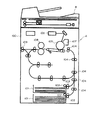
次に図5乃至図7を参照して画像読取装置について説明する。なお、図5は画像読取装置の上方斜視説明図であり、図6は画像読取装置の圧板ユニット開いた状態の上方斜視説明図である。また、図7は画像読取装置を示す主要断面説明図である。
[Image reader]
Next, the image reading apparatus will be described with reference to FIGS. 5 is an upper perspective explanatory view of the image reading device, and FIG. 6 is an upper perspective explanatory view of the image reading device in a state where the pressure plate unit is opened. FIG. 7 is a main cross-sectional explanatory view showing the image reading apparatus.
図5及び図6に示すように、圧板ユニット1の下面の静止画像読取部には静止画像原稿読取時に原稿D2をプラテンガラス6に密着するため、白地板2が取り付けられており、ヒンジ3を回転中心として圧板ユニット1が開閉できる構成になっている。
As shown in FIGS. 5 and 6, a
また、図7に示すように、搬送原稿読取部5は、略U字状の原稿搬送路(以下、「Uターンパス」という)7を有する。このUターンパス7には、原稿トレイ4に積載された原稿D1の先端位置を規制する原稿ストッパ10が設けられている。また、原稿D1を搬送する部材として、前記原稿トレイ4に積載された原稿D1の最上位のものに当接してこれをピックアップするピックアップローラ17、原稿D1を1枚ずつ分離給送する分離ローラ8及び分離パット9が設けられている。また、原稿搬送部材として、給送された原稿を読取位置へ搬送する原稿搬送手段となる搬送ローラ13、前記読取位置を通過した原稿を搬送する原稿排出手段となる排出ローラ対14が設けられている。また、原稿搬送経路には、原稿を検出するセンサとして、原稿トレイ4上の原稿D1の有無を検出する原稿有無センサ11、搬送される原稿の先端部及び後端部を検出する原稿エッジセンサ15等が取り付けられた構成となっている。
As shown in FIG. 7, the transported document reading unit 5 includes a substantially U-shaped document transport path (hereinafter referred to as “U-turn path”) 7. The U-turn path 7 is provided with a
前記原稿搬送経路における読取位置の下部には、読取位置にある原稿を読み取る読取手段となる密着型イメージセンサ16が設けられている。この密着型イメージセンサ16は、光源としてのLEDアレイから原稿D1の画像情報面に光を照射し、画像情報面で反射した反射光をレンズを介してセンサ素子に結像して画像情報を読み取るものである。
A
搬送原稿読取部5においては、操作者が原稿D1を原稿トレイ4に載置するとき、原稿D1の読取画像面を上側にして装置の手前側からセットされるようになっている。このとき、原稿D1の先端位置が原稿ストッパ10によって規制され、原稿有無センサ11により原稿D1が有ることが検知される。
In the transported document reading unit 5, when the operator places the document D1 on the
そして、操作者が不図示の操作部から読取開始を指示すると、不図示の駆動部が回転する。これにより、原稿ストッパ10が押し下げられ、ピックアップローラ17によって、原稿D1が分離ローラ8と分離パット9の分離部まで搬送され、原稿D1が1枚ずつに分離され、最上位の原稿D1が分離搬送される。また、分離された原稿D1が搬送ローラ13によって、Uターンパス7に沿って搬送され、さらに密着型イメージセンサ16の読取部へ搬送される。
When the operator instructs to start reading from an operation unit (not shown), a drive unit (not shown) rotates. As a result, the
原稿搬送部では、原稿エッジセンサ15により原稿D1の先端部が検知されると、その位置から所定量搬送されたところで、密着型イメージセンサ16による画像情報の読み取りが開始される。読取開始後、原稿は排出ローラ対14に向かう。そして、原稿エッジセンサ15により原稿D1の後端部が検知されると、その位置から所定量搬送されたところで、密着型イメージセンサ16による画像情報の読み取りを終了する。そして、当該原稿D1は、排出ローラ対14によって装置外へ排出される。
When the leading edge of the document D1 is detected by the
このようにして、搬送原稿読取部5では、原稿有無センサ11が原稿無しを検知するまで上述した読取動作を繰り返す。 In this manner, the transported document reading unit 5 repeats the above-described reading operation until the document presence / absence sensor 11 detects that there is no document.
[原稿浮き上がり防止構成]
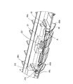
上記原稿読み取りに際し、読取位置で原稿の浮き上がりを防止するために、本実施形態では原稿押さえ手段及び原稿押圧手段が設けられている。次にそのための構成について図1乃至図3を参照して説明する。なお、図1は搬送原稿読取部の拡大説明図であり、図2は読取白地板を原稿搬送方向から見た説明図である。また、図3は原稿押圧手段の構成を示す斜視説明図である。
[Document lift prevention configuration]
In order to prevent the document from being lifted at the reading position when the document is read, document pressing means and document pressing means are provided in this embodiment. Next, a configuration for that purpose will be described with reference to FIGS. FIG. 1 is an enlarged explanatory view of the conveyed original reading unit, and FIG. 2 is an explanatory view of the read white background plate as viewed from the original conveying direction. FIG. 3 is an explanatory perspective view showing the configuration of the document pressing means.
(原稿押さえ手段)
図1に示すように、密着型イメージセンサ16の上方部には、読取位置Yにある原稿を支持するプラテンであるコンタクトガラス12が設けられており、搬送される原稿をコンタクトガラス12に密着させて読み取る。そのために、読取位置Yにある原稿をコンタクトガラス12に押さえるための押さえ手段となる読取白地板20が設けられている。この読取白地板20は下ガイド部材21に対して揺動可能に取り付けられ、付勢バネ25によってコンタクトガラス12方向に付勢されている。
(Document holding means)
As shown in FIG. 1, a
前記読取白地板20は、図2に示すように、原稿搬送方向と直交する原稿幅方向の両端はコンタクトガラス12と当接する当接部20a,20bと、コンタクトガラス12から0.3〜0.5mm程浮かせた離間部20cから構成されている。当接部20a、20bは、搬送領域外に設けられている。つまり、当接部20a、20bは、原稿が搬送される搬送領域から幅方向にずれて設けられている。原稿は離間部20cの下部を通過し、コンタクトガラス12へ押圧しないようにしている。これにより、原稿に付着したのり等の汚れがコンタクトガラス12に付着することを軽減するができ、読取画質が向上する。
As shown in FIG. 2, the reading
また、前記読取白地板20は、前述のように付勢バネ25によりコンタクトガラス12へ付勢されている。しかし、本実施形態の読取白地板20はモールド部材であるため、読取白地板20の中央部を付勢バネ25で付勢すると、中央部が撓んで、コンタクトガラス12と接触してしまう。そのため、本実施形態では前記付勢バネ25は読取白地板20の両端部を付勢するように配置している。これにより、離間部20cは搬送される原稿の浮き上がりを抑えるが、押圧することはなく、原稿付着物をコンタクトガラス12に付着させることがない。
Further, the reading
(原稿押圧手段)
また、本実施形態では図1に示すように、原稿の搬送経路における前記搬送ローラ13と読取白地板20との間に、原稿をコンタクトガラス12に押圧するための押圧手段18が設けられている。この押圧手段18は原稿先端がコンタクトガラス12の下流側に設けられた下流側ガイド部材24や排出ローラ対14に突入する時の原稿読取位置Yでの原稿ばたつきによる大きな画像乱れを抑えるものである。
(Document pressing means)
In the present embodiment, as shown in FIG. 1, a pressing means 18 for pressing the document against the
前記押圧手段18は、下ガイド部材21に揺動可能に支持されている。具体的には、図3に示すように、下ガイド部材21のボス部21aに押圧手段18のボス嵌合部18cが回動可能に取り付けられ、対向部A部も同様構成となっており、これによって押圧手段18が下ガイド部材21に対して揺動可能となっている。また、押圧手段18は付勢手段となる付勢バネ22によってコンタクトガラス12の方へ付勢されている。
The pressing means 18 is supported by the
そして、押圧手段18は、図3に示すように、原稿幅方向の複数箇所にコンタクトガラス12方向へ突出したリブ部18d,18eが形成されている。このリブ部18d,18eは、原稿をコンタクトガラス12へ案内するように湾曲した板状に構成され、このリブ部18d,18eがコンタクトガラス12に当接し、他の部分は当接しないように構成されている。
As shown in FIG. 3, the pressing means 18 is formed with
搬送ローラ13によって搬送された原稿は、押圧手段18によってコンタクトガラス12へ案内され、かつ、リブ部18d,18eによってコンタクトガラス12へ押圧される。このため、例え厚手の原稿であってもコンタクトガラス12から浮き上がることがなく、原稿のばたつきを抑え、読取位置Yでの画像乱れを軽減することが可能となる。そして、リブ部18d,18eは原稿との接触面積が小さいため、原稿との摺擦音を軽減される。
The document conveyed by the conveying
これにより、読取白地板20や押圧手段18の付勢力を大きくすることなく、原稿のばたつきを抑え、かつ、摺擦音の軽減を実現している。
As a result, the flapping of the document is suppressed and the rubbing noise is reduced without increasing the urging force of the reading
〔第2実施形態〕
次に第2実施形態に係る装置について図8乃至図11を参照して説明する。なお、本実施形態の装置の基本構成は前述した実施形態と同一であるため重複する説明は省略し、ここでは本実施形態の特徴となる構成について説明する。また、前述した実施形態と同一機能を有する部材には同一符号を付す。
[Second Embodiment]
Next, an apparatus according to a second embodiment will be described with reference to FIGS. Note that the basic configuration of the apparatus of this embodiment is the same as that of the above-described embodiment, and thus a duplicate description is omitted. Here, a configuration that is a feature of this embodiment will be described. Moreover, the same code | symbol is attached | subjected to the member which has the same function as embodiment mentioned above.
本実施形態が前述した実施形態と異なるのは、押圧手段18が原稿搬送状態に応じてコンタクトガラス12に当接、離間可能に構成されている点である。
The present embodiment is different from the above-described embodiment in that the pressing means 18 is configured to be able to contact and separate from the
そのために、図8及び図9に示すように、付勢バネ22によって付勢されてコンタクトガラス12に当接する押圧手段18をコンタクトガラス12から離間させる離間手段が設けられている。なお、図8は第2実施形態に係る押圧手段の斜視説明図であり、図9は第2実施形態に係る画像読取部の断面説明図である。
For this purpose, as shown in FIGS. 8 and 9, a separating means for separating the pressing means 18 that is urged by the urging
図8及び図9に示すように、押圧手段18は揺動規制部18a,18bが設けられており、その屈曲した先端が下ガイド部材21に係止している。そして、前記揺動規制部18a,18bの屈曲した先端と下ガイド部材21の間には離間手段となる高分子アクチュエータ19,23が取り付けられている。この高分子アクチュエータ19,23は、電圧の印加によって伸縮動作を行う特徴を有しており、本実施形態では正電圧を印加すると伸びの動作を、負電圧を印加すると縮みの動作を行う特性をもったものが用いられている。なお、アクチュエータは高分子と金属の複合体で構成したものであってもよい。
As shown in FIGS. 8 and 9, the pressing means 18 is provided with
図8及び図9は高分子アクチュエータ19,23が縮んだ状態を示している。この状態では押圧手段18は付勢バネ22によって付勢され、リブ部18d,18eがコンタクトガラス12に当接しえるような押圧位置にある。
8 and 9 show the
図10は高分子アクチュエータ19,23が伸びた状態を示す斜視説明図であり、図11はその状態の断面説明図である。図に示すように、高分子アクチュエータ19,23に正電圧を印加すると、高分子アクチュエータ19,23が伸びる。これにより、揺動規制部18a,18bが上方へ引き上げられ、リブ部18d,18eがコンタクトガラス12から離間する離間位置にある。ここで、高分子アクチュエータ19,23の伸び力は付勢バネ22の付勢力よりも強くなっており、付勢バネ22の付勢力に抗して高分子アクチュエータ19、23が離間位置へ揺動規制部18a、18bを移動させる。
FIG. 10 is a perspective explanatory view showing a state in which the
上記のように押圧手段18がコンタクトガラス12から当接、離間可能な構成において、本実施形態では、まず、搬送された原稿先端が排出ローラ対14に到達するまでは、高分子アクチュエータ19,23に負電圧を印加する。これにより、図8、図9に示すように、高分子アクチュエータ19,23が縮んでリブ部18d,18eがコンタクトガラス12に当接し、搬送される原稿を付勢バネ22の付勢力によってコンタクトガラス12に押圧する。このため、原稿先端が下流側ガイド部材24や排出ローラ14に突入する時の原稿読取位置Yでの原稿ばたつきが抑えられる。
In the configuration in which the pressing means 18 can come into contact with and separate from the
そして、搬送される原稿先端が排出ローラ対14に到達した後、原稿後端が搬送ローラ13から抜けるまでの間に高分子アクチュエータ19,23に負電圧を印加する。これにより、図10、図11に示すように、高分子アクチュエータ19,23が伸びてリブ部18d,18eがコンタクトガラス12から離間する。このため、搬送される原稿後端が押圧手段18を抜けるときの原稿にかかる負荷変動による原稿ばたつきが抑えられる。
Then, a negative voltage is applied to the
なお、前記押圧手段18が離間位置にあるときは、搬送される原稿は搬送ローラ13と排出ローラ対14に保持されているため、安定した搬送状態となっている。このため、押圧手段18がコンタクトガラス12から離間しても、原稿読取精度にはほとんど影響はない。
When the pressing means 18 is in the separated position, the document to be conveyed is held by the conveying
本実施形態にあっては、上述のように原稿のばたつきが抑えられるとともに、原稿後端が搬送ローラ13を抜けるときの負荷変動が抑えられ、読取画像全域に渡って、画像乱れのない画像読取装置の実現が可能となる。
In the present embodiment, the fluttering of the original is suppressed as described above, and the load fluctuation when the rear end of the original passes through the conveying
A …画像形成装置
B …画像読取装置
D1 …原稿
1 …圧板ユニット
2 …白地板
3 …ヒンジ
4 …原稿トレイ
5 …搬送原稿読取部
6 …プラテンガラス
7 …Uターンパス
8 …分離ローラ
9 …分離パット
10 …原稿ストッパ
11 …原稿有無センサ
12 …コンタクトガラス
13 …搬送ローラ
14 …排出ローラ対
15 …原稿エッジセンサ
16 …密着型イメージセンサ
17 …ピックアップローラ
18 …押圧手段
18a,18b …揺動規制部
18c …ボス嵌合部
18d,18e …リブ部
19,23 …高分子アクチュエータ
20 …読取白地板
20a,20b …当接部
20c …離間部
21 …下ガイド部材
21a …ボス部
22 …付勢バネ
24 …下流側ガイド部材
25 …付勢バネ
100 …装置本体
101 …シートカセット
102 …給送ローラ
103 …分離ローラ対
104 …搬送ローラ対
105 …感光体ドラム
106 …露光手段
107 …現像手段
108 …定着手段
109 …排出ローラ対
DESCRIPTION OF SYMBOLS A ... Image forming apparatus B ... Image reading apparatus D1 ... Original 1 ...
10 ... Document stopper
11… Document presence sensor
12… contact glass
13… Conveying roller
14… discharge roller pair
15… Document edge sensor
16… Contact type image sensor
17… Pickup roller
18… Pressing means
18a, 18b ... Swing restriction part
18c ... Boss fitting part
18d, 18e ... rib part
19, 23 ... Polymer actuator
20… Reading white board
20a, 20b ... contact part
20c ... separation part
21 ... Lower guide member
21a ... Boss
22… Biasing spring
24 ... Downstream guide member
25… Biasing spring
100 ... Main unit
101… sheet cassette
102 ... Feed roller
103… Separation roller pair
104… Conveying roller pair
105… Photoreceptor drum
106… Exposure means
107… Developing means
108… Fixing means
109… discharge roller pair
Claims (8)
前記読取位置にある原稿を読み取る読取手段と、
前記読取位置に原稿を搬送する原稿搬送手段と、
前記読取位置を通過した原稿を搬送する原稿排出手段と、
原稿の搬送経路における前記原稿搬送手段と前記読取位置との間の位置で、原稿を前記プラテンに押圧する、移動可能な押圧手段と、
前記押圧手段を前記プラテンに付勢するための付勢手段と、
前記読取位置において前記プラテンから原稿の浮き上がりを抑えるために前記プラテンに対向し、かつ、原稿の搬送領域内で前記プラテンから離間している押さえ手段と、
を有し、
前記押圧手段は、前記プラテンの方向に突出し、原稿の搬送方向に沿って延びたリブ部を有し、前記リブ部は、前記原稿搬送手段によって搬送されながら前記読取手段によって画像が読み取られている原稿を前記付勢手段の付勢力によって前記プラテンに押圧することを特徴とする画像読取装置。 A platen that supports the document in the reading position;
Reading means for reading a document at the reading position;
A document conveying means for conveying the document to the reading position;
A document discharge means for transporting a document that has passed through the reading position;
At a position between the reading position and the document conveying means in the conveying path of the document to press the original document on the platen, and pressing means movable,
Biasing means for biasing the pressing means against the platen;
A pressing unit that faces the platen and suppresses the platen from being lifted from the platen in the reading position, and is spaced apart from the platen in the document conveyance region;
Have
The pressing means has a rib portion that protrudes in the direction of the platen and extends in the document conveyance direction, and the rib portion reads an image by the reading device while being conveyed by the document conveyance device. An image reading apparatus, wherein an original is pressed against the platen by an urging force of the urging means.
前記読取位置にある原稿を読み取る読取手段と、
前記読取位置に原稿を搬送する原稿搬送手段と、
前記読取位置を通過した原稿を搬送する原稿排出手段と、
原稿の搬送経路における、前記原稿搬送手段と前記読取位置との間の位置で、原稿を前記プラテンに押圧する、移動可能な押圧手段と、
前記押圧手段を前記プラテンに付勢するための付勢手段と、
前記押圧手段を、前記原稿搬送手段によって搬送されながら前記読取手段によって画像が読み取られている原稿を前記プラテンに前記付勢手段の付勢力によって原稿を押圧するための押圧位置から、前記押圧位置よりも前記プラテンから離間した離間位置に移動させる離間手段と、を有し、
前記押圧手段は、搬送される原稿先端が前記原稿排出手段に到達するまでは前記押圧位置にあり、搬送される原稿先端が前記原稿排出手段に到達した後、原稿後端が前記原稿搬送手段から抜けるまでの間に、前記押圧位置から前記離間位置に前記離間手段によって移動されることを特徴とする画像読取装置。 A platen that supports the document in the reading position;
Reading means for reading a document at the reading position;
A document conveying means for conveying the document to the reading position;
A document discharge means for transporting a document that has passed through the reading position;
In the transport path of the document, at a position between the reading position and the document conveying means, presses the document to the platen, and pressing means movable,
Biasing means for biasing the pressing means against the platen;
From the pressing position, the pressing unit is configured to press the document on which the image is read by the reading unit while being conveyed by the document conveying unit from the pressing position for pressing the document by the urging force of the urging unit. And a separation means for moving to a separation position separated from the platen,
The pressing means is in the pressing position until the leading edge of the conveyed document reaches the document discharging means, and after the leading edge of the conveyed document reaches the document discharging means, the trailing edge of the document is separated from the document conveying means. The image reading apparatus is moved from the pressing position to the separation position by the separation means until it comes off.
画像情報に基づいて、シートに画像を形成する画像形成手段と、
を備えたことを特徴とする画像形成装置。 An image reading apparatus according to any one of claims 1 to 7,
Image forming means for forming an image on a sheet based on image information;
An image forming apparatus comprising:
Priority Applications (3)
| Application Number | Priority Date | Filing Date | Title |
|---|---|---|---|
| JP2007090561A JP4854563B2 (en) | 2007-03-30 | 2007-03-30 | Image reading apparatus and image forming apparatus |
| US12/054,972 US7755815B2 (en) | 2007-03-30 | 2008-03-25 | Image reading apparatus and image formation apparatus |
| CN2008100874471A CN101276172B (en) | 2007-03-30 | 2008-03-28 | Image reading apparatus |
Applications Claiming Priority (1)
| Application Number | Priority Date | Filing Date | Title |
|---|---|---|---|
| JP2007090561A JP4854563B2 (en) | 2007-03-30 | 2007-03-30 | Image reading apparatus and image forming apparatus |
Publications (3)
| Publication Number | Publication Date |
|---|---|
| JP2008252470A JP2008252470A (en) | 2008-10-16 |
| JP2008252470A5 JP2008252470A5 (en) | 2010-05-06 |
| JP4854563B2 true JP4854563B2 (en) | 2012-01-18 |
Family
ID=39793804
Family Applications (1)
| Application Number | Title | Priority Date | Filing Date |
|---|---|---|---|
| JP2007090561A Active JP4854563B2 (en) | 2007-03-30 | 2007-03-30 | Image reading apparatus and image forming apparatus |
Country Status (3)
| Country | Link |
|---|---|
| US (1) | US7755815B2 (en) |
| JP (1) | JP4854563B2 (en) |
| CN (1) | CN101276172B (en) |
Families Citing this family (9)
| Publication number | Priority date | Publication date | Assignee | Title |
|---|---|---|---|---|
| US7692828B2 (en) * | 2005-05-10 | 2010-04-06 | Canon Kabushiki Kaisha | Image reading apparatus |
| JP4815964B2 (en) * | 2005-09-16 | 2011-11-16 | ブラザー工業株式会社 | Image reading device |
| TWI332478B (en) * | 2007-05-25 | 2010-11-01 | Primax Electronics Ltd | Automatic document feeder with a detachable sheet-pressing slice |
| TWI318929B (en) * | 2007-06-08 | 2010-01-01 | Primax Electronics Ltd | Automatically document feeding scanner with a movable guiding rib device |
| JP5000427B2 (en) * | 2007-08-21 | 2012-08-15 | 京セラドキュメントソリューションズ株式会社 | Automatic document feeder and image forming apparatus |
| US8854706B2 (en) * | 2009-07-07 | 2014-10-07 | Kabushiki Kaisha Toshiba | Auto document feeding device |
| JP5825549B2 (en) * | 2011-06-08 | 2015-12-02 | 株式会社リコー | Sheet conveying apparatus, image reading apparatus, and image forming apparatus |
| JP6155942B2 (en) * | 2013-07-31 | 2017-07-05 | ブラザー工業株式会社 | Image reading device |
| WO2016039733A1 (en) | 2014-09-09 | 2016-03-17 | Intel Corporation | Multi-gate high electron mobility transistors and methods of fabrication |
Family Cites Families (13)
| Publication number | Priority date | Publication date | Assignee | Title |
|---|---|---|---|---|
| JPH11289428A (en) * | 1998-04-03 | 1999-10-19 | Canon Inc | Image reader and image processor |
| JP2001007979A (en) * | 1999-06-25 | 2001-01-12 | Sharp Corp | Document reader |
| US7079294B1 (en) * | 1999-10-29 | 2006-07-18 | Canon Kabushiki Kaisha | Image reading apparatus and image forming apparatus |
| JP2002232642A (en) * | 2001-01-30 | 2002-08-16 | Canon Aptex Inc | Original feeder and image forming device provided with this feeder |
| JP2003051916A (en) * | 2001-08-06 | 2003-02-21 | Canon Inc | Document feeder and image reader |
| JP2003051915A (en) * | 2001-08-06 | 2003-02-21 | Canon Inc | Image reader and imaging device provided with the same |
| JP2003060849A (en) * | 2001-08-20 | 2003-02-28 | Ricoh Co Ltd | Automatic original reader and image forming device |
| JP3951718B2 (en) * | 2002-01-22 | 2007-08-01 | 村田機械株式会社 | Paper feeder |
| JP2003289422A (en) * | 2002-01-24 | 2003-10-10 | Ricoh Co Ltd | Image scanner |
| JP3626943B2 (en) | 2002-06-24 | 2005-03-09 | ニスカ株式会社 | Automatic document feeder |
| JP2004140474A (en) | 2002-10-15 | 2004-05-13 | Canon Inc | Image reading apparatus |
| US7692828B2 (en) | 2005-05-10 | 2010-04-06 | Canon Kabushiki Kaisha | Image reading apparatus |
| JP4810299B2 (en) * | 2005-05-10 | 2011-11-09 | キヤノン株式会社 | Image reading device |
-
2007
- 2007-03-30 JP JP2007090561A patent/JP4854563B2/en active Active
-
2008
- 2008-03-25 US US12/054,972 patent/US7755815B2/en active Active
- 2008-03-28 CN CN2008100874471A patent/CN101276172B/en active Active
Also Published As
| Publication number | Publication date |
|---|---|
| JP2008252470A (en) | 2008-10-16 |
| US7755815B2 (en) | 2010-07-13 |
| US20080239415A1 (en) | 2008-10-02 |
| CN101276172A (en) | 2008-10-01 |
| CN101276172B (en) | 2010-07-21 |
Similar Documents
| Publication | Publication Date | Title |
|---|---|---|
| JP4854563B2 (en) | Image reading apparatus and image forming apparatus | |
| JP4176100B2 (en) | Image forming apparatus | |
| JP5562145B2 (en) | Document reader | |
| JP5130166B2 (en) | Document holding device and image forming apparatus equipped with the same | |
| US11247860B2 (en) | Sheet conveying apparatus, image reading apparatus, and image forming apparatus | |
| WO2010137410A1 (en) | Sheet discharge device and image forming device | |
| JP2020007061A (en) | Paper feeder, and image forming apparatus provided with the same | |
| JP2018125616A (en) | Image reading device and image forming apparatus | |
| US20060256402A1 (en) | Image reading apparatus | |
| JP4970196B2 (en) | Image reading apparatus and image forming apparatus | |
| JP2007131403A (en) | Sheet aligning device and image forming device | |
| JP2009256054A (en) | Conveyed sheet detecting device and sheet conveying device | |
| JP6571976B2 (en) | Sheet feeding apparatus, image reading apparatus, and image forming apparatus | |
| US8243343B2 (en) | Recording material detecting apparatus | |
| JP4665401B2 (en) | Printing result inspection apparatus and image forming apparatus | |
| JP2003051915A (en) | Image reader and imaging device provided with the same | |
| JP4513885B2 (en) | Paper feeder | |
| JP3347656B2 (en) | Sheet transport device | |
| JP6291783B2 (en) | Document conveying apparatus and image forming apparatus | |
| US20230257220A1 (en) | Feeding device and image forming apparatus incorporating same | |
| JP3654396B2 (en) | Recording medium transport device | |
| JP6579437B2 (en) | Document conveying apparatus and image forming apparatus | |
| JP2002152463A (en) | Automatic original carrying device and picture reading device | |
| JP3317680B2 (en) | Document feeder | |
| JP3981756B2 (en) | Paper discharge device |
Legal Events
| Date | Code | Title | Description |
|---|---|---|---|
| A521 | Request for written amendment filed |
Free format text: JAPANESE INTERMEDIATE CODE: A523 Effective date: 20100323 |
|
| A621 | Written request for application examination |
Free format text: JAPANESE INTERMEDIATE CODE: A621 Effective date: 20100323 |
|
| A977 | Report on retrieval |
Free format text: JAPANESE INTERMEDIATE CODE: A971007 Effective date: 20110719 |
|
| A131 | Notification of reasons for refusal |
Free format text: JAPANESE INTERMEDIATE CODE: A131 Effective date: 20110726 |
|
| A521 | Request for written amendment filed |
Free format text: JAPANESE INTERMEDIATE CODE: A523 Effective date: 20110922 |
|
| TRDD | Decision of grant or rejection written | ||
| A01 | Written decision to grant a patent or to grant a registration (utility model) |
Free format text: JAPANESE INTERMEDIATE CODE: A01 Effective date: 20111018 |
|
| A01 | Written decision to grant a patent or to grant a registration (utility model) |
Free format text: JAPANESE INTERMEDIATE CODE: A01 |
|
| A61 | First payment of annual fees (during grant procedure) |
Free format text: JAPANESE INTERMEDIATE CODE: A61 Effective date: 20111025 |
|
| FPAY | Renewal fee payment (event date is renewal date of database) |
Free format text: PAYMENT UNTIL: 20141104 Year of fee payment: 3 |
|
| R151 | Written notification of patent or utility model registration |
Ref document number: 4854563 Country of ref document: JP Free format text: JAPANESE INTERMEDIATE CODE: R151 |
|
| FPAY | Renewal fee payment (event date is renewal date of database) |
Free format text: PAYMENT UNTIL: 20141104 Year of fee payment: 3 |