CN101275481A - Discharge purifying device - Google Patents
Discharge purifying device Download PDFInfo
- Publication number
- CN101275481A CN101275481A CNA2008100810874A CN200810081087A CN101275481A CN 101275481 A CN101275481 A CN 101275481A CN A2008100810874 A CNA2008100810874 A CN A2008100810874A CN 200810081087 A CN200810081087 A CN 200810081087A CN 101275481 A CN101275481 A CN 101275481A
- Authority
- CN
- China
- Prior art keywords
- mentioned
- oxidation catalyst
- exhaust
- exhaust gas
- flow path
- Prior art date
- Legal status (The legal status is an assumption and is not a legal conclusion. Google has not performed a legal analysis and makes no representation as to the accuracy of the status listed.)
- Pending
Links
Images


Classifications
-
- F—MECHANICAL ENGINEERING; LIGHTING; HEATING; WEAPONS; BLASTING
- F01—MACHINES OR ENGINES IN GENERAL; ENGINE PLANTS IN GENERAL; STEAM ENGINES
- F01N—GAS-FLOW SILENCERS OR EXHAUST APPARATUS FOR MACHINES OR ENGINES IN GENERAL; GAS-FLOW SILENCERS OR EXHAUST APPARATUS FOR INTERNAL COMBUSTION ENGINES
- F01N3/00—Exhaust or silencing apparatus having means for purifying, rendering innocuous, or otherwise treating exhaust
- F01N3/08—Exhaust or silencing apparatus having means for purifying, rendering innocuous, or otherwise treating exhaust for rendering innocuous
- F01N3/10—Exhaust or silencing apparatus having means for purifying, rendering innocuous, or otherwise treating exhaust for rendering innocuous by thermal or catalytic conversion of noxious components of exhaust
- F01N3/18—Exhaust or silencing apparatus having means for purifying, rendering innocuous, or otherwise treating exhaust for rendering innocuous by thermal or catalytic conversion of noxious components of exhaust characterised by methods of operation; Control
- F01N3/20—Exhaust or silencing apparatus having means for purifying, rendering innocuous, or otherwise treating exhaust for rendering innocuous by thermal or catalytic conversion of noxious components of exhaust characterised by methods of operation; Control specially adapted for catalytic conversion ; Methods of operation or control of catalytic converters
- F01N3/2053—By-passing catalytic reactors, e.g. to prevent overheating
-
- F—MECHANICAL ENGINEERING; LIGHTING; HEATING; WEAPONS; BLASTING
- F01—MACHINES OR ENGINES IN GENERAL; ENGINE PLANTS IN GENERAL; STEAM ENGINES
- F01N—GAS-FLOW SILENCERS OR EXHAUST APPARATUS FOR MACHINES OR ENGINES IN GENERAL; GAS-FLOW SILENCERS OR EXHAUST APPARATUS FOR INTERNAL COMBUSTION ENGINES
- F01N13/00—Exhaust or silencing apparatus characterised by constructional features ; Exhaust or silencing apparatus, or parts thereof, having pertinent characteristics not provided for in, or of interest apart from, groups F01N1/00 - F01N5/00, F01N9/00, F01N11/00
- F01N13/009—Exhaust or silencing apparatus characterised by constructional features ; Exhaust or silencing apparatus, or parts thereof, having pertinent characteristics not provided for in, or of interest apart from, groups F01N1/00 - F01N5/00, F01N9/00, F01N11/00 having two or more separate purifying devices arranged in series
-
- F—MECHANICAL ENGINEERING; LIGHTING; HEATING; WEAPONS; BLASTING
- F01—MACHINES OR ENGINES IN GENERAL; ENGINE PLANTS IN GENERAL; STEAM ENGINES
- F01N—GAS-FLOW SILENCERS OR EXHAUST APPARATUS FOR MACHINES OR ENGINES IN GENERAL; GAS-FLOW SILENCERS OR EXHAUST APPARATUS FOR INTERNAL COMBUSTION ENGINES
- F01N3/00—Exhaust or silencing apparatus having means for purifying, rendering innocuous, or otherwise treating exhaust
- F01N3/08—Exhaust or silencing apparatus having means for purifying, rendering innocuous, or otherwise treating exhaust for rendering innocuous
- F01N3/10—Exhaust or silencing apparatus having means for purifying, rendering innocuous, or otherwise treating exhaust for rendering innocuous by thermal or catalytic conversion of noxious components of exhaust
- F01N3/105—General auxiliary catalysts, e.g. upstream or downstream of the main catalyst
- F01N3/106—Auxiliary oxidation catalysts
-
- F—MECHANICAL ENGINEERING; LIGHTING; HEATING; WEAPONS; BLASTING
- F01—MACHINES OR ENGINES IN GENERAL; ENGINE PLANTS IN GENERAL; STEAM ENGINES
- F01N—GAS-FLOW SILENCERS OR EXHAUST APPARATUS FOR MACHINES OR ENGINES IN GENERAL; GAS-FLOW SILENCERS OR EXHAUST APPARATUS FOR INTERNAL COMBUSTION ENGINES
- F01N3/00—Exhaust or silencing apparatus having means for purifying, rendering innocuous, or otherwise treating exhaust
- F01N3/08—Exhaust or silencing apparatus having means for purifying, rendering innocuous, or otherwise treating exhaust for rendering innocuous
- F01N3/10—Exhaust or silencing apparatus having means for purifying, rendering innocuous, or otherwise treating exhaust for rendering innocuous by thermal or catalytic conversion of noxious components of exhaust
- F01N3/18—Exhaust or silencing apparatus having means for purifying, rendering innocuous, or otherwise treating exhaust for rendering innocuous by thermal or catalytic conversion of noxious components of exhaust characterised by methods of operation; Control
- F01N3/20—Exhaust or silencing apparatus having means for purifying, rendering innocuous, or otherwise treating exhaust for rendering innocuous by thermal or catalytic conversion of noxious components of exhaust characterised by methods of operation; Control specially adapted for catalytic conversion ; Methods of operation or control of catalytic converters
- F01N3/2006—Periodically heating or cooling catalytic reactors, e.g. at cold starting or overheating
- F01N3/2033—Periodically heating or cooling catalytic reactors, e.g. at cold starting or overheating using a fuel burner or introducing fuel into exhaust duct
-
- F—MECHANICAL ENGINEERING; LIGHTING; HEATING; WEAPONS; BLASTING
- F01—MACHINES OR ENGINES IN GENERAL; ENGINE PLANTS IN GENERAL; STEAM ENGINES
- F01N—GAS-FLOW SILENCERS OR EXHAUST APPARATUS FOR MACHINES OR ENGINES IN GENERAL; GAS-FLOW SILENCERS OR EXHAUST APPARATUS FOR INTERNAL COMBUSTION ENGINES
- F01N3/00—Exhaust or silencing apparatus having means for purifying, rendering innocuous, or otherwise treating exhaust
- F01N3/08—Exhaust or silencing apparatus having means for purifying, rendering innocuous, or otherwise treating exhaust for rendering innocuous
- F01N3/10—Exhaust or silencing apparatus having means for purifying, rendering innocuous, or otherwise treating exhaust for rendering innocuous by thermal or catalytic conversion of noxious components of exhaust
- F01N3/24—Exhaust or silencing apparatus having means for purifying, rendering innocuous, or otherwise treating exhaust for rendering innocuous by thermal or catalytic conversion of noxious components of exhaust characterised by constructional aspects of converting apparatus
- F01N3/28—Construction of catalytic reactors
- F01N3/2803—Construction of catalytic reactors characterised by structure, by material or by manufacturing of catalyst support
-
- F—MECHANICAL ENGINEERING; LIGHTING; HEATING; WEAPONS; BLASTING
- F01—MACHINES OR ENGINES IN GENERAL; ENGINE PLANTS IN GENERAL; STEAM ENGINES
- F01N—GAS-FLOW SILENCERS OR EXHAUST APPARATUS FOR MACHINES OR ENGINES IN GENERAL; GAS-FLOW SILENCERS OR EXHAUST APPARATUS FOR INTERNAL COMBUSTION ENGINES
- F01N2240/00—Combination or association of two or more different exhaust treating devices, or of at least one such device with an auxiliary device, not covered by indexing codes F01N2230/00 or F01N2250/00, one of the devices being
- F01N2240/28—Combination or association of two or more different exhaust treating devices, or of at least one such device with an auxiliary device, not covered by indexing codes F01N2230/00 or F01N2250/00, one of the devices being a plasma reactor
-
- F—MECHANICAL ENGINEERING; LIGHTING; HEATING; WEAPONS; BLASTING
- F01—MACHINES OR ENGINES IN GENERAL; ENGINE PLANTS IN GENERAL; STEAM ENGINES
- F01N—GAS-FLOW SILENCERS OR EXHAUST APPARATUS FOR MACHINES OR ENGINES IN GENERAL; GAS-FLOW SILENCERS OR EXHAUST APPARATUS FOR INTERNAL COMBUSTION ENGINES
- F01N2570/00—Exhaust treating apparatus eliminating, absorbing or adsorbing specific elements or compounds
- F01N2570/14—Nitrogen oxides
-
- Y—GENERAL TAGGING OF NEW TECHNOLOGICAL DEVELOPMENTS; GENERAL TAGGING OF CROSS-SECTIONAL TECHNOLOGIES SPANNING OVER SEVERAL SECTIONS OF THE IPC; TECHNICAL SUBJECTS COVERED BY FORMER USPC CROSS-REFERENCE ART COLLECTIONS [XRACs] AND DIGESTS
- Y02—TECHNOLOGIES OR APPLICATIONS FOR MITIGATION OR ADAPTATION AGAINST CLIMATE CHANGE
- Y02A—TECHNOLOGIES FOR ADAPTATION TO CLIMATE CHANGE
- Y02A50/00—TECHNOLOGIES FOR ADAPTATION TO CLIMATE CHANGE in human health protection, e.g. against extreme weather
- Y02A50/20—Air quality improvement or preservation, e.g. vehicle emission control or emission reduction by using catalytic converters
-
- Y—GENERAL TAGGING OF NEW TECHNOLOGICAL DEVELOPMENTS; GENERAL TAGGING OF CROSS-SECTIONAL TECHNOLOGIES SPANNING OVER SEVERAL SECTIONS OF THE IPC; TECHNICAL SUBJECTS COVERED BY FORMER USPC CROSS-REFERENCE ART COLLECTIONS [XRACs] AND DIGESTS
- Y02—TECHNOLOGIES OR APPLICATIONS FOR MITIGATION OR ADAPTATION AGAINST CLIMATE CHANGE
- Y02T—CLIMATE CHANGE MITIGATION TECHNOLOGIES RELATED TO TRANSPORTATION
- Y02T10/00—Road transport of goods or passengers
- Y02T10/10—Internal combustion engine [ICE] based vehicles
- Y02T10/12—Improving ICE efficiencies
Landscapes
- Engineering & Computer Science (AREA)
- Chemical & Material Sciences (AREA)
- Chemical Kinetics & Catalysis (AREA)
- Combustion & Propulsion (AREA)
- Mechanical Engineering (AREA)
- General Engineering & Computer Science (AREA)
- Health & Medical Sciences (AREA)
- Toxicology (AREA)
- Materials Engineering (AREA)
- Exhaust Gas After Treatment (AREA)
- Exhaust Gas Treatment By Means Of Catalyst (AREA)
Abstract
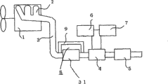
An exhaust gas purification apparatus can efficiently purify an exhaust gas even when hydrocarbon contained in the exhaust gas is excessive with content of hydrocarbon and NOx being substantially different. The apparatus has an oxidation catalyst unit ( 8 ), a plasma processing unit ( 4 ) and a NOx purification catalyst unit ( 5 ) arranged on an exhaust gas flow passage, through which the exhaust gas discharged from an engine ( 1 ) flows, in this order form an upstream side to a downstream side. The oxidation catalyst unit ( 8 ) is provided with a main flow passage ( 31 ) through which the exhaust gas flows while being in contact with an oxidation catalyst, and a bypass flow passage ( 9 ) through which the exhaust gas flows without contacting the oxidation catalyst.
Description
Technical field
The present invention relates to the Exhaust gas purifying device that the harmful components of handle from the exhaust that motor is discharged are purified.
Background technique
The exhaust of discharging, contain nitrogen oxide (NOx), carbon monoxide (CO), hydrocarbon (HC) as harmful components from motor car engine.
As the existing apparatus that purifies these harmful gases, residual oxygen (O in the exhaust
2) in the stoichiometry opinion burning of denier, three-way catalyst is practicability.By the exhaust from motor is fed this three-way catalyst, the harmful gas composition is converted into H
2O, CO
2, N
2Deng clean air.
In contrast, in the exhaust of lean combustion (lean-burn) motor or diesel engine, contain a lot of oxygen, so adopt three-way catalyst to be difficult to purify NOx.
Wish a kind of Exhaust gas purifying device that is difficult to adopt the gasoline lean combustion engine of three-way catalyst or the harmful components reduction that diesel engine is discharged that makes, plasma treatment portion is installed in engine exhaust pipe, the existing people of automobile exhaust treatment device who connects NOx cleaning catalyst portion in the downstream side of this plasma processing division proposes (for example, referring to patent documentation 1).
At this plasma processing division, have sparking electrode, form structure between this sparking electrode by exhaust.This exhaust is handled by discharge plasma, and oxygen molecule and water molecule in the exhaust at first dissociate by following formula:
O
2→2O
*
H
2O→H
*+OH
*
This O
*With OH
*With harmful gas hydrocarbon (HC) and nitrous oxide (NO) reaction, finally generate formaldehyde or acetaldehyde, nitrogen dioxide (NO
2), carbon dioxide (CO
2) and water (H
2O):
HC+O
*(or OH
*) → aldehyde, CO
2, H
2O
NO+O
*→NO
2
The aldehyde that produces by this discharge chemistry reaction is reducibility gas, NO
2Be oxidizing gas.As this reducibility gas and oxidizing gas NO by next stage
xDuring cleaning catalyst portion,, generate nitrogen (N in catalyst surface reducibility gas and oxidizing gas reaction
2), carbon dioxide (CO
2) and water (H
2O) be cleaned.
Aldehyde+NO
2→ N
2, CO
2, H
2O
Therefore, carry out the discharge plasma processing, for reactive high reducibility gas and oxidizing gas, make it pass through NOx cleaning catalyst portion then the activation of the harmful gas in the exhaust, make exhaust gas purification containing the oxygen exhaust.
In addition, other examples (for example, referring to patent documentation 2) that also have plasma in the exhaust activation, to use.
In this example,, utilize discharge to generate the strong NO of oxidizing force for making the filter regeneration that captures the particle (PM) in the exhaust
2And ozone (O
3) etc.
To contain this NO
2And O
3Gas as regeneration gas, supply with the PM filter.NO
2And O
3Deng oxidizing gas the soot particulates of PM filter traps is carried out oxidation, be transformed into CO
2Thereby, regeneration filter.
In the patent documentation 2,, a plurality of PM filters are set, use alternate with each other for the PM filter does not capture and regenerate simultaneously.The PM structure of filter is that when regeneration PM filter, from the exhaust flow path disconnection, the part of exhaust is supplied with the PM structure of filter by plasma discharge reactor having (plasmadischarge reactor).
Patent documentation 1: the spy opens flat 6-335621 communique
Patent documentation 2: the spy opens the 2006-29132 communique
Summary of the invention
Yet when petrol engine moved under the lean combustion condition, the content surplus of the relative NOx of HC that contains in the exhaust adopted the exhaust gas treatment device with above-mentioned plasma treatment portion and NOx cleaning catalyst portion, the O that discharge plasma generates
*With OH
*Most of and the HC reaction Deng free radicals, so and the free radicals deficiency of NOx reaction, the NO among the NOx can not activate and be NO
2
When being such exhaust gas composition, as the NO of the high oxidizing gas of reactivity
2Deficiency, the discharge plasma treatment effeciency reduces, and causes the essential excessive discharging energy that drops into.
Therefore, depend on the method for operation of motor, the HC in the exhaust is significantly different sometimes with the ratio of NOx, at this moment, has the problem of essential excessive discharging energy.
As the reduction method of the excessive HC that contains in the exhaust, can consider oxidation catalyst to be set at the leading portion of discharge plasma.
But, when oxidation catalyst is set, oxygen content is many in the exhaust of lean combustion condition, HC and this oxygen react under the oxidation catalyst effect becomes zero, so in the exhaust only the residual exhaust of NOx supply with plasma treatment portion, in plasma treatment portion, do not generate the aldehyde of reducibility gas, this NOx takes place in the problem that next section NOx cleaning catalyst portion can not be cleaned.
In patent documentation 2, although divide the part of exhaust, supply with plasma discharge reactor having, the HC in the exhaust of telling is identical with the ratio of NOx, and the using plasma discharge reactor exists and above-mentioned same problem points.
The present invention is to address the above problem a little as problem, and purpose is to provide a kind of exhaust gas treatment device, though the HC surplus that in exhaust, contains, HC and NOx ratio significantly simultaneously can efficient yet purifying exhaust gas well.
The Exhaust gas purifying device that the present invention relates to, on the exhaust flow path of the exhaust air flow that motor is discharged, oxidation catalyst portion, plasma treatment portion and NOx cleaning catalyst portion are set from the upstream, and above-mentioned oxidation catalyst portion has: primary flow path that above-mentioned exhaust contacts with oxidation catalyst, flows and above-mentioned exhaust and the mobile non-contiguously by-pass flow road of above-mentioned oxidation catalyst.
In addition, the Exhaust gas purifying device that the present invention relates to, on the exhaust flow path of the exhaust air flow of discharging from motor, oxidation catalyst portion, plasma treatment portion and NOx cleaning catalyst portion are set from the upstream, have the hydrocarbon supplier that above-mentioned exhaust flow path between above-mentioned oxidation catalyst portion and above-mentioned plasma treatment portion is supplied with hydrocarbon.
According to the Exhaust gas purifying device that the present invention relates to, though the HC surplus that contains in the exhaust, HC and NOx ratio significantly simultaneously can efficient yet purifying exhaust gas well.
Description of drawings
Fig. 1 is the schematic representation of the basic comprising of exhaust gas treatment device in the expression embodiment of the present invention 1.
Fig. 2 is a part of sectional stereogram of plasma treatment portion shown in Figure 1.
Fig. 3 (a) is the stereogram of oxidation catalyst portion shown in Figure 1, (b), (c) be respectively the stereogram of the improvement example of oxidation catalyst portion.
Fig. 4 is the schematic representation of the basic comprising of exhaust gas treatment device in the expression embodiment of the present invention 2.
Fig. 5 is the stereogram of the improvement example on by-pass flow road shown in Figure 4.
Fig. 6 is the schematic representation of the basic comprising of exhaust gas treatment device in the expression embodiment of the present invention 3.
Fig. 7 is the schematic representation of the basic comprising of exhaust gas treatment device in the expression embodiment of the present invention 4.
Fig. 8 is the schematic representation of the basic comprising of exhaust gas treatment device in the expression embodiment of the present invention 5.
Fig. 9 is the measurement result figure that the formaldehyde growing amount compares with propylene and propane.
[explanation of symbol]
1 motor, 4 plasma treatment portions, 5 NOx cleaning catalyst portions, 8 oxidation catalyst portions, 9 by-pass flow roads, 10 flow control devices, 11 fuel baths, 12 fuel supplying devices (hydrocarbon supplier), 13 unsaturated hydrocarbon supplieies, 31 primary flow path.
Embodiment
Fig. 1 is the schematic representation of basic comprising of the exhaust gas treatment device of expression embodiment 1.
Have a plurality of cylinders (not shown) in the inside of motor 1, the exhaust of cylinder interior burning by many gas exhaust manifolds 2, an outlet pipe 3, drains into the outside.
In this exhaust gas treatment device, on the outlet pipe 3 that forms exhaust flow path, set gradually oxidation catalyst portion 8, plasma treatment portion 4 and NOx cleaning catalyst portion 5 from the upstream.
Fig. 2 is a part of section three-dimensional map of representing plasma treatment portion 4 particularly.
In the inside of outer tube 21, with the fixing high-field electrodes 22 of reticulated work 23 be arranged on outer tube 21 coaxial on.For to high-field electrode 22 service voltages, high-field electrode terminal 22a and power supply terminal 22b connect by high voltage cable 26.This power supply terminal 22b is connected by cable (not shown) with plasma control apparatus 6.On outer tube 21,, 21 of ground electrode 24 and outer tubes are contacted installation by the screw 27 that is fixedly clamped.In addition, by the screw 27 that is fixedly clamped, the cable (not shown) that is connected with plasma control apparatus 6 also is mounted.
Also have, the material of reticulated work 23 for example can adopt potteries such as aluminium oxide so long as insulator gets final product.In addition, the material of high-field electrode 22 and ground electrode 24 for example, can adopt stainless steel so long as electric conductor gets final product.
In the plasma treatment portion 4 that constitutes like this, by apply ac high voltage or pulse high-voltage between high-field electrode 22 and ground electrode 24, the space between high-field electrode 22 and outer tube 21 produces silent discharge.Produce the airflow direction length in the space of silent discharge, identical with the blast air of ground electrode 24 to length.That is, in the space that fences up by ground electrode 24, produce silent discharge.Import the exhaust in this plasma processing division 4, by reticulated work 23, in the silent discharge space.Exhaust is carried out chemical reaction by discharge plasma at this in by process.
In the primary flow path 31 of oxidation catalyst portion 8, on the original cellular ceramic honey comb base material that uses, load as the precious metal of oxidation catalyst, for example platinum (Pt) or palladium (Pd).
By-pass flow road 9 is shown in Fig. 3 (a), at any catalyzer of not load of central part of oxidation catalyst portion 8 and form.
Also have, by-pass flow road 9 shown in Fig. 3 (b), by making not load of the peripheral part oxidation catalyst of oxidation catalyst portion 8, also can have by-pass flow road 9 at the peripheral part of oxidation catalyst portion 8.At this moment, the primary flow path 31 that exhaust contacts with oxidation catalyst in oxidation catalyst portion 8 forms the radially inner side on by-pass flow road 9.
In addition, shown in Fig. 3 (c),, also can form by-pass flow road 9 at the random position of oxidation catalyst portion 8 inside by making not load of the random position oxidation catalyst of oxidation catalyst portion 8.At this moment, the primary flow path 31 of oxidation catalyst portion 8 is to remove zone in addition, by-pass flow road 9.
The proportions of ingredients regulating device is made of primary flow path 31 and by-pass flow road 9.The proportions of ingredients regulating device is adjusted to specified value to hydrocarbon in the exhaust of supplying with plasma treatment portion 4 and the proportions of ingredients of NOx.
NOx cleaning catalyst portion 5 is also same with above-mentioned oxidation catalyst, on cellular ceramic honey comb base material load catalyzer, can adopt silver catalyst or zeolites catalyzer etc., it loads in the ceramic base material purification of aldehyde and NOx is reacted on the effective aluminium oxide.
In the Exhaust gas purifying device of above-mentioned formation, the exhaust by gas exhaust manifold 2 compiles imports oxidation catalyst portion 8 by outlet pipe 3.In the exhaust that imports, the gas that flows through primary flow path 31 contacts with oxidation catalyst, stands oxidation processes.Here said so-called oxidation processes means the HC that contains in the exhaust, CO is converted into CO
2With H
2O.In addition, a part of NO among the NOx also is converted into NO
2
In the exhaust that imports,, do not change and directly pass through by the gas on by-pass flow road 9.Respectively by primary flow path 31 exhaust with by-pass flow road 9, plasma treatment portion 4 is supplied with at interflow and being mixed, and stands conversion treatment.
Here said so-called conversion treatment, at least a portion that means the hydrocarbon that contains in the exhaust mainly is converted into aldehydes, and NO is converted into NO
2Then, contain aldehyde and the NO that obtains by conversion
2Exhaust, deliver to NOx cleaning catalyst portion 5, carry out purified treatment.
Here said so-called purified treatment means the aldehyde and the NO that contain in the exhaust
2Be converted into N
2, CO
2, H
2O, and all the other a part of HC and CO are converted into CO
2And H
2O.
But, except that HC or NOx etc., contain the O about several %~10% in the exhaust
2In the lean combustion engine that gasoline is used, when adopting the Exhaust gas purifying device of the present embodiment because oxygen concentration height in the exhaust, by primary flow path 31, with compositions such as HC in the exhaust that oxidation catalyst contacts and CO, by with O
2Catalytic reaction, almost all complete oxidations are CO
2With H
2O.
Therefore, by primary flow path 31, the HC vanishing that contacts with oxidation catalyst, and arrive outlet with original concentration by the HC on by-pass flow road 9.In addition, adopt oxidation catalyst, though the part of NO is transformed into NO
2, but be almost original certain value as all concentration of NOx.Any conversion does not take place in the NOx by by-pass flow road 9, directly arrives outlet.
The exhaust of flowing through primary flow path 31 and the ratio that flows through the exhaust on by-pass flow road 9, the inlet in oxidation catalyst portion 8, when the velocity flow profile of exhaust is even, respectively by inlet area than decision.The setting of this inlet area ratio, the concentration that depends on the HC that contains in the exhaust and NOx is when as the HC of purpose and the concentration ratio of NOx.
For example, the C1 conversion concentration of the HC in the exhaust is that 3000ppmC, NOx concentration are 100ppm, and when the ratio as the HC/NOx of purpose was 1.0, the area of oxidation catalyst was preferably 29: 1 with the ratio of the area on by-pass flow road 9.
When reach such primary flow path 31 and by-pass flow road 9 areas than the time, the HC concentration in outlet port is that 100ppmC (=C1 conversion concentration), NOx concentration reach 100ppm.
As the ratio of the HC/NOx of purpose, how many kinds of the aldehyde that produces because of plasma treatment portion 4 changes.When producing formaldehyde HCHO, because following reaction takes place in plasma treatment portion 4:
2HCHO+2NO
2→N
2+2CO
2+2H
2O
The ratio of formaldehyde and NOx, promptly the ratio of HC/NOx reaches 2/2=1.0.When producing acetaldehyde CH
3During CHO, because following reaction takes place:
4CH
3CHO+10NO
2→5N
2+8CO
2+8H
2O
The ratio of acetaldehyde and NOx, promptly the ratio of HC/NOx reaches 4 * 2/10=0.8.
Therefore, when setting the area on by-pass flow road 9,, decide by the aldehyde formation characteristic of plasma treatment portion 4 as the HC/NOx ratio of purpose.
Being mixed, when it is supplied with plasma treatment portion 4, by the O of plasma generation by the gas of primary flow path 31 with by-pass flow road 9
*Or OH
*Almost have an effect equably Deng free radicals and HC and NOx, generate aldehyde and NO respectively from it
2So, can effectively utilize.
The aldehyde and the NO that effectively generate in plasma treatment portion 4
2, be cleaned processing in NOx cleaning catalyst portion 5.
As mentioned above, as adopt the Exhaust gas purifying device of this embodiment, the area ratio of crossing by the blast air that changes primary flow path 31 and by-pass flow road 9, HC in the exhaust and the NOx concentration ratio that can achieve the goal, so the energy efficient that plasma treatment portion 4 can lack is converted into aldehyde to HC, and NO is converted into NO
2
And the NOx cleaning catalyst portion 5 follow-up can purify for NO
2Purification reaches the aldehyde-containing gas of optium concentration.
In addition, oxidation catalyst portion 8 is because primary flow path 31 is integrated with 9 formation of by-pass flow road, so do not need the parts that append of by-pass flow road 9 usefulness.
Fig. 4 is the schematic representation of basic comprising of the exhaust gas treatment device of expression embodiment 2.
In this embodiment, the exhaust flow path that is formed by outlet pipe 3 has: load the by-pass flow road 9 of primary flow path 31 and not load oxidation catalyst of oxidation catalyst.
Other formations are identical with embodiment 1.
In this embodiment, form the pipe arrangement on by-pass flow road 9, constitute by the metal catheter similar with outlet pipe 3.
The caliber on by-pass flow road 9 is by decisions such as the concentration ratio of HC that contains in the above-mentioned exhaust and NOx and purpose concentration ratios.
Here, load the primary flow path 31 of oxidation catalyst be cellular structure, and by-pass flow road 9 is guide-tube structures, considers numerical aperture except that both diameters, the caliber on decision by-pass flow road 9 makes the ratio of the HC/NOx that achieves the goal.
Specifically, when primary flow path 31 was the ceramic honeycomb body of diameter 100mm cylindraceous, cell density (celldensity) 400cpsi (unit number per square inch), numerical aperture was about 85%, and the useful area that blast air is crossed is about 6700mm
2When the ratio of purpose HC/NOx reaches 1.0, load the ratio of useful area and the area on by-pass flow road 9 of primary flow path 31 of oxidation catalyst preferably reach 29: 1, the catheter diameter on the by-pass flow road 9 of this moment is about 17mm.In fact, consider that it is necessary that aeration resistances such as the length on length, by-pass flow road 9 of primary flow path 31 and tortuosity are finely tuned.
Also have, as shown in Figure 5, also can have the gap by the peripheral part that makes cellular primary flow path 31 and form by-pass flow road 9.
Therefore, form the gap, can make primary flow path 31 and by-pass flow road 9 integrated by circumferencial direction along the inner circumference wall of outlet pipe 3.
As adopt the Exhaust gas purifying device of this embodiment, and same by the primary flow path 31 and the by-pass flow road 9 of oxidation catalyst that respectively load be set with embodiment 1, HC in the exhaust and the NOx concentration ratio that can achieve the goal.
In addition, compare with embodiment 1, though part count increases, by-pass flow road 9 can directly utilize metal catheter, is immersed in the manufacturing procedure that forms bypass in the catalyst solution after the mask of sealing inlet and outlet usefulness can be installed.
Fig. 6 is the schematic representation of basic comprising of the exhaust gas treatment device of expression embodiment 3.
In this embodiment, in the by-pass flow road 9 of embodiment 2, flow control device 10 is set.
Other constitute with embodiment 2 same.
In embodiment 1,2, according to HC and the NOx concentration of investigation in advance in the operating conditions of motor 1, the decision load size on primary flow path 31 and by-pass flow road 9 of oxidation catalyst, the proportioning of setting exhaust.
Opposite with it, in this embodiment,,, can change bypass flow according to the operating conditions of motor 1 by the control of flow control device 10, enlarge the operating conditions scope of motor 1.
For example, when the air fuel ratio of motor 1 is 20, the methane conversion concentration of HC (C1 conversion concentration) is 3000ppm, NOx concentration is 100ppm, and when air fuel ratio was 18, HC concentration was 2500ppm, NOx concentration is 500ppm, the extraction flow that flows through by-pass flow road 9 increases, and the ratio on oxidation catalyst and by-pass flow road 9 is when fading to 4: 1, and purpose HC/NOx adjustable ratio saves to 1.0.
HC and NOx concentration according to the air fuel ratio of motor 1, are remembered measured load in flow control device 10 in advance, or the sensor (not shown) that detects HC or NOx etc. are arranged on outlet pipe 3 midway, adjust flow control device 10 according to its signal and also can.
As Exhaust gas purifying device according to this embodiment, adopt flow control device 10, can change the extraction flow on by-pass flow road 9, so when the change in concentration of HC emissions or NOx, also can transfer to the purpose value to the ratio of HC/NOx.
Fig. 7 is the schematic representation of basic comprising of the engine device of the exhaust gas treatment device of expression with embodiment 4.
In this embodiment, replace the by-pass flow road 9 of embodiment 1~3, on the exhaust flow path between oxidation catalyst portion 8 and the plasma treatment portion 4, connect the fuel supplying device 12 of handle from the hydrocarbon supplier of fuel such as fuel bath 11 supply gasoline.
Other constitute with embodiment 1 same.
In this embodiment, from the exhaust of motor 1, all by oxidation catalyst portion 8, HC is oxidized to CO
2And H
2O, the part of NO is oxidized to NO among the NOx
2From the fuel supplying device 12 in its downstream, the fuel that contains an amount of HC that coincide with NOx concentration is supplied with from fuel bath 11.The fuel of supplying with, petrolic occasion is a gasoline, is the hydrocarbon of carbon number about 8.The fuel of supplying with, promptly HC measures, if shown in enforcement scheme 1,2, the operation condition of motor 1 has determined, supplies a certain amount of getting final product.In addition, shown in enforcement scheme 3, when the operation condition of motor 1 changes, supply with the HC amount corresponding and get final product with it.
When liquid fuels such as supply gasoline, when spraying devices such as fuel supplying device 12 use spargers, can promote the mixing in exhaust.
According to the Exhaust gas purifying device of this embodiment, the HC in the exhaust removes with oxidation catalyst, and the HC corresponding with NOx concentration supplies with from the outside, thus supply with exhaust in the corresponding HC of NOx concentration, the ratio of HC/HOx can reach suitable value.
In addition, owing to supply with in the exhaust, as HC with fuel so do not need new HC groove etc. sending out the machine machine.
Fig. 8 is the schematic representation of basic comprising of the engine device of the exhaust gas treatment device of expression with embodiment 5.
In this embodiment, on the exhaust flow path between oxidation catalyst portion 8 and the plasma treatment portion 4, be connected unsaturated hydrocarbon supplier 13.
The proportions of ingredients regulating device is a hydrocarbon supplier 13.
Other constitute with embodiment 4 same.
In this embodiment, from the exhaust of motor 1, all by oxidation catalyst portion 8, HC is oxidized to CO
2And H
2O, the part of NO is oxidized to NO among the NOx
2, this point and embodiment 4 are same.
In its downstream, supply with an amount of unsaturated hydrocarbon corresponding with NOx concentration from unsaturated hydrocarbon supplier 13.The HC amount of supplying with, shown in enforcement scheme 1 and 2, if the operation condition of motor 1 determined, supplies with a certain amount of getting final product, shown in enforcement scheme 3, when the operation condition of change motor 1, supply with the HC corresponding and measure and get final product with it.
After Fig. 9 illustrates the inventor sneak into unsaturated hydrocarbon propylene and saturated hydrocarbon propane with same concentration in air, the determination experiment result of the formaldehyde that plasma treatment portion generates.
Transverse axis is represented 1 liter of discharging energy that gas applies to flowing through.
As can be seen from Figure 9, propylene is compared with propane under the same conditions, and the aldehyde of generation is many.
Therefore,,, when adopting the unsaturated hydrocarbon propylene, compare during with employing saturated hydrocarbon propane, can effectively change into reactive high aldehyde with less discharging energy as the kind of supplying with HC emissions in plasma treatment portion 4.
As Exhaust gas purifying device according to this embodiment, HC emissions is removed in oxidation catalyst portion 8, the unsaturated hydrocarbon corresponding with NOx concentration supplied with from the outside, so the ratio of the HC/NOx in the exhaust of supply plasma treatment portion 4 can reach suitable value, simultaneously, in plasma treatment portion 4, can effectively change into reactive high reducibility gas and oxidizing gas.
Also have, Exhaust gas purifying device of the present invention is not limited to purify the harmful components from the exhaust that gasoline is discharged with lean combustion engine, and diesel engine also can adopt.
In addition, except that automobile, for example also applicable to purifying the poisonous exhaust composition of discharging from engine of boat and ship.
Claims (8)
1. an Exhaust gas purifying device is characterized in that, on the exhaust flow path of the exhaust air flow that motor is discharged, oxidation catalyst portion, plasma treatment portion and NOx cleaning catalyst portion is set from the upstream; This device has: the proportions of ingredients regulating device that the proportions of ingredients of hydrocarbon in the above-mentioned exhaust of the above-mentioned plasma treatment of supply portion and NOx is adjusted to specified value.
2. according to the Exhaust gas purifying device described in the claim 1, it is characterized in that above-mentioned oxidation catalyst portion has: primary flow path that above-mentioned exhaust contacts with oxidation catalyst, flows and above-mentioned exhaust and the mobile non-contiguously by-pass flow road of above-mentioned oxidation catalyst; Above-mentioned proportions of ingredients regulating device is made of above-mentioned primary flow path and above-mentioned by-pass flow road.
3. according to the Exhaust gas purifying device described in the claim 2, it is characterized in that, the above-mentioned exhaust flow path that above-mentioned oxidation catalyst portion is provided with, by inside be divided into load the part of above-mentioned oxidation catalyst constitute with the pipe arrangement of the part of the above-mentioned oxidation catalyst of load not, load the part of above-mentioned oxidation catalyst be above-mentioned primary flow path, and the part of the above-mentioned oxidation catalyst of load is not above-mentioned by-pass flow road.
4. according to the Exhaust gas purifying device described in the claim 2, it is characterized in that, the above-mentioned exhaust flow path that above-mentioned oxidation catalyst portion is provided with, by load the stream of above-mentioned oxidation catalyst constitute with the stream of the above-mentioned oxidation catalyst of load not, load the stream of above-mentioned oxidation catalyst be above-mentioned primary flow path, and the stream of the above-mentioned oxidation catalyst of load is not above-mentioned by-pass flow road.
5. according to the Exhaust gas purifying device described in the claim 4, it is characterized in that, the flow control device of the above-mentioned extraction flow of control is set on above-mentioned by-pass flow road.
6. according to the Exhaust gas purifying device described in the claim 1, it is characterized in that above-mentioned proportions of ingredients regulating device is arranged between above-mentioned oxidation catalyst portion and the above-mentioned plasma treatment portion, supply with the hydrocarbon supplier of hydrocarbon to above-mentioned exhaust flow path.
7. according to the Exhaust gas purifying device described in the claim 6, it is characterized in that above-mentioned hydrocarbon is a power fuel.
8. according to the Exhaust gas purifying device described in the claim 6, it is characterized in that above-mentioned hydrocarbon is a unsaturated hydrocarbon.
Applications Claiming Priority (2)
| Application Number | Priority Date | Filing Date | Title |
|---|---|---|---|
| JP2007085299A JP2008240698A (en) | 2007-03-28 | 2007-03-28 | Exhaust emission control device |
| JP2007-085299 | 2007-03-28 |
Publications (1)
| Publication Number | Publication Date |
|---|---|
| CN101275481A true CN101275481A (en) | 2008-10-01 |
Family
ID=39719750
Family Applications (1)
| Application Number | Title | Priority Date | Filing Date |
|---|---|---|---|
| CNA2008100810874A Pending CN101275481A (en) | 2007-03-28 | 2008-02-26 | Discharge purifying device |
Country Status (4)
| Country | Link |
|---|---|
| US (1) | US20080241006A1 (en) |
| JP (1) | JP2008240698A (en) |
| CN (1) | CN101275481A (en) |
| DE (1) | DE102008015722A1 (en) |
Cited By (3)
| Publication number | Priority date | Publication date | Assignee | Title |
|---|---|---|---|---|
| CN101784772B (en) * | 2007-09-21 | 2012-02-08 | 丰田自动车株式会社 | Exhaust purification device for internal combustion engine |
| CN104519982A (en) * | 2012-08-09 | 2015-04-15 | 埃克森美孚研究工程公司 | Catalytic reduction of NOx with high activity catalysts with acetaldehyde reductant |
| CN106050485A (en) * | 2016-08-04 | 2016-10-26 | 广西玉柴机器股份有限公司 | Plasma system of natural gas engine |
Families Citing this family (6)
| Publication number | Priority date | Publication date | Assignee | Title |
|---|---|---|---|---|
| JP2012214364A (en) * | 2011-03-28 | 2012-11-08 | Ngk Insulators Ltd | HONEYCOMB STRUCTURE, Si-SiC BASED COMPOSITE MATERIAL, METHOD FOR MANUFACTURING HONEYCOMB STRUCTURE, AND METHOD FOR MANUFACTURING Si-SiC BASED COMPOSITE MATERIAL |
| US8815195B2 (en) | 2012-08-09 | 2014-08-26 | Exxonmobil Research And Engineering Company | Catalytic reduction of NOx with high activity catalysts with propylene reductant |
| US8834823B2 (en) | 2012-08-09 | 2014-09-16 | Exxonmobil Research And Engineering Company | Catalytic reduction of NOx with high activity catalysts |
| US10107213B2 (en) * | 2016-12-01 | 2018-10-23 | Ford Global Technologies, Llc | Method and system for exhaust gas recirculation and heat recovery |
| CN108261896A (en) * | 2018-02-06 | 2018-07-10 | 山东盛唐环保科技有限公司 | A kind of purification method of low-temperature plasma exhaust gas |
| RU2689020C1 (en) * | 2018-10-30 | 2019-05-23 | Радченко Виталий Анатольевич | Device for the internal combustion engines emissions cleaning of the nitrogen oxides using the non-equilibrium low-temperature plasma and the absorber |
Family Cites Families (4)
| Publication number | Priority date | Publication date | Assignee | Title |
|---|---|---|---|---|
| JPH06335621A (en) | 1993-05-28 | 1994-12-06 | Aqueous Res:Kk | Exhaust gas treating device for automobile |
| JP3237611B2 (en) * | 1997-11-11 | 2001-12-10 | トヨタ自動車株式会社 | Exhaust gas purification device for internal combustion engine |
| EP1632654A1 (en) * | 2003-05-22 | 2006-03-08 | Hino Motors, Ltd. | Exhaust gas purifier |
| JP2006029132A (en) | 2004-07-13 | 2006-02-02 | Toyota Motor Corp | Exhaust emission control device |
-
2007
- 2007-03-28 JP JP2007085299A patent/JP2008240698A/en active Pending
-
2008
- 2008-01-25 US US12/020,065 patent/US20080241006A1/en not_active Abandoned
- 2008-02-26 CN CNA2008100810874A patent/CN101275481A/en active Pending
- 2008-03-26 DE DE102008015722A patent/DE102008015722A1/en not_active Withdrawn
Cited By (3)
| Publication number | Priority date | Publication date | Assignee | Title |
|---|---|---|---|---|
| CN101784772B (en) * | 2007-09-21 | 2012-02-08 | 丰田自动车株式会社 | Exhaust purification device for internal combustion engine |
| CN104519982A (en) * | 2012-08-09 | 2015-04-15 | 埃克森美孚研究工程公司 | Catalytic reduction of NOx with high activity catalysts with acetaldehyde reductant |
| CN106050485A (en) * | 2016-08-04 | 2016-10-26 | 广西玉柴机器股份有限公司 | Plasma system of natural gas engine |
Also Published As
| Publication number | Publication date |
|---|---|
| US20080241006A1 (en) | 2008-10-02 |
| JP2008240698A (en) | 2008-10-09 |
| DE102008015722A1 (en) | 2008-10-02 |
Similar Documents
| Publication | Publication Date | Title |
|---|---|---|
| CN101275481A (en) | Discharge purifying device | |
| CN101564646B (en) | Method for purification of an exhaust gas from a diesel engine | |
| US7380395B2 (en) | Exhaust gas system | |
| US6247303B1 (en) | Method and device for removing oxidic noxious substances in an oxygen-containing exhaust gas and engine which is operated therewith | |
| US6475350B2 (en) | Method for removing NOx and other pollutants from gas streams using a plasma assisted catalyst | |
| CN1865671B (en) | Exhaust gas purifying apparatus and method thereof | |
| CN101305169B (en) | Exhaust purifying system for internal combustion engine | |
| US20160356200A1 (en) | Exhaust gas post treatment device | |
| CN103089380A (en) | Electronically heated nox adsorber catalyst | |
| CN102400749A (en) | Exhaust gas aftertreatement system and method of operation | |
| US11377993B2 (en) | Exhaust gas purification system for a gasoline engine | |
| WO2006036311A2 (en) | PLASMA-ASSISTED NOx REDUCTION | |
| US11859526B2 (en) | Exhaust gas purification system for a gasoline engine | |
| US11547969B2 (en) | Exhaust gas purification system for a gasoline engine | |
| US8899020B2 (en) | Apparatus and method for assisting selective catalytic reduction | |
| KR20110025133A (en) | Exhaust gas purification apparatus | |
| KR101546332B1 (en) | Process for reducing no2 from combustion system exhaust | |
| JP4529822B2 (en) | Exhaust gas purification device for internal combustion engine | |
| EP1999346B1 (en) | Device for purification of exhaust gas | |
| US8544257B2 (en) | Electrically stimulated catalytic converter apparatus, and method of using same | |
| WO2018130841A1 (en) | CONTROL OF SOOT AND NOx | |
| CN217614012U (en) | NO x -CO-purification system | |
| KR20180096089A (en) | Device for reducing nitrogen oxide of diesel engine |
Legal Events
| Date | Code | Title | Description |
|---|---|---|---|
| C06 | Publication | ||
| PB01 | Publication | ||
| C10 | Entry into substantive examination | ||
| SE01 | Entry into force of request for substantive examination | ||
| C02 | Deemed withdrawal of patent application after publication (patent law 2001) | ||
| WD01 | Invention patent application deemed withdrawn after publication |
Open date: 20081001 |