CN101239552B - Method for correcting relative position of mechanism in laser engraving machine - Google Patents
Method for correcting relative position of mechanism in laser engraving machine Download PDFInfo
- Publication number
- CN101239552B CN101239552B CN 200710002865 CN200710002865A CN101239552B CN 101239552 B CN101239552 B CN 101239552B CN 200710002865 CN200710002865 CN 200710002865 CN 200710002865 A CN200710002865 A CN 200710002865A CN 101239552 B CN101239552 B CN 101239552B
- Authority
- CN
- China
- Prior art keywords
- output device
- laser engraving
- engraving machine
- point
- center point
- Prior art date
- Legal status (The legal status is an assumption and is not a legal conclusion. Google has not performed a legal analysis and makes no representation as to the accuracy of the status listed.)
- Expired - Fee Related
Links
Landscapes
- Manufacture Or Reproduction Of Printing Formes (AREA)
Abstract
一种校正雷射雕刻机中机构相对位置之方法,主要系令雷射雕刻机之输出装置于任一非加工对象上形成一标记点,且令该输出装置定位该标记点之中心点,并予以记录,再令雷射雕刻机之摄像感测装置(CCD)移动至上述标记点,且寻找该标记点之中心点,然后记录输出装置因摄像感测装置移动后,输出装置所在之位置点,最后计算输出装置记录之中心点与输出装置被移动后所在之位置点间的距离,而取得出该摄像感测装置与输出装置间正确之距离。
A method for calibrating the relative position of a mechanism in a laser engraving machine mainly comprises the following steps: causing an output device of the laser engraving machine to form a mark point on any non-processing object, and causing the output device to locate the center point of the mark point and record it, then causing a camera sensor device (CCD) of the laser engraving machine to move to the mark point and find the center point of the mark point, then recording the position point of the output device after the camera sensor device moves, and finally calculating the distance between the center point recorded by the output device and the position point of the output device after the output device is moved, thereby obtaining the correct distance between the camera sensor device and the output device.
Description
技术领域 technical field
本发明涉及一种校正激光雕刻机中机构相对位置的方法,尤指一种利用激光雕刻机的摄像感测装置(CCD)与输出装置间的结构位置设置的相依性,透过该摄像感测装置与输出装置间的位移关系与定位关系,而有效且准确取得两者间的距离,以校正激光雕刻机中摄像感测装置与输出装置的机构误差的方法,适用于激光雕刻机出厂前的校正、或使用者端第一次进行雕刻前的应用。The invention relates to a method for correcting the relative position of a mechanism in a laser engraving machine, in particular to a method for utilizing the dependency of the structure position setting between the camera sensor device (CCD) and the output device of the laser engraving machine, through the camera sensor The displacement relationship and positioning relationship between the device and the output device, and effectively and accurately obtain the distance between the two to correct the mechanism error of the camera sensing device and the output device in the laser engraving machine, which is suitable for the laser engraving machine before leaving the factory Calibration, or application before engraving for the first time on the user side.
背景技术 Background technique
使用激光雕刻的过程非常简单,如同使用计算机和打印机在纸张上打印一样,祇要编辑好各种图案,即可透过计算机将图案“打印”到雕刻机中。唯一不同之处的是,打印是将墨粉涂到纸张上,而激光雕刻是将激光输出到木制品、压克力、塑料板、金属板或石材等加工物品上,以完成雕刻的程序。The process of using laser engraving is very simple, just like using a computer and printer to print on paper, as long as the various patterns are edited, the pattern can be "printed" into the engraving machine through the computer. The only difference is that printing is the application of toner to paper, while laser engraving is the process of outputting laser light onto processed items such as wood, acrylic, plastic sheet, metal sheet or stone to complete the engraving.
现今激光雕刻机的结构设计上,激光输出装置与摄像感测装置(CCD)是结合于同一架体上,使得该输出装置与摄像感测装置可形成相对同步位移,然而,在进行雕刻过程前,由于机构在组装上会有工差的问题,加上搬运或使用上震动、晃动的缘故,使得输出装置与摄像感测装置必须透过调整,以提高输出装置切割时的精准度。习用的方式是利用打印机打印出一个基准点后,再观测实际切割误差,以填补校正值至计算机进行校正,惟此以人工方式进行校正的手续繁琐,且校正后输出装置切割时的精准度并非如预期般的准确。In the structural design of today's laser engraving machines, the laser output device and the camera sensor device (CCD) are combined on the same frame, so that the output device and the camera sensor device can form a relative synchronous displacement. However, before the engraving process , due to the problem of poor workmanship in the assembly of the mechanism, and the vibration and shaking during transportation or use, the output device and the camera sensing device must be adjusted to improve the cutting accuracy of the output device. The usual method is to use the printer to print out a reference point, and then observe the actual cutting error to fill in the correction value and send it to the computer for correction. However, the manual correction procedure is cumbersome, and the cutting accuracy of the output device after correction is not high. Accurate as expected.
发明内容 Contents of the invention
本发明的主要目的是在提供一种使用方便、快速且可有效且准确取得摄像感测装置与输出装置间的距离,以校正激光雕刻机中机构相对位置的方法。The main purpose of the present invention is to provide a method that is easy to use, fast, and can effectively and accurately obtain the distance between the camera sensing device and the output device to correct the relative position of the mechanism in the laser engraving machine.
为达上述的目的,本发明所设的一种校正激光雕刻机中机构相对位置的方法,主要是令激光雕刻机的输出装置于任一非加工对象上形成一标记点,且令该输出装置定位该标记点的中心点,并予以记录,再令激光雕刻机的摄像感测装置(CCD)移动至上述标记点,且寻找该标记点的中心点,然后记录输出装置因摄像感测装置移动后,输出装置所在的位置点,最后计算原输出装置记录的中心点与输出装置被移动后所在的位置点间的距离,而取得出该摄像感测装置与输出装置间正确的距离。In order to achieve the above-mentioned purpose, a method for correcting the relative position of the mechanism in the laser engraving machine provided by the present invention is mainly to make the output device of the laser engraving machine form a marking point on any non-processing object, and make the output device Locate the center point of the marking point and record it, then move the camera sensor device (CCD) of the laser engraving machine to the above mark point, and find the center point of the mark point, and then record the output device because the camera sensor device moves Finally, the position of the output device is calculated, and finally the distance between the center point recorded by the original output device and the moved position of the output device is calculated to obtain the correct distance between the camera sensing device and the output device.
为便于对本发明能有更深入的了解,兹藉一实施例详述于后:For the convenience of a deeper understanding of the present invention, hereby describe in detail the following by an embodiment:
附图说明 Description of drawings
图1是为本发明校正激光雕刻机中机构相对位置的方法步骤示意图。Fig. 1 is a schematic diagram of the steps of the method for correcting the relative positions of the mechanisms in the laser engraving machine according to the present invention.
附图标号说明:Explanation of reference numbers:
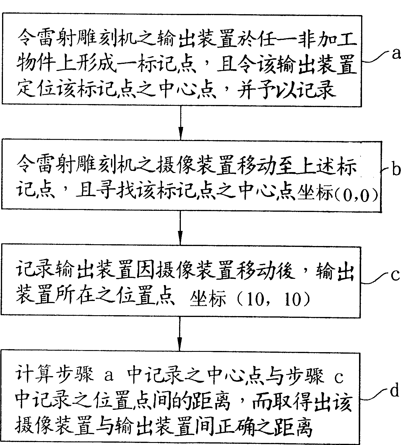
步骤a:令激光雕刻机的输出装置于任一非加工对象上形成一标记点,且令该输出装置定位该标记点的中心点,并予以记录;Step a: Make the output device of the laser engraving machine form a marking point on any non-processing object, and make the output device locate the center point of the marking point, and record it;
步骤b:令激光雕刻机的摄像感测装置(CCD)移动至上述标记点,且寻找该标记点的中心点坐标(0,0);Step b: Make the camera sensor device (CCD) of the laser engraving machine move to the above-mentioned marking point, and find the center point coordinates (0, 0) of the marking point;
步骤c:记录输出装置因摄像感测装置移动后,输出装置所在的位置点坐标(10,10);Step c: record the coordinates (10, 10) of the position of the output device after the output device moves due to the camera sensing device;
步骤d:计算步骤a中记录的中心点与步骤c中记录的位置点间的距离,而取得出该摄像感测装置与输出装置间正确的距离。Step d: Calculate the distance between the center point recorded in step a and the location point recorded in step c, so as to obtain the correct distance between the camera sensing device and the output device.
具体实施方式 Detailed ways
请参阅图1,附图内容为本发明校正激光雕刻机中机构相对位置的方法的一实施例流程图,其包括以下步骤:Please refer to Fig. 1, the accompanying drawing is a flowchart of an embodiment of the method for correcting the relative position of the mechanism in the laser engraving machine according to the present invention, which includes the following steps:
a.令激光雕刻机的输出装置于任一非加工对象上形成一标记点,且令该输出装置定位该标记点的中心点,并予以记录;a. Let the output device of the laser engraving machine form a marking point on any non-processing object, and make the output device locate the center point of the marking point and record it;
b.令激光雕刻机的摄像感测装置(CCD)移动至上述标记点,且寻找该标记点的中心点;b. Make the camera sensor device (CCD) of the laser engraving machine move to the above-mentioned marking point, and find the center point of the marking point;
c.记录输出装置因摄像感测装置移动后,输出装置所在的位置点;以及c. Record the position of the output device after the camera sensor device moves; and
d.计算步骤a中记录的中心点与步骤c中记录的位置点间的距离,而取得出该摄像感测装置与输出装置间正确的距离。d. Calculate the distance between the center point recorded in step a and the position point recorded in step c, so as to obtain the correct distance between the camera sensing device and the output device.
其中,中心点与位置点的记录与距离计算,是透过激光雕刻机内建的中央处理单元来进行处理。Among them, the recording and distance calculation of the center point and position point are processed through the built-in central processing unit of the laser engraving machine.
因此,当激光雕刻机出厂前的校正、或使用者端第一次进行雕刻前,使用者可先令激光雕刻机的输出装置移动在非加工对象上,且于该非加工对象上输出一个标记点,且透过激光雕刻机的中央处理单元而令该输出装置移动定位该标记点的中心点,并予以记录该中心点的位置(如坐标(0,0)),然后同样的再驱动激光雕刻机的摄像感测装置移动至上述标记点,且透过激光雕刻机的中央处理单元寻找该标记点的中心点(即坐标(0,0)),而由于输出装置与摄像感测装置是结合于同一架体上,使得该输出装置与摄像感测装置可形成相对同步位移,故输出装置因前述摄像感测装置移动的关系,输出装置同样的也会移动至某一位置上(如坐标(10,10)),并同时记录输出装置所在的位置点,最后,透过中央处理单元即可计算出输出装置记录的中心点(0,0)与输出装置被移动后所在的位置点(10,10)间的距离,而取得出该摄像感测装置与输出装置间正确的距离。Therefore, when the laser engraving machine is calibrated before leaving the factory, or the user end performs engraving for the first time, the user can first move the output device of the laser engraving machine on the non-processing object, and output a mark on the non-processing object point, and through the central processing unit of the laser engraving machine, the output device is moved to locate the center point of the mark point, and the position of the center point (such as coordinates (0, 0)) is recorded, and then the laser is driven in the same way The camera sensing device of the engraving machine moves to the above-mentioned marking point, and finds the center point of the marking point (that is, coordinates (0, 0)) through the central processing unit of the laser engraving machine, and since the output device and the camera sensing device are Combined on the same frame, the output device and the camera sensing device can form a relative synchronous displacement, so the output device will also move to a certain position due to the movement of the aforementioned camera sensor device (such as coordinates (10, 10)), and record the position of the output device at the same time, finally, the center point (0, 0) recorded by the output device and the position of the output device after being moved can be calculated through the central processing unit ( 10, 10) to obtain the correct distance between the camera sensing device and the output device.
藉此,当在进行雕刻前,不论摄像感测装置或输出装置在组装、操作或是运送上所产生的机构工差,可透过本发明上述的方式,利用激光雕刻机的摄像感测装置与输出装置间的结构位置设置的相依性,透过该摄像感测装置与输出装置间的位移关系与定位关系,而有效且准确取得两者间的距离,提高输出装置切割时的精准度。In this way, before engraving, regardless of the mechanism error caused by the assembly, operation or transportation of the imaging sensing device or the output device, the imaging sensing device of the laser engraving machine can be used through the above-mentioned method of the present invention The dependence on the structural position setting between the output device, through the displacement relationship and positioning relationship between the camera sensing device and the output device, can effectively and accurately obtain the distance between the two, and improve the cutting accuracy of the output device.
以上所述,仅用以揭示本发明可实施的态样,不能用以限定本发明的范围,凡熟悉本领域普通一般技术人员很明显可作变化与修饰,皆应视为不悖离本发明的实质内容。The above description is only used to reveal the practicable aspect of the present invention, and cannot be used to limit the scope of the present invention. Those who are familiar with ordinary skill in the art can obviously make changes and modifications, and all should be regarded as not departing from the present invention. the substance of the content.
Claims (2)
Priority Applications (1)
| Application Number | Priority Date | Filing Date | Title |
|---|---|---|---|
| CN 200710002865 CN101239552B (en) | 2007-02-08 | 2007-02-08 | Method for correcting relative position of mechanism in laser engraving machine |
Applications Claiming Priority (1)
| Application Number | Priority Date | Filing Date | Title |
|---|---|---|---|
| CN 200710002865 CN101239552B (en) | 2007-02-08 | 2007-02-08 | Method for correcting relative position of mechanism in laser engraving machine |
Publications (2)
| Publication Number | Publication Date |
|---|---|
| CN101239552A CN101239552A (en) | 2008-08-13 |
| CN101239552B true CN101239552B (en) | 2012-07-04 |
Family
ID=39931503
Family Applications (1)
| Application Number | Title | Priority Date | Filing Date |
|---|---|---|---|
| CN 200710002865 Expired - Fee Related CN101239552B (en) | 2007-02-08 | 2007-02-08 | Method for correcting relative position of mechanism in laser engraving machine |
Country Status (1)
| Country | Link |
|---|---|
| CN (1) | CN101239552B (en) |
Families Citing this family (4)
| Publication number | Priority date | Publication date | Assignee | Title |
|---|---|---|---|---|
| CN103204027A (en) * | 2012-01-11 | 2013-07-17 | 淮南师范学院 | Novel positioning method for drill bit of carving machine |
| CN104275975A (en) * | 2013-07-03 | 2015-01-14 | 深圳市久久犇机械设备有限公司 | OGS glass carving technique |
| CN114101917A (en) * | 2020-08-26 | 2022-03-01 | 复盛应用科技股份有限公司 | Laser engraving method |
| CN116930181B (en) * | 2023-08-21 | 2025-10-21 | 北京海洋海泰科技有限公司 | Exfoliated Cell Detection Instrument |
Citations (5)
| Publication number | Priority date | Publication date | Assignee | Title |
|---|---|---|---|---|
| CN2252978Y (en) * | 1996-04-01 | 1997-04-23 | 李长宏 | Automatic calibration device for supersonic measuring |
| CN1295905A (en) * | 1999-11-12 | 2001-05-23 | 中国科学院长春光学精密机械研究所 | Method and device for real time correcting optical element surface shape and waviness error |
| CN1356530A (en) * | 2001-10-15 | 2002-07-03 | 天津大学 | In-situ calibration device for large-size 3D space measurement and its measuring method |
| CN1667362A (en) * | 2004-03-08 | 2005-09-14 | 发那科株式会社 | Measuring system |
| CN1831468A (en) * | 2005-03-10 | 2006-09-13 | 新奥博为技术有限公司 | Method for deciding relative position of laser scanner and robot |
-
2007
- 2007-02-08 CN CN 200710002865 patent/CN101239552B/en not_active Expired - Fee Related
Patent Citations (5)
| Publication number | Priority date | Publication date | Assignee | Title |
|---|---|---|---|---|
| CN2252978Y (en) * | 1996-04-01 | 1997-04-23 | 李长宏 | Automatic calibration device for supersonic measuring |
| CN1295905A (en) * | 1999-11-12 | 2001-05-23 | 中国科学院长春光学精密机械研究所 | Method and device for real time correcting optical element surface shape and waviness error |
| CN1356530A (en) * | 2001-10-15 | 2002-07-03 | 天津大学 | In-situ calibration device for large-size 3D space measurement and its measuring method |
| CN1667362A (en) * | 2004-03-08 | 2005-09-14 | 发那科株式会社 | Measuring system |
| CN1831468A (en) * | 2005-03-10 | 2006-09-13 | 新奥博为技术有限公司 | Method for deciding relative position of laser scanner and robot |
Also Published As
| Publication number | Publication date |
|---|---|
| CN101239552A (en) | 2008-08-13 |
Similar Documents
| Publication | Publication Date | Title |
|---|---|---|
| EP2765458A3 (en) | Movable body drive method, movable body drive system, pattern formation method, pattern forming apparatus, exposure method, exposure apparatus, and device manufacturing method | |
| JP6058465B2 (en) | Printing apparatus and printing method | |
| CN101239552B (en) | Method for correcting relative position of mechanism in laser engraving machine | |
| JP2005108194A5 (en) | ||
| CN106289062B (en) | A kind of bearing calibration of benchmark camera offset | |
| JP5323631B2 (en) | Inkjet image recording apparatus and belt conveyance correction method | |
| JP6221753B2 (en) | Marking apparatus and marking method | |
| JP2013111775A5 (en) | ||
| CN109685744A (en) | A kind of scanning galvanometer accuracy correcting method | |
| CN108955535B (en) | Solder paste printer calibration and alignment method | |
| CN106705860A (en) | Laser distance measurement method | |
| JP5311973B2 (en) | Printer | |
| JP2011079257A5 (en) | ||
| JP2011151548A (en) | Method for calibrating flat bed scanner | |
| JP2004114357A (en) | Adjustment of print position in print control device | |
| TW200704146A (en) | Plotting method, plotting device, plotting system and correction method | |
| JP3974445B2 (en) | Mark recognition method and apparatus | |
| CN114383510B (en) | Optical sensing system and optical navigation system | |
| JP2016034725A (en) | Label printer and method of controlling label printer | |
| CN110682005B (en) | A real-time correction method and control device for laser marking | |
| CN112810137A (en) | Scanning galvanometer correction method and system for laser powder bed melting equipment | |
| CN101332707A (en) | Ink jet device and method for correcting ink jet | |
| US7623941B2 (en) | Method for adjusting the relative position of device of laser engraver | |
| CN116766691B (en) | A positioning slotting method and system | |
| JP2009166389A5 (en) |
Legal Events
| Date | Code | Title | Description |
|---|---|---|---|
| C06 | Publication | ||
| PB01 | Publication | ||
| C10 | Entry into substantive examination | ||
| SE01 | Entry into force of request for substantive examination | ||
| C14 | Grant of patent or utility model | ||
| GR01 | Patent grant | ||
| CF01 | Termination of patent right due to non-payment of annual fee | ||
| CF01 | Termination of patent right due to non-payment of annual fee |
Granted publication date: 20120704 |