CN101200220B - Systems and methods for passively directing aircraft engine nozzle flows - Google Patents
Systems and methods for passively directing aircraft engine nozzle flows Download PDFInfo
- Publication number
- CN101200220B CN101200220B CN2007103068896A CN200710306889A CN101200220B CN 101200220 B CN101200220 B CN 101200220B CN 2007103068896 A CN2007103068896 A CN 2007103068896A CN 200710306889 A CN200710306889 A CN 200710306889A CN 101200220 B CN101200220 B CN 101200220B
- Authority
- CN
- China
- Prior art keywords
- flow path
- nozzle
- outlet
- engine
- path wall
- Prior art date
- Legal status (The legal status is an assumption and is not a legal conclusion. Google has not performed a legal analysis and makes no representation as to the accuracy of the status listed.)
- Expired - Fee Related
Links
- 238000000034 method Methods 0.000 title claims abstract description 23
- 239000003570 air Substances 0.000 claims abstract description 19
- 239000012080 ambient air Substances 0.000 claims abstract description 12
- 230000002093 peripheral effect Effects 0.000 claims description 16
- 238000011144 upstream manufacturing Methods 0.000 claims description 9
- 239000012530 fluid Substances 0.000 claims description 6
- 238000004088 simulation Methods 0.000 claims description 3
- 230000007613 environmental effect Effects 0.000 claims description 2
- 230000000694 effects Effects 0.000 description 12
- 230000008901 benefit Effects 0.000 description 9
- 239000000203 mixture Substances 0.000 description 4
- 230000008859 change Effects 0.000 description 3
- 238000013461 design Methods 0.000 description 3
- 238000010586 diagram Methods 0.000 description 3
- IWEDIXLBFLAXBO-UHFFFAOYSA-N dicamba Chemical compound COC1=C(Cl)C=CC(Cl)=C1C(O)=O IWEDIXLBFLAXBO-UHFFFAOYSA-N 0.000 description 3
- 238000002485 combustion reaction Methods 0.000 description 2
- 239000002131 composite material Substances 0.000 description 2
- 238000013459 approach Methods 0.000 description 1
- 230000000712 assembly Effects 0.000 description 1
- 238000000429 assembly Methods 0.000 description 1
- 230000009286 beneficial effect Effects 0.000 description 1
- 230000015572 biosynthetic process Effects 0.000 description 1
- 230000006835 compression Effects 0.000 description 1
- 238000007906 compression Methods 0.000 description 1
- 238000005516 engineering process Methods 0.000 description 1
- 239000000446 fuel Substances 0.000 description 1
- 238000012423 maintenance Methods 0.000 description 1
- 239000002184 metal Substances 0.000 description 1
- 239000007769 metal material Substances 0.000 description 1
- 238000012986 modification Methods 0.000 description 1
- 230000004048 modification Effects 0.000 description 1
- 230000009467 reduction Effects 0.000 description 1
- 238000007493 shaping process Methods 0.000 description 1
- 239000007921 spray Substances 0.000 description 1
- 238000012546 transfer Methods 0.000 description 1
- 238000009423 ventilation Methods 0.000 description 1
Images


Classifications
-
- F—MECHANICAL ENGINEERING; LIGHTING; HEATING; WEAPONS; BLASTING
- F02—COMBUSTION ENGINES; HOT-GAS OR COMBUSTION-PRODUCT ENGINE PLANTS
- F02K—JET-PROPULSION PLANTS
- F02K1/00—Plants characterised by the form or arrangement of the jet pipe or nozzle; Jet pipes or nozzles peculiar thereto
- F02K1/28—Plants characterised by the form or arrangement of the jet pipe or nozzle; Jet pipes or nozzles peculiar thereto using fluid jets to influence the jet flow
- F02K1/34—Plants characterised by the form or arrangement of the jet pipe or nozzle; Jet pipes or nozzles peculiar thereto using fluid jets to influence the jet flow for attenuating noise
-
- B—PERFORMING OPERATIONS; TRANSPORTING
- B64—AIRCRAFT; AVIATION; COSMONAUTICS
- B64D—EQUIPMENT FOR FITTING IN OR TO AIRCRAFT; FLIGHT SUITS; PARACHUTES; ARRANGEMENTS OR MOUNTING OF POWER PLANTS OR PROPULSION TRANSMISSIONS IN AIRCRAFT
- B64D29/00—Power-plant nacelles, fairings, or cowlings
- B64D29/02—Power-plant nacelles, fairings, or cowlings associated with wings
-
- B—PERFORMING OPERATIONS; TRANSPORTING
- B64—AIRCRAFT; AVIATION; COSMONAUTICS
- B64D—EQUIPMENT FOR FITTING IN OR TO AIRCRAFT; FLIGHT SUITS; PARACHUTES; ARRANGEMENTS OR MOUNTING OF POWER PLANTS OR PROPULSION TRANSMISSIONS IN AIRCRAFT
- B64D33/00—Arrangements in aircraft of power plant parts or auxiliaries not otherwise provided for
- B64D33/04—Arrangements in aircraft of power plant parts or auxiliaries not otherwise provided for of exhaust outlets or jet pipes
-
- F—MECHANICAL ENGINEERING; LIGHTING; HEATING; WEAPONS; BLASTING
- F02—COMBUSTION ENGINES; HOT-GAS OR COMBUSTION-PRODUCT ENGINE PLANTS
- F02K—JET-PROPULSION PLANTS
- F02K1/00—Plants characterised by the form or arrangement of the jet pipe or nozzle; Jet pipes or nozzles peculiar thereto
- F02K1/28—Plants characterised by the form or arrangement of the jet pipe or nozzle; Jet pipes or nozzles peculiar thereto using fluid jets to influence the jet flow
- F02K1/30—Plants characterised by the form or arrangement of the jet pipe or nozzle; Jet pipes or nozzles peculiar thereto using fluid jets to influence the jet flow for varying effective area of jet pipe or nozzle
-
- F—MECHANICAL ENGINEERING; LIGHTING; HEATING; WEAPONS; BLASTING
- F02—COMBUSTION ENGINES; HOT-GAS OR COMBUSTION-PRODUCT ENGINE PLANTS
- F02K—JET-PROPULSION PLANTS
- F02K1/00—Plants characterised by the form or arrangement of the jet pipe or nozzle; Jet pipes or nozzles peculiar thereto
- F02K1/38—Introducing air inside the jet
- F02K1/386—Introducing air inside the jet mixing devices in the jet pipe, e.g. for mixing primary and secondary flow
-
- F—MECHANICAL ENGINEERING; LIGHTING; HEATING; WEAPONS; BLASTING
- F05—INDEXING SCHEMES RELATING TO ENGINES OR PUMPS IN VARIOUS SUBCLASSES OF CLASSES F01-F04
- F05D—INDEXING SCHEME FOR ASPECTS RELATING TO NON-POSITIVE-DISPLACEMENT MACHINES OR ENGINES, GAS-TURBINES OR JET-PROPULSION PLANTS
- F05D2250/00—Geometry
- F05D2250/10—Two-dimensional
- F05D2250/13—Two-dimensional trapezoidal
-
- F—MECHANICAL ENGINEERING; LIGHTING; HEATING; WEAPONS; BLASTING
- F05—INDEXING SCHEMES RELATING TO ENGINES OR PUMPS IN VARIOUS SUBCLASSES OF CLASSES F01-F04
- F05D—INDEXING SCHEME FOR ASPECTS RELATING TO NON-POSITIVE-DISPLACEMENT MACHINES OR ENGINES, GAS-TURBINES OR JET-PROPULSION PLANTS
- F05D2270/00—Control
- F05D2270/01—Purpose of the control system
- F05D2270/17—Purpose of the control system to control boundary layer
- F05D2270/173—Purpose of the control system to control boundary layer by the Coanda effect
-
- Y—GENERAL TAGGING OF NEW TECHNOLOGICAL DEVELOPMENTS; GENERAL TAGGING OF CROSS-SECTIONAL TECHNOLOGIES SPANNING OVER SEVERAL SECTIONS OF THE IPC; TECHNICAL SUBJECTS COVERED BY FORMER USPC CROSS-REFERENCE ART COLLECTIONS [XRACs] AND DIGESTS
- Y02—TECHNOLOGIES OR APPLICATIONS FOR MITIGATION OR ADAPTATION AGAINST CLIMATE CHANGE
- Y02T—CLIMATE CHANGE MITIGATION TECHNOLOGIES RELATED TO TRANSPORTATION
- Y02T50/00—Aeronautics or air transport
- Y02T50/60—Efficient propulsion technologies, e.g. for aircraft
Abstract
Systems and methods for passively directing aircraft engine nozzle flow are disclosed. One system includes an aircraft nozzle attachable to an aircraft turbofan engine, with the nozzle including a first flow path wall bounding a first flow path and being positioned to receive engine exhaust products, and a second flow path wall bounding a second flow path and being positioned to receive engine bypass air. The first flow path wall is positioned between the first and second flow paths, and the second flow path wall is positioned between the second flow path and an ambient air flow path. Multiple flow passages can be positioned in at least one of the first and second flow path walls to passively direct gas from a corresponding flow path within the flow path wall through the flow path wall to a corresponding flow path external to the flow path wall. Neighboring flow passages can have neighboring circumferentially-extending and circumferentially-spaced exit openings positioned at an interface with the corresponding flow path external to the flow path wall.
Description
Technical field
The disclosure relates to the system and method for passive guidance engine nozzle air-flow.In specific embodiment, air-flow can aerodynamics simulation nozzle V-type groove (chevron) effect, and/or also can change exit area of nozzle.
Background technology
Aircraft manufacturers merchant is in always and reduces under noise that aircraft the produces pressure with the noise rule up to standard that satisfies increasingly stringent.Aircraft engine is the main contributor of whole aircraft noise.Therefore, aircraft engine particularly the aircraft manufacturers merchant reduce the target that noise is made great efforts.Owing to use advanced high bypass ratio driving engine, aircraft engine has been made significantly quietly.A part and parcel of the total thrust that these driving engines are obtained is not directly from the jet flow spout, but from bypass air, it advances around engine core by engine-driven hard-wired fan forward.Though this method has significantly reduced aircraft noise than pure turbojet and low bypass rate driving engine, driving engine and aircraft federation management rule still continue requirement and further reduce engine noise.
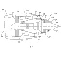
A kind of method that reduces engine noise is to increase the two-forty gas flow out from driving engine and the mixing between the free stream.Fig. 1 has shown the nozzle 20 with " V-type groove ", and " V-type groove " namely designs and be used for producing this effect.The zig-zag that the V-type groove generally comprises the certain type that is positioned at the nozzle edge is outstanding, and typically triangular in shape and have certain curvature at longitudinal cross-section, they immerse among the contiguous air-flow slightly.This V-type groove can inwardly or outwards protrude, and protrusion amount and internal face or outside wall surface upstream boundary layer thickness are in the same order of magnitude.Usually, the aspect of V-type groove can be trapezoidal or rectangle the two one of.Nozzle 20 comprises core flow pipeline 22, and the engine core air-flow is conducted through wherein; With fan stream pipeline 24, it arranges around core flow pipeline 22, and fan airstream therefrom passes through.The outlet of fan stream pipeline 24 can comprise fan stream V-type groove 19, and the outlet of core flow pipeline 22 can comprise core flow V-type groove 18.The V-type groove is typically by reducing low frequency noise with the yardstick increase engine air flow of nozzle diameter and the composite rate between the environment free air on the length.Though this method has reduced noise than the nozzle that does not have the V-type groove, but still wish further to reduce noise to meet the criteria for noise of dwelling district.
Summary of the invention
It is reader rather than limit the present invention by any way such as claim institute restricted portion for convenience that following summary is provided.Concrete aspect of the present disclosure relates to the system and method for passive guidance engine nozzle air-flow.A kind ofly comprise the aircraft nozzle that can be connected on the aircraft turbofan engine as the described system of embodiment, this nozzle comprises the first flow path wall that defines first flow path and the second flow path wall that defines second flow path.The first flow path setting receives the engine exhaust product, and the second flow path setting receives the driving engine bypass air.The first flow path wall is arranged between first and second flow paths, and the second flow path wall is arranged between second flow path and the ambient air flow path.A plurality of runners are arranged in the first and second flow path walls at least one.Runner setting comes passive guidance gas corresponding flow path in the flow path wall to arrive the corresponding flow path of this flow path wall outside by this flow path wall.Adjacent fluid channels has the outlet of extending and separating along peripheral intervals along periphery, and this outlet is arranged on the dividing range with the corresponding flow path of flow path wall outside.
Aspect further concrete, independent outlet can have corresponding closing appliance, and this system further comprises and is operably connected to the actuator that closing appliance opens and closes this outlet.In further specific embodiment, corresponding flow path terminates in the trailing edge that does not comprise the ridge (for example V-type groove) that extends back in the flow path wall.Aspect also further, independent runner does not comprise the device that the air-flow that flows through this runner is increased energy.
Other aspects of the present invention relate to the method for operate aircraft driving engine.A kind of method like this comprises the exhaust gas products of vectored flight device turbine engine along first flow path of corresponding engine nozzle, and the bypass air around the guiding driving engine is mobile along second flow path of engine nozzle.This method may further include (a) and flows to the second flow path passive guidance air-flow from first-class footpath at peripheral position intermittently, (b) flow to ambient windstream passive guidance air-flow at intermittently peripheral position from second flow path, perhaps (c) namely comprises (a) and (b) simultaneously.
Further, this method can comprise that this gas of passive guidance is by being positioned at the outlet that separates along peripheral intervals with ambient windstream dividing range place.This method can further include the outlet of selectively closing this dividing range place and reduces effective exit area of bypass air and optionally reopen these outlets with a kind of thrust corresponding to the driving engine generation and the mode of environmental conditions.
Description of drawings
Fig. 1 has schematically shown the nozzle according to prior art arrangement;
Fig. 2 has schematically shown the aircraft that has according to the nozzle of embodiments of the invention configuration;
Fig. 3 has the nozzle of the runner that arranges according to the embodiment of the invention and the simplified schematic cross-sectional view of driving engine;
Fig. 4 A has the lateral plan that is arranged on the engine nozzle of the runner between bypass gas flow and the ambient windstream according to embodiments of the invention;
Fig. 4 B is the end elevation of nozzle shown in Fig. 4 A;
Fig. 5 is the schematic cross section that has according to the runner of embodiment of the invention feature;
Fig. 6 is the diagram of curves that shows the prediction turbulent flow level of the nozzle with embodiment of the invention feature;
Fig. 7 is the diagram of curves that shows the prediction noise level of the nozzle with embodiment of the invention feature.
The specific embodiment
Content disclosed by the invention relates to and has air-flow is directed into another flow path passively from a flow path aircraft nozzle, and relevant system and method.Specific arrangement can and/or change effective exit area of nozzle in order to the effect of imitateing nozzle " V-type groove ".The detail of specific embodiment is described with reference to Fig. 2-7 below.For briefly, well-known and this method and system relevant structure or several details of method usually will no longer describe in the following description.In addition, although several embodiment of different aspect have been enumerated according to the present invention in following disclosing, than described those embodiment in this section, several other embodiment of the present invention can have different configurations or different assemblies.Therefore, the present invention may have add ons and/or other embodiment of several elements of not describing with reference to Fig. 2-7 below in addition.
Generally, the air-flow of passive guidance can be used to realize the result of following any or combination.The first, air-flow can be conducted through a plurality of runners constituting jet flow, and it is arranged to directly to imitate " hardware " (for example metal or composite material) V-type groove.Jet noise when this jet flow can be used to reduce to take off, or the vibrating noise when being used for reducing to cruise.Generally, the design of flow path can be different, and this depends on will realize that any noise reduces target.This should ascribe to, is a part at least, at the different outside flow velocity when cruising that takes off.Therefore, the designer can design flow path and solve an aforesaid noise problem particularly, (being a part at least) two noise problem that make perhaps that the geometric configuration of flow path can be adjusted so that solve.
The second, flow path can be arranged so that jet flow merges, partly the velocity gradient of mixing and reducing nozzle exit with outer flow.This is not look to causing, and a kind of eddy current produces effect, but still can reduce jet noise and vibrating noise.In addition, the geometric configuration of runner can be manufactured into to adjust and solve this two noise problem.
The 3rd, flow path can be used to change the payload space of nozzle.Variable area is used mainly to be oriented to and is reduced fan noise, but also can cause reducing of some jet noises.In addition, the geometric configuration of flow path can be manufactured into and can adjust.Even under the particular flight condition, when slit was adjusted to best fan performance, also expectation can cause at least some jet noises to reduce.The characteristic of these and other will further describe with reference to Fig. 2-7 below.
Fig. 2 has shown that commercial jet transport plane 200 has wing 202, fuselage 201 and propulsion system 203.The propulsion system 203 that shows comprises two turbofan driving engines 210 that attached by wing 202, and certainly in other embodiments, driving engine 210 can be carried by fuselage 201 or other Flight Vehicle Structures.Each driving engine 210 is incorporated in the cabin 204, and it comprises entrance 205 and nozzle 220.Nozzle 220 comprises special feature, namely reduces noise and/or changes exit area of nozzle in one or more selectable modes, will more specifically describe below.
Fig. 3 is one of them cabin 204 and relevant driving engine 210 simplified schematic cross-sectional view.In order to illustrate, a lot of internal features of driving engine 210 schematically show and/or show in simplified form.Driving engine 210 comprises compressor 212, and it receives surrounding air by entrance 205.Compressor 212 provides pressurized air for combustion chamber 214, and air and fuel mix in combustion chamber are lighted and passed through turbine 213 and expand.First or core flow path 222 around 215 flows through exhaust gas products from turbine 213 along the jet expansion Taper Pipe.Limited by first wall 221 on these first flow path, 222 profiles, and terminate in first flow path that is positioned at after the turbine 213 and export 226 places.
Turbine 213 comprises several unitary part, one of them drive compression machine 212, and another driving is placed on the fan 211 of compressor 212 fronts.Fan 211 drive bypass airs along second or fan flow path 224 around driving engine 210 core flow mistakes.Second flow path, 224 inside are defined by first wall 221, are defined by second wall 223 on the profile.This second wall 223 terminates in second flow path and exports 227 places.
Guided passively by runner 228,240 air-flow one or more in several functions can be provided.For example, the air-flow that is conducted through these runners can be taked the spray pattern of separating along peripheral intervals, the melange effect that it is produced by the top mechanical V-type groove of describing with reference to Fig. 1 in the aerodynamics simulation.Therefore, these jet flows can be strengthened the mixing between the adjacent air-flow, and can therefore reduce engine noise.In another embodiment, runner can effectively increase the exit area of engine-driven fluid circulation.In a special embodiment, this effect be used for second or fan flow path 224 to increase the available exit area of fan stream.In other words, this second runner can replenish the available exit area that second flow path exports 227 places.In other embodiments, this method can be used to first or core flow path 222 be additional on second flow path 224 or replace second flow path 224.
Fig. 4 A is the lateral plan of nozzle 220, has shown the representational embodiment of second runner 240 that places second wall 223.Therefore, second runner 240 passively steering current flow to ambient air flow path 225 from second flow path 224.The second independent runner 240 has and places the entrance 241 on second wall, 223 inside faces and place outlet 242 on second wall, 223 outside faces.Because the fan stream that is directed flowing along second flow path 224 typically has the pressure higher than the ambient air in the ambient air flow path 225, so it is sucked ambient air flow path 225 by second runner 240 by (for example passively), as shown by arrow A.
In the special embodiment shown in Fig. 4 A, contiguous is many to exporting 242 for the trapezoidal of mirror images of each other and tilting toward each other.This arrangement guides corresponding air-flow to pass the second adjacent runner 240 toward each other to simulate mechanical V-type groove.As discussed above, this effect is supposed to increase the mixing between fan airstream and the ambient windstream.In other embodiments, the shape of outlet 242 and/or second runner 240 can be different (for example, outlet 242 can be rectangle, leg-of-mutton or avette).
Fig. 4 B is the end elevation of the nozzle 220 shown in Fig. 4 A.Shown in Fig. 4 B, outlet 242 is arranged to flush with the outside face of second wall 223.Therefore, the outlet 242 do not comprise towards after step.As in following more detailed discussion, this arrangement is supposed to be beneficial to the available exit area that uses second runner 240 to flow along second flow path, 224 mobile fans with control.
Fig. 5 is the part schematic cross-sectional view that places the second representative runner 240 of second wall 223.This second runner 240 comprises the entrance 241 of level and smooth shaping and as discussed abovely is arranged to the outlet 242 that flushes with the outside face of second wall 223.Therefore, place the upstream face 243 of outlet 242 upstreams to be placed on the identical level and smooth substantially forming face with the downstream surface 244 that places outlet 242 downstreams.The air-flow that flows out outlet 242 can keep being attached on the downstream surface 244 owing to Coanda effect.
When the melange effect of V-type groove was simulated in the main configuration of second runner 240, they can (at least one embodiment) stay open in all driving engines and aircraft operation arrange.In other embodiments, second runner 240 can be closed under special driving engine setting and/or flying condition.In such embodiments, nozzle 220 can comprise closing appliance 250, and it selectively operates to close outlet 242.In the one side of this embodiment, this closing appliance 250 comprises door 251, and it is arranged on outlet 242 places and sliding opening this outlet 242 backward, closes this outlet 242 to advancing slip, as shown by arrow B.So when in the closed position, this 251 formation and upstream face 243 and downstream face 244 basic level and smooth continuous profiles.In other embodiment, door 251 can otherwise move (for example folding or rotation).Actuator 252 (being schematically illustrated among Fig. 5) is operably connected to door 251 and opens and closes this door 251.For example, each can comprise independent door 251 along the periphery extension with along the outlet 242 that peripheral intervals is separated, and the actuator 252 that shares can be used for once driving all doors 251.In other embodiments, each 251 can be controlled by independent actuator 252, and perhaps the power-transfer clutch configuration can be used for optionally opening and closing the part of specific single door 251 or door 251.In one embodiment, door 251 is only to open and to close fully movement between these two states fully, in other embodiments, according to the factor that comprises for the expectation control level of outlet 242 size and dimension, door 251 can be arranged on the position that partially opens selectively.
Controller 253 (also being schematically shown) is operably connected to actuator 252 with the motion of control gate 251, and can receive input from one or more input medias 254.In one embodiment, input media 254 can manually be controlled by the aviator and optionally open and close door 251.In another embodiment, input media 254 can comprise one or more sensors, the state of its automatic explorer vehicle driving engine and/or the flying condition of aircraft (for example, take off, climb, cruise, descend or land) and provide corresponding input for controller 253.In this embodiment, the motion that controller 253 can automatic control gate 251 and do not need aviator's interference, although if the aviator wish also can override controller 253.
Record and narrate as top, when outlet 242 was arranged to come steering current in a kind of mode of simulating the mechanical V-type effect of grooves, outlet 242 can stay open in all aircraft operation.In other cases, for example, if determine and may strengthen reducing because exporting the noise that 242 mixing that produce realize by closing some outlets that controller 253 can be used for so doing so.For example, in certain example, may expect to close or part is closed the door 251 that is positioned at nozzle 220 the latter halfs, and the door 251 that is positioned at nozzle the first half stays open.In other embodiments, reduce in the so unimportant flight condition at noise, for example, if so do the efficient of having improved propulsion system, may expect to close door 251.
In another operation mode, second runner 242 can be used to the effective exit area of fan current control that is directed flowing along second flow path 224.In the one side of this embodiment, adjacent outlet 242 is therefore towards inclining towards each other, and as shown in Fig. 2 A, but is positioned to directly steering current backward.This embodiment on the other hand in, outlet 242 can be arranged on the place that enough exports 227 upstreams away from second flow path, therefore the air-flow through adjacent channels 240 merged before arriving second flow path outlet 227 each other.Therefore, expectation merges the air-flow generation along the continuous substantially fan airstream jet flow of peripheral direction.Further expectation this basically along around the continuous fan airstream jet flow fan flow export area that will represent the exit areas that made up by outlet 242 and provide effectively increase.The advantage that this arrangement is supposed to is, owing to have the higher effective exit area, will reduce so second flow path exports the flow velocity at 227 places, and therefore this noise generated by air flow also reduces.Fig. 6 of Miao Shuing and 7 has illustrated this prediction effect subsequently.
In certain embodiments, can the 240 identical arrangements of ACTIVE CONTROL second runner intend with exit area or the V-type channel mould under different conditions, emphasizing to increase.For example, for exit area increases the biglyyest, all second runners 240 can be opened.In order to simulate the V-type groove, the second staggered runner 240 (staggered along peripheral direction) can be closed.
Fig. 6 has shown the diagram of curves of turbulence as the function of aircraft nozzle afterbody axial distance.Mark 260 has shown the observed data of two asymmetric nozzles.Line 261a has shown the turbulence value for similar nozzle prediction, and has shown that predictor roughly follows the track of observed data.Line 262a shown for shape of cross section be similar to substantially shown among Fig. 5, that separate along peripheral intervals, be arranged in the turbulence value that nozzle that second flow path exports 227 places and provide the runner 240 of (for example, with adjacent channels 240 in the air-flow that merges) continuous substantially air-flow is predicted.Fig. 6 has shown that the turbulent flow level of expectation is lower than the turbulent flow level that those do not have runner 240 as shown in Figure 5 basically, especially in the place (for example, in the distance along X-axis 0-3 times nozzle diameter) near jet expansion.
Fig. 7 has shown for the nozzle that does not have passive runner (shown in the line 261b) and has had the desired level of noise of the nozzle of passive runner (line 262b) as the function of frequency.Result displayed is under the takeoff condition.What estimated as shown in Figure 7, is to exist runner 240 as shown in Figure 5 to reduce jet noise in wide frequency range.
A characteristic of at least some previous embodiment is to have the nozzle that the runner be used for simulating mechanical V-type groove is set not need to comprise these mechanical V-type grooves itself.The advantage of this arrangement is, estimates that runner compares mechanical V-type groove and be not easy to be vibrated influence with metal fatigue, and therefore expectation infringement and need less maintenance not too easily.
The bells and whistles of at least some embodiment is that runner can be adjusted.For example, as discussed above, closing appliance can be used for optionally opening and closing runner.Its intended advantages of this arrangement is to control runner in the mode that meets noise and two targets of performance simultaneously, and described target may become another kind of flying condition from a kind of flying condition.This closing appliance comprises door, and this runner is closed in its exit at runner.The advantage of this arrangement is, when runner is closed, do not exist residual towards after step.On the contrary, when runner was closed, runner extended in level and smooth and continuous substantially mode by the outside face of this wall.
The another one characteristic of above-mentioned at least some embodiment is runner is not included as increases energy by the air-flow of runner device.For example, runner does not comprise that forced ventilation device or other are flowed out the arrangement of the pressurized air supercharging of driving engine.On the contrary, runner depends on the pressure reduction between the gas of the gas of selected nozzle wall (for example, first wall 221 or second wall 223) and this wall outside.The advantage of this arrangement is, it implements than comprising for initiatively the arrangement to the device that pressurizes for the air that is provided to runner is more convenient, and does not need blow out air from compressor or other engine sections, and it can weaken engine performance.
The another one feature of at least some embodiment recited above is runner, second runner 240 particularly, can be set up ground enough approach each other and be positioned at second flow path and export enough distant places, 227 upstreams, so can mix and provide along the continuous substantially jet flow of second wall, 223 outside faces.Arrange unlike at least some outlets, 240 of runners receive air-flows and the upstream vent window from ambient air flow path 225 admission of airs receives air-flow from any from second flow path 224.Therefore, this arrangement has effectively increased the exit area of second flow path 224.As described above, estimate that this arrangement can reduce engine noise by reducing egress rate.Increasing the additional expectation effect of exit area of nozzle is to reduce the fan back pressure.Reduce back pressure expectation and can improve flowing and reduce the noise that is produced by fan self on the fan blade.
The further advantage of aforesaid arrangement is that it can increase the performance of driving engine.For example, under high thrust condition (when for example taking off), may need is second flow path 224 area of increasing export.Under other flying conditions (when for example cruising), reduce exit area and can improve performance.Therefore, at least some embodiment, above-mentioned closing appliance can be adjusted flow area (for example opening and closing runner) by this way, and used mode depends on engine thrust setting and/or flying condition.
From above, should be understood, be illustrative purposes, described specific embodiments of the invention here, but can be made various modifications in the case of without departing from the present invention.For example, also can be used for first flow path about the described runner of second flow path above.Runner can have different internal geometry to that indicated in the drawings and outlet shape and/or arrangement.Can be combined or be excluded in further embodiments aspect described in the special embodiment some.For example, runner can be concentrated in some peripheral positions and be set to comparatively sparsely at other peripheral positions, can reduce noise and/or useful to performance better if can determine this arrangement space.In addition, though described the associated advantages of these embodiment in some embodiments of the invention, other embodiment also may show these advantages, and not every embodiment must show that these advantages are to fall within the scope of the present invention.Therefore, the present invention does not limit except appended claim is not subjected to other.
Claims (13)
1. aerocraft system comprises:
Can be connected in the aircraft nozzle of aircraft turbofan engine, this nozzle comprises:
The first flow path wall and this first flow path wall that define first flow path arrange to receive the engine exhaust product;
The second flow path wall and this second flow path setting of defining second flow path receive the driving engine bypass air, the described first flow path wall is arranged between described first and second flow paths, and the described second flow path wall is arranged between described second flow path and the ambient air flow path; With
A plurality of runners, it is arranged in the described second flow path wall, described runner setting comes described second flow path of passive guidance gas in the described second flow path wall to arrive the described ambient air flow path of the described second flow path wall outside by the described second flow path wall, and adjacent fluid channels has the adjacent outlet of extending and separating along peripheral intervals along periphery;
Wherein said outlet is arranged on the described second flow path wall;
Described aerocraft system further comprises:
Activatable closing appliance, it is arranged to be communicated with to open and close each outlet in described exit with each outlet fluid; With
Controller, it is operably connected to the operation that described closing appliance is commanded described closing appliance, wherein when described port closing, described aircraft nozzle has first exit area, and when described outlet was opened, described aircraft nozzle had second exit area bigger than described first exit area.
2. the system as claimed in claim 1 is characterized in that, described runner is shaped to guide backward gas.
3. the system as claimed in claim 1 is characterized in that, corresponding flow path terminates in the trailing edge place in the described flow path wall, the ridge that described trailing edge does not comprise at interval separately, extends back.
4. the system as claimed in claim 1 is characterized in that, each outlet has the corresponding closing appliance that is positioned at described exit, and this system further comprises and is operably connected to the actuator that described closing appliance opens and closes this outlet.
5. system as claimed in claim 4 further comprises:
Configuration is transmitted corresponding to engine condition and the flying condition input media of the incoming signal of one of them at least; With
Described controller also is operably connected to described actuator and described input media, to receive this incoming signal and at least part of operation based on the described actuator of described command input signal.
6. the system as claimed in claim 1 is characterized in that, described outlet is arranged on the trailing edge rear portion of the described second flow path wall.
7. the system described in claim 1 is characterized in that, for the contiguous flow path of corresponding outlet upstream, single runner can not pass through.
8. aerocraft system comprises:
Can be connected in the aircraft nozzle of aircraft turbofan engine, this nozzle comprises:
The first flow path wall and this first flow path wall that define first flow path arrange to receive the engine exhaust product;
The second flow path wall and this second flow path wall that define second flow path arrange to receive the driving engine bypass air, the described first flow path wall is arranged between described first and second flow paths, and the described second flow path wall is arranged between described second flow path and the ambient air flow path; With
A plurality of runners, it is arranged in the described second flow path wall, described runner setting comes described second flow path of passive guidance gas in the described second flow path wall to arrive the described ambient air flow path of the described second flow path wall outside by the described second flow path wall, and adjacent fluid channels has the adjacent outlet of extending and separating along peripheral intervals along periphery;
Wherein said outlet is arranged on the described first flow path wall;
Described aerocraft system further comprises:
Activatable closing appliance, it is arranged to be communicated with to open and close each outlet in described exit with each outlet fluid; With
Controller, it is operably connected to the operation that described closing appliance is commanded described closing appliance, wherein when described port closing, described aircraft nozzle has first exit area, and when described outlet was opened, described aircraft nozzle had second exit area bigger than described first exit area.
9. method that is used for the operate aircraft driving engine comprises:
Exhaust gas products along the first flow path vectored flight device turbofan engine of corresponding engine nozzle;
Second flow path guiding driving engine bypass air on every side along described engine nozzle;
(a) at interval peripheral position from described first flow path to the described second flow path passive guidance gas, (b) at interval the position that periphery extends and peripheral intervals is separated from described second flow path to ambient windstream passive guidance gas, perhaps (c) namely comprises (a) and (b) simultaneously; Wherein passive guidance gas comprise the described gas of guiding from second flow path by being positioned at the outlet that separates along peripheral intervals with described ambient windstream intersection, wherein this method further comprises the outlet of optionally closing described intersection reducing effective exit area of bypass air, and optionally reopens this outlet in the mode of the thrust that produces corresponding to described driving engine and environmental conditions.
10. method as claimed in claim 9, it is characterized in that, passive guidance gas be included in gas from (a) described first flow path, (b) described second flow path or (c) namely comprise simultaneously (a) and (b) flow out after, be that described gas increases under the situation of energy and guides described gas.
11. method as claimed in claim 9, it is characterized in that, described aircraft engine comprises the engine nozzle with V-type groove, this V-type groove is that the zig-zag that is positioned on the nozzle edge is outstanding, and passive guidance gas is included under the situation of the engine nozzle that does not use described V-type groove described gas is mixed with ambient windstream.
12. method as claimed in claim 9, it is characterized in that, described aircraft engine comprises the engine nozzle with V-type groove, this V-type groove is that the zig-zag that is positioned on the nozzle edge is outstanding, and at least part of simulation of passive guidance gas is because described V-type groove is present in the exit of the exit of described first flow path, described second flow path or air-flow mixing that both exits cause.
13. method as claimed in claim 9 is characterized in that, passive guidance gas comprises that from described second flow path to described ambient windstream guiding velocity ratio described ambient windstream flow velocity is big and than the little gas of described bypass air flow velocity.
Applications Claiming Priority (2)
| Application Number | Priority Date | Filing Date | Title |
|---|---|---|---|
| US11/635,737 US7870722B2 (en) | 2006-12-06 | 2006-12-06 | Systems and methods for passively directing aircraft engine nozzle flows |
| US11/635,737 | 2006-12-06 |
Publications (2)
| Publication Number | Publication Date |
|---|---|
| CN101200220A CN101200220A (en) | 2008-06-18 |
| CN101200220B true CN101200220B (en) | 2013-08-14 |
Family
ID=39144413
Family Applications (1)
| Application Number | Title | Priority Date | Filing Date |
|---|---|---|---|
| CN2007103068896A Expired - Fee Related CN101200220B (en) | 2006-12-06 | 2007-12-06 | Systems and methods for passively directing aircraft engine nozzle flows |
Country Status (5)
| Country | Link |
|---|---|
| US (2) | US7870722B2 (en) |
| EP (1) | EP1936172B1 (en) |
| JP (1) | JP5241215B2 (en) |
| CN (1) | CN101200220B (en) |
| ES (1) | ES2391115T3 (en) |
Families Citing this family (34)
| Publication number | Priority date | Publication date | Assignee | Title |
|---|---|---|---|---|
| US20090261206A1 (en) * | 2005-01-21 | 2009-10-22 | Alvi Farrukh S | Method of using microjet actuators for the control of flow separation and distortion |
| US8157207B2 (en) * | 2006-08-09 | 2012-04-17 | The Boeing Company | Jet engine nozzle exit configurations, including projections oriented relative to pylons, and associated systems and methods |
| US7966824B2 (en) * | 2006-08-09 | 2011-06-28 | The Boeing Company | Jet engine nozzle exit configurations and associated systems and methods |
| US7870722B2 (en) * | 2006-12-06 | 2011-01-18 | The Boeing Company | Systems and methods for passively directing aircraft engine nozzle flows |
| US7966826B2 (en) * | 2007-02-14 | 2011-06-28 | The Boeing Company | Systems and methods for reducing noise from jet engine exhaust |
| US9701415B2 (en) | 2007-08-23 | 2017-07-11 | United Technologies Corporation | Gas turbine engine with axial movable fan variable area nozzle |
| US10167813B2 (en) | 2007-08-23 | 2019-01-01 | United Technologies Corporation | Gas turbine engine with fan variable area nozzle to reduce fan instability |
| US9494084B2 (en) * | 2007-08-23 | 2016-11-15 | United Technologies Corporation | Gas turbine engine with fan variable area nozzle for low fan pressure ratio |
| FR2929335B1 (en) * | 2008-03-31 | 2012-06-01 | Airbus France | NOISE REDUCTION DEVICE GENERATED BY AN AIRCRAFT REACTOR WITH FLUID JETS OF THE SAME ORIENTATION |
| FR2929337B1 (en) * | 2008-03-31 | 2012-06-01 | Airbus France | SECONDARY JET DEVICE FOR REDUCING NOISE GENERATED BY AN AIRCRAFT REACTOR |
| FR2929336B1 (en) * | 2008-03-31 | 2012-06-01 | Airbus France | JET DEVICE NOISE REDUCTION PLATES GENERATED BY AN AIRCRAFT REACTOR |
| FR2929334B1 (en) * | 2008-03-31 | 2012-06-01 | Airbus France | DEVICE FOR REDUCING NOISE GENERATION BY AIRCRAFT REACTOR WITH BLEED FLUID CONDUITS |
| US8087250B2 (en) * | 2008-06-26 | 2012-01-03 | General Electric Company | Duplex tab exhaust nozzle |
| FR2934009B1 (en) * | 2008-07-21 | 2010-09-03 | Ge Energy Products France Snc | EXHAUST DIFFUSER FOR GAS TURBINE |
| US9885313B2 (en) | 2009-03-17 | 2018-02-06 | United Technologes Corporation | Gas turbine engine bifurcation located fan variable area nozzle |
| US8714919B2 (en) * | 2009-11-06 | 2014-05-06 | Raytheon Company | Inlet and exhaust system |
| GB201007215D0 (en) | 2010-04-30 | 2010-06-16 | Rolls Royce Plc | Gas turbine engine |
| GB201016455D0 (en) | 2010-09-30 | 2010-11-17 | Imp Innovations Ltd | Fluid flow modification |
| FR2971553B1 (en) * | 2011-02-10 | 2015-05-29 | Eads Europ Aeronautic Defence | REACTOR WITH REDUCED ACOUSTIC SIGNATURE |
| FR2978989B1 (en) * | 2011-08-12 | 2013-07-26 | Aircelle Sa | EJECTION CONE FOR AIRCRAFT TURBOJET ENGINE |
| ES2621658T3 (en) * | 2012-08-09 | 2017-07-04 | MTU Aero Engines AG | Conductive current arrangement for cooling the low pressure turbine housing of a gas turbine jet engine |
| GB201220378D0 (en) * | 2012-11-13 | 2012-12-26 | Rolls Royce Plc | A gas turbine engine exhaust nozzle |
| JP6183837B2 (en) | 2013-08-19 | 2017-08-23 | 国立研究開発法人宇宙航空研究開発機構 | Exhaust nozzle |
| FR3016863B1 (en) * | 2014-01-29 | 2017-05-26 | Snecma | NACELLE FOR AIRCRAFT TURBO AIRCRAFT |
| US10094332B2 (en) | 2014-09-03 | 2018-10-09 | The Boeing Company | Core cowl for a turbofan engine |
| US10711702B2 (en) * | 2015-08-18 | 2020-07-14 | General Electric Company | Mixed flow turbocore |
| US10563613B2 (en) | 2015-08-31 | 2020-02-18 | Rolls-Royce North American Technologies Inc. | Coanda device for a round exhaust nozzle |
| WO2018048649A1 (en) * | 2016-09-08 | 2018-03-15 | Unison Industries, Llc | Fan casing assembly with cooler |
| CN108019295B (en) * | 2017-12-15 | 2021-03-30 | 中国航发沈阳发动机研究所 | Turbulent flow noise reduction device for aircraft engine |
| GB201820936D0 (en) * | 2018-12-21 | 2019-02-06 | Rolls Royce Plc | Low noise gas turbine engine |
| US11440671B2 (en) * | 2019-01-24 | 2022-09-13 | Amazon Technologies, Inc. | Adjustable motor fairings for aerial vehicles |
| FR3095241B1 (en) * | 2019-04-17 | 2021-06-25 | Safran Aircraft Engines | Turbojet nacelle air inlet comprising a circulation pipe to promote a thrust reversal phase |
| CA3145745A1 (en) * | 2019-07-01 | 2021-01-07 | Chuanrui ZHANG | Aerodynamic techniques and methods for quieter supersonic flight |
| JP7297574B2 (en) | 2019-07-12 | 2023-06-26 | 三菱重工業株式会社 | GAS TURBINE SYSTEM AND MOVING OBJECT WITH THE SAME |
Family Cites Families (55)
| Publication number | Priority date | Publication date | Assignee | Title |
|---|---|---|---|---|
| GB1127659A (en) | 1966-09-16 | 1968-09-18 | Rolls Royce | Improvements in gas turbine engines |
| US3568792A (en) | 1969-06-18 | 1971-03-09 | Rohr Corp | Sound-suppressing and thrust-reversing apparatus |
| FR2091911B1 (en) | 1970-04-21 | 1974-03-01 | Snecma | |
| US3648800A (en) * | 1970-04-27 | 1972-03-14 | Gen Electric | Coanda expansion exhaust nozzle suppressor |
| FR2126922B1 (en) * | 1971-01-20 | 1975-01-17 | Snecma | |
| US4043522A (en) * | 1975-12-22 | 1977-08-23 | The Boeing Company | Common pod for housing a plurality of different turbofan jet propulsion engines |
| US4372110A (en) * | 1976-02-13 | 1983-02-08 | Nasa | Noise suppressor for turbo fan jet engines |
| US4215536A (en) * | 1978-12-26 | 1980-08-05 | The Boeing Company | Gas turbine mixer apparatus |
| GB2104967B (en) * | 1981-09-03 | 1985-07-17 | Rolls Royce | Exhaust mixer for turbofan aeroengine |
| EP0102953A4 (en) * | 1982-03-17 | 1984-08-10 | Boeing Co | Internally ventilated noise suppressor with large plug nozzle. |
| US4819425A (en) * | 1982-03-18 | 1989-04-11 | The Boeing Company | Primary-secondary ventilated flow mixer nozzle for high bypass turbo fan jet propulsion system |
| GB2146702B (en) | 1983-09-14 | 1987-12-23 | Rolls Royce | Exhaust mixer for turbofan aeroengine |
| GB2149456B (en) | 1983-11-08 | 1987-07-29 | Rolls Royce | Exhaust mixing in turbofan aeroengines |
| GB2207468A (en) | 1987-06-01 | 1989-02-01 | Secr Defence | Vortex silencing in gas turbine engines |
| US5117628A (en) | 1990-01-25 | 1992-06-02 | General Electric Company | Mixed flow augmentor pre-mixer |
| US5884472A (en) * | 1995-10-11 | 1999-03-23 | Stage Iii Technologies, L.C. | Alternating lobed mixer/ejector concept suppressor |
| US5924632A (en) * | 1996-05-02 | 1999-07-20 | The United States Of America As Represented By The Administrator Of The National Aeronautics And Space Administration | Jet nozzle having centerbody for enhanced exit area mixing |
| US6082635A (en) * | 1996-06-12 | 2000-07-04 | The United States Of America As Represented By The Administrator Of The National Aeronautics And Space Administration | Undulated nozzle for enhanced exit area mixing |
| US5947412A (en) * | 1997-01-10 | 1999-09-07 | Titan Corporation | Jet engine noise suppressor assembly |
| US6360528B1 (en) | 1997-10-31 | 2002-03-26 | General Electric Company | Chevron exhaust nozzle for a gas turbine engine |
| US6314721B1 (en) * | 1998-09-04 | 2001-11-13 | United Technologies Corporation | Tabbed nozzle for jet noise suppression |
| US6578355B1 (en) | 1999-03-05 | 2003-06-17 | Rolls-Royce Deutschland Ltd & Co Kg | Bloom mixer for a turbofan engine |
| US6612106B2 (en) * | 2000-05-05 | 2003-09-02 | The Boeing Company | Segmented mixing device having chevrons for exhaust noise reduction in jet engines |
| EP1322854A4 (en) | 2000-10-02 | 2004-08-04 | Rohr Inc | Apparatus, method and system for gas turbine engine noise reduction |
| US6640537B2 (en) * | 2000-12-18 | 2003-11-04 | Pratt & Whitney Canada Corp. | Aero-engine exhaust jet noise reduction assembly |
| US6837456B1 (en) * | 2001-01-10 | 2005-01-04 | Florida State University Research Foundation | Microjet based control system |
| GB0105349D0 (en) | 2001-03-03 | 2001-04-18 | Rolls Royce Plc | Gas turbine engine exhaust nozzle |
| US6532729B2 (en) * | 2001-05-31 | 2003-03-18 | General Electric Company | Shelf truncated chevron exhaust nozzle for reduction of exhaust noise and infrared (IR) signature |
| DE10145489B4 (en) * | 2001-09-14 | 2008-11-06 | Mtu Aero Engines Gmbh | Arrangement for mixing two originally separately guided fluid streams in a two-circuit jet engine |
| WO2003036063A2 (en) * | 2001-10-23 | 2003-05-01 | The Nordam Group, Inc. | Confluent variable exhaust nozzle |
| EP1485600B1 (en) * | 2002-02-22 | 2009-11-04 | THE NORDAM GROUP, Inc. | Duplex mixer exhaust nozzle |
| US6658839B2 (en) * | 2002-02-28 | 2003-12-09 | The Boeing Company | Convergent/divergent segmented exhaust nozzle |
| GB0205701D0 (en) * | 2002-03-12 | 2002-04-24 | Rolls Royce Plc | Variable area nozzle |
| US7293401B2 (en) * | 2002-03-20 | 2007-11-13 | The Regents Of The University Of California | Jet engine noise suppressor |
| US6983912B2 (en) * | 2002-04-30 | 2006-01-10 | The Boeing Company | Hybrid exhaust heat shield for pylon mounted gas turbine engines |
| US6718752B2 (en) * | 2002-05-29 | 2004-04-13 | The Boeing Company | Deployable segmented exhaust nozzle for a jet engine |
| GB0226228D0 (en) * | 2002-11-09 | 2002-12-18 | Rolls Royce Plc | Suppression of part of the noise from a gas turbine engine |
| US6969028B2 (en) | 2003-01-22 | 2005-11-29 | The Boeing Company | Scarf nozzle for a jet engine and method of using the same |
| US7010905B2 (en) | 2003-02-21 | 2006-03-14 | The Nordam Group, Inc. | Ventilated confluent exhaust nozzle |
| US6971229B2 (en) * | 2003-02-26 | 2005-12-06 | The Nordam Group, Inc. | Confluent exhaust nozzle |
| US7055329B2 (en) * | 2003-03-31 | 2006-06-06 | General Electric Company | Method and apparatus for noise attenuation for gas turbine engines using at least one synthetic jet actuator for injecting air |
| FR2855558B1 (en) | 2003-05-28 | 2005-07-15 | Snecma Moteurs | TURBOMACHINE TUBE WITH NOISE REDUCTION |
| FR2857416B1 (en) * | 2003-07-09 | 2007-05-25 | Snecma Moteurs | DEVICE FOR REDUCING JET NOISE OF A TURBOMACHINE |
| FR2868131B1 (en) * | 2004-03-25 | 2006-06-09 | Airbus France Sas | PRIME TUBE WITH CHEVRONS FOR A DOUBLE FLOW AIRCRAFT AIRCRAFT AND AIRCRAFT COMPRISING SUCH TUYERE |
| US7246481B2 (en) | 2004-03-26 | 2007-07-24 | General Electric Company | Methods and apparatus for operating gas turbine engines |
| FR2872549B1 (en) * | 2004-07-05 | 2006-09-22 | Centre Nat Rech Scient Cnrse | AIRCRAFT REACTOR EQUIPPED WITH A NOISE REDUCTION DEVICE FOR PROPELLANT JETS |
| US7246451B2 (en) * | 2004-09-30 | 2007-07-24 | Technophar Equipment & Service Limited | Tumbler-dryer for capsules |
| GB0505246D0 (en) | 2005-03-15 | 2005-04-20 | Rolls Royce Plc | Engine noise |
| US7559538B2 (en) | 2006-01-27 | 2009-07-14 | Dbs Manufacturing, Inc. | Wastewater treatment system and method of using same |
| US7721551B2 (en) * | 2006-06-29 | 2010-05-25 | United Technologies Corporation | Fan variable area nozzle for a gas turbine engine fan nacelle |
| US8157207B2 (en) * | 2006-08-09 | 2012-04-17 | The Boeing Company | Jet engine nozzle exit configurations, including projections oriented relative to pylons, and associated systems and methods |
| US7966824B2 (en) | 2006-08-09 | 2011-06-28 | The Boeing Company | Jet engine nozzle exit configurations and associated systems and methods |
| US7520124B2 (en) | 2006-09-12 | 2009-04-21 | United Technologies Corporation | Asymmetric serrated nozzle for exhaust noise reduction |
| US8015819B2 (en) * | 2006-09-29 | 2011-09-13 | The United States Of America As Represented By The Administrator Of The National Aeronautics And Space Administration | Wet active chevron nozzle for controllable jet noise reduction |
| US7870722B2 (en) | 2006-12-06 | 2011-01-18 | The Boeing Company | Systems and methods for passively directing aircraft engine nozzle flows |
-
2006
- 2006-12-06 US US11/635,737 patent/US7870722B2/en not_active Expired - Fee Related
-
2007
- 2007-12-06 CN CN2007103068896A patent/CN101200220B/en not_active Expired - Fee Related
- 2007-12-06 EP EP07122560A patent/EP1936172B1/en not_active Not-in-force
- 2007-12-06 JP JP2007315963A patent/JP5241215B2/en not_active Expired - Fee Related
- 2007-12-06 ES ES07122560T patent/ES2391115T3/en active Active
-
2010
- 2010-12-07 US US12/961,808 patent/US8166768B2/en active Active
Also Published As
| Publication number | Publication date |
|---|---|
| JP5241215B2 (en) | 2013-07-17 |
| US20110072781A1 (en) | 2011-03-31 |
| JP2008144764A (en) | 2008-06-26 |
| EP1936172A2 (en) | 2008-06-25 |
| ES2391115T3 (en) | 2012-11-21 |
| US20080134665A1 (en) | 2008-06-12 |
| CN101200220A (en) | 2008-06-18 |
| EP1936172A3 (en) | 2010-04-21 |
| US7870722B2 (en) | 2011-01-18 |
| EP1936172B1 (en) | 2012-07-11 |
| US8166768B2 (en) | 2012-05-01 |
Similar Documents
| Publication | Publication Date | Title |
|---|---|---|
| CN101200220B (en) | Systems and methods for passively directing aircraft engine nozzle flows | |
| US8096105B2 (en) | Turbojet engine with attenuated jet noise | |
| RU2723371C2 (en) | Traction recovery exhaust valves for use with aircraft | |
| RU2499739C2 (en) | Supersonic aircraft jet engine | |
| US7966826B2 (en) | Systems and methods for reducing noise from jet engine exhaust | |
| US3664612A (en) | Aircraft engine variable highlight inlet | |
| EP1438494B1 (en) | Confluent variable exhaust nozzle | |
| US20090212165A1 (en) | Passive removal of suction air for laminar flow control, and associated systems and methods | |
| US4422524A (en) | Variable shape, fluid flow nozzle for sound suppression | |
| US7469529B2 (en) | Chevron-type primary exhaust nozzle for aircraft turbofan engine, and aircraft comprising such a nozzle | |
| US7726609B2 (en) | High-performance low-noise aircraft exhaust systems and methods | |
| EP2060769B1 (en) | Thrust reverser | |
| US9587585B1 (en) | Augmented propulsion system with boundary layer suction and wake blowing | |
| US5216878A (en) | Mixed exhaust flow supersonic jet engine and method | |
| CN101297107B (en) | Turbofan engine for stol aircraft | |
| JPH0737240B2 (en) | Mixed laminar flow nacelle | |
| US20170191447A1 (en) | Ultra hush exhaust system (uhes) | |
| US5222359A (en) | Nozzle system and method for supersonic jet engine | |
| US9969497B2 (en) | Noise and drag reducing cabin pressure outflow valve | |
| US20110240804A1 (en) | Integrated aircraft | |
| CN103987948A (en) | Nozzle arrangement and method of making the same | |
| RU2731780C2 (en) | Device with grids for ejection of microjets to reduce noise of jet stream of gas turbine engine | |
| CN103890349A (en) | Air inlet arrangement and method of making the same | |
| US6178742B1 (en) | Rear mixer ejector for a turbomachine |
Legal Events
| Date | Code | Title | Description |
|---|---|---|---|
| C06 | Publication | ||
| PB01 | Publication | ||
| C10 | Entry into substantive examination | ||
| SE01 | Entry into force of request for substantive examination | ||
| C14 | Grant of patent or utility model | ||
| GR01 | Patent grant | ||
| CF01 | Termination of patent right due to non-payment of annual fee | ||
| CF01 | Termination of patent right due to non-payment of annual fee |
Granted publication date: 20130814 |