CN101188183B - Mass spectrometer and method of mass spectrometry - Google Patents
Mass spectrometer and method of mass spectrometry Download PDFInfo
- Publication number
- CN101188183B CN101188183B CN200710085081XA CN200710085081A CN101188183B CN 101188183 B CN101188183 B CN 101188183B CN 200710085081X A CN200710085081X A CN 200710085081XA CN 200710085081 A CN200710085081 A CN 200710085081A CN 101188183 B CN101188183 B CN 101188183B
- Authority
- CN
- China
- Prior art keywords
- ion
- quality
- electromotive force
- utmost point
- bar electrode
- Prior art date
- Legal status (The legal status is an assumption and is not a legal conclusion. Google has not performed a legal analysis and makes no representation as to the accuracy of the status listed.)
- Expired - Fee Related
Links
Images


Classifications
-
- H—ELECTRICITY
- H01—ELECTRIC ELEMENTS
- H01J—ELECTRIC DISCHARGE TUBES OR DISCHARGE LAMPS
- H01J49/00—Particle spectrometers or separator tubes
- H01J49/26—Mass spectrometers or separator tubes
- H01J49/34—Dynamic spectrometers
- H01J49/42—Stability-of-path spectrometers, e.g. monopole, quadrupole, multipole, farvitrons
- H01J49/4205—Device types
- H01J49/422—Two-dimensional RF ion traps
- H01J49/4225—Multipole linear ion traps, e.g. quadrupoles, hexapoles
-
- H—ELECTRICITY
- H01—ELECTRIC ELEMENTS
- H01J—ELECTRIC DISCHARGE TUBES OR DISCHARGE LAMPS
- H01J49/00—Particle spectrometers or separator tubes
- H01J49/26—Mass spectrometers or separator tubes
- H01J49/34—Dynamic spectrometers
- H01J49/42—Stability-of-path spectrometers, e.g. monopole, quadrupole, multipole, farvitrons
- H01J49/426—Methods for controlling ions
- H01J49/427—Ejection and selection methods
- H01J49/429—Scanning an electric parameter, e.g. voltage amplitude or frequency
Abstract
The quality analysis meter and the quality analysis device of the invention consists of a fourfold point rod electrode importing an ion generated by an ion source applying RF voltage and a detection mechanism for detecting the excluded ion. The invention is characterized in that an electric potential with quality is formed at the axial direction of the rod and the ion is excluded to the axial direction selectively near the minimum point of the electric potential. Besides, through applying electrostatic voltage and RF voltage at the inserting electrode between the inserting rod electrodes, the electric potential choosing quality is formed. According to the invention, a linear pitfall with high discharging efficiency and low discharging energy is realized.
Description
Technical field
The present invention relates to quality analysis apparatus and method of work thereof.
Background technology
Linear trap can be carried out MS in inside
nAnalyze extensive use in Proteomic analysis.Illustrate that below the ion that how to carry out being caught by linear trap in the prior art carries out the ion discharge that quality is selected.
The example that the ion of selecting as the quality in the linear trap is discharged is documented in United States Patent (USP) the 5th, 420, in No. 425.After putting aside in linear trap from the ion of axial incident, carry out ion as required and select or ion dissociation.Then, between relative a pair of quadruple utmost point bar electrode, apply auxiliary AC field, can make the extra fine quality ion at resonance excitation radially.By scan capture RF voltage, quality selects geocentric vertical to discharge ion.The pseudo-electromotive force of the mediation that will be formed by quadruple utmost point electric field radially is used in the mass separation mass resolution height.
In addition, select the example of discharging, be documented in United States Patent (USP) the 6th, 177, in No. 668 as the quality of linear trap.Putting aside behind the ion of axial incident, carrying out ion as required and select and ionic dissociation.Then, between relative a pair of quadruple utmost point bar electrode, apply auxiliary AC field, radially encouraging ion.Utilize the fringing field (fringing field) that produces between quadruple utmost point bar electrode and the terminal electrode, will be at the ion of resonance excitation radially to axial discharge.Frequency of assisting AC field or the amplitude of catching RF voltage are scanned.The pseudo-electromotive force of mediation that is formed by radially quadruple utmost point electric field uses the mass resolution height in mass separation.
In addition, select the example of discharging, be documented in United States Patent (USP) the 5th, 783, in No. 824 as the quality of linear trap.Savings is from the ion of axial incident.Between quadruple utmost point bar electrode, insert blade electrode,, on the linear trap axle, form the mediation electromotive force by the DC bias voltage between blade electrode and the quadruple utmost point bar electrode.Then, by between blade electrode, applying auxiliary AC field, resonance excitation ion, quality selection geocentric vertical discharge ion.Frequency to DC bias voltage or auxiliary alternating voltage scans.
At United States Patent (USP) the 6th, 852, put down in writing from the mode of three-dimensional ion trap in No. 972 with low-yield discharge ion.When three-dimensional ion trap is discharged ion, between end cap, apply dc voltage and scan RF voltage, in view of the above will be from high-quality ion to low-quality ion, the quality method of selectively discharging successively.Owing to discharge ion near the energy level point, the exhaust energy expansion is the room temperature level.
In addition,, put down in writing between quadruple utmost point bar electrode in No. 386 and inserted electrode, axially formed electric field, controlled the method for ion action at United States Patent (USP) the 5th, 847.Utilize quadruple utmost point bar electrode and insert potential difference between the electrode, carry out ion efflux time short timeization or catch.
Summary of the invention
Technical problem to be solved by this invention is, the linear trap that can carry out the dispersion of exhaust energy is suppressed at the quality selection discharge of room temperature level (number 10meV level) is provided.Linear trap is compared with existing three-dimensional ion trap, has excellent character such as capture rate height, charge capacity are big, can be used in combination with other mass analyzer.And in flight time type mass analyzer, orbitrap type mass analyzer, quadruple polar form mass analyzer etc., very narrow for the allowed band of the energy spread of incident ion.Therefore, if keep energy spread to carry out ion incidence, will cause the minimizing of ion transmission, the reduction of quality resolution to ground more than the allowed band.Therefore, if the dispersion of exhaust energy is suppressed at the room temperature level, linear trap just can be efficiently combines with the narrow mass analyzer of the allowed band of incident ionic energies expansions such as flight time type mass analyzer, orbitrap type mass analyzer, quadruple polar form mass analyzer.
At United States Patent (USP) the 5th, 420, under No. 425 the situation, ion is to radially discharging.Voltage in the kV level that applies on the quadruple utmost point bar electrode is applied in when discharging, and exhaust energy expands to more than several 100eV.
At United States Patent (USP) the 6th, 177, under No. 668 the situation, in the discharge of ion, use resonance excitation.In these methods, be to discharging the mode that ion provides energy to surmount potential barrier selectively,, making energy spread wittingly from the room temperature level so must pay energy to discharging ion.
At United States Patent (USP) the 6th, 852, put down in writing three-dimensional ion trap in No. 972, but do not related to quality is selectively discharged ion from linear trap record and hint fully.
At United States Patent (USP) the 5th, 847, put down in writing in No. 386 and do not exist with ... quality ground and under the DC electromotive force, carry out ion control, selectively do not carry out record and the hint that ion is discharged but relate to quality fully.
Problem of the present invention is, the linear trap that can carry out the dispersion of exhaust energy is suppressed at the discharge that the quality of room temperature level (number 10meV level) selects is provided.
Mass analyzer of the present invention and quality analysis apparatus are made of with ion and quadruple utmost point bar electrode that applies RF voltage and the testing agency of detecting the ion of being discharged that ion source generates importing, it is characterized in that:
1) have the parts that axially form the interdependent electromotive force of quality at rod, near the quality minimal point of this electromotive force selectively to axial discharge ion;
2) in addition, this electromotive force forms parts in order to form the electromotive force that quality is selected, and applies electrostatic potential and RF voltage on the insertion electrode that is inserted between the bar electrode.
According to the present invention, realized to carry out the dispersion of exhaust energy is suppressed at the linear trap of the discharge that the quality of room temperature level (number 10meV level) selects.
Description of drawings
Figure 1A and Figure 1B are the embodiment 1 of present embodiment.
Fig. 2 is the mensuration sequence of embodiment 1.
Fig. 3 is the mensuration sequence of embodiment 1.
Fig. 4 is the key diagram of the effect of present embodiment.
Fig. 5 A~5D is the key diagram of the effect of present embodiment.
Fig. 6 is the embodiment 2 of present embodiment.
Fig. 7 is the embodiment 3 of present embodiment.
Embodiment
(embodiment 1)
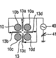
Figure 1A and 1B are the structure charts of quality analysis of implementing the linear trap of the manner.Figure 1A is that device is all schemed, and Figure 1B is the radial cross-section of device.The ion that is generated by the ion source 1 of electric spray ion source, atmospheric pressure chemical ion source, atmospheric pressure photoion source, the substance assistant laser desorpted ion source of atmospheric pressure, substance assistant laser desorpted ion source etc. is imported in the differential exhaust portion 5 by pore 2.Pump 30 exhausts of differential exhaust portion.By differential exhaust, ion is imported into analysis portion 6 by pore 3.Analysis portion maintains 10 with pump 31 exhausts
-4Torr following (1.3 * 10
-2Pa is following).The ion that has passed through the ion delivery section 4 that is made of ion lens, quadruple utmost point filter, linear trap etc. is imported into linear trap portion 7 by pore 17.Linear trap portion 7 is imported buffer gas (not shown), maintain 10
-4Torr~10
-2Torr (1.3 * 10
-2Pa~1.3Pa).The ion that is imported into is caught by the zone that is clipped by insertion electrode 13 between entrance side termination electrode 11, quadruple utmost point bar electrode 10, the insertion quadruple utmost point bar electrode and outlet side termination electrode 12.On inserting electrode, apply dc voltage 41 and RF voltage 40 (when only being recited as dc voltage, RF voltage later on, being defined as this voltage).By the ion of this areas captured the amplitude of RF voltage 40 or at least one of frequency or dc voltage value are changed, the ion of extra fine quality number is to axially being discharged from.The shape of inserting electrode be outlet one side than at the inlet side of ion in the big shape of radial width.As an example, represent the example of curvilinear insertion electrode here.Represented curvilinear insertion electrode in the drawings, but in addition, also can electrode shape be optimized for efficiently in the shape of axially drawing ion by emulation.The ion of discharging imports to flight time type quality analysis portion 25 by behind the pore 20.The ion that imports to flight time type quality analysis portion 25 quickens at orthogonal direction with specific period by releasing accelerating electrode 21, by drawing after accelerating electrode 22 quickens, by reflecting electrode 23 reflections, is waited detector 24 detections that constitute by MCP (microchannel plate).Can know mass number according to the time that accelerates to detection from release, and can know ionic strength, so can obtain mass spectrum according to signal strength signal intensity.
Though also have on the drift potential of quadruple utmost point bar electrode 10, electrode voltage by front and back applies ± counts the scheme of 100V voltage, but following when the voltage of each electrode of recording and narrating quadruple utmost point bar electrode 10, be defined as the drift potential that makes quadruple utmost point bar electrode 10 and be 0 o'clock value.Applying the amplitude (high frequency voltage (catching RF voltage) about 100V~5000V, frequency 500kHz~2MHz) on the quadruple utmost point bar electrode 10.At this moment, relative quadruple utmost point bar electrode is (among the figure (10a, 10c) and (10b, 10d), below according to this definition) apply the synchronous RF of catching voltage, and on adjacent quadruple utmost point bar electrode ((10a, 10b), (10b, 10c), (10c, 10d) and (10d, 10a) among the figure, below according to this definition), apply opposite phase catch RF voltage.By applying RF voltage, producing pseudo-electromotive force with the quadruple direction that extremely rod is axially vertical (below be defined as radially) to above-mentioned quadruple utmost point bar electrode.Therefore, generation is to the convergence electromotive force of axle center position.Therefore, the radial distribution of ion becomes from central shaft and begins in 1~2mm.
Below describe with regard to the voltage that typically applies of positive ion composition.Fig. 2 represents to measure sequence.Measure with 4 sequences.In the ion savings time, the entrance side termination electrode is set at 20V, is set at 20V (just dc voltage) inserting electrode.Since quadruple utmost point electric field radially formed pseudo-electromotive force by catching RF voltage, then formed the DC electromotive force at the central axis direction of quadruple utmost point electric field, so caught by outlet side termination electrode 12 peripheries by the ion of pore 17 in port of export direction.At RF axial electromotive force DC electric field was only arranged in time, the quality ground that the electromotive force minimal point does not exist with ... ion is positioned near the port of export, so most ion is caught near the port of export.The length of capture time is about 1ms~1000ms, greatly exists with ... the iontophoresis amount to linear trap.If capture time is long, ionic weight just increases, in the inner phenomenon that is called space charge of linear trap.If the generation space charge, during the mass scanning of just describing in the back, the problem that move the position of generation spectrum mass number.On the contrary,, just produce statistical error, can't obtain mass spectrum with sufficient S/N if ionic weight is very few.In order to select suitable capture time, with device supervision ionic weight and the automatic length of adjusting capture time also are effective arbitrarily.
Then the RF voltage amplitude that the insertion electrode is applied is increased to about 10~100V from 0 at RF.The frequency setting of RF voltage is about 300kHz~3MHz.In view of the above, at the pseudo-electromotive force that axially forms based on RF.As an example that inserts electrode, below expression is inserted 4 decentre wheelbases from the result of calculation of d during by the tabular insertion electrode of formula 1 expression.
(f: axial distance (0~22mm) L: the extremely excellent length 22mm of axial length=quadruple that inserts electrode)
Fig. 4 represents the pseudo-electromotive force that amplitude is 20V, above-mentioned RF voltage formed when frequency was 1MHz.As pseudo-electromotive force Ψ, use formula 1 is represented.
(e: the plain amount of electronics, m: mass of ion, Ω: each frequency of RF voltage, the electric field strength amplitude of the formation of E:RF voltage)
Know that from this mathematical expression pseudo-electromotive force and quality that identical RF electric field produces are inversely proportional to.In time, the minimal point of axial electromotive force (the pseudo-electromotive force of Fig. 4 and the synthetic electromotive force of DC electromotive force) does not exist with ... the quality of ion, is positioned near the port of export, so whole ions is caught near the port of export at RF.
Then at DC in time, be applied to the dc voltage value inserted on the electrode from+20V to-20V variation.Fig. 5 A represents according to dc voltage at this moment, the electromotive force that RF voltage is synthesized.In time, the minimal point difference of axial electromotive force is so be hunted down at axial diverse location according to mass distribution at DC.
At last in efflux time, the outlet termination electrode is changed to about 0V from+20V.In view of the above, has only near the ion in end to axial discharge.From Fig. 5 A just now, low-quality ion (m/z 100) has minimal point near the end, so discharged by ion.
In addition, be applied to the dc voltage that inserts on the electrode from-20V to 0V scanning (solid line Fig. 2), perhaps be applied to the RF amplitude that inserts on the electrode from 20V to high scanning direction (dotted line Fig. 2), perhaps make the RF frequency change (Fig. 3) from high to low, successively the electromotive force minimal point from low quality to high-quality ion is moved near the port of export.
Therefore, ion is selectively to be discharged to high mode quality from quality is low.As an example, Fig. 5 A~5D represents to be applied to the RF amplitude that inserts on the electrode from the electromotive force result of calculation of 20V when the high scanning direction.When the RF amplitude was brought up to 35V, the ion of m/z 200 was discharged from.In addition, by further increasing the RF amplitude, ion axially is being discharged from from the low quality to the high-quality successively as can be known.More than be illustrated with regard to the mensuration of cation, but when the mensuration of anion, just passable the polarity reversal of whole dc voltages.
Different with the discharge mode based on resonance excitation, the present invention discharges ion successively near the minimal point of electromotive force, so Energy distribution is minimum.Therefore, after this convergence of being undertaken by lens is carried out easily, by the electric field of the high flight time type mass analyzer of quality resolution, orbitrap type mass analyzer etc., can import to Fourier transform type mass analyzer or Fourier transform type ion cyclotron resonance mass analyzer with high efficiency.About with the advantage of the combination of linear trap, the example with the combination of orthogonal type flight time type mass analyzer is described.Orthogonal type flight time type mass analyzer has the high excellent properties of mass resolution., the detection range of sensitivity and high-quality one side is contradictory relation.Promptly there be if the ion of instrumentation high-quality one side the problem of the detection efficiency of low quality one side with regard to descending.,, when the mensuration of low quality one side, the short mensuration cycle can be used, when the mensuration of high-quality one side, the long mensuration cycle can be used if use linear trap of the present invention.Like this, make acceleration period according to the changes in amplitude of quality about with 30~30 μ s.In view of the above, can carry out ion detection with high-frequency and high-resolution ground to whole mass range.
(embodiment 2)
Fig. 6 is the structure chart of quality analysis apparatus of implementing the linear trap of the manner.Selectively discharge the process of ion in the process from the ion source to the linear trap with from the linear trap quality, therefore omit with embodiment 1 is same mutually.In embodiment 2, directly measure the ion of selectively discharging from the linear trap quality with detector.Detector is made of electron multiplier.Compare with embodiment 1, have effect easy, low-cost configuration.And the mass resolution of obtaining is high unlike embodiment 1.
(embodiment 3)
Fig. 7 is the structure chart of quality analysis apparatus of implementing the linear trap of the manner.Selectively discharge the process of ion in the process from the ion source to the linear trap with from the linear trap quality, therefore omit with embodiment 1 is same mutually.In embodiment 3,, electron capture dissociation can be carried out and electron detachment dissociates by the electronics of use lens 71,72, electron source 73 is imported to ion trap.For the efficient electronics that imports, can use the magnetic field about 20 axial~200mT of magnet 70 formation linear trap.In addition, form electron source 73 by the thin tungsten filament with 0.1mm Φ degree, passing through in the time of preventing iontophoresis loses.In addition, also can be from the ion outlet end the 12 importing directions of carrying out ion.At this moment, the deflection lens of switching iontophoresis portion and ion detection portion necessitate (not shown).In addition, such among the ion image embodiment 1 after the discharge, can import and detect to Fourier transform type mass analyzer or Fourier transform type ion cyclotron resonance mass analyzer by the electric field of the high flight time type mass analyzer of mass resolution, orbitrap type mass analyzer etc. with high efficiency.
In embodiment 1~3, be not limited to shape and the number of enumerating specifically at the public electrode shape that applies on axially.In addition, in an embodiment, represented that bar electrode is the situation of the quadruple utmost point, but also can be if having the multiple utmost point electrode of a plurality of bar electrodes.Under any circumstance, in the present invention, by being applied to the voltage on these electrodes, near the central shaft of quadruple utmost point bar electrode axial overlapping DC electromotive force and RF electric field, the size of the pseudo-electromotive force that is formed by the RF electric field exists with ... mass of ion, carries out the mass separation of ion in view of the above.
In addition, in an embodiment, carry out mass scanning by any one parameter that is applied to the RF frequency inserted on the electrode, RF voltage, dc voltage is changed, but these parameters are changed carries out mass scanning.
Claims (15)
1. a quality analysis apparatus is characterized in that, comprising:
Apply the multiple utmost point bar electrode of the RF voltage that is used to import the ion that generates by ion source;
The electromotive force of the electromotive force that the quality that is made of pseudo-electromotive force and DC electromotive force in the axial formation of described multiple utmost point bar electrode is interdependent forms parts;
Detection is from the testing agency of the ion of described multiple utmost point bar electrode discharge;
Form the voltage application portion part that parts apply voltage to described electromotive force;
Described voltage application portion part changes by at least one that makes electrostatic potential, RF voltage amplitude, RF electric voltage frequency, thereby the minimal point of the interdependent electromotive force of described quality is changed from an above-mentioned axial side direction opposite side, so that near the minimal point of the electromotive force that forms, quality is selectively to axial discharge ion.
2. quality analysis apparatus according to claim 1 is characterized in that:
It is the insertion electrodes that are inserted into described multiple utmost point bar electrode that described electromotive force forms parts, and described voltage application portion part applies electrostatic potential and RF voltage.
3. quality analysis apparatus according to claim 2 is characterized in that:
Described insertion electrode is the RF electric field strength that makes formation and becomes minimum shape at the outlet end of described multiple utmost point bar electrode.
4. quality analysis apparatus according to claim 1 is characterized in that:
Described testing agency is a flight time type mass analyzer.
5. quality analysis apparatus according to claim 1 is characterized in that:
Described testing agency is the Fourier transform type mass analyzer that has utilized electric field.
6. quality analysis apparatus according to claim 1 is characterized in that:
Described testing agency is a Fourier transform type ion cyclotron resonance quality analysis apparatus.
7. quality analysis apparatus according to claim 1 is characterized in that:
Described testing agency is an electron multiplier.
8. quality analysis apparatus according to claim 4 is characterized in that:
Described flight time type mass analyzer changes acceleration period along with the quality of the ion of discharging from linear trap.
9. quality analysis apparatus according to claim 1 is characterized in that:
Also have electron irradiation parts, in the inside of the described multiple utmost point bar electrode ion that imports is carried out electron capture dissociation or electron detachment dissociates the axial irradiation electronics of described multiple utmost point bar electrode.
10. quality analysis apparatus according to claim 9 is characterized in that:
Also have in the magnetic field that axially applies magnetic field of described multiple utmost point bar electrode and apply parts.
11. a mass analysis method is characterized in that, may further comprise the steps:
Iontophoresis is caught by the linear trap that multiple utmost point bar electrode forms;
The interdependent electromotive force of quality that constitutes by pseudo-electromotive force and DC electromotive force in the axial formation of described multiple utmost point bar electrode;
Change by at least one that makes electrostatic potential that the insertion electrode that inserts described multiple utmost point bar electrode is applied, RF voltage amplitude, RF electric voltage frequency, thereby the minimal point of the interdependent electromotive force of described quality is changed from an above-mentioned axial side direction opposite side, with near the minimal point of the electromotive force of described formation, selectively discharge the ion of being caught in the axial quality of described multiple utmost point bar electrode;
Detect the ion of being discharged.
12. mass analysis method according to claim 11 is characterized in that:
By the insertion electrode that inserts described multiple utmost point bar electrode is applied electrostatic potential and RF voltage, to form the interdependent electromotive force of quality.
13. mass analysis method according to claim 11 is characterized in that:
Form the interdependent electromotive force of described quality, so that its outlet at described multiple utmost point bar electrode becomes minimum.
14. mass analysis method according to claim 11 is characterized in that:
To the ion of discharging, quality makes detect the acceleration period of flight time type mass analyzer interdependently with changing.
15. mass analysis method according to claim 11 is characterized in that, and is further comprising the steps of:
Axially apply magnetic field in described linear trap; Axial importing electronics at described multiple utmost point bar electrode.
Applications Claiming Priority (3)
| Application Number | Priority Date | Filing Date | Title |
|---|---|---|---|
| JP2006-314986 | 2006-11-22 | ||
| JP2006314986 | 2006-11-22 | ||
| JP2006314986A JP4918846B2 (en) | 2006-11-22 | 2006-11-22 | Mass spectrometer and mass spectrometry method |
Publications (2)
| Publication Number | Publication Date |
|---|---|
| CN101188183A CN101188183A (en) | 2008-05-28 |
| CN101188183B true CN101188183B (en) | 2010-09-29 |
Family
ID=39159123
Family Applications (1)
| Application Number | Title | Priority Date | Filing Date |
|---|---|---|---|
| CN200710085081XA Expired - Fee Related CN101188183B (en) | 2006-11-22 | 2007-02-28 | Mass spectrometer and method of mass spectrometry |
Country Status (4)
| Country | Link |
|---|---|
| US (1) | US7820961B2 (en) |
| EP (1) | EP1926123B1 (en) |
| JP (1) | JP4918846B2 (en) |
| CN (1) | CN101188183B (en) |
Families Citing this family (26)
| Publication number | Priority date | Publication date | Assignee | Title |
|---|---|---|---|---|
| GB0608470D0 (en) | 2006-04-28 | 2006-06-07 | Micromass Ltd | Mass spectrometer |
| EP2304767B1 (en) * | 2008-05-30 | 2020-02-26 | The State Of Oregon Acting By And Through The State Board Of Higher Education On Behalf Of Oregon State University | A radio-frequency-free hybrid electrostatic/magnetostatic cell for transporting, trapping, and dissociating ions in mass spectrometers |
| US8525108B2 (en) | 2008-08-29 | 2013-09-03 | Hitachi High-Technologies Corporation | Mass spectrometer |
| US7884333B2 (en) * | 2008-09-25 | 2011-02-08 | Jefferson Science Associates, Llc | Particle beam and crabbing and deflecting structure |
| US20110248157A1 (en) * | 2008-10-14 | 2011-10-13 | Masuyuki Sugiyama | Mass spectrometer and mass spectrometry method |
| JP5303286B2 (en) * | 2009-01-21 | 2013-10-02 | 株式会社日立ハイテクノロジーズ | Mass spectrometer |
| US8138472B2 (en) * | 2009-04-29 | 2012-03-20 | Academia Sinica | Molecular ion accelerator |
| CA2809207C (en) * | 2010-08-25 | 2018-01-16 | Dh Technologies Development Pte. Ltd. | Methods and systems for providing a substantially quadrupole field with significant hexapole and octapole components |
| US9589781B2 (en) * | 2010-12-17 | 2017-03-07 | Shimadzu Corporation | Ion guide and mass spectrometer |
| JP5771456B2 (en) * | 2011-06-24 | 2015-09-02 | 株式会社日立ハイテクノロジーズ | Mass spectrometry method |
| DE102011115195B4 (en) | 2011-09-28 | 2016-03-10 | Bruker Daltonik Gmbh | Mass spectrometric ion storage for extremely different mass ranges |
| WO2013098607A1 (en) * | 2011-12-28 | 2013-07-04 | Dh Technologies Development Pte. Ltd. | Dynamic multipole kingdon ion trap |
| CA2863300A1 (en) * | 2012-02-01 | 2013-08-08 | Dh Technologies Development Pte. Ltd. | Method and apparatus for improved sensitivity in a mass spectrometer |
| US8933397B1 (en) * | 2012-02-02 | 2015-01-13 | University of Northern Iowa Research Foundati | Ion trap mass analyzer apparatus, methods, and systems utilizing one or more multiple potential ion guide (MPIG) electrodes |
| WO2013171555A1 (en) * | 2012-05-18 | 2013-11-21 | Dh Technologies Development Pte. Ltd. | High dynamic range detector correction algorithm |
| CN102820202A (en) * | 2012-08-24 | 2012-12-12 | 上海斯善质谱仪器有限公司 | Device and method capable of adjusting ion distribution in quadrupole field |
| WO2014045093A1 (en) * | 2012-09-18 | 2014-03-27 | Dh Technologies Development Pte. Ltd. | Systems and methods for acquiring data for mass spectrometry images |
| US8969794B2 (en) | 2013-03-15 | 2015-03-03 | 1St Detect Corporation | Mass dependent automatic gain control for mass spectrometer |
| US10014166B2 (en) | 2013-05-30 | 2018-07-03 | Dh Technologies Development Pte. Ltd. | Inline ion reaction device cell and method of operation |
| US9105454B2 (en) * | 2013-11-06 | 2015-08-11 | Agilent Technologies, Inc. | Plasma-based electron capture dissociation (ECD) apparatus and related systems and methods |
| JP6458128B2 (en) * | 2015-02-23 | 2019-01-23 | 株式会社日立ハイテクノロジーズ | Ion guide and mass spectrometer using the same |
| US9818595B2 (en) * | 2015-05-11 | 2017-11-14 | Thermo Finnigan Llc | Systems and methods for ion isolation using a dual waveform |
| CN107743649B (en) | 2015-06-18 | 2020-12-11 | Dh科技发展私人贸易有限公司 | Probability-based library search algorithm (PROLS) |
| GB201802917D0 (en) | 2018-02-22 | 2018-04-11 | Micromass Ltd | Charge detection mass spectrometry |
| JP7267865B2 (en) * | 2019-07-19 | 2023-05-02 | 株式会社日立ハイテク | Analysis device and analysis method |
| US11842891B2 (en) | 2020-04-09 | 2023-12-12 | Waters Technologies Corporation | Ion detector |
Citations (1)
| Publication number | Priority date | Publication date | Assignee | Title |
|---|---|---|---|---|
| US5783824A (en) * | 1995-04-03 | 1998-07-21 | Hitachi, Ltd. | Ion trapping mass spectrometry apparatus |
Family Cites Families (25)
| Publication number | Priority date | Publication date | Assignee | Title |
|---|---|---|---|---|
| US5179278A (en) * | 1991-08-23 | 1993-01-12 | Mds Health Group Limited | Multipole inlet system for ion traps |
| US5420425A (en) * | 1994-05-27 | 1995-05-30 | Finnigan Corporation | Ion trap mass spectrometer system and method |
| JP3495512B2 (en) * | 1996-07-02 | 2004-02-09 | 株式会社日立製作所 | Ion trap mass spectrometer |
| JP3509267B2 (en) * | 1995-04-03 | 2004-03-22 | 株式会社日立製作所 | Ion trap mass spectrometry method and apparatus |
| CA2229070C (en) * | 1995-08-11 | 2007-01-30 | Mds Health Group Limited | Spectrometer with axial field |
| US6177668B1 (en) * | 1996-06-06 | 2001-01-23 | Mds Inc. | Axial ejection in a multipole mass spectrometer |
| US6545268B1 (en) * | 2000-04-10 | 2003-04-08 | Perseptive Biosystems | Preparation of ion pulse for time-of-flight and for tandem time-of-flight mass analysis |
| US6403955B1 (en) * | 2000-04-26 | 2002-06-11 | Thermo Finnigan Llc | Linear quadrupole mass spectrometer |
| JP3752470B2 (en) * | 2002-05-30 | 2006-03-08 | 株式会社日立ハイテクノロジーズ | Mass spectrometer |
| ATE345578T1 (en) * | 2002-05-30 | 2006-12-15 | Mds Inc Dba Mds Sciex | METHOD AND APPARATUS FOR REDUCING ARTIFACTS IN MASS SPECTROMETERS |
| US7019289B2 (en) * | 2003-01-31 | 2006-03-28 | Yang Wang | Ion trap mass spectrometry |
| JP5027507B2 (en) * | 2003-09-25 | 2012-09-19 | エムディーエス インコーポレイテッド ドゥーイング ビジネス アズ エムディーエス サイエックス | Method and apparatus for providing a two-dimensional substantially quadrupole electric field having selected hexapole components |
| JP4223937B2 (en) * | 2003-12-16 | 2009-02-12 | 株式会社日立ハイテクノロジーズ | Mass spectrometer |
| JP4275545B2 (en) * | 2004-02-17 | 2009-06-10 | 株式会社日立ハイテクノロジーズ | Mass spectrometer |
| WO2005106922A1 (en) * | 2004-05-05 | 2005-11-10 | Mds Inc. , Doing Business As Mds Sciex | Method and apparatus for mass selective axial ejection |
| JP4659395B2 (en) * | 2004-06-08 | 2011-03-30 | 株式会社日立ハイテクノロジーズ | Mass spectrometer and mass spectrometry method |
| GB0416288D0 (en) * | 2004-07-21 | 2004-08-25 | Micromass Ltd | Mass spectrometer |
| GB2423864B (en) * | 2005-01-17 | 2007-05-16 | Micromass Ltd | Mass spectrometer |
| JP4806214B2 (en) * | 2005-01-28 | 2011-11-02 | 株式会社日立ハイテクノロジーズ | Electron capture dissociation reactor |
| US7067802B1 (en) * | 2005-02-11 | 2006-06-27 | Thermo Finnigan Llc | Generation of combination of RF and axial DC electric fields in an RF-only multipole |
| GB0503010D0 (en) * | 2005-02-14 | 2005-03-16 | Micromass Ltd | Mass spectrometer |
| GB0524042D0 (en) * | 2005-11-25 | 2006-01-04 | Micromass Ltd | Mass spectrometer |
| US7582864B2 (en) * | 2005-12-22 | 2009-09-01 | Leco Corporation | Linear ion trap with an imbalanced radio frequency field |
| US7569811B2 (en) * | 2006-01-13 | 2009-08-04 | Ionics Mass Spectrometry Group Inc. | Concentrating mass spectrometer ion guide, spectrometer and method |
| GB0608470D0 (en) * | 2006-04-28 | 2006-06-07 | Micromass Ltd | Mass spectrometer |
-
2006
- 2006-11-22 JP JP2006314986A patent/JP4918846B2/en not_active Expired - Fee Related
-
2007
- 2007-02-28 CN CN200710085081XA patent/CN101188183B/en not_active Expired - Fee Related
- 2007-05-03 EP EP07008983.4A patent/EP1926123B1/en not_active Expired - Fee Related
- 2007-05-08 US US11/745,516 patent/US7820961B2/en not_active Expired - Fee Related
Patent Citations (1)
| Publication number | Priority date | Publication date | Assignee | Title |
|---|---|---|---|---|
| US5783824A (en) * | 1995-04-03 | 1998-07-21 | Hitachi, Ltd. | Ion trapping mass spectrometry apparatus |
Also Published As
| Publication number | Publication date |
|---|---|
| CN101188183A (en) | 2008-05-28 |
| JP4918846B2 (en) | 2012-04-18 |
| EP1926123A2 (en) | 2008-05-28 |
| US7820961B2 (en) | 2010-10-26 |
| EP1926123B1 (en) | 2013-04-10 |
| JP2008130401A (en) | 2008-06-05 |
| EP1926123A3 (en) | 2010-08-25 |
| US20080116372A1 (en) | 2008-05-22 |
Similar Documents
| Publication | Publication Date | Title |
|---|---|---|
| CN101188183B (en) | Mass spectrometer and method of mass spectrometry | |
| EP3803939B1 (en) | Two-dimensional fourier transform mass analysis in an electrostatic linear ion trap | |
| JP6190393B2 (en) | Apparatus and method for ion mobility spectrometry | |
| Amster | Fourier transform mass spectrometry | |
| US8227748B2 (en) | Confining positive and negative ions in a linear RF ion trap | |
| JP5001965B2 (en) | Mass spectrometer | |
| CN103650099B (en) | The targeting analysis of tandem mass spectrometry | |
| CN101802966B (en) | Mass spectrometer | |
| US7208728B2 (en) | Mass spectrometer | |
| JP3752470B2 (en) | Mass spectrometer | |
| US6852971B2 (en) | Electric charge adjusting method, device therefor, and mass spectrometer | |
| EP2046488A2 (en) | Neutral/ion reactor in adiabatic supersonic gas flow for ion mobility time-of flight mass spectrometry | |
| WO2010044247A1 (en) | Mass spectrometer and mass spectrometry method | |
| JP5481115B2 (en) | Mass spectrometer and mass spectrometry method | |
| JP5771456B2 (en) | Mass spectrometry method | |
| CN107690691B (en) | Trap fill time dynamic range enhancement | |
| JP2007207689A (en) | Reactor and mass spectroscope | |
| US7696476B2 (en) | Apparatus and method for improving fourier transform ion cyclotron resonance mass spectrometer signal | |
| GB2541795A (en) | Method and apparatus for mass spectrometry of macromolecular complexes | |
| JP2007520726A (en) | Method and apparatus for electron capture dissociation or positron capture dissociation | |
| US20170032953A1 (en) | Mass Spectrometer | |
| JP4769183B2 (en) | System and method for correcting radio frequency multipole leakage magnetic field | |
| EP1696467A2 (en) | Apparatus and method for lowering the ion fragmentation cut-off limit | |
| Kenny et al. | Scanwave: A new approach to enhancing spectral data on a tandem quadrupole mass spectrometer | |
| CN116344322A (en) | Tandem mass spectrometry system and apparatus |
Legal Events
| Date | Code | Title | Description |
|---|---|---|---|
| C06 | Publication | ||
| PB01 | Publication | ||
| C10 | Entry into substantive examination | ||
| SE01 | Entry into force of request for substantive examination | ||
| C14 | Grant of patent or utility model | ||
| GR01 | Patent grant | ||
| CF01 | Termination of patent right due to non-payment of annual fee | ||
| CF01 | Termination of patent right due to non-payment of annual fee |
Granted publication date: 20100929 Termination date: 20190228 |