CN101166375B - Mounting device for a component in a hearing device and corresponding method - Google Patents
Mounting device for a component in a hearing device and corresponding method Download PDFInfo
- Publication number
- CN101166375B CN101166375B CN2007101802743A CN200710180274A CN101166375B CN 101166375 B CN101166375 B CN 101166375B CN 2007101802743 A CN2007101802743 A CN 2007101802743A CN 200710180274 A CN200710180274 A CN 200710180274A CN 101166375 B CN101166375 B CN 101166375B
- Authority
- CN
- China
- Prior art keywords
- housing
- mounting device
- arm
- hearing aid
- component
- Prior art date
- Legal status (The legal status is an assumption and is not a legal conclusion. Google has not performed a legal analysis and makes no representation as to the accuracy of the status listed.)
- Expired - Fee Related
Links
Images

Classifications
-
- H—ELECTRICITY
- H04—ELECTRIC COMMUNICATION TECHNIQUE
- H04R—LOUDSPEAKERS, MICROPHONES, GRAMOPHONE PICK-UPS OR LIKE ACOUSTIC ELECTROMECHANICAL TRANSDUCERS; ELECTRIC HEARING AIDS; PUBLIC ADDRESS SYSTEMS
- H04R25/00—Electric hearing aids
- H04R25/60—Mounting or interconnection of hearing aid parts, e.g. inside tips, housings or to ossicles
Landscapes
- Health & Medical Sciences (AREA)
- General Health & Medical Sciences (AREA)
- Neurosurgery (AREA)
- Otolaryngology (AREA)
- Physics & Mathematics (AREA)
- Engineering & Computer Science (AREA)
- Acoustics & Sound (AREA)
- Signal Processing (AREA)
- Casings For Electric Apparatus (AREA)
- Magnetic Resonance Imaging Apparatus (AREA)
- Pivots And Pivotal Connections (AREA)
- Supports Or Holders For Household Use (AREA)
Abstract
为了要设计小的助听装置且特别是助听器,提供了用于将部件(18)固定在助听装置的壳体(19)内的安装装置,该安装装置具有用于保持部件(18)的第一臂(11)和可以至少部分地插入到壳体(19)内侧上的相应的固定元件(22)内/上的第二臂(12)。铰链可枢转地连接了两个臂(11,12)。在将安装装置(10)与固定元件(22)相连之后,两个臂(11,12)通过绕铰链的枢转相互扣接且因此处在了安装结束位置。通过此折叠机构也充分利用了壳体(19)的盖板下方的空间。
In order to design small hearing aids and especially hearing aids, a mounting device for fixing the part (18) in the housing (19) of the hearing device is provided, which has a mounting for holding the part (18) The first arm (11) and the second arm (12) can be at least partially inserted into/onto a corresponding fixing element (22) on the inner side of the housing (19). A hinge pivotably connects the two arms (11, 12). After connecting the mounting device (10) to the fastening element (22), the two arms (11, 12) are locked together by pivoting about the hinge and are thus in the mounting end position. The space under the cover plate of the casing (19) is also fully utilized by this folding mechanism.
Description
技术领域technical field
本发明涉及一种用于将部件固定在助听装置的壳体内的安装装置。此外,本发明涉及一种借助于这种安装装置固定部件的方法。“助听装置”这一术语在此特别地被理解为是在头部佩戴的助听器,但也被理解为是耳机或头戴的听筒(Kopfhoerer)。The invention relates to a mounting device for fastening a component in a housing of a hearing device. Furthermore, the invention relates to a method for fixing components by means of such a mounting device. The term “hearing device” is understood here to mean in particular a hearing aid worn on the head, but also earphones or earpieces.
背景技术Background technique
助听器是供听力障碍者使用的可佩戴的助听装置。为应对大量的个性化需求提供了不同的助听器结构形式,例如耳背助听器(HdO)、耳内助听器(IdO)和外耳型助听器。典型地设计的助听器佩戴在外耳上或耳道内。此外,市场上也有骨导助听器、可植入的或振动(触觉式)助听器。由此对受损的听力进行了机械的或电子的刺激。Hearing aids are wearable hearing aids for the hearing impaired. Different hearing aid configurations are available to meet a large number of individual needs, such as behind-the-ear hearing aids (HdO), in-ear hearing aids (IdO) and external ear hearing aids. Hearing aids are typically designed to be worn on the outer ear or in the ear canal. Additionally, there are bone conduction hearing aids, implantable or vibrating (tactile) hearing aids on the market. The impaired hearing is thus stimulated mechanically or electronically.
助听器原理上具有输入换能器、放大器和输出换能器作为基本元件。输入换能器一般是例如麦克风的声接收器和/或例如感应线圈的电磁接收器。输出换能器主要实现为例如微型扬声器的电-声换能器,或例如骨导听筒的电-机械换能器。放大器通常集成在信号处理单元内。此原理构造在图1中的耳后助听器的例子中图示。在用于佩戴在耳背的助听器壳体1内安装有一个或多个麦克风2以用于接收来自环境的声音。信号处理单元3也集成在助听器壳体1内,它处理麦克风信号且将其放大。信号处理单元3的输出信号传递到发出声音信号的扬声器或听筒4上。必要时,声音将通过用耳形(Otoplastik)固定在耳道内的传声筒传递到助听器佩戴者的鼓膜。助听器且特别是信号处理单元3的供电通过同样集成在助听器壳体1内的电池5实现。In principle, a hearing aid has an input transducer, an amplifier and an output transducer as basic elements. The input transducers are typically acoustic receivers such as microphones and/or electromagnetic receivers such as induction coils. The output transducer is mainly implemented as an electro-acoustic transducer such as a microspeaker, or an electro-mechanical transducer such as a bone conduction earpiece. Amplifiers are usually integrated in signal processing units. This principle construction is illustrated in the example of a behind-the-ear hearing aid in FIG. 1 . One or more microphones 2 are installed in the
在打电话时有利的是信号并非声学地从电话传递到助听器,而是无干扰地感应传递。为此,在助听器内嵌入了以适当方式取向的接收线圈。此外,这样的线圈也可以作为用于向外部设备感应地传递的发送线圈,例如第二助听器、遥控器等。It is advantageous when making a phone call that the signal is not transmitted acoustically from the phone to the hearing aid, but is transmitted inductively without interference. For this purpose, a suitably oriented receiving coil is embedded in the hearing aid. Furthermore, such a coil can also serve as a transmitting coil for inductive transmission to an external device, for example a second hearing aid, a remote control or the like.
为将感应天线或线圈集成在IdO内,目前将线圈固定地定位在面板上。由于制造技术原因,这并没有其它可能。新的计算机支持的IdO制造较长时间以来实现了线圈在助听器壳上的个别定位。通过对各个壳的现有空间的更好的利用,使得既可以缩小助听器也可将线圈大体上提供在助听器内。在此计算机支持的制造的范围内制造了所谓的“半模块化面板”,其中面板和线圈不作为固定模块实现。相反,线圈仅通过电导线与面板相连,而此外结构上与面板分离。不过,此解决方案的优点是线圈可在助听器壳内与面板独立地定位和定向。For the integration of induction antennas or coils in the IdO, the coils are currently fixedly positioned on the panel. This is not possible otherwise due to manufacturing technology. The new computer-supported IdO production has long since enabled the individual positioning of the coils on the hearing aid shell. Through better utilization of the available space of the individual housings, it is possible to both downsize the hearing aid and to provide the coil substantially within the hearing aid. Within the scope of this computer-supported manufacturing so-called "semi-modular panels" are manufactured, in which the panels and coils are not realized as fixed modules. Instead, the coils are connected to the panel only by electrical leads and are otherwise structurally separated from the panel. However, the advantage of this solution is that the coil can be positioned and oriented within the hearing aid shell independently of the panel.
将线圈安装在个别位置上造成了多个问题:IdO的助听器壳仅具有小的开口,必须通过该小开口将线圈引入和放置。此外,线圈的保持器在安装中不应“阻挡”壳通道,且为维修必须可将保持器从壳上拆下,以能进一步地更换位于助听器壳内的听筒。此外,对于可个别放置的线圈有这样的规定,即,它必须能布置在壳内的任何位置,从而不会浪费任何不必要的空间。Mounting the coils at individual locations poses a number of problems: The hearing aid shell of the IdO has only small openings through which the coils have to be introduced and placed. Furthermore, the holder of the coil should not "block" the housing passage during installation and must be detachable from the housing for maintenance in order to be able to further exchange the earpiece located in the hearing aid housing. Furthermore, it is stipulated for the individually placeable coil that it must be able to be arranged at any position within the housing, so that no unnecessary space is wasted.
从文献EP 1435758 A1已知了一种用于助听器的壳体,该壳体带有壳体的壳的、与壳体的壳连接的设备板和布置在壳体的壳或设备板上的盖,该盖内布置了电元件。该盖例如可以通过销可枢转地支承在设备板的铰接元件上它。铰接元件本身具有电接触舌簧,以便在该盖的转入状态下实现与该盖上的接触带的电接触。Known from document EP 1435758 A1 is a housing for a hearing aid with a shell of the housing, a device plate connected to the shell of the housing and a cover arranged on the shell or device plate of the housing , the electrical components are arranged inside the cover. The cover can be pivotably supported on hinge elements of the device plate, for example by means of pins. The hinge element itself has electrical contact tongues in order to make electrical contact with contact strips on the cover in the swiveled-in state of the cover.
发明内容Contents of the invention
本发明所要解决的技术问题在于能将部件简单地且不浪费空间地安装在助听装置的壳体内。The technical problem to be solved by the present invention is to install the components in the housing of the hearing aid device in a simple and space-free manner.
根据本发明,这一技术问题通过一种用于将部件固定在助听装置的壳体内的安装装置解决,该安装装置具有用于保持该部件的第一臂,可以至少部分地插入到壳体内侧/上的相应的固定元件内/上的第二臂,与两个臂可枢转地连接的铰链,其中两个臂在对应于安装位置的可预先给定的枢转位置内相互扣接。According to the invention, this technical problem is solved by a mounting device for securing a component in a housing of a hearing device, the mounting device having a first arm for holding the component, which can be at least partially inserted into the housing Second arm in/on the corresponding fastening element on the inner side, hinge pivotably connected to the two arms, wherein the two arms are interlocked in a predeterminable pivot position corresponding to the mounting position .
此外,根据本发明提供了一种用于借助上述安装装置将部件固定在助听装置的壳体内的方法,该方法通过将部件固定在第一臂上,将第二臂的至少一部分插入到壳体内侧上的固定元件内,并使两个臂相互扣接,从而使它们处在对应于安装结束位置的可预先给定的枢转位置。Furthermore, according to the invention there is provided a method for fastening a component in a housing of a hearing device by means of the mounting device described above, by fastening the component on the first arm, inserting at least a part of the second arm into the housing In the fixing element on the inner side of the body, the two arms are interlocked so that they are in a predeterminable pivot position corresponding to the end position of the installation.
通过根据本发明的折叠机构以有利的方式实现将线圈直至定位在壳的“盖”上。通常需要位于“盖”下方的位置以将线圈引入或卡锁到相应的固定装置内。因此可实现更小的助听器。此外,可以通过卡锁机构将线圈简单地固定在限定的位置。在安装中感知这种卡锁或扣接并以其指示正确的固定。The positioning of the coil up to the "cover" of the housing is advantageously achieved by means of the folding mechanism according to the invention. Often a location under the "cover" is required to guide or snap the coils into the corresponding fixtures. Thus smaller hearing aids can be realized. Furthermore, the coil can be easily fixed in a defined position by means of a snap-in mechanism. This locking or snapping is sensed during assembly and indicates correct fastening.
根据本发明的安装装置优选由塑料一体地喷射成型。以此在生产和安装成本上具有显著优点。The mounting device according to the invention is preferably injection molded in one piece from plastic. This has significant advantages with regard to production and installation costs.
在特定的实施例中,第一臂可以具有接合部分以可释放地扣接待安装的部件。因此,待安装的部件可以以简单的手柄固定在安装装置上且在必要时可为维修或更换而释放。In particular embodiments, the first arm may have an engaging portion to releasably engage a component to be mounted. Thus, the component to be mounted can be fastened to the mounting device with a simple handle and can be released for maintenance or replacement if necessary.
而且,第二臂可以具有用于插入到壳体内侧上的固定元件内的钩。该钩可以特别地设计为使得它在第二臂的自由端垂直地从第二臂突出,使得钩在插入在相应的轨道内时总是可观察到。Furthermore, the second arm may have a hook for insertion into a fixing element on the inner side of the housing. The hook can be designed in particular such that it protrudes perpendicularly from the second arm at its free end, so that the hook is always visible when inserted into the corresponding rail.
此外,有利的是两个臂在安装结束位置可释放地相互扣接。因此实现了简单的安装和在维修或更换的情况下简单的拆卸。Furthermore, it is advantageous for the two arms to releasably engage with each other in the end-of-installation position. Simple assembly and simple disassembly in the case of maintenance or replacement are thus achieved.
待安装的部件可以是电子部件且特别是线圈或天线。由此,通过线圈的个别放置更好地考虑了在感应传递中磁场的定向。The component to be mounted can be an electronic component and in particular a coil or an antenna. The orientation of the magnetic field during the inductive transmission is thus better taken into account by the individual positioning of the coils.
在以这样的安装装置将部件安装在此处具有壳体的功能的助听器壳内时可期待特别的优点。具体优点由线圈在IdO壳内的放置产生。Particular advantages can be expected when mounting components with such a mounting device in a hearing aid housing, which here has the function of a housing. A particular advantage results from the placement of the coil within the IdO shell.
壳体上的固定元件可以是轨道。以此将待固定的部件简单地引导到希望的位置。The fixing elements on the housing can be rails. In this way, the part to be fastened is easily guided into the desired position.
附图说明Description of drawings
下面根据附图更详细地解释本发明,在附图中:Explain the present invention in more detail below with reference to accompanying drawing, in accompanying drawing:
图1示出了助听器的原理结构;Fig. 1 shows the principle structure of hearing aid;
图2示出了处于安装位置的根据本发明的安装装置;Figure 2 shows a mounting device according to the invention in a mounted position;
图3示出了处于安装结束位置的图2所示的安装装置;Fig. 3 shows the installation device shown in Fig. 2 in the installation end position;
图4示出了IdO壳和带有安装装置的待安装壳;和Figure 4 shows the IdO shell and the shell to be installed with mounting means; and
图5示出了通过带有已安装的听筒和线圈的IdO壳的截面。Figure 5 shows a section through the IdO shell with the earpiece and coil installed.
具体实施方式Detailed ways
如下详细描述的实施例描述了本发明的优选实施形式。在此作为例子选择将线圈固定在IdO壳内。所要求的安装装置在此也实现为线圈保持器。The examples described in detail below describe preferred embodiments of the invention. The fixing of the coil in an IdO shell is chosen here as an example. The required mounting device is here also realized as a coil holder.
在图2中图示的线圈保持器10由第一臂11和第二臂12组成。两个臂11、12通过薄膜铰链13相互连接。The coil holder 10 illustrated in FIG. 2 consists of a first arm 11 and a second arm 12 . The two arms 11 , 12 are connected to each other by a film hinge 13 .
在第一臂11的两端上有接合夹14和15,其内可压入在此未示出的线圈。线圈然后可释放地卡锁在此接合夹14和15内。At both ends of the first arm 11 there are engaging clips 14 and 15 into which coils, not shown here, can be pressed. The coil is then releasably latched within the engaging clips 14 and 15 .
第二臂12在其自由端上具有钩16。此钩16被构造为滑块式的。钩16因此被导入到助听器壳的对应导轨(见图4)内。为此钩16作为在导轨上的止动件。此外,在此例子中有意义的是钩16基本上垂直于第二臂12突出,且钩16的滑块形的截面构造为平行于第二臂12。The second arm 12 has a hook 16 on its free end. This hook 16 is designed as a slide. The hooks 16 are thus guided into corresponding guide rails (see FIG. 4 ) of the hearing aid housing. For this purpose the hook 16 acts as a stop on the guide rail. Furthermore, it makes sense in this example that the hook 16 protrudes substantially perpendicularly to the second arm 12 and that the slider-shaped cross-section of the hook 16 is configured parallel to the second arm 12 .
两个臂11和12可通过铰链13相互枢转。在图2中两个臂11和12表示为相互处于V形位置。在此位置中线圈接合在助听器壳内(见图4)。The two arms 11 and 12 are pivotable relative to each other via a hinge 13 . In FIG. 2 the two arms 11 and 12 are shown in a V-shaped position relative to each other. In this position the coil engages in the hearing aid shell (see FIG. 4 ).
图3示出了处于安装结束位置的线圈保持器。在此臂11和12相互扣合。这意味着两个臂11、12在此位置相互可释放地卡锁。为实现此可释放的扣接连接或卡锁连接,两个臂11、12以已知的方式设计有底切等。Figure 3 shows the coil holder in the installed end position. Here the arms 11 and 12 snap into each other. This means that the two arms 11 , 12 are releasably latched to each other in this position. To achieve this releasable snap-fit or snap-fit connection, the two arms 11 , 12 are designed with undercuts or the like in a known manner.
在图2和图3的例子中,第一臂11具有空隙17,可以将第二臂12的除了钩16以外的部分完全压入到该空隙内。在图3所示的安装结束位置的扣接状态,两个臂11、12的表面因此齐平。仅钩16从共同的表面突出。In the example of FIGS. 2 and 3 , the first arm 11 has a recess 17 into which the part of the second arm 12 other than the hook 16 can be pressed completely. In the snapped state shown in FIG. 3 in the mounted end position, the surfaces of the two arms 11 , 12 are thus flush. Only the hooks 16 protrude from the common surface.
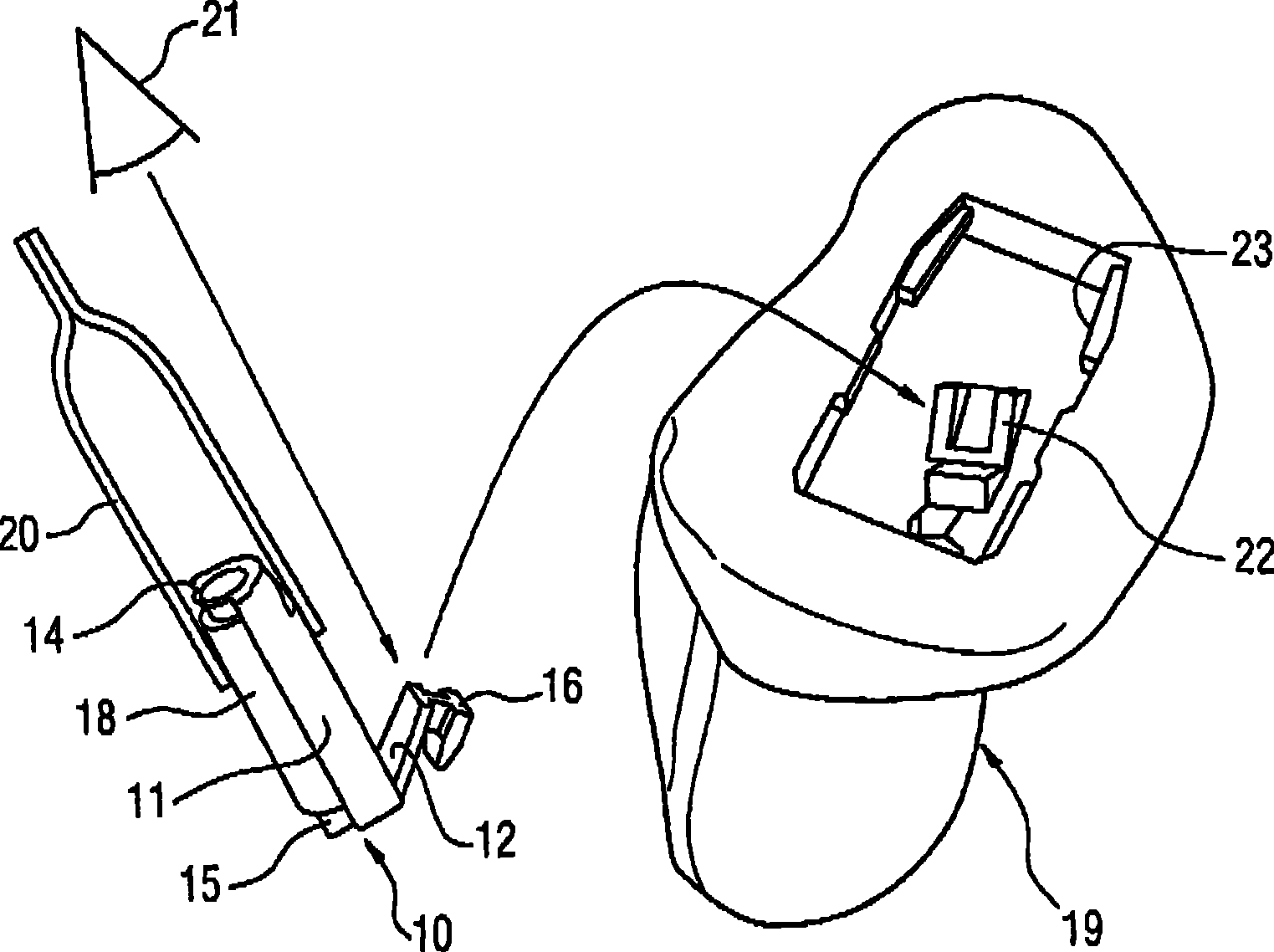
图4表现了借助于线圈保持器10将线圈18安装在IdO壳19内。线圈18压入到线圈保持器10的接合夹14和15内。线圈保持器10的两个臂处于在图2中所图示的V形位置。FIG. 4 represents the installation of the coil 18 in the IdO housing 19 by means of the coil holder 10 . The coil 18 is pressed into the engagement clips 14 and 15 of the coil holder 10 . The two arms of the coil holder 10 are in the V-shaped position illustrated in FIG. 2 .
为安装,安装者将线圈保持器10连同线圈18以镊子20夹持。眼睛21表示钩16在安装在助听器壳19中始终保持在安装者的视野内。因为钩16在安装中既不被安装工具20也不被线圈保持器10遮挡,它可以容易地插入到在助听器壳19的内壁内形成的轨道22内。由于钩16的这种可见性,也增加了线圈18可无需高昂成本即可固定在壳19内的位置的个数。特别地,线圈18可通过助听器壳内很小的孔23插入且接合部分保持可容易辨认。For mounting, the installer grips the coil holder 10 together with the coil 18 with tweezers 20 . The eye 21 means that the hook 16 always remains in the field of view of the wearer when installed in the hearing aid shell 19 . Since the hook 16 is neither covered by the installation tool 20 nor by the coil holder 10 during installation, it can easily be inserted into the rail 22 formed in the inner wall of the hearing aid shell 19 . Thanks to this visibility of the hooks 16, the number of positions at which the coil 18 can be fixed within the housing 19 is also increased without great expense. In particular, the coil 18 can be inserted through a very small hole 23 in the hearing aid shell and the engagement portion remains easily identifiable.
钩16在安装期间的可见性也是可容易地检查它在轨道22(例如SLA轨道)内的安放的基础。特别好的是识别钩16是否完全插入到轨道22内且以其尖端靠在对应的止动件上。总之可以保证线圈18的良好的安放,这得到了改进的产品质量。此外,将钩16插入到轨道22内可以很快速的进行,使得也给出了提高的安装速度。The visibility of the hook 16 during installation is also the basis for its easy inspection of its placement within the rail 22 (eg SLA rail). It is particularly advantageous to detect whether the hook 16 is completely inserted into the rail 22 and rests with its tip on the corresponding stop. Overall, a good placement of the coil 18 can be ensured, which leads to an improved product quality. Furthermore, the insertion of the hooks 16 into the rails 22 can be carried out very quickly, so that an increased installation speed is also given.
为附加的固定,可在将钩16引入到轨道22内之后在钩16上涂上一滴粘合剂。以此,粘合剂从上面固定钩。如果希望能将线圈18再次拆除,则有利的是使用可容易去除的粘合剂,例如硅胶。在将保持器安装在SLA轨道前涂粘合剂可能在拆除时导致问题。SLA轨道且因此整个SLA壳(SLA指立体光刻设备,stereo lithography apparatus)可能被毁坏。For additional fixation, a drop of adhesive can be applied to the hook 16 after it has been introduced into the rail 22 . In this way, the adhesive secures the hook from above. If it is desired to be able to remove the coil 18 again, it is advantageous to use an easily removable adhesive, such as silicone. Applying adhesive before installing the retainer on the SLA track may cause problems during removal. The SLA track and thus the entire SLA shell (SLA stands for stereolithography apparatus) may be destroyed.
现在借助于在安装中可见的钩16,将线圈保持器10可靠地引入到很小的轨道22内。作为最后的安装步骤,还必须将其上固定有线圈18的第一臂11压在第二臂12上。在此,臂11、12卡锁在对方内或上。安装者可以感受和/或感觉到此卡锁或扣接。最后,图5中给出了保持器10和线圈18在IdO壳19内的图示位置。此外,从图5中可认识到,线圈保持器10和线圈18如何布置在助听器壳19内的听筒24上方。因此对于线圈18,可实际上充分利用听筒24和向上限制了助听器壳19的内部空间的“盖”25之间的空间。这在图中表示为在线圈18或线圈保持器10的上边沿和盖25之间的间距为0mm。虽然具有此事实,但这种空间的充分利用可以通过这一事实实现,即,为了将钩16插入轨道22必需有大约1.5mm的移动行程。然而,其前提条件是根据本发明的线圈保持器10的折叠机构。The coil holder 10 is now reliably inserted into the small rail 22 by means of the hook 16 visible during installation. As a final mounting step, it is also necessary to press the first arm 11 , on which the coil 18 is fixed, onto the second arm 12 . Here, the arms 11 , 12 snap into or onto each other. The installer can feel and/or feel this snap or snap. Finally, a schematic position of the holder 10 and the coil 18 within the IdO housing 19 is given in FIG. 5 . Furthermore, it can be seen from FIG. 5 how the coil holder 10 and the coil 18 are arranged above the receiver 24 in the hearing aid shell 19 . The space between the earpiece 24 and the "cover" 25 which delimits the inner space of the hearing aid shell 19 upwards can thus be used to the full in practice for the coil 18 . This is shown in the figure as a distance of 0 mm between the upper edge of coil 18 or coil holder 10 and cover 25 . Notwithstanding this fact, this efficient use of space is achieved by the fact that in order to insert the hook 16 into the rail 22 a displacement travel of approximately 1.5 mm is necessary. A prerequisite for this, however, is the folding mechanism of the coil holder 10 according to the invention.
Claims (10)
Applications Claiming Priority (2)
| Application Number | Priority Date | Filing Date | Title |
|---|---|---|---|
| DE102006049470A DE102006049470B4 (en) | 2006-10-16 | 2006-10-16 | Hearing aid with a mounting device for a component of a hearing device and corresponding method |
| DE102006049470.9 | 2006-10-16 |
Publications (2)
| Publication Number | Publication Date |
|---|---|
| CN101166375A CN101166375A (en) | 2008-04-23 |
| CN101166375B true CN101166375B (en) | 2012-07-04 |
Family
ID=38948839
Family Applications (1)
| Application Number | Title | Priority Date | Filing Date |
|---|---|---|---|
| CN2007101802743A Expired - Fee Related CN101166375B (en) | 2006-10-16 | 2007-10-16 | Mounting device for a component in a hearing device and corresponding method |
Country Status (4)
| Country | Link |
|---|---|
| EP (1) | EP1915029B1 (en) |
| CN (1) | CN101166375B (en) |
| DE (1) | DE102006049470B4 (en) |
| DK (1) | DK1915029T3 (en) |
Families Citing this family (4)
| Publication number | Priority date | Publication date | Assignee | Title |
|---|---|---|---|---|
| WO2010117334A1 (en) * | 2009-04-06 | 2010-10-14 | Siemens Medical Instruments Pte Ltd | Hearing aid with insert |
| DE102009057581B4 (en) * | 2009-12-09 | 2016-01-07 | Sivantos Pte. Ltd. | hearing |
| DK2355552T3 (en) * | 2010-01-29 | 2013-02-18 | Oticon As | Hearing aid and handling tools |
| US20170064469A1 (en) * | 2015-08-31 | 2017-03-02 | Oticon A/S | Hearing device |
Citations (3)
| Publication number | Priority date | Publication date | Assignee | Title |
|---|---|---|---|---|
| CN1354966A (en) * | 1999-06-16 | 2002-06-19 | 福纳克有限公司 | Behind-the-ear hearing aid |
| CN1684548A (en) * | 2004-04-13 | 2005-10-19 | 西门子测听技术有限责任公司 | hearing aid |
| US7099485B2 (en) * | 2004-03-10 | 2006-08-29 | Phonak Ag | Housing for hearing devices or hearing aids |
Family Cites Families (3)
| Publication number | Priority date | Publication date | Assignee | Title |
|---|---|---|---|---|
| DE3601440A1 (en) * | 1986-01-20 | 1987-07-23 | Starkey Lab Germany Gmbh | Hearing aid to be worn in the ear |
| EP1435758A1 (en) * | 2004-01-16 | 2004-07-07 | Phonak Ag | Housing for a hearing prosthesis and a hearing aid |
| DE102004016573B3 (en) * | 2004-03-31 | 2005-11-03 | Siemens Audiologische Technik Gmbh | ITE hearing aid for the binaural care of a patient |
-
2006
- 2006-10-16 DE DE102006049470A patent/DE102006049470B4/en not_active Expired - Fee Related
-
2007
- 2007-09-26 DK DK07117261.3T patent/DK1915029T3/en active
- 2007-09-26 EP EP07117261A patent/EP1915029B1/en not_active Not-in-force
- 2007-10-16 CN CN2007101802743A patent/CN101166375B/en not_active Expired - Fee Related
Patent Citations (3)
| Publication number | Priority date | Publication date | Assignee | Title |
|---|---|---|---|---|
| CN1354966A (en) * | 1999-06-16 | 2002-06-19 | 福纳克有限公司 | Behind-the-ear hearing aid |
| US7099485B2 (en) * | 2004-03-10 | 2006-08-29 | Phonak Ag | Housing for hearing devices or hearing aids |
| CN1684548A (en) * | 2004-04-13 | 2005-10-19 | 西门子测听技术有限责任公司 | hearing aid |
Also Published As
| Publication number | Publication date |
|---|---|
| DE102006049470B4 (en) | 2011-06-22 |
| EP1915029A3 (en) | 2011-05-18 |
| EP1915029A2 (en) | 2008-04-23 |
| CN101166375A (en) | 2008-04-23 |
| DK1915029T3 (en) | 2012-10-15 |
| DE102006049470A1 (en) | 2008-07-31 |
| EP1915029B1 (en) | 2012-07-04 |
Similar Documents
| Publication | Publication Date | Title |
|---|---|---|
| US8437489B2 (en) | Hearing instrument | |
| US8718306B2 (en) | Hearing device with a detachably coupled earpiece | |
| EP1681904B1 (en) | Hearing instrument | |
| US20090252362A1 (en) | Hearing device to be carried in the auricle with an individual mold | |
| US8139800B2 (en) | Hearing apparatus with a magnetically attached battery holding device | |
| CN103379417B (en) | Hearing device with the connection of sound pipe connector | |
| CN102763434B (en) | Behind-the-ear hearing aids with connectors | |
| US9247360B2 (en) | Hearing instrument housing having a plug-in connection, plug and hearing instrument | |
| CN103875258B (en) | Method for manufacturing soft custom ear molds and soft custom ear molds | |
| US20140003638A1 (en) | Hybrid hearing instrument connector | |
| CN102404677A (en) | Connector for hearing aid, hearing aid and hearing aid system | |
| US20100208927A1 (en) | Microphone module for a hearing device | |
| US8103031B2 (en) | Hearing device sound emission tube with a 2-component design | |
| CN101166375B (en) | Mounting device for a component in a hearing device and corresponding method | |
| US8077895B2 (en) | Behind-the-ear hearing aid with audio shoe which can be pushed-on linearly, and appropriate mounting method | |
| CN104703109A (en) | HdO hearing aid worn behind the ear with housing and carrying hook | |
| US8374369B2 (en) | Assembly device for a component of a hearing apparatus and corresponding method | |
| US20080247581A1 (en) | Construction of A Completely-In-Canal Hearing Instrument With Receiver Compartment | |
| US20160037272A1 (en) | Microphone module latching configuration for a hearing instrument, microphone module and hearing instrument | |
| EP3435688A1 (en) | In the ear hearing aid with exposed electronic components | |
| US20090022348A1 (en) | Hearing apparatus with a fastening facility for attaching an audio shoe and corresponding audio shoe | |
| US10341788B2 (en) | Hearing aid battery drawer with a thin film | |
| US20080232626A1 (en) | Hearing apparatus with removable volume control module | |
| CN110505559B (en) | Earwax filter solution for hearing aid speakers | |
| CN103517167A (en) | Housing for a hearing instrument, and hearing instrument |
Legal Events
| Date | Code | Title | Description |
|---|---|---|---|
| C06 | Publication | ||
| PB01 | Publication | ||
| C10 | Entry into substantive examination | ||
| SE01 | Entry into force of request for substantive examination | ||
| C14 | Grant of patent or utility model | ||
| GR01 | Patent grant | ||
| C17 | Cessation of patent right | ||
| CF01 | Termination of patent right due to non-payment of annual fee |
Granted publication date: 20120704 Termination date: 20131016 |