CN1011390B - Automatic arc-welding method - Google Patents
Automatic arc-welding methodInfo
- Publication number
- CN1011390B CN1011390B CN88106124A CN88106124A CN1011390B CN 1011390 B CN1011390 B CN 1011390B CN 88106124 A CN88106124 A CN 88106124A CN 88106124 A CN88106124 A CN 88106124A CN 1011390 B CN1011390 B CN 1011390B
- Authority
- CN
- China
- Prior art keywords
- welding
- groove
- welding wire
- speed
- demarcation
- Prior art date
- Legal status (The legal status is an assumption and is not a legal conclusion. Google has not performed a legal analysis and makes no representation as to the accuracy of the status listed.)
- Expired
Links
Images


Classifications
-
- B—PERFORMING OPERATIONS; TRANSPORTING
- B23—MACHINE TOOLS; METAL-WORKING NOT OTHERWISE PROVIDED FOR
- B23K—SOLDERING OR UNSOLDERING; WELDING; CLADDING OR PLATING BY SOLDERING OR WELDING; CUTTING BY APPLYING HEAT LOCALLY, e.g. FLAME CUTTING; WORKING BY LASER BEAM
- B23K9/00—Arc welding or cutting
- B23K9/12—Automatic feeding or moving of electrodes or work for spot or seam welding or cutting
-
- B—PERFORMING OPERATIONS; TRANSPORTING
- B23—MACHINE TOOLS; METAL-WORKING NOT OTHERWISE PROVIDED FOR
- B23K—SOLDERING OR UNSOLDERING; WELDING; CLADDING OR PLATING BY SOLDERING OR WELDING; CUTTING BY APPLYING HEAT LOCALLY, e.g. FLAME CUTTING; WORKING BY LASER BEAM
- B23K9/00—Arc welding or cutting
- B23K9/095—Monitoring or automatic control of welding parameters
- B23K9/0953—Monitoring or automatic control of welding parameters using computing means
-
- B—PERFORMING OPERATIONS; TRANSPORTING
- B23—MACHINE TOOLS; METAL-WORKING NOT OTHERWISE PROVIDED FOR
- B23K—SOLDERING OR UNSOLDERING; WELDING; CLADDING OR PLATING BY SOLDERING OR WELDING; CUTTING BY APPLYING HEAT LOCALLY, e.g. FLAME CUTTING; WORKING BY LASER BEAM
- B23K9/00—Arc welding or cutting
- B23K9/06—Arrangements or circuits for starting the arc, e.g. by generating ignition voltage, or for stabilising the arc
- B23K9/073—Stabilising the arc
Landscapes
- Engineering & Computer Science (AREA)
- Physics & Mathematics (AREA)
- Plasma & Fusion (AREA)
- Mechanical Engineering (AREA)
- Theoretical Computer Science (AREA)
- Arc Welding In General (AREA)
- Butt Welding And Welding Of Specific Article (AREA)
Abstract
An automatic arc-welding method, which comprises: when welding two objects to be welded together by means of a welding wire along a first groove formed between the objects to be welded on a first side thereof, continuously determining by calculation a target welding current, with which a depth of penetration agrees with a target value thereof, on the basis of the root gap, the material of the welding wire and the like; continuously determining by calculation a target feeding rate of the welding wire, at which an extension length of the welding wire agrees with a target value thereof, on the basis of the welding current, the material of the welding wire and the like; continuously determining by calculation a target welding speed, on the basis of the feeding rate of the welding wire, the material of the welding wire and the like, thereby automatically controlling the welding current, the feeding rate of the welding wire and the welding speed on the basis of the respective target values thus determined.
Description
The present invention relates to a kind of automatic arc-welding method that utilizes welding wire as consumable electrode, when being particularly related to vertically the welding together of a kind of groove that between by this two articles, forms when two objects to be welded, even under the situation that the root spacing distance changes, also can prevent to burn the stable automatic arc-welding method of weld bead height that remains unchanged and electric arc.
When using welding wire as consumable electrode, with two objects to be welded along by the groove that forms between this two articles vertically with arc welding together the time, common welding is to serve as zero to realize with the root gap of groove distance, that is to say that its root face keeps in touch each other.Particularly when carrying out automatic arc welding and connect, the common distance of controlling root gap so that the maximum of root gap distance remains on 1mm strictly.The root gap of big distance can cause incomplete fusion penetration and burn.Yet in fact owing to the restriction of machining accuracy, the variation of the root gap distance on the longitudinal direction of groove is inevitable.
Therefore, traditional mode is before object to be welded is welded together along a groove, in advance on the whole length of groove, utilize and to fill bigger root gap part in allowed limits, with the distance of change root gap as the mode of manual welding.In addition, increase the height of root face so that do not cause that or not also is necessary burning.
Yet, before extensive welding, fill the efficient that root gap can cause reducing on the whole welding operation with such manual operations.In addition, as mentioned above, the also essential width of root face that increases groove.The result, when from first of object to be welded and second twice welding, in first groove welding back that forms on first, before second groove that forms on second welds, fusion penetration for satisfaction guaranted, essential finishing second groove (as adopting the mode of cutter) is until the bottom surface of second groove arrives till the weld seam that forms in first groove.
The Chinese patent application that on August 6th, 1986 published discloses a kind of one-sided arc welding object to be welded, forms the method for gratifying root pass at the back side of object to be welded.This method comprises following all steps.
By a metal backing, inorganic flux is closely contacted, with the described object to be welded back side along the groove between the object to be welded, only with their arc weldings together from the front of described object to be welded.
In the process of the described object to be welded of arc welding, utilize signal generator that the signal of telecommunication is added between described object to be welded and the described metal backing, signal generator has the frequency that is different from the source of welding current, electric current, voltage and other electrical characteristic are added in voltage signal and/or current signal between described object to be welded and the described metal backing so that detect from what described signal generator sent; And
According to the detected signal of telecommunication like this and/or current signal, control comprises welding current, weldingvoltage, speed of welding and electrode extension be in interior welding parameter, thereby form gratifying root pass (hereinafter being referred to as prior art) at the object to be welded back side.
According to this prior art, no matter along groove longitudinally the distance of root gap how to change, by controlling such as weldingvoltage, welding current, speed of welding, and electrode extension, make the voltage signal and/or the current signal that are added between object to be welded and the metal backing that send from signal generator keep invariable, just can form gratifying root pass at the back side of object to be welded with even constant width.
, in this prior art, do not measure the distance of the groove root gap in welding wire moving direction downstream.In addition, this prior art is not considered following various relations:
(a) between the distance of root gap and the welding current for the relation of fusion penetration,
(b) between the feed rate of welding wire and the weldering stream electric current for the relation of electrode extension, and
(c) extension elongation of welding wire, the feed rate of welding wire, between weldingvoltage and the welding current for the relation of arc length.Therefore, according to this prior art, guarantee needed fusion penetration respectively, needed electrode extension and needed fusion penetration, needed electrode extension and needed arc length and accurately control welding current, the feed rate of welding wire and weldingvoltage are inconvenient.
In this case, just need a kind of automatic arc-welding method of research, this method even also can guarantee constant fusion penetration under apart from situation about changing at vertical root gap of groove can prevent to burn, keep constant weld bead height and stable electric arc under the situation that does not increase the width of root face.But so a kind of automatic arc-welding method never puts forward.
Therefore, the object of the present invention is to provide a kind of automatic arc-welding method, this method in addition at the root gap of the longitudinal direction of groove when changing, also constant fusion penetration be can guarantee, constant weld bead height and stable electric arc under the situation that does not increase the width of root face, can be prevented to burn, keep.
One of feature of the present invention has provided a kind of automatic arc-welding method, and this method comprises:
As consumable electrode, with the feed rate of regulation welding wire is offered between by two objects to be welded first on formed first groove continuously, this welding wire is to provide towards first groove by nozzle with vertical direction substantially with welding wire; With described nozzle together with described welding wire along described first groove vertically constantly the operation; The welding current of regulation is offered welding wire, so that produce electric arc between the end of described welding wire and described first groove, thus utilize this arc heat that described object to be welded is welded together along the speed of welding of described first groove with regulation; Then, make welding wire substantially vertically by described nozzle with the feed rate of stipulating, constantly provide towards formed second groove on second of described object to be welded, described second groove is relative with described first groove; With described nozzle together with described welding wire along described second groove vertically constantly the operation; The welding current of regulation is offered described welding wire, so that produce electric arc between the end of described welding wire and described second groove, thus utilize this arc heat that described object to be welded is welded together along the speed of welding of described second groove with regulation.
This improved being characterised in that:
(A) when with described object to be welded when described first groove welding is connected together,
(a). constantly measure the distance of root gap at the traffic direction of this nozzle of lower end edge of described nozzle;
(b). calculate demarcation welding current (I) according to following formula (1), under this electric current, fusion penetration is consistent with its calibration value:
I=Io-KG……(1)
Here I: demarcate welding current,
Io: the welding current when the root gap distance is zero,
K: visual fusion is dark, kind of protective gas, solder wire material or the like and fixed coefficient,
G: the distance of root gap,
Control described welding current, so that make it consistent with the demarcation welding current that calculates,
(c). calculate the demarcation feed rate (V of described welding wire according to following formula (2)
f), under this feed rate, described welding wire is consistent with its calibration value from the extension elongation of the ignition tip of described nozzle:
V
f=A·I+B·L·I
2……(2)
Here V
f: the demarcation feed rate of welding wire,
I: welding current,
L: the extension elongation of welding wire,
A, B: the coefficient of deciding on the kind of protective gas, solder wire material or the like,
The described feed rate of control welding wire is so that make its demarcation feed rate with the welding wire that calculates consistent;
(d). calculate demarcation speed of welding (V) according to following formula (3), under this speed of welding, the height of weld seam is consistent with its calibration value:
V=V
f(V
fo/V
o+ (d)/(K) ·G)……(3)
Here V: demarcate speed of welding,
V
f: the feed rate of welding wire,
V
Fo: the advancing of welding wire when root gap distance is zero for speed,
V
o: the speed of welding when the root gap distance is zero,
D: the distance between the minimum point of fusion penetration and the peak of weld seam,
K: the cross-sectional area of welding wire and the product of deposition efficiency,
G: the distance of root gap,
Control described speed of welding, so that make it consistent with the demarcation speed of welding that calculates.
(B). when with described object to be welded when described second groove welding is connected together,
(a). constantly measure the distance of root gap at the traffic direction of this nozzle of lower end edge of described nozzle;
(b). calculate the demarcation welding current according to described formula (1), under this electric current, when described root gap distance is zero, demarcate fusion penetration (P
2) meet following formula (4):
P
2≥t
f-P
1……(4)
Here P
2: the demarcation fusion penetration of second groove,
P
1: the demarcation fusion penetration of first groove,
t
f: the height of root face,
Control described welding current, so that make it consistent with the demarcation welding current that calculates;
(c). calculate demarcation speed of welding (V) according to following formula (5), the height of weld seam is consistent with its calibration value under this speed:
V=V
fo(V
fo/V
o+ (d)/(K) ·G)……(5)
Here V: demarcate speed of welding,
V
Fo: the feed rate of welding wire when the root gap distance is zero,
V
o: the speed of welding when the root gap distance is zero,
D: the distance between the minimum point of fusion penetration and the peak of weld seam,
K: the cross-sectional area of welding wire and the product between the deposition efficiency,
G: the distance of root gap,
Control described speed of welding, so that make it consistent with the demarcation speed of welding that calculates.
Fig. 1 is the block diagram of an embodiment of automatic arc-welding method of the present invention;
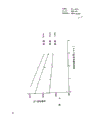
The figure of Fig. 2 for concerning between the root gap of groove distance and the welding current, with fusion penetration as parameter;
Fig. 3 is the cross-sectional view of typical two groove examples
The figure that concerns between feed rate, weldingvoltage and the speed of welding of Fig. 4 for expression welding current, welding wire.
From above-mentioned viewpoint, conduct extensive research for improving a kind of automatic arc-welding method, this Innovative method is also can guarantee constant fusion penetration at vertical root gap of groove in apart from situation about changing, and can prevent the stable of the weld bead height of burning, remaining unchanged and electric arc when not increasing the width of root face. Therefore, draw following result of study:
(1) if. exist certain relation with respect to fusion penetration between welding current and root gap distance, by measuring the root gap distance of groove, the demarcation welding current when determining that by calculating fusion penetration is consistent with its calibration value is possible so.
(2) if. the height with respect to weld seam between the feed rate of welding current, speed of welding, welding wire and root gap distance exists certain relation, so under above-mentioned Calibrated current, be possible by calculating the demarcation speed of welding of the height of determining weld seam when consistent with its calibration value.
(3) if. the extension elongation with respect to welding wire between the feed rate of welding current and welding wire exists certain relation, so under above-mentioned demarcation welding current, by The demarcation feed rate of calculating determine the welding wire when consistent with its calibration value from the length of the welding wire of the ignition tip of nozzle is possible.
The present invention is based on above-mentioned result of study and produces.Now, at length narrate automatic arc-welding method of the present invention with reference to the accompanying drawings.
Fig. 1 is the block diagram of an embodiment of automatic arc-welding method of the present invention.
As shown in Figure 1, two object 1A to be welded and 1B are along being welded together by first groove 2 that forms between this two articles and second groove 3.First groove 2 is to form on first face of object 1A to be welded and 1B, and second groove 3 is to form on second face of object 1A to be welded and 1B, and second groove 3 is relative with first groove 2.
Nozzle 4 is driven by conveyer 5 and moves continuously along first groove 2 or second groove 3.The speed of service of this conveyer, just speed of welding is controlled by the 3rd controller 6, so that make the height of weld seam consistent with its calibration value, such just as will be described.This nozzle 4 rotates to center on its central shaft at a high speed along the direction shown in the sequence number A among Fig. 1.
Welding wire 7 and nozzle center eccentric shaft ground as consumable electrode insert in this nozzle 4, and welding wire 7 continuously feeds to first groove 2 or second groove 3 with the vertical direction of cardinal principle by nozzle 4 by wire feed unit 8.The feed rate of the welding wire that is provided by welding wire feeder 8 is controlled by second controller 9, so that make the extension elongation of the welding wire that the ignition tip by nozzle rises consistent with its calibration value.
For the consistent required welding current of fusion penetration with its calibration value, as the back to illustrate, it is provided between object 1A to be welded and 1B and the welding wire 7 by the source of welding current 11 that controlled by first controller 10, thereby between the end of welding wire 7 and first groove 2 or second groove 3, produce electric arc, utilize this arc heat that object 1A to be welded and 1B are welded together along first groove 2 or second groove 3.First groove 2 or the utilization of second groove 3 are arranged near the emitted protective gas protection of a nozzle (not shown) the ignition tip of nozzle 4 and are not subjected to the influence of atmosphere.There is no need to be pointed out that application of the present invention is not limited to above-mentioned known rotating the arc welding method.
The signal that image processor 13 sends along with TV camera 12 is constantly measured first groove 2 or second groove 3, in the computer that will illustrate below the data of measured root gap distance are input to.
The result of calculation that computer 14 will illustrate the back offers first controller 10, second controller 9 and the 3rd controller 6.When with object 1A to be welded and 1B when first groove 2 welds together, the formula (1) to (3) that uses below given being input to earlier in the computer 14:
I=I
o-KG……(1)
Above-mentioned formula (1) is used for calculating demarcates welding current (I), and under this electric current, fusion penetration is consistent with its calibration value, in formula (1),
I: demarcate welding current,
I
o: the welding current when the root gap distance is zero,
K: visual fusion is dark, kind of protective gas, the material of welding wire or the like and fixed coefficient,
G: the distance of root gap,
The result of calculation that computer 14 will be demarcated welding current offers first controller 10.Above-mentioned I
oBe input in the computer 14 by input unit 15 in advance with K.
The figure of Fig. 2 for concerning between expression root gap distance of groove and the welding current, and with fusion penetration as parameter.More precisely, the figure of Fig. 2 clearly show that the actual range of measured root gap and finishes certain relation existing between the actual welding electric current that fusion penetration is respectively 1mm, 2mm, 3mm, sets up so proved above-mentioned formula (1).
V
f=A·I+B·L·I
2……(2)
Above-mentioned formula (2) is used to calculate the demarcation feed rate V of welding wire
f, welding wire is consistent with its calibration value from the extension elongation of the ignition tip of nozzle 4 under this speed.In formula (2):
V
f: the demarcation feed rate of welding wire,
I: welding current,
L: the extension elongation of welding wire,
A, B: the coefficient of deciding on the kind of protective gas, material of welding wire or the like,
Above-mentioned " L ", " A " and " B " import computers 14 by input unit 15 in advance.
Computer 14 offers second controller 9 with the result of calculation of the demarcation feed rate of welding wire, and the control of welding wire feeding speed should make the extension elongation of welding wire consistent with its calibration value, to guarantee the stable of electric arc.
Fig. 4 shows the relation between feed rate, weldingvoltage and the speed of welding of welding current, welding wire.In Fig. 4, the line of feed rate of expression welding wire clearly show that the certain relation that exists between the welding wire feeding speed of used actual welding electric current and used reality, so has proved that formula (2) sets up.
V=V
f(V
fo/V
o+ (d)/(K) ·G)……(3)
Above-mentioned formula (3) is used for calculating demarcates speed of welding (V), and the height of weld seam is consistent with its calibration value under this speed.In formula (3):
V: demarcate welding current,
V
f: the feed rate of welding wire,
V
Fo: the feed rate of welding wire when the root gap distance is zero,
V
o: the speed of welding when the root gap distance is zero,
D: the distance between the minimum point of fusion penetration and the peak of weld seam,
K: the cross-sectional area of welding wire and the product of deposition efficiency,
G: the distance of root gap,
The result of calculation that computer 14 will be demarcated speed of welding offers the 3rd controller 6.Above-mentioned V
Fo, V
o, d and K be input in the computer 14 by input unit 15 in advance.
In Fig. 4, the line of expression speed of welding clearly show that existing certain relation between used actual welding electric current and the used actual welding speed, so has proved that formula (3) sets up.
In addition, when two object 1A to be welded and 1B when second groove 3 welds together, formula (4) and (5) of using below are input in the computer 14 in advance:
P
2≥t
f-P
1……(4)
Here P
2: the demarcation fusion penetration of second groove,
P
1: the demarcation fusion penetration of first groove,
t
f: the height of root face,
Computer 14 calculates according to above-mentioned formula (1) and demarcates welding current.Demarcate under the welding current at this, it demarcates fusion penetration (P when the root gap distance is zero
2) be corresponding to above-mentioned formula (4).Supposing that the root gap distance is zero, is because when welding second groove 3, this root gap is filled up by the welding of first groove 2, thereby the danger that can not burn.The result of calculation that computer 14 will be demarcated welding current offers first controller 10.Above-mentioned P
1, P
2And t
fBe input in the computer 14 by input unit 15 in advance.
V=V
fo(V
fo/V
o+ (d)/(K) ·G)……(5)
Above-mentioned formula (5) is used for calculating demarcates speed of welding (V), and the height of weld seam is consistent with its calibration value under this speed.In formula (5):
V: demarcate speed of welding,
V
Fo: the feed rate of welding wire when the root gap distance is zero,
V
o: the speed of welding when the root gap distance is zero,
D: the distance between the minimum point of fusion penetration and the peak of weld seam,
K:: the cross-sectional area of welding wire and the product between the deposition efficiency,
G: the distance of root gap.
The result of calculation that computer 14 will be demarcated speed of welding offers the 3rd controller 6.When welding second groove 3, because the demarcation welding current that is calculated by above-mentioned formula (1) is a constant, so do not need to control the feed rate of welding wire.
Preferably weldingvoltage is controlled, so that stable arc further.For this reason, following formula (6) is input in the computer 14 in advance:
Et=EL+Ea+Er……(6)
Top formula (6) is used for calculating demarcates weldingvoltage (Et), consistent with its calibration value in this length of demarcating electric arc under the weldingvoltage.In formula (6):
Et: demarcate weldingvoltage,
EL: the voltage drop that causes by the extension elongation of welding wire,
Ea: arc voltage,
Er: the voltage drop that causes because of the summation of another output of an output of the source of welding current and the resistance between the nozzle and the source of welding current and the resistance between the welded piece.
Above-mentioned EL, Ea and Er are represented by following formula (7) to (9) respectively:
EL=a·L·I-b·V
f/I……(7)
Ea=E
0(I)+X·La……(8)
Er=R·I……(9)
Here l: the extension elongation of welding wire,
I: welding current,
V
f: the feed rate of welding wire,
Ab: the coefficient of deciding on the kind of protective gas, material of welding wire or the like,
E
0(I): equal the voltage drop that summation falls in negative electricity pressure drop and cathode voltage,
X: the potential gradient of arc column,
La: arc length,
R a: output of the source of welding current and the other end of the resistance between the nozzle and the source of welding current and the summation of the resistance between the welded piece.
The result of calculation that computer 14 will be demarcated weldingvoltage offers first controller 10.
In Fig. 4, the line of expression weldingvoltage clearly show that certain relation existing between actual used welding current and the actual used weldingvoltage, so has proved that formula (6) sets up.
Situation about object 1A to be welded and 1B being welded together along first groove 2 according to method of the present invention is described now.
When nozzle 4 with at a high speed round its central shaft rotation the time, nozzle 4 constantly moves along first groove 2 by means of the effect of conveyer 5.Welding current is fed on the welding wire 7 that inserts this nozzle 4 by the source of welding current 11, the source of welding current 11 is controlled by first controller 10, thereby between the end of welding wire 7 and first groove 2, produce electric arc, utilize the heat of this electric arc that object 1A to be welded and 1B are welded together along first groove 2.
Computer 14 calculates the demarcation feed rate (V of welding wire according to the formula (2) of above-mentioned input in advance
f), with this feed rate, under the condition of the above-mentioned demarcation welding current that calculates, the extension elongation of the welding wire that is risen by the ignition tip of nozzle 4 is consistent with its calibration value.Computer 14 offers second controller 9 with the result of calculation of the demarcation feed rate of welding wire.These second controller, 9 control welding wire feeders 8, so that make welding wire 7 to be provided to continuously in first groove 2 with the corresponding to welding wire feeding speed of the above-mentioned demarcation feed rate that is calculated, thereby make the extension elongation of welding wire always consistent with its calibration value, and need not consider whether welding current has any variation, therefore guaranteed the stable of electric arc.
Computer 14 calculates demarcation speed of welding (V) according to the formula (3) of above-mentioned input in advance, and with this speed of welding, under the condition of the above-mentioned welding current that calculates, the height of weld seam 16 is consistent with its calibration value.The result of calculation that computer 14 will be demarcated speed of welding offers the 3rd controller 6.The 3rd controller 6 control conveyers 5; So that make object 1A to be welded and 1B to weld together along first groove 2 with the above-mentioned corresponding to speed of welding of demarcation speed of welding that is calculated, thereby the height of weld seam 16 is always consistent with its calibration value, and need not consider whether root gap distance (G) has any variation.
Situation about object 1A to be welded and 1B being welded together along second groove 3 according to method of the present invention is described now.
When nozzle 4 with at a high speed round its axis rotation the time, this nozzle moves along second groove 3 continuously by means of the effect of conveyer 5.Welding current is fed on the welding wire 7 that inserts this nozzle 4 by the source of welding current 11, this source of welding current 11 is controlled by first controller 10, thereby between the end of welding wire 7 and second groove 3, produce electric arc, utilize the heat of this electric arc that object 1A to be welded and 1B are welded together along second groove 3.
Computer 14 calculates demarcation speed of welding (V) according to the formula (5) of above-mentioned input in advance, welds with this speed of welding, and under the condition of the above-mentioned demarcation welding current that calculates, the height of weld seam 16 is consistent with its calibration value.The result of calculation that computer 14 will be demarcated speed of welding offers the 3rd controller 6.These controller 6 control conveyers 5, so that object 1A to be welded is welded together with the speed of welding consistent with the above-mentioned demarcation speed of welding that is calculated along second groove 3 with 1B, thereby the height of weld seam 16 is always consistent with its calibration value, and need not consider whether the root gap distance has any variation.
An example of automatic arc-welding method of the present invention is described now.
With thickness is that two corrosion resistant plates (SUS304) of 10mm are as object 1A to be welded and 1B.As shown in Figure 3, a kind of first groove 2 of shape and second groove 3 form between two plates.Use automatic arc welding machine as shown in Figure 1 to weld together object 1A to be welded and 1B then along first groove 2 and second groove 3.With diameter is that the flux-cored wire of 1.6mm is made welding wire, uses CO
2Gas is as protective gas.
At first, when will be when first groove 2 welds together, following data be given being input to earlier in the computer 14 with object 1A to be welded and 1B:
Calculating for demarcation welding current (I):
P
1:2mm
I
o:360A,
K:37,
Here P
1: the demarcation fusion penetration of first groove,
I
o: the welding current when the root gap distance is zero
K: visual fusion is dark, kind of protective gas, the material of welding wire or the like and fixed coefficient.
Demarcation feed rate (V for welding wire
f) calculating:
L:15mm
A:0.2,
B:4.59×10
-5
Here L: the extension elongation of welding wire
A, B: the coefficient of deciding on the kind of protective gas, material of welding wire or the like, for the calculating of demarcating speed of welding (V):
V
Fo: 161mm/ second
V
o: 8.3mm/ second
d:6.5mm
K:1mm
2
Here .V
Fo: the feed rate of welding wire when the root gap distance is zero
V
o: the speed of welding when the root gap distance is zero
D: the distance between the minimum point of fusion penetration and the peak of weld seam
K: the cross-sectional area of welding wire and the product between the deposition efficiency.
Then, when will with welded article body 1A and 1B when second groove 3 welds together, following data in advance being input in the computer 14:
P
2:2mm,
P
1:2mm,
t
f:3mm
V
Fo: 161mm/ second,
V
o: 8.3mm/ second,
d:6.5mm
K:1mm
2
Here P
2: the demarcation fusion penetration of second groove
P
1: the demarcation fusion penetration of first groove
t
f: the height of root face
V
Fo: the feed rate of welding wire when the root gap distance is zero
V
o: the speed of welding when the root gap distance is zero
D: the distance between the minimum point of fusion penetration and the peak of weld seam
K: the cross-sectional area of welding wire and the product between the deposition efficiency.
Resemble in this wise the height of research weld seam on welded article body 1A that welds together along first groove 2 and second groove 3 and 1B, its result shows, no matter how root gap distance (G) changes, weld bead height 16 is constant, fusion penetration on first groove 2 and second groove 3 is consistent with its calibration value respectively, therefore can obtain satisfactory flawless weld seam.
As mentioned above, according to the present invention, do not need to consider that any change of root gap distance is to obtain constant fusion penetration, thereby weld bead height that can prevent to burn, keep constant and electric arc is stable under the situation that does not increase the width of root face, therefore has a practical function industrial.
Claims (1)
1, a kind of automatic arc-welding method, comprising: as consumable electrode, with the feed rate of regulation welding wire is offered between by two objects to be welded first on formed first groove continuously, this welding wire is to provide towards described first groove by nozzle with vertical direction substantially with welding wire; With described nozzle together with described welding wire along described first groove vertically constantly the operation; The welding current of regulation is offered welding wire, so that produce electric arc between the end of described welding wire and described first groove, thereby utilize the heat of this electric arc that described object to be welded is welded together then along the speed of welding of described first groove with regulation, feed rate with regulation makes welding wire substantially vertically by described nozzle, constantly provide towards second groove that forms on second of described object to be welded, described second groove is relative with described first groove; With described nozzle together with described welding wire along described second groove vertically constantly the operation; The welding current of regulation is offered described welding wire, so that produce electric arc between the end of described welding wire and described second groove, thus utilize this arc heat that described object to be welded is welded together along the speed of welding of described second groove with regulation,
It is characterized in that:
(A). when with described object to be welded when described first groove welding is connected together,
(a). constantly measure the distance of root gap at the traffic direction of this nozzle of lower end edge of described nozzle;
(b). calculate demarcation welding current (I) according to following formula (1), under this electric current, fusion penetration is consistent with its calibration value:
Ⅰ=Ⅰ
0-KG…………(1)
Here I: demarcate welding current,
I
0: the welding current when the root gap distance is zero
K: visual fusion is dark, kind of protective gas, solder wire material or the like and fixed coefficient,
G: the distance of root gap,
Control described welding current, so that make it consistent with the demarcation welding current that calculates;
(C), calculate the demarcation feed rate (V of described welding wire according to following formula (2)
f), under this feed rate, described welding wire is consistent with its calibration value from the extension elongation of the ignition tip of described nozzle:
V
f=A·I+B·L·I
2……(2)
Here V
f: the demarcation feed rate of welding wire,
I: welding current,
L: the extension elongation of welding wire,
A, B: the coefficient of deciding on the kind of protective gas, solder wire material or the like,
The described feed rate of control welding wire is so that make its demarcation feed rate with the welding wire that calculates consistent;
(d), calculate to demarcate speed of welding (V), under this speed of welding, the height of weld seam is consistent with its calibration value according to following formula (3):
V=V
f(V
fo/V
o+ (d)/(k) ·G)……(3)
Here V: demarcate speed of welding,
V
f: the feed rate of welding wire,
V
Fo: the feed rate of welding wire when the root gap distance is zero,
V
o: the speed of welding when the root gap distance is zero,
D: the distance between the minimum point of fusion penetration and the peak of weld seam,
K: the cross-sectional area of welding wire and the product of deposition efficiency,
G: the distance of root gap,
Control described speed of welding, so that make it consistent with the demarcation speed of welding that calculates.
(B), when with described object to be welded when described second groove welding is connected together,
(a). constantly measure the distance of root gap at the traffic direction of this nozzle of lower end edge of described nozzle;
(b). calculate the demarcation welding current according to described formula (1), under this electric current, when described root gap distance is zero, target fusion penetration (P
2) meet following formula (4):
P
2≥t
f-P
1……(4)
Here P
2: the demarcation fusion penetration of second groove,
p
1: the demarcation fusion penetration of first groove,
t
f: the height of root face.
Control described welding current, so that make it consistent with the demarcation welding current that calculates;
(C). calculate demarcation speed of welding (V) according to following formula (5), the height of weld seam is consistent with its calibration value under this speed:
V=V
fo(V
fo/V
o+ (d)/(k) ·G)……(5)
Here V: demarcate speed of welding,
V
Fo: the feed rate of welding wire when the root gap distance is zero,
V
o: the speed of welding when the root gap distance is zero,
D: the distance between the minimum point of fusion penetration and the peak of weld seam,
K: the cross-sectional area of welding wire and the product between the deposition efficiency,
G: the distance of root gap,
Control described speed of welding, so that make it consistent with the demarcation speed of welding that calculates.
Applications Claiming Priority (2)
| Application Number | Priority Date | Filing Date | Title |
|---|---|---|---|
| JP180359/87 | 1987-07-20 | ||
| JP62180359A JPS6422469A (en) | 1987-07-20 | 1987-07-20 | Automatic arc welding method |
Publications (2)
| Publication Number | Publication Date |
|---|---|
| CN1031343A CN1031343A (en) | 1989-03-01 |
| CN1011390B true CN1011390B (en) | 1991-01-30 |
Family
ID=16081867
Family Applications (1)
| Application Number | Title | Priority Date | Filing Date |
|---|---|---|---|
| CN88106124A Expired CN1011390B (en) | 1987-07-20 | 1988-07-20 | Automatic arc-welding method |
Country Status (7)
| Country | Link |
|---|---|
| US (1) | US4816640A (en) |
| EP (1) | EP0300369B1 (en) |
| JP (1) | JPS6422469A (en) |
| KR (1) | KR920004265B1 (en) |
| CN (1) | CN1011390B (en) |
| CA (1) | CA1302515C (en) |
| DE (1) | DE3875413T2 (en) |
Families Citing this family (17)
| Publication number | Priority date | Publication date | Assignee | Title |
|---|---|---|---|---|
| US4920249A (en) * | 1989-05-08 | 1990-04-24 | General Electric Company | Weld bead wetting angle detection and control |
| CN1043018C (en) * | 1993-02-04 | 1999-04-21 | 新日本制铁株式会社 | Welding deformation reducing method for one-side strap joint welding |
| IT1266840B1 (en) * | 1994-05-26 | 1997-01-21 | P W T S P A | AUTOMATIC CONTROL SYSTEM OF THE METHODS OF DEPOSIT AND ADDING OF THE WELDING MATERIAL IN THE ORBITAL WELDING PROCESSES |
| JPH09277045A (en) * | 1996-04-12 | 1997-10-28 | Fanuc Ltd | Control method in multi-layer welding |
| US20020088778A1 (en) * | 1996-10-28 | 2002-07-11 | Lasertech Usa, Llc | Apparatus and method for laser welding bellows based on reference point determining |
| JP5214859B2 (en) | 2005-11-07 | 2013-06-19 | 株式会社ダイヘン | Output control method for consumable electrode arc welding power supply |
| EP2093009B1 (en) * | 2006-10-19 | 2016-08-31 | Panasonic Intellectual Property Management Co., Ltd. | Method for controlling arc welding and arc welding apparatus |
| JP4494450B2 (en) * | 2007-10-19 | 2010-06-30 | 富士フイルム株式会社 | Image processing apparatus, image processing method, and program |
| JP5001817B2 (en) * | 2007-12-21 | 2012-08-15 | 株式会社ダイヘン | Stitch pulse welding method |
| DE102008032509A1 (en) * | 2008-07-10 | 2010-01-14 | Epcos Ag | Heating device and method for producing the heating device |
| EP2436472B1 (en) * | 2009-05-27 | 2023-02-01 | JFE Steel Corporation | Submerged arc welding method for steel plate |
| US20130119040A1 (en) * | 2011-11-11 | 2013-05-16 | Lincoln Global, Inc. | System and method for adaptive fill welding using image capture |
| US10046410B2 (en) * | 2012-07-19 | 2018-08-14 | Lincoln Global Inc. | Apparatus and method for modulating heat input during welding |
| KR101473639B1 (en) * | 2013-02-25 | 2014-12-17 | 대우조선해양 주식회사 | Large volume butt joint welding apparatus and the method thereof |
| JP6619300B2 (en) * | 2016-07-27 | 2019-12-11 | 株式会社神戸製鋼所 | Welding equipment |
| CN107570897A (en) * | 2017-08-30 | 2018-01-12 | 佛山市宏石激光技术有限公司 | A kind of wire filling laser welding wire feed rate control method, apparatus and system |
| CN108705177A (en) * | 2018-05-30 | 2018-10-26 | 金立秋 | A kind of automatic continuous welding method of welding rod |
Family Cites Families (4)
| Publication number | Priority date | Publication date | Assignee | Title |
|---|---|---|---|---|
| US4532404A (en) * | 1983-02-01 | 1985-07-30 | Canadian Patents And Development Limited | Real time control system and process for controlling predetermined operating characteristics of a welding mechanism |
| DD221665A1 (en) * | 1984-03-09 | 1985-05-02 | Zentralinstitut Schweiss | METHOD FOR MONITORING AND CONTROLLING THE WELDING PROCESS |
| US4591689A (en) * | 1985-02-25 | 1986-05-27 | Caterpillar Tractor Co. | Adaptive welding guidance apparatus |
| US4733051A (en) * | 1987-08-25 | 1988-03-22 | Canadian Patents And Development Limited | Method and apparatus for controlling root pass weld penetration in open butt joints |
-
1987
- 1987-07-20 JP JP62180359A patent/JPS6422469A/en active Granted
-
1988
- 1988-07-14 US US07/219,391 patent/US4816640A/en not_active Expired - Lifetime
- 1988-07-14 EP EP88111343A patent/EP0300369B1/en not_active Expired - Lifetime
- 1988-07-14 DE DE8888111343T patent/DE3875413T2/en not_active Expired - Fee Related
- 1988-07-15 CA CA000572150A patent/CA1302515C/en not_active Expired - Lifetime
- 1988-07-19 KR KR1019880009016A patent/KR920004265B1/en not_active IP Right Cessation
- 1988-07-20 CN CN88106124A patent/CN1011390B/en not_active Expired
Also Published As
| Publication number | Publication date |
|---|---|
| EP0300369A2 (en) | 1989-01-25 |
| CN1031343A (en) | 1989-03-01 |
| KR920004265B1 (en) | 1992-06-01 |
| DE3875413T2 (en) | 1993-03-25 |
| EP0300369A3 (en) | 1989-04-19 |
| JPH0450102B2 (en) | 1992-08-13 |
| EP0300369B1 (en) | 1992-10-21 |
| JPS6422469A (en) | 1989-01-25 |
| DE3875413D1 (en) | 1992-11-26 |
| US4816640A (en) | 1989-03-28 |
| KR890001678A (en) | 1989-03-28 |
| CA1302515C (en) | 1992-06-02 |
Similar Documents
| Publication | Publication Date | Title |
|---|---|---|
| CN1011390B (en) | Automatic arc-welding method | |
| CN1012479B (en) | Method of automatic electric arc welding | |
| CN101032778A (en) | Pulsed arc welding method | |
| CN1101292C (en) | Automatic assemblying system of galvanized steel sheet by spot welding | |
| CN1250369C (en) | Automatic welding device and wldking skill training device | |
| CN100337781C (en) | Material for welding and welded article | |
| CN1247355C (en) | Welding method, welding device, welded joint and welded structure | |
| CN1203955C (en) | Constructive body and friction strir welding method | |
| CN1810437A (en) | Electrode for resistance welding, method for resistance welding and welding structure | |
| CN1819958A (en) | Image forming apparatus | |
| CN1704195A (en) | Controller for a wire electrical discharge machine | |
| CN1608787A (en) | Method for laser welding steel sheets and composite material | |
| CN1231323C (en) | Double-electrode signle gas protective arc welding method and device | |
| CN1503711A (en) | Friction agitation joining method, method for manufacturing joined butted members and friction agitation joining apparatus | |
| CN86106356A (en) | The belt carcass tubular pole and the method that are used for electric-arc cutting of metals | |
| CN1946506A (en) | Joined body of different materials of steel material and aluminum material and method for joining the same | |
| CN1019174B (en) | Automatic arc-welding method | |
| CN1479390A (en) | Manufacturing method of closed cell and closed cell | |
| CN1265515C (en) | Welding equipment | |
| CN1776416A (en) | Gas sensor unit and sensor cap | |
| CN1170940A (en) | Resistor and its producing method | |
| CN1080186C (en) | Improvement to butt-welding process | |
| CN1165065A (en) | Welding power control apparatus for consumable-electrode type pulse arc welding, and method therefor | |
| CN1235713C (en) | Single-side welding apparatus and method for bent plate | |
| CN1976777A (en) | Fastening member for press-fit joining and press-fit joining structure of the same |
Legal Events
| Date | Code | Title | Description |
|---|---|---|---|
| C06 | Publication | ||
| PB01 | Publication | ||
| C10 | Entry into substantive examination | ||
| SE01 | Entry into force of request for substantive examination | ||
| C13 | Decision | ||
| GR02 | Examined patent application | ||
| C14 | Grant of patent or utility model | ||
| GR01 | Patent grant | ||
| C19 | Lapse of patent right due to non-payment of the annual fee | ||
| CF01 | Termination of patent right due to non-payment of annual fee |