CN101116156B - Arrestor and method of measuring leakage current of arrestor - Google Patents
Arrestor and method of measuring leakage current of arrestor Download PDFInfo
- Publication number
- CN101116156B CN101116156B CN200580042171XA CN200580042171A CN101116156B CN 101116156 B CN101116156 B CN 101116156B CN 200580042171X A CN200580042171X A CN 200580042171XA CN 200580042171 A CN200580042171 A CN 200580042171A CN 101116156 B CN101116156 B CN 101116156B
- Authority
- CN
- China
- Prior art keywords
- lightning
- sleeve
- arrest element
- lightning arrester
- element heap
- Prior art date
- Legal status (The legal status is an assumption and is not a legal conclusion. Google has not performed a legal analysis and makes no representation as to the accuracy of the status listed.)
- Active
Links
- 238000000034 method Methods 0.000 title claims description 15
- 229920001971 elastomer Polymers 0.000 claims abstract description 30
- XLOMVQKBTHCTTD-UHFFFAOYSA-N Zinc monoxide Chemical compound [Zn]=O XLOMVQKBTHCTTD-UHFFFAOYSA-N 0.000 claims abstract description 14
- 239000011787 zinc oxide Substances 0.000 claims abstract description 7
- 238000000465 moulding Methods 0.000 claims description 83
- 239000012212 insulator Substances 0.000 claims description 58
- 239000004020 conductor Substances 0.000 claims description 51
- 229910052751 metal Inorganic materials 0.000 claims description 44
- 239000002184 metal Substances 0.000 claims description 44
- 238000009413 insulation Methods 0.000 claims description 33
- 230000005684 electric field Effects 0.000 claims description 32
- 239000011248 coating agent Substances 0.000 claims description 9
- 238000000576 coating method Methods 0.000 claims description 9
- 239000003822 epoxy resin Substances 0.000 claims description 9
- 229920000647 polyepoxide Polymers 0.000 claims description 9
- 230000004888 barrier function Effects 0.000 claims description 6
- 230000001105 regulatory effect Effects 0.000 claims description 5
- 238000005259 measurement Methods 0.000 claims description 3
- 239000000203 mixture Substances 0.000 claims description 2
- 238000003780 insertion Methods 0.000 abstract description 8
- 230000037431 insertion Effects 0.000 abstract description 8
- 229920002379 silicone rubber Polymers 0.000 abstract description 5
- 239000004945 silicone rubber Substances 0.000 abstract 1
- 239000007789 gas Substances 0.000 description 16
- 238000012360 testing method Methods 0.000 description 16
- 239000000463 material Substances 0.000 description 7
- 238000010079 rubber tapping Methods 0.000 description 7
- 230000035939 shock Effects 0.000 description 7
- 230000015556 catabolic process Effects 0.000 description 5
- 239000012141 concentrate Substances 0.000 description 5
- 230000000694 effects Effects 0.000 description 5
- 125000006850 spacer group Chemical group 0.000 description 5
- 230000000903 blocking effect Effects 0.000 description 4
- 239000011347 resin Substances 0.000 description 4
- 229920005989 resin Polymers 0.000 description 4
- 238000007789 sealing Methods 0.000 description 4
- 230000004308 accommodation Effects 0.000 description 3
- 230000004323 axial length Effects 0.000 description 3
- 230000008901 benefit Effects 0.000 description 3
- 238000009434 installation Methods 0.000 description 3
- 239000011810 insulating material Substances 0.000 description 3
- 229910000838 Al alloy Inorganic materials 0.000 description 2
- IJGRMHOSHXDMSA-UHFFFAOYSA-N Atomic nitrogen Chemical compound N#N IJGRMHOSHXDMSA-UHFFFAOYSA-N 0.000 description 2
- 239000004411 aluminium Substances 0.000 description 2
- 229910052782 aluminium Inorganic materials 0.000 description 2
- XAGFODPZIPBFFR-UHFFFAOYSA-N aluminium Chemical compound [Al] XAGFODPZIPBFFR-UHFFFAOYSA-N 0.000 description 2
- 230000001276 controlling effect Effects 0.000 description 2
- 239000012530 fluid Substances 0.000 description 2
- 238000012545 processing Methods 0.000 description 2
- 229920000181 Ethylene propylene rubber Polymers 0.000 description 1
- 230000002159 abnormal effect Effects 0.000 description 1
- 239000003463 adsorbent Substances 0.000 description 1
- 238000013459 approach Methods 0.000 description 1
- 230000015572 biosynthetic process Effects 0.000 description 1
- 230000008859 change Effects 0.000 description 1
- 238000010276 construction Methods 0.000 description 1
- 230000007423 decrease Effects 0.000 description 1
- 238000007599 discharging Methods 0.000 description 1
- 239000006185 dispersion Substances 0.000 description 1
- 238000005516 engineering process Methods 0.000 description 1
- 238000001125 extrusion Methods 0.000 description 1
- 230000013011 mating Effects 0.000 description 1
- 238000000691 measurement method Methods 0.000 description 1
- 229910052757 nitrogen Inorganic materials 0.000 description 1
- 239000003973 paint Substances 0.000 description 1
- 230000002093 peripheral effect Effects 0.000 description 1
- 239000000088 plastic resin Substances 0.000 description 1
- 230000008569 process Effects 0.000 description 1
- 239000007787 solid Substances 0.000 description 1
- 239000013585 weight reducing agent Substances 0.000 description 1
Images


Classifications
-
- H—ELECTRICITY
- H01—ELECTRIC ELEMENTS
- H01C—RESISTORS
- H01C7/00—Non-adjustable resistors formed as one or more layers or coatings; Non-adjustable resistors made from powdered conducting material or powdered semi-conducting material with or without insulating material
- H01C7/10—Non-adjustable resistors formed as one or more layers or coatings; Non-adjustable resistors made from powdered conducting material or powdered semi-conducting material with or without insulating material voltage responsive, i.e. varistors
- H01C7/12—Overvoltage protection resistors
- H01C7/126—Means for protecting against excessive pressure or for disconnecting in case of failure
Abstract
An arrestor has a bushing (2) hermetically provided in an opening (1a) of an apparatus case (1), and an arrestor molded body (6) of the invention is removaly installed in the bushing (2). The bushing (2) has a hard, insulative bushing body (3) and a high-pressure shield body (4) embedded in the head section of the bushing body (3) so as to be co-centric with the bushing body (3). The bushing body (3) has a hollow cylinder section (53) provided with a tapered insertion hole (53a), and the high-pressure shield body (4) has a shield body (41). The arrestor molded body (6) has an arrestor element layered body (61) formed by layering arrestor elements (61a) having zinc oxide as the main component, and a rubber molded body (67) formed of silicone rubber etc. is provided outside the arrestor element layered body (61).
Description
Technical field
The present invention relates to a kind of lightning arrester.More specific; The present invention relates to a kind of like this lightning arrester: it has the laminated body (hereinafter referred to as " lightning-arrest element heap ") that is made up of two or more nonlinear resistive elements (hereinafter referred to as " lightning-arrest element "), and resistive element wherein contains the zinc oxide as main component.
Background technology
Generally speaking; In the gas-insulated type switchgear that is installed on places such as power station or transformer station; Lightning arrester is installed is come power equipments such as protection switch equipment or transformer, to prevent that abnormal voltage invades in these equipment through power cable line when situation such as thunder and lightning takes place.
Up to now; The lightning arrester (for example can referring to non-patent document No.1) that has type shown in figure 16 in the prior art; This lightning arrester with lightning-arrest element heap 100 is placed vertically on the bottom 110a of insulation gas filled appearance jar 110; And supporting by the stay pipe 120 of insulation, perhaps, lightning arrester shown in figure 17 (for example can referring to patent document No.1) also is known; The sleeve 220 of this lightning arrester is installed in the inwall of apparatus casing 220 hermetically, and lightning-arrest element heap 230 is releasably attached in the sleeve 220.Simultaneously, in Figure 16, refer to the eccentric guard shield of high-voltage side with label 140, label 150 refers to insulating barrier, and label 160 refers to instrument container, and label 170 refers to adsorbent.
But, in preceding a kind of lightning arrester, must large-sized guard shield 130 be set, so that to voltage distribution the carrying out equilibrium on the lightning-arrest element of forming lightning-arrest element heap 100 at the high-voltage side of lightning-arrest element heap 100.Thereby have such difficulty: equipment self has but increased.And; When the gas-insulated type switchgear (hereinafter is referred to as " GIS ") with this lightning-arrest element heap 100 is carried out voltage-withstand test; Because lightning-arrest element heap 100 must be kept apart with the conductor (not shown) of main line, so the spacer assembly (not shown) must be set.Thereby following difficulty can occur: the structure of equipment becomes complicated.
On the one hand, in a kind of lightning arrester in back, because spacer assembly needn't be set, it is simple that the structure of equipment becomes.And, when GIS is carried out withstand voltage test, needn't carry out in apparatus casing 210, compiling or filling the work of insulating gas.But there is following difficulty in a kind of lightning arrester in back.
At first, owing to be present on the part circumference of lightning-arrest element stack body 230, be difficult to voltage distribution the carrying out equilibrium on the lightning-arrest element 230a as 210 of the apparatus casings of grounding electrode.Thereby have following difficulty: its application is limited on the medium-pressure power cable circuit of 22/33kV.
Secondly, for this plug-type lightning arrester, must prevent through following measure dielectric breakdown to occur: around lightning-arrest element heap 230, the molded and shaped body 240 that is made up of insulating resin is set at boundary; Make the outer surface of formed body 240 attach the inner surface of the patchhole of sleeve 220; And guarantee the surface pressing between formed body 240 outer surfaces and the sleeve patchhole inner surface.
The 3rd; For the method for guaranteeing surface pressing between aforementioned formed body 240 outer surfaces and the sleeve 220 patchhole inner surfaces, there be the external surface shape of the formed body 240 that constitutes by insulating resin and the method that sleeve 220 patchhole inner surface configurations adapt of making in the prior art.But; Be to be difficult to make the interface between formed body 240 outer surfaces and sleeve 220 patchholes to produce active surface pressure only: just make the inner surface configuration of external surface shape and sleeve 220 patchholes of the formed body of processing by insulating resin 240 suitable, and will be inserted into inserting in the hole of sleeve 220 by the formed body 240 that insulating resin is processed by means of following structure.
The 4th; For this plug-type lightning arrester; When equipment is carried out withstand voltage test; Pile the voltage of 230 initial operating voltages owing on above-mentioned lightning-arrest element heap 230, applied, so must under the situation that the element heap 230 of will taking shelter from the thunder splits out, carry out withstand voltage test from sleeve 220 above lightning-arrest element.Thereby, under the situation that the element heap 230 of will taking shelter from the thunder splits out from sleeve 230, must utilize materials such as SF6 gas or solid insulator to be insulated in the inside of sleeve 220.
The 5th, shown in figure 18 as for the method that is insulated in the inside of above-mentioned sleeve 220, there is following method in the prior art: the insulator cap 310 identical with formed body 240 shapes is releasably attached to inserting in the hole of sleeve 220.But; For the insulator cap 310 of this structure; Must make the inner surface configuration of shape and sleeve 220 patchholes of insulator cap 310 outer surfaces suitable, not have the gap at the interface between the inner surface that guarantees sleeve 220 patchholes and insulator cap 310 outer surfaces.Thereby difficulty is that insulator cap 310 can be increased to above essential degree.In addition; As the situation of above-mentioned formed body 240, be to be difficult to make have effective surface pressing at the interface between sleeve 220 inner surfaces and the insulator cap 310 only: make the inner surface configuration of shape and sleeve 220 patchholes of insulator cap 310 outer surfaces suitable by means of following structure.
Non-patent document No.1 wherein is: " technical report " of japanese institute of electrical engineer, No.851,7 (Fig. 2 .10).
Patent document No.1 is: the Japan Patent open file is put down 01-232681 (Fig. 1).
Summary of the invention
The present invention is devoted to solve above-mentioned difficulty.The object of the present invention is to provide following lightning arrester.At first, spacer assembly is being installed, so can make great efforts that the structure implementation structure of equipment is simplified, size reduces, weight saving, cost reduce advantage owing to need not to hold in jar type lightning arrester in existing gas-insulated up to now.
Secondly, when carrying out voltage-withstand test, needn't carry out compiling or filling the operation of insulating gas to apparatus casing.
The 3rd, because it is balanced that the distribution of voltage is realized, can make lightning arrester of the present invention be applicable to the high voltage power cable circuit of 66/77kV grade.
The 4th, through guaranteeing the surface pressing between sleeve patchhole inner surface and the moulding rubber bodies outer surface, can prevent dielectric breakdown is taking place at the interface.
The 5th, when the lightning-arrest element of installation is piled, can make between each lightning-arrest element to have predetermined surface pressing, and when tests such as execution voltage-withstand test, can easily remove the element heap of taking shelter from the thunder.
The 6th, can easily the element heap of taking shelter from the thunder be kept apart with the conductor of main line.
The 7th, under the situation of the lightning arrester of far flowing through above the earth fault current of nominal discharge current, the shock wave that can make sleeve inner form the body generation is difficult to dissemination to sleeve, thereby prevents that zinc oxide component or sleeve from scattering.
The 8th, a kind of like this lightning arrester can be provided: it can easily measure leakage current, and the present invention can provide the method for measuring the lightning arrester leakage current.
In the opening portion of the apparatus casing that is containing electric equipment, have as the lightning arrester of first aspect present invention characteristic: sleeve, it is installed into and is hiding opening portion hermetically; And molded and shaped lightning-arrest element heap; Its outside by the slave unit housing is releasably attached to inserting in the hole of sleeve; And the lightning-arrest element heap of this moulding comprises lightning-arrest element heap; Should comprise the laminate stack that is made up of a plurality of lightning-arrest elements by lightning-arrest element heap, the lightning-arrest element heap of moulding also comprises the mold insulation body that is arranged on all positions of lightning-arrest element heap ring, and whole length of the lightning-arrest element heap of moulding all are accommodated in the inside of sleeve patchhole.
In the second aspect present invention according to the first aspect lightning arrester, the lightning-arrest element of moulding piles up and is housed inside under the inner state of sleeve patchhole, is sealed by seal closure.
In the third aspect present invention according to the first aspect lightning arrester, molded insulator is that the formed body by electro-insulating rubber constitutes.
In the fourth aspect present invention according to the first aspect lightning arrester, sleeve is to be become by molding for epoxy resin system hard and that insulate.
In the fifth aspect present invention according to the first aspect lightning arrester, the top of said sleeve is provided with the main line terminals that are connected with the main line conductor of electric equipment; The tip side of the lightning-arrest element heap of moulding is provided with the joint conductor that links to each other with the main line terminals.
In the sixth aspect present invention according to the first aspect lightning arrester, the lightning-arrest element of moulding heap comprises: lightning-arrest element heap, its laminate stack by a plurality of lightning-arrest elements constitutes, lightning-arrest element wherein with zinc oxide as main component; The joint conductor, its high-pressure side with lightning-arrest element heap is connected; Pressure metal counterpart, it is connected on the low-pressure side of lightning-arrest element heap; And molded and shaped insulator, it is set at the ring week position of lightning-arrest element heap.
In the seventh aspect present invention according to lightning arrester aspect the 6th, the mold insulation body that the lightning-arrest element heap of moulding is set at around the lightning-arrest element heap is combined into one.
In the eighth aspect present invention according to third aspect lightning arrester, in the inside of sleeve patchhole, the lightning-arrest element heap of moulding is pressed towards the top of sleeve.
In nineth aspect present invention according to the eight aspect lightning arrester, in the rear end of the lightning-arrest element heap of moulding the rear end side spring has been installed, by means of the extruding force on the axial direction, make this spring produce elastic force.
In tenth aspect present invention according to the eight aspect lightning arrester; The inner surface of sleeve patchhole has the inner surface of taper; It is coniformly from the top of sleeve and extends to the rear end of sleeve, and the outer surface of mold insulation body is the outer surface of taper, with suitable with described cone-shaped inner surface.
In the present invention the tenth on the one hand according to the eight aspect lightning arrester; The tip side spring has been installed on top at the lightning-arrest element heap of moulding; By means of the extruding force of points in axial direction direction, make this spring produce elastic force, and the rear end side spring has been installed in the rear end of the lightning-arrest element heap of moulding; By means of the extruding force of points in axial direction direction, make this spring produce elastic force.
In aspect the present invention the 12 of the tenth one side lightning arrester, the spring constant of tip side spring is set to the total spring constant that is lower than the rear end side spring.
In aspect the present invention the 13 of first aspect lightning arrester, inserting in the hole of sleeve, insulator cap has been installed removably, to replace and to pile from the lightning-arrest element of the moulding that the said equipment outside is changed.
In the present invention the 14 aspect according to lightning arrester aspect the 13, insulator cap comprises: be installed in the insulator cap body that sleeve inserts in the hole, it has the outer surface of taper, so that the cone-shaped inner surface of said sleeve and this outer surface are suitable; Contact component, it is installed in inserting in the hole of sleeve, makes the high voltage side electrode of high-tension shielding electrode and insulator cap body realize circuit contacts; And press member, it is installed to inserting in the hole of sleeve, and the insulator cap body is pressed to the tip side of sleeve.
In the present invention the 15 aspect according to lightning arrester aspect the 13; Between the top end surface of the rear end surface of insulator cap body and press member, spring has been installed; This press member is pressed to the tip side of said sleeve with said insulator cap body, and utilizes the extruding force of the said sleeve top orientation of sensing of said press member generation to make said spring produce elastic force.
In aspect the present invention the 16 of first aspect lightning arrester, the ring periderm high-tension shielding electrode on the lightning-arrest element heap of moulding top is hiding.
In the present invention the 17 aspect according to lightning arrester aspect the 16, the outside of housing is led in the rear end of sleeve through the opening portion of apparatus casing.
In the present invention's the tenth eight aspect,, the electric field that lightning-arrest element is piled mid portion is controlled through the rear end and the spacing between the apparatus casing inner surface of regulating the high-tension shielding electrode according to lightning arrester aspect the 17.
In the present invention the 19 aspect according to lightning arrester aspect the 16, the ring week of high-tension shielding electrode is blocked by insulation barrier.
In the present invention the 20 aspect according to lightning arrester aspect the 16, the high-tension shielding electrode has the metal counterpart, and its shape is almost completely identical with the shape on sleeve top, and this metal counterpart and sleeve are embedded in the top of sleeve coaxially.
In the present invention the 20 on the one hand according to lightning arrester aspect the 16, the high-tension shielding electrode is to constitute by being coated in the conductive coating of sleeve top on ring week.
In the present invention the 22 aspect according to lightning arrester aspect the 16, the high-tension shielding electrode has columnar metal counterpart, and this metal counterpart installs around the top of sleeve, thereby surrounds the top of sleeve.
In aspect the present invention the 23 of first aspect lightning arrester, the outside of apparatus casing is led in the rear end of said sleeve through the opening portion of apparatus casing.
In the present invention the 24 aspect according to lightning arrester aspect the 23, said sleeve is processed by epoxy resin, and in the rear end of the said sleeve of the outside of leading to said apparatus casing, is provided with the current cut-off zone.
In the present invention the 25 aspect according to lightning arrester aspect the 24, the rear end of sleeve is that the pipe by insulation constitutes.
The 26 aspect of the present invention relates to the method for measuring the lightning arrester leakage current, and the method comprising the steps of: any lightning arrester that 25 aspects, the 23 aspect to the according to the present invention are set; Between the low-pressure side that the lightning-arrest element of the apparatus casing of forming lightning arrester and this lightning arrester of composition is piled, earthing conductor is installed; And the electric current of measuring this earthing conductor of flowing through.
In the present invention the 27 aspect of the arbitrary lightning arrester aspect first aspect to the 25, between the patchhole of the lightning-arrest element heap of moulding and sleeve, gas blanket is set.
Lightning arrester and lightning arrester leakage current measurement method according to first aspect present invention to the 27 aspects can obtain following effect.
At first; Owing to can the lightning-arrest element heap of the moulding that comprise lightning-arrest element be releasably attached in the sleeve; And sleeve is installed on the opening portion of apparatus casing hermetically by the outside of slave unit housing; So, need not on the existing gas-insulated appearance jar type lightning arrester spacer assembly is being set up to now.Thereby, the advantage that can strive for that designs simplification, size reduce, weight saving, cost reduces.In addition, when carrying out withstand voltage test, needn't compile or fill insulating gas to the inside of apparatus casing.
Secondly, through the rear end of sleeve is led to the outside of apparatus casing hermetically, can make the part (low-pressure side) of lightning-arrest element heap lead to the outside of apparatus casing.Thereby, can strive for simplification, the miniaturization of device structure, and provide cost savings.
The 3rd; Because comprising the lightning-arrest element heap of the moulding of lightning-arrest element heap is installed in the sleeve; And the shield that is embedded in the cylindrical portions may in ring week of lightning-arrest element heap upper end side (high-pressure side) is blocking; So can make the voltage distribution on the lightning-arrest element realize equilibrium, thereby, can make lightning arrester be applicable to the high voltage power cable circuit of 66/77kV grade.
The 4th, through the moulding rubber bodies being pressed to the top of sleeve, can guarantee the surface pressing between sleeve patchhole inner surface and the molded rubber external surface, thereby can prevent dielectric breakdown is taking place at the interface.
The 5th, through rear end installation rear end side spring, and, can the lightning-arrest element heap of moulding be pressed to the top of sleeve through making above-mentioned rear end side spring produce elastic force at the lightning-arrest element heap of moulding.
The 6th, be set at total spring constant through spring constant less than the rear end side spring with the tip side spring, when the lightning-arrest element heap of moulding is installed, can utilize the strength that always resists of rear end side spring that the lightning-arrest element of moulding is piled the top of pressing to sleeve.And, when formed body is taken shelter from the thunder in dismounting,, push out so can utilize the elastic force of tip side spring that the lightning-arrest element of moulding is piled, and push it against the rear end side of sleeve because the strength that resists of rear end side spring obtains discharging.
The 7th; The conical outer surface through making the moulding rubber bodies and the cone-shaped inner surface of sleeve adapt; Can be effectively with resisting strength as surface pressing on utilizing axially, and can improve the insulation property at interface between moulding rubber bodies conical outer surface and the sleeve cone-shaped inner surface.
The 8th, utilize the synthetic effect of rear end side spring power and tip side spring power, can and produce the surface pressing of being scheduled between lightning-arrest element and joint conductor, between the lightning-arrest element between lightning-arrest element and the pressures partially.
The 9th, when to tests such as equipment execution withstand voltage tests, through dismantling seal closure, the elastic force of tip side spring capable of using is piled the rear end side that ejection is gone out and pushed sleeve to the lightning-arrest element of moulding, thereby, can easily take out the lightning-arrest element of moulding and pile.
The tenth; Because the insulating element that leads to the outside sleeve rear end of apparatus casing and be by materials such as epoxy resin constitutes; And be installed in the sleeve, so can between the low-pressure side that the lateral wall part and the lightning-arrest element of apparatus casing are piled, form the current cut-off zone owing to comprise the lightning-arrest element heap of the moulding of the element heap of taking shelter from the thunder.
The 11; Through gas blankets such as air, nitrogen are set between the patchhole of profiled insulation body and sleeve; Can utilize gas blanket that the positions such as gap of the shock wave that is produced from the sleeve seal position discharged; Wherein, flow through lightning-arrest element and can produce shock wave when it is punctured when the multichannel earth fault current that surpasses nominal discharge current far away.Thereby, because above-mentioned shock wave is difficult to propagate on the sleeve, scatter so can prevent lightning-arrest element.
The 12, when carrying out test such as voltage-withstand test, through will have a predetermined structure and can be installed to inserting in the hole of sleeve with the insulator cap that the lightning-arrest element heap of moulding exchanges, can guarantee the lightning-arrest element heap of moulding is being removed the insulativity that the back sleeve inserts in the hole.In addition, in the end of the rear end side through insulator cap being placed into the high-tension shielding electrode that electric field concentrates, can under the situation that insulator cap has been installed, control electric field effectively.In addition, owing to only near the inside the high-tension shielding electrode rear end side end is sealed the insulativity that just can guarantee the sleeve patchhole, so can realize the miniaturization of insulator cap.
The 13, through the overlay of conduction is set, rather than the high-tension shielding electrode that comprises the metal counterpart is set, can realize the lightweight of lightning arrester, and reduce its cost.
The 14, through insulation barrier being set, can shorten each insulation distance or insulation distance between lightning arrester and the apparatus casing between mutually around columnar metal counterpart.Therefore, can realize the miniaturization of equipment.
The 15, through the inner surface of taper is set, can sets up surface pressing in the rear end side inside of the concentrated high-tension shielding electrode of electric field effectively, thereby can prevent dielectric breakdown is taking place at the interface.
The 16, through on the joint conductor that is combined as a whole with the lightning-arrest element heap of moulding top, the cylindrical shape part being set, can easily in above-mentioned cylindrical shape part, the tip side spring be installed.In addition, through joint conductor insertion portion is set on the terminals of main line, the cylindrical shape that can utilize the plug-in type connected mode easily will be provided with the tip side spring partly is connected in the above-mentioned joint conductor.
In addition; According to method the present invention the 26 aspect, that measure the lightning arrester leak circuit; Because can between the low-pressure side that the outer wall and the lightning-arrest element of apparatus casing are piled, the current cut-off zone be set, so, in the outside of apparatus casing; Through between the low-pressure side of piling earthing conductor being installed, just can easily measure the leakage current of lightning-arrest element at the insulation outer wall and the lightning-arrest element of apparatus casing.Thereby, when measuring leakage current, needn't in apparatus casing, compile or filled insulating gas.In addition, because insulator needn't be installed, can realize the advantage that size decreases, designs simplification, weight saving and cost reduce in apparatus casing.
Description of drawings
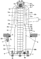
Fig. 1 is the partial sectional view according to the lightning arrester of first embodiment of the invention;
Partial sectional view among Fig. 2 has been represented the lightning-arrest element heap of the moulding in the first embodiment of the invention;
Fig. 3 is the equipotential distribution map of the lightning arrester of first embodiment of the invention;
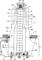
Partial sectional view among Fig. 4 has been represented the lightning arrester according to second embodiment of the invention;
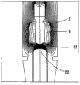
Partial sectional view among Fig. 5 has been represented the lightning arrester according to third embodiment of the invention;
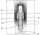
Fig. 6 is the equipotential distribution map of the lightning arrester of third embodiment of the invention;
Fig. 7 is the partial sectional view of the insulator cap in the four embodiment of the invention;
Fig. 8 is the equipotential distribution map of the insulator cap in the four embodiment of the invention;
Fig. 9 is the partial sectional view of the lightning arrester of fifth embodiment of the invention;
Figure 10 is the equipotential distribution map of the lightning arrester of fifth embodiment of the invention;
Figure 11 is the partial sectional view of the lightning arrester of sixth embodiment of the invention;
Figure 12 is the equipotential distribution map of the lightning arrester of sixth embodiment of the invention;
Figure 13 is the partial sectional view of the lightning arrester of seventh embodiment of the invention;
Figure 14 is the equipotential distribution map of the lightning arrester of seventh embodiment of the invention;
Figure 15 is the partial sectional view of the lightning arrester of eighth embodiment of the invention;
Figure 16 is the partial sectional view of lightning arrester in the prior art;
Figure 17 is the partial sectional view of lightning arrester in the prior art;
Partial sectional view among Figure 18 has been represented insulator cap of the prior art.
Embodiment
Hereinafter will be described the preferred implementation of having used lightning arrester of the present invention with reference to accompanying drawing.Wherein, In the description hereinafter; " top " of " top " of the lightning-arrest element heap of moulding, " top " of lightning-arrest element heap and sleeve is meant that respectively the lightning-arrest element heap of moulding, lightning-arrest element heap and sleeve are on high-tension side that end, and these tops are corresponding to the upwards direction in the accompanying drawing.In addition, " rear end " of " rear end " of the lightning-arrest element heap of moulding, " rear end " of lightning-arrest element heap and sleeve is meant the end opposite on top, and these rear ends are corresponding to the downward direction in the accompanying drawing.
[first execution mode]
Partial sectional view among Fig. 1 has been represented a kind of instance of lightning arrester of the present invention, and this lightning arrester belongs to the 66/77kV grade.
In this accompanying drawing, the electric equipment that has lightning arrester of the present invention comprises apparatus casing 1, and this housing is holding electric equipment (not shown)s such as switch hermetically.And, for example be SF
6Deng insulating gas filled in the apparatus casing 1.In addition, be provided with opening portion 1a in the bottom of apparatus casing 1, and sleeve 2 is installed among this opening portion 1a, so that the top of sleeve 2 self is positioned at the inside of apparatus casing 1, the rear end of sleeve 2 self then is covered with opening portion 1a hermetically.The lightning-arrest element heap 6 of moulding is releasably attached in this sleeve 2, and wherein, the lightning-arrest element heap 6 of this moulding has the lightning-arrest element heap 61 that hereinafter will be mentioned.
Sleeve body 3 comprises: the cylindrical shape part 51 of upper end closed (hereinafter referred to as " going up cylindrical portions may "), and it has patchhole 51a (hereinafter is referred to as " going up patchhole "), the top that is used to hold the lightning-arrest element heap 6 of moulding; Cylindrical shape part 52 (hereinafter is referred to as " following cylindrical portions may "), it has patchhole 52a (hereinafter is referred to as " following patchhole "), and it is used to hold the bottom of the lightning-arrest element heap 6 of moulding; And cylindrical shape part 53 (hereinafter is referred to as " middle cylinder part "), it has patchhole 53a (hereinafter is referred to as " taper patchhole "), is used to hold the tapered segment 67b on that hereinafter will be mentioned, the lightning-arrest element heap 6 of moulding.And at the mounting flange 52b that is provided with annular the ring week of middle cylinder part 53 upper positions continuously, it protrudes out on diametric(al).Under this condition; The diameter of following patchhole 52a is greater than the diameter of last patchhole 51a; In addition; Taper patchhole 53 has the inner surface 53b of taper, and it extends to the rear end of sleeve from the top of sleeve 2 with the form that awl expands, and goes up patchhole 51a and utilize this cone-shaped inner surface 53b and following patchhole 52a to couple together.In addition, the external diameter of middle cylinder part 53 approaches or is slightly less than the diameter of apparatus casing 1 upper shed part 1a, and the external diameter of mounting flange 52b is greater than the diameter of apparatus casing 1 upper shed part 1a.
High-tension shielding electrode 4 comprises: bell shield 41, and it is embedded in the cylindrical portions may 51, and crosses over remain silent the part 51b and the rear end of going up cylindrical portions may 51 coaxially; Tubular portion (hereinafter is referred to as " insertion portion of joint conductor ") 42, its centre at shield 41 horizontal components protrudes out the top to the part 51b that remains silent; And main line terminals 43, it is by continuously on the upper part of joint conductor patchhole 42, and is connected with main line conductor (not shown).
Wherein, the form that the sidewall sections 41a of shield 41 is made into to expand with awl is extended to the back-end from the top, and its axial length is that the part 51b that remains silent from last cylindrical portions may 51 is near the length middle cylinder part 53 tops.That is to say that this axial direction length can make the top of above-mentioned cone-shaped inner surface 53b be in the inboard of shield 41 sidewall sections 41a rear side end.Simultaneously; Joint conductor patchhole 42 has such function: as the patchhole of the joint conductor 62 (hereinafter will be mentioned) on the lightning-arrest element heap 6 of moulding, and also have such function built in the main line earth terminal 43 of joint conductor insertion portion 42 top ends: as the retaining plug of helical spring 63 (hereinafter will be mentioned) on the lightning-arrest element heap 6 of moulding.
Shown in accompanying drawing; About having the high-tension shielding electrode 4 of this structure; Main line terminals 43 protrude out away from the last cylindrical portions may 51 part 51b that remains silent, and are embedded into coaxially in the cylindrical portions may 51, thereby make sidewall sections 41a be arranged in the sidewall sections 51c of cylindrical portions may 51.
For the sleeve with said structure 2; Because the last cylindrical portions may 51 and the middle cylinder part 53 of sleeve 2 are arranged in apparatus casing 1; And following cylindrical portions may 52 is led to the outside of apparatus casing 1 through opening portion 1a; So the upper surface of mounting flange 52b contacts with the lower surface in apparatus casing 1 opening portion 1a ring week zone.Thereby, through encircling in the annular groove in all zones and to arrange O shape circle P1 being arranged at apparatus casing 1 opening portion 1a, and being arranged on the bolt V1 on the mounting flange 52b through screwing, just can sleeve 2 be installed among the opening portion 1a of apparatus casing 1 hermetically.
As shown in Figure 2, the lightning-arrest element heap 6 of moulding comprises: piled up the lightning-arrest element heap 61 of a plurality of lightning-arrest element 61a, lightning-arrest element wherein with zinc oxide as main component; Be installed in lightning-arrest element and pile the joint conductor 62 of 61 tip side (high-pressure side); Be installed in the helical spring 63 of joint conductor 62 tip side (high-pressure side); Be installed in lightning-arrest element and pile the pressure metal counterpart 65 of 61 rear end side (low-pressure side); Be installed in the helical spring 66 (hereinafter is referred to as " rear end side spring ") of pressure metal counterpart 65 belows; And the molded rubber body 67 that constitutes by materials such as silicon rubber, it is around lightning-arrest element heap 61, and between joint conductor 62 and pressure metal counterpart 65 molded integratedly forming.
Wherein, the shape of molded rubber body 67 outer surfaces is made into corresponding with the shape of sleeve 2 patchholes (going up patchhole 51a, following patchhole 52a, taper patchhole 53a) inner surface.Particularly, be respectively: the tip side (high-pressure side) at molded rubber body 67 is provided with and the contacted minor diameter section 67a of the inner surface of last patchhole 51a; Centre portion at molded rubber body 67 is provided with tapered segment 67b, and it has the contacted conical outer surface 67c with the cone-shaped inner surface 53b of taper patchhole 53a; Be provided with the contacted expanded diameter section 67d of inner surface with following patchhole 52a in the rear end side (low-pressure side) of molded rubber body 67.In addition, the spring constant of tip side spring 63 is set to the total spring constant (total spring constants of a plurality of rear end side springs 66) less than rear end side spring 66.Simultaneously, determine and the corresponding lightning-arrest element 61a number of system voltage according to the voltage of predetermined variable resistance.This execution mode is applicable to the high voltage power cable circuit of 77kV.
Ring week place at lightning-arrest element heap 61 with this structure; Be provided with the molded rubber body of processing by materials such as silicon rubber 67; And this rubber bodies is set to following state: contact with the lower surface of the circular plate part 62a of top end joint conductor 62; And contact with the roof pressure part 65b of rear end pressure metal counterpart 65, and cross over the upper surface portion of joint conductor 62 circular plate part 62a and the circumference of pressure metal counterpart 65.And, utilizing this molded rubber body, can the element heap 61 of taking shelter from the thunder be combined as a whole with joint conductor 62 and pressure metal counterpart 65.
Introduce the method that the lightning-arrest element heap 6 of moulding is releasably attached in the sleeve 2 below.
At first; Tip side spring 63 is installed among the cylindrical shape part 62b of joint conductor 62; So that the top of tip side spring 63 can be stretched from cylindrical shape part 62b convexity; And rear end side spring 66 is installed among the groove part 65c of pressure metal counterpart 65, so that the bottom of rear end side spring 66 can be stretched from groove part 65c convexity.And; As shown in Figure 1; Do not applying under the state of elastic force to tip side spring 63 and rear end side spring 66; The top (high-pressure side) of the lightning-arrest element heap 6 of moulding is inserted in the sleeve 2, and the top of the lightning-arrest element heap 6 of moulding is pushed, up to the top that makes tip side spring 63 with till the inner wall surface of main line terminals 43 contacts.Therefore; Be installed in single parts (not shown) cylindrical shape part 62b, that constitute conductive contact piece (multiple spot contact) and realize that with the interior perimeter surface of joint conductor insertion portion 42 conduction contacts; In addition; The interior perimeter surface of patchhole 51a contacts on the path part 67a of molded rubber body 67 and the sleeve 2; The tapering part 67b of molded rubber body 67 contacts with the interior perimeter surface of taper patchhole 53a, and the large-diameter portion of molded rubber body 67 divides 67d to contact with the interior perimeter surface of following patchhole 52a.
Under this condition, the internal diameter of the external diameter of tip side spring 63 and joint conductor 62 cylindrical shape part 62b much at one, and the external diameter of rear end side spring 66 is seldom identical with the difference in internal diameters of pressure metal counterpart 65 upper groove part 65c.
Then, the bottom surface of the 2 times cylindrical portions may 52 of seal closure F and sleeve that are made up of plate shape metal counterpart is contacted, and utilize along on the bottom surface of circumferential arrangement cylindrical portions may 52 under near a plurality of bolt V2 the seal closure F circumference are fixed to the sealing cover.Therefore, rear end side spring 66 is compressed between the upper surface of the rear portion of groove part 65c and seal closure F, thereby makes rear end side spring 66 produce axial elastic force.Afterwards; The lightning-arrest element heap 6 of moulding is pushed to the top of sleeve 2 further by the elastic force of rear end side spring 66; Thereby between the interior perimeter surface of the tapering part 67b of molded rubber body 67 and taper patchhole 53a, produce predetermined surface pressing; And tip side spring 63 is compressed between the inner wall surface of remain silent part (upper surface of joint conductor 62) and the main line terminals 43 of cylindrical shape part 62b, thereby makes tip side spring 63 produce axial elastic force (acting on the reaction force on the lightning-arrest element heap 6 of moulding).Meanwhile, in Fig. 1, label N refers to the embedded metal counterpart with tapping hole, and it is embedded into the lower surface of 2 times cylindrical shape parts 52 of sleeve, and the top of bolt V2 is screwed in the tapping hole.
Fig. 3 is the equipotential distribution map of the lightning arrester of this execution mode.Can be clear that from this accompanying drawing: because the top of lightning-arrest element heap 61 shielded by high-tension shielding electrode 4, so electric field does not focus on above-mentioned lightning-arrest element and piles 61 tops; And because the outside as the apparatus casing 1 of grounding electrode is installed in the rear end of lightning-arrest element heap 61; So electric field does not concentrate on the rear end of lightning-arrest element heap 61 yet, in addition; Mid portion at lightning-arrest element heap 61; Because can be through regulating high-tension shielding electrode 4 and suitably controlling electric field, so electric field does not concentrate on the above-mentioned pars intermedia office of lightning-arrest element heap 61 yet as the spacing between the apparatus casing 1 of grounding electrode.
Hereinafter will be explained shield 41 and as the influence of 1 pair of lightning-arrest element heap 61 of the apparatus casing of grounding electrode.At first; If the spacing between shield 41 rear ends and apparatus casing 1 upper surface is very short; Then just have following relation: receive the influence of shield 41 and apparatus casing 1, the electric field that lightning-arrest element is piled 61 mid portions becomes intensive, in contrast; If this spacing is very big, then just have following relation: the electric field that lightning-arrest element is piled above-mentioned mid portion becomes sparse.Thereby, even only become to make spacing to increase structural configuration, also be difficult to voltage distribution carrying out equilibrium to lightning-arrest element 61a with two aspect results.For this problem; In this execution mode; (length be about lightning-arrest element heap 61 1/3) and mid portion because the top of lightning-arrest element heap 61 (length be about lightning-arrest element pile 61 1/3) be arranged in apparatus casing 1; And the rear end of lightning-arrest element heap 61 (length be about lightning-arrest element heap 61 1/3) is positioned at the outside of apparatus casing 1; Through suitably regulating high-tension shielding electrode 4 and, can doing suitable adjusting to the electric field that lightning-arrest element is piled in 61 mid portions as the spacing between the apparatus casing 1 of grounding electrode.Therefore, can realize the equilibrium that lightning-arrest element 61a voltage distributes.
As stated; For lightning arrester, at first,, the element of will taking shelter from the thunder is releasably attached in the sleeve 2 because piling the outside of 61 slave unit housings 1 with this structure; And sleeve 2 can be installed among the opening portion 1a of apparatus casing 1 with being sealed; So, needn't hold a jar type lightning arrester at present known gas-insulated spacer assembly is installed, and the structure of ability simplified apparatus.Secondly, when carrying out withstand voltage test, to apparatus casing 1 inside compile or the operation that fills insulating gas just can become unnecessary.The 3rd, be positioned at the outside of apparatus casing 1 through a part (low-pressure side) that makes lightning-arrest element heap 61, can realize the miniaturization of equipment.The 4th; Be installed in the sleeve 2 through the lightning-arrest element heap 6 of the moulding that will comprise lightning-arrest element heap 61; Because piling the shield 41 that is embedded in the cylindrical portions may 51 of 61 upper end side (high-pressure side) on every side, lightning-arrest element blocking; Realize equilibrium so the voltage of lightning-arrest element 61a is distributed, thereby the equipment that makes can be applicable to the high voltage power cable circuit of 66/77kV grade.The 5th, through with molded rubber body roof pressure to the top of sleeve, can guarantee the surface pressing between sleeve patchhole inner surface and the molded rubber external surface, thereby can prevent occurring dielectric breakdown at the interface.The 6th, through rear end installation rear end side spring 66, and, can the lightning-arrest element of moulding be piled the top of 6 roof pressures to sleeve 2 through making above-mentioned rear end side spring 66 produce elastic forces at the lightning-arrest element heap 6 of moulding.The 7th, the conical outer surface through making molded rubber body 67 and the cone-shaped inner surface of sleeve 2 are suitable, and the strength that axially resists as surface pressing is played a role effectively.That is to say, produce predetermined surface pressing between the inner peripheral surface of tapering part 67b and taper patchhole 53c of molded rubber body 67, can improve the insulation property at place, two process median surfaces through making.The 8th; Through the effect of the elastic force of rear end side spring 66 and the effect of tip side spring power are combined, can be between lightning-arrest element 61a and joint conductor 62, between the lightning-arrest element 61a and the surface pressing that generation is scheduled between lightning-arrest element 61a and the roof pressure part 65b.The 9th, when equipment is carried out voltage-withstand test,, can utilize the elastic force of tip side spring 63 that the lightning-arrest element heap 6 of moulding is released to the rear end side of sleeve 2, thereby can easily remove the lightning-arrest element heap 6 of dismounting through seal closure F is removed.
[second execution mode]
Fig. 4 is the partial sectional view of the lightning arrester of second embodiment of the invention.Simultaneously, in this accompanying drawing, with identical Reference numeral refer to those with Fig. 1 in the identical part of counterpart, and omit detailed description.
In this embodiment, through making sleeve 2, can form the cut-off region Z of electric current in sleeve 2 rear end of leading to apparatus casing 1 outside with insulating material such as epoxy resin.Particularly, the cut-off region Z of electric current is positioned at such part: its end face from following cylindrical portions may 52 rear ends extends the outer wall to apparatus casing 1, and wherein, following cylindrical portions may 52 is as the pipe of insulation.
Lightning arrester for this structure; Outside at apparatus casing 1; That is to say through earthing conductor E-being installed at the current cut-off zone Z that is positioned at sleeve 2 rear end; Through between the low-pressure side of the outer wall of apparatus casing 1 and lightning-arrest element heap 61, earthing conductor E being set, can easily measure the leakage current of lightning-arrest element heap 61.Particularly; Through the end with earthing conductor E be installed to apparatus casing 1 iso-electric bolt V1 on; And be installed to and the low-pressure side of the element heap 61 of taking shelter from the thunder is iso-electric and pass on the bolt V2 of pressure metal counterpart 65 and seal closure F through the other end with earthing conductor E; And through utilizing current transformer H to detect to flow through the electric current of earthing conductor E, pile 61 leakage current with regard to the energy measurement element that goes out take shelter from the thunder.
As stated; For such lightning arrester; Because leading to apparatus casing 1 outside sleeve 2 rear ends (following cylindrical portions may 52) is processed by insulating material such as epoxy resin; And be installed in the sleeve 2 owing to comprise the lightning-arrest element heap 6 of the moulding of lightning-arrest element heap 61, so it is regional between the low-pressure side of the outer wall of apparatus casing 1 and lightning-arrest element heap 61, to form current cut-off.And, in the outside of apparatus casing 1,, can easily measure the leakage current of lightning-arrest element heap 61 through between the low-pressure side of apparatus casing 1 outer wall of blocking electric current and lightning-arrest element heap 61, earthing conductor E being installed.Thereby; For the lightning arrester of this structure, when measuring leakage current, need not insulating gas is compiled or is filled in the inside of apparatus casing 1; In addition; Since needn't in apparatus casing 1, insulator be installed, thus can realize miniaturization, simplification, the lightweight of device structure, and cost is reduced.
[the 3rd execution mode]
Fig. 5 (a) is the partial sectional view of the lightning arrester of third embodiment of the invention, and the vertical view among Fig. 5 (b) has been represented the seal closure in this execution mode.Simultaneously, in this accompanying drawing, with identical Reference numeral refer to those with Fig. 1 in the identical part of counterpart, and omit detailed description.
In Fig. 5 (a), the lightning-arrest element heap 6 of moulding has: the lightning-arrest element heap 61 that a plurality of lightning-arrest stacked elements form, lightning-arrest element wherein with zinc oxide as main component; Joint conductor 62, it is installed on the tip side (high-pressure side) of lightning-arrest element heap 61; Columniform pressure metal counterpart 64, it is installed to the rear end side (low-pressure side) of lightning-arrest element heap 61; And molded insulator 67d, it is made up of materials such as silicon rubber, and this insulator ring is around lightning-arrest element heap 61, and moulding integratedly between joint conductor 62 and pressure metal counterpart 64.And, between the patchhole of mold insulation body 67d and sleeve 2, gas blanket G is set.
The thickness of above-mentioned mold insulation body 67d is enough to lightning-arrest element heap 61, joint conductor 62 and pressure metal counterpart 64 are combined; Under the situation that lightning-arrest element heap 6 is placed in the sleeve 2 with moulding; Through the above-mentioned thickness of attenuate as much as possible, can be between the patchhole of the lightning-arrest element heap 6 of moulding and sleeve 2 (top patchhole 51a, middle patchhole 53a, patchhole 52a) down formation gas blanket G.In addition, through around lightning-arrest element heap 61, suchlike mold insulation body 67d being set, can weaken the electric field that lightning-arrest element is piled 61 outer surfaces.
With this understanding, the formed body of plastic resin materials such as rubber capable of using, epoxy resin constitutes mold insulation body 67d, to replace the formed body that is made up of silicon rubber.Meanwhile, in Fig. 5, label 68 refers to the tabular seal closure that is installed on 2 times cylindrical portions may 52 bottom surfaces of sleeve, and it is used to seal down patchhole 52a, and sealing cover 68 is made up of metal counterparts such as aluminium counterparts.In addition; Centre at sealing cover 68 upper surfaces is shaped on circular groove part 68a; Its shape is almost completely identical with the shape of pressure metal counterpart 64, shown in Fig. 5 (b), around ring week; Be provided with bolt-inserting hole H3 (for example being four), these bolt-inserting holes are along circumferentially distributing equally spacedly.In addition, at the bottom surface side of 2 times cylindrical portions may 52 of sleeve, the embedded metal counterpart N that will have a tapping hole be embedded into seal closure 68 on the corresponding position of bolt-inserting hole H3.Simultaneously, the label H4 among Fig. 5 (b) refers to the bolt-inserting hole that is used to insert the grounding electrode terminals.
In addition; In this embodiment, diameter is installed among the cylindrical portions may 62b of joint conductor 62 with the few identical tip side helical spring 63 of the difference in internal diameters of joint conductor 62 cylindrical portions may 62b, so that the top of tip side spring 63 protrudes out away; Under this state; The top (high-pressure side) of the lightning-arrest element heap 6 of moulding is inserted in the sleeve 2, and the top of tip side spring 63 receives ejection, till the inner wall surface 43a that makes it with main line terminals 43 contacts.Thereby; The single parts (not shown) that constitutes conductive contact piece (multiple spot contact) realizes that with the interior perimeter surface of joint conductor insertion portion 42 conduction contacts; In addition; Lightning-arrest element heap 6 removably is inserted into inserting in the hole of sleeve 2, and wherein, described conductive contact piece is installed among the annular groove 62c of joint conductor 62.
Then; Be installed to through bottom among the groove part 68a of seal closure 68 pressure metal counterpart 64; And the bottom surface of the 2 times cylindrical portions may 52 of upper surface side and sleeve through making above-mentioned seal closure 68 contacts; And through with the top of fastening bolt V2 in the downside surface of seal closure 68 is screwed to the tapping hole of sleeve 2 embedded metal counterpart N-promptly through seal closure 68 being contacted with the bottom surface of following cylindrical portions may 52 and seal closure 68 being fixed to down on the bottom surface of cylindrical portions may 52; Just can the lightning-arrest element heap 6 of moulding be pressed to the top of sleeve 2; And can push in the axial direction and be positioned at lightning-arrest element and pile the tip side spring 63 on 6 tops, make this tip side spring 63 produce predetermined elasticity power.Thereby, because between lightning-arrest element 61a and the joint conductor 62, between the element 61a that takes shelter from the thunder and produced predetermined elasticity power between lightning-arrest element 61a and the pressure metal counterpart 64, so can guarantee being in contact with one another of these parts.
Fig. 6 has represented the equipotential distribution map of the lightning arrester of this execution mode.Can be clear that from this accompanying drawing: the top of element heap 61 is being shielded by high-tension shielding electrode 4 because moulding is taken shelter from the thunder, so electric field does not focus on above-mentioned top end; And because the outside as the apparatus casing 1 of grounding electrode is installed in the rear end of lightning-arrest element heap 61; So electric field does not concentrate on described rear end yet, in addition; Mid portion at the lightning-arrest element heap 61 of moulding; Because can be through regulating high-tension shielding electrode 4 and suitably controlling electric field, so electric field does not concentrate on above-mentioned pars intermedia office yet as the spacing between the apparatus casing 1 of grounding electrode.
As stated; Lightning arrester for this structure; Between the patchhole of mold insulation body 67d and sleeve 2, be provided with gas blanket G, the shock wave that when the earth fault current that surpasses nominal discharge current far away is flowed through lightning arrester, is produced can discharge (pressure release) from the positions such as gap at sleeve 2 sealing positions through this gas blanket G.That is to say, between the lower surface of 2 times cylindrical portions may 52 of sleeve and seal closure 68, the O type circle P2 that is used to seal has been installed, when lightning-arrest element took place to puncture, under the effect that raises in 2 internal pressure moments of sleeve, seal closure 68 self can deform.This shock wave can discharge (pressure release) from the gap location that produces between 2 times cylindrical portions may 52 lower surfaces of sleeve and the seal closure 68, and wherein, this gap is to be caused by above-mentioned distortion.Thereby above-mentioned shock wave is difficult to propagate on the sleeve.Therefore, can prevent the dispersion of lightning-arrest element.
[the 4th execution mode]
Partial sectional view among Fig. 7 has been represented insulator cap, and it is releasably attached in the sleeve, to replace the lightning-arrest element heap 6 of above-mentioned moulding.Meanwhile, in this accompanying drawing, refer to identical label with the part that counterpart is identical among Fig. 1 and Fig. 2, and omit detailed description these parts.
As shown in Figure 7, insulator cap 20 of the present invention has: insulator cap body 21, and it is installed among the taper patchhole 53a of sleeve 2; Columnar contact component 22, it is disposed in the top of insulator cap body 21, and is installed to coaxially among the last patchhole 51a of sleeve 2 with last cylindrical portions may 51; The cylindrical shape press member 23 of upper end closed, it is positioned at the below of insulator cap body 21, and is installed to coaxially among the following patchhole 52a of sleeve 2 with following cylindrical portions may 52.With this understanding; This contact component 22 is that the metal counterpart by materials such as aluminium alloys constitutes; And its diameter is less than the diameter of patchhole on the sleeve, and in addition, its axial length equals high-tension shielding electrode 4 inwall tops to the spacing between the high electrode 27 upper wall 27b of extrusion (hereinafter will be mentioned).Particularly; Insulator cap 20 is being installed under the situation of tram in the sleeve 2; The axial length of contact component 22 makes its top realize that conduction contacts with the top of high-tension shielding electrode 4 inwall 41b, and makes the rear end of contact component 22 realize that with the upper wall of high voltage side electrode 27 conduction contacts.In addition, press member 23 is made up of metal counterparts such as aluminium alloys, and on a part of cylindrical portions may along axially being provided with thick wall part 23a.In addition, on the part 23b that remains silent of press member 23, be provided with a plurality of bolt-inserting hole 23c, and these patchholes if necessary, can be provided with tapping hole 23d along circumferentially equidistantly distributing on the rear end surface of thick wall part 23a.
With this understanding, the outer surface of conical portion 25 has the suitable conical outer surface 25a with the cone-shaped inner surface 53b of sleeve 2, and the diameter of low-voltage side electrode 26 is slightly less than the diameter of stylolitic part 24.In addition; The bottom surface of low-voltage side electrode 26 is embedded; So that be in same horizontal plane with the bottom surface of stylolitic part 24, and be provided with a plurality of spring accommodation hole 26b and a plurality of tapping hole 26c, and make these holes circumferentially equidistantly arrange in the upper edge, bottom surface of above-mentioned low-voltage side electrode 26.
The insulator cap of introducing this structure below 20 is releasably attached to the method in the sleeve 2.
At first, the bolt V2 shown in Fig. 1 is disassembled, and seal closure F removed from the following cylindrical portions may 52 of sleeve 2, and the lightning-arrest element heap 6 of moulding is taken out from sleeve 2.
Then, as shown in Figure 7, spring 28 is set among the spring accommodation hole 26b of low-voltage side electrode 26; So that its underpart is stretched from spring accommodation hole 26b convexity; Afterwards, bolt V3 is inserted among the bolt-inserting hole 23c, and its top is screwed among the tapping hole 26c of low-voltage side electrode 26.Like this, utilize the axial component 29a of bolt V3 that press member 23 has been installed on the low-voltage side electrode 26, thereby it is freely moved forward and backward.And; Spring 28 is produced under the state of elastic force; Contact component 22, insulator cap body 21 and press member 23 are inserted in the sleeve 2, and ejection is carried out on the top of contact component 22, till the top that makes it with high-tension shielding electrode inner wall 41b contacts.Thereby the conical outer surface 25a of insulator cap body 21 conical portions 25 realizes contacting with the cone-shaped inner surface 53b of sleeve 2.
Afterwards, as aforesaid situation, seal closure F contacts with the bottom surface of 2 times cylindrical portions may 52 of sleeve.And utilize a plurality of bolt V2 that seal closure F is fastened to down on the bottom surface of cylindrical portions may 52.Thereby, utilize the axial component 29a of bolt V3 that ejection is carried out on the surface of press member 23 upper ends, till the surface that makes it with low-voltage side electrode 26 lower ends contacts, thereby spring 28 receives ejection in the axial direction, therefrom the elastic force in the generation axially.
In addition, when spring 28 produced the axial elasticity power, because the press member 23 that constitutes insulator cap 20 is by the top of ejection to sleeve 2, institute was so that the surface pressing that office, the mating part generation of insulator cap body 21 conical outer surface 25a and sleeve 2 cone-shaped inner surface 53b is scheduled to.
Fig. 8 has represented the equipotential distribution map of insulator cap in this execution mode.Can find out from this figure,, block owing to constitute the top ring periderm high-tension shielding electrode 4 of the insulator cap body 21 of insulator cap 20 through insulator cap 20 is installed on the tram in the sleeve 2, so, can suitably expand the electric field in the insulator cap body 21 obviously.
As stated; For the insulator cap of this structure, when carrying out test such as withstand voltage test, be installed to inserting in the hole of sleeve 2 through insulator cap with the lightning-arrest element 6 of replaceable moulding; Just can guarantee: under the state that lightning-arrest element heap 6 takes out with moulding, insulate in the inside of sleeve 2 patchholes.In addition, through insulator cap 20 being arranged on the inside of the concentrated high-tension shielding electrode 4 rear end side ends of electric field, can under the state that insulator cap 20 has been installed, control electric field effectively.In addition, owing to only just can guarantee the insulativity that sleeve 2 patchholes are inner through near the inside sealed high pressure bucking electrode 4 rear side end, so can realize the miniaturization of insulator cap 20.
[the 5th execution mode]
Fig. 9 is the partial sectional view of the lightning arrester of fifth embodiment of the invention.Equally, in this accompanying drawing, with identical Reference numeral refer to those with Fig. 1 in the identical part of counterpart, and omit detailed description.
As shown in Figure 9, in this embodiment, on the outer surface on sleeve 7 tops, be provided with conductive coating 75, dot among the figure.
With this understanding, the sleeve 7 in the 5th execution mode has: middle cylinder part 71 near the circumference on surface, is provided with circular groove part 71a above that; Last cylindrical portions may 72, the upper end of itself and middle cylinder part 71 couples together continuously and coaxially, and its diameter is less than the external diameter of middle cylinder part 71, and has the tapering part 72a of convergent, and remain silent in the upper end of this tapering part; Following cylindrical portions may 73, near the circumference of middle cylinder part 71 bottom surfaces, itself and middle cylinder part 71 couple together continuously and coaxially, and its diameter is less than the external diameter of middle cylinder part 71; Main line terminals 74; It is embedded in the remain silent middle position of part 72b of cylindrical portions may 72, so that its top stretches from the part 72b convexity of remaining silent, simultaneously; In the sleeve 7 of this execution mode; The external diameter of middle cylinder part 71 is greater than the diameter of apparatus casing 1 opening portion 1a, and the bottom surface of middle cylinder part 71 circumference is pressed onto on the end face of apparatus casing 1 by seat, and is fixed up hermetically.
The conductive coating (coating that for example constitutes) that accompanying drawing sign 75 refers to as the high-tension shielding electrode by aluminium paint.And conductive coating 75 is coated in and is covered with cylindrical portions may 72 the remain silent outer surface of part 72b, the outer surface of conical portion 72 and the outer surface of semi-circular portion 71b, and semi-circular portion 71b has wherein constituted the groove part 71a of middle cylinder part 71.
Figure 10 is the equipotential distribution map of lightning arrester in the 5th execution mode.Can find out from this accompanying drawing:, in this embodiment, same because the top of lightning-arrest element heap 61 is used as 75 shieldings of conductive coating of high-tension shielding electrode as the lightning arrester first execution mode; So at above-mentioned top end, electric field is not concentrated; And because the outside as the apparatus casing 1 of grounding electrode is installed in the rear end of lightning-arrest element heap 61, electric field is not concentrated herein yet, in addition; Pars intermedia office at lightning-arrest element heap 61; Owing to can control electric field through adjustment conductive coating 75 and as the spacing between the apparatus casing 1 of grounding electrode, so electric field can not concentrated in above-mentioned pars intermedia office yet.
As stated, in the lightning arrester of the 5th execution mode, can realize the equalization that voltage distributes on the lightning-arrest element equally.And, in this embodiment, because the high-tension shielding electrode 4 that is provided with conductive coating 75 rather than constitutes by the metal counterpart, so, compare with the lightning arrester in first execution mode, the ability weight reduction, and reduce cost.Simultaneously, the lightning arrester in this execution mode is applicable to the electric equipment of gas-insulated type or the electric equipment of air insulation type.
[the 6th execution mode]
Figure 11 is the partial sectional view according to the lightning arrester of sixth embodiment of the invention.Equally, in this accompanying drawing, with identical Reference numeral refer to those with Fig. 1 in the identical part of counterpart, and omit detailed description.
Shown in figure 11, in this embodiment, on the top of sleeve 8, be provided with other high-tension shielding electrode 10, and be fixed in this.
With this understanding, the sleeve 8 in the 6th execution mode has: the middle cylinder part 81 of convergent; With the last cylindrical portions may 82 that the upper end of middle cylinder part 81 couples together continuously and coaxially, its diameter is less than the external diameter of middle cylinder part 81; Following cylindrical portions may 83, it is coaxial and couple together continuously at its lower end with middle cylinder part 81, and the diameter of this part is substantially the same with the external diameter of middle cylinder part 81 lower ends.Ring on following cylindrical portions may 83 tops is provided with circular mounting flange 83a continuously on week.
High-tension shielding electrode 10 has: columnar metal counterpart 11, and its upper end is sealed; And main line terminals 13, it is installed on the enclosure portion of metal counterpart 11, and extends upward from the part 12 of remaining silent.
As shown in the figure; High-tension shielding electrode 10 for this structure; Main line terminals 13 are installed on the upper position of cylindrical portions may 82; And the sidewall sections 14 of metal counterpart 11 is placed on the top of cylindrical portions may 82 coaxially, thereby surrounds the sidewall sections 82a of cylindrical portions may 82, and is fixed on this.
Figure 12 is the equipotential distribution map of lightning arrester in the sixth embodiment of the invention.Can find out from this accompanying drawing:, in this embodiment, same because the top of lightning-arrest element heap 61 is configured 11 shieldings of cylindrical metal counterpart of high-tension shielding electrode 10 as the lightning arrester first execution mode; So at above-mentioned top end, electric field is not concentrated; And because the outside as the apparatus casing 1 of grounding electrode is installed in the rear end of lightning-arrest element heap 61, electric field is not concentrated herein yet, in addition; Pars intermedia office at lightning-arrest element heap 61; Owing to can control electric field through adjustment cylindrical metal counterpart 11 and as the spacing between the apparatus casing 1 of grounding electrode, so electric field can not concentrated in above-mentioned pars intermedia office yet.
As stated, in the lightning arrester of the 6th execution mode, can realize that equally lightning-arrest element 61a goes up the equalization that voltage distributes.Simultaneously, the lightning arrester in this execution mode is applicable to the electric equipment of fluid insulated type, the electric equipment of gas-insulated type or the electric equipment of air insulation type.
[the 7th execution mode]
Figure 13 is the partial sectional view according to the lightning arrester of seventh embodiment of the invention.Equally, in this accompanying drawing, with identical Reference numeral refer to those with Fig. 1 and Figure 11 in the identical part of counterpart, and omit detailed description.
Shown in figure 13, in this embodiment, high-tension shielding electrode 10 shown in Figure 11 is placed on the top of sleeve 9, and is fixed in this, and the insulation barrier 91b that the ring periderm hereinafter of high-tension shielding electrode 10 is described is blocking.
With this understanding, the sleeve 9 in the 7th execution mode has: go up cylindrical portions may 91, be provided with circular groove part 91a near the circumference on surface above that; And following cylindrical portions may 92, its lower end with last cylindrical portions may 91 is coaxial and couple together continuously, and its diameter is less than the external diameter of last cylindrical portions may 91.In addition, have in the high-tension shielding electrode 10 of same structure with high-tension shielding electrode shown in Figure 11, sidewall sections 14 is installed among the groove part 91a of cylindrical portions may 91 coaxially.Simultaneously, in the sleeve 9 of this execution mode, the external diameter of last cylindrical portions may 91 is greater than the diameter of apparatus casing 1 opening portion 1a, and upward the bottom surface in 91 ring weeks of cylindrical portions may is placed on the inner surface of apparatus casing 1, and is fixed on this hermetically.
Figure 14 is the equipotential distribution map of lightning arrester in the seventh embodiment of the invention.Can find out from this accompanying drawing:, in this embodiment, same because the top of lightning-arrest element heap 61 is used as 11 shieldings of cylindrical metal counterpart of high-tension shielding electrode as the lightning arrester first execution mode; So at above-mentioned top end, electric field is not concentrated; And because the outside as the apparatus casing 1 of grounding electrode is installed in the rear end of lightning-arrest element heap 61, electric field is not concentrated herein yet, in addition; Pars intermedia office at lightning-arrest element heap 61; Owing to can control electric field through adjustment cylindrical metal counterpart 11 and as the spacing between the apparatus casing 1 of grounding electrode, so electric field can not concentrated in above-mentioned pars intermedia office yet.
As stated, in the lightning arrester of the 7th execution mode, the distribution that the element 61a that can balancedly all take shelter from the thunder equally goes up voltage.And; In the lightning arrester of this execution mode; Be installed to through sidewall sections 14 among the groove part 91a of cylindrical portions may 91 high-tension shielding electrode 10; Because insulation barrier parts 91b is around columnar metal counterpart 11, thus can shorten the insulation distance between the phase respectively or and apparatus casing 1 between insulation distance.Therefore, can realize the miniaturization of equipment.Simultaneously, the lightning arrester in this execution mode is applicable to the electric equipment of fluid insulated type, the electric equipment of gas-insulated type or the electric equipment of air insulation type.
[the 8th execution mode]
Figure 15 is the partial sectional view according to the lightning arrester of eighth embodiment of the invention.Equally, in this accompanying drawing, with identical Reference numeral refer to those with Fig. 1 and Fig. 2 in the identical part of counterpart, and omit detailed description.
Shown in figure 15, in this embodiment, as hereinafter was introduced, high-tension shielding electrode 20 was embedded in the top of the lightning-arrest element heap 6 of moulding.
With this understanding; In the sleeve 30 of the 8th execution mode; Joint conductor insertion portion 42 as shown in Figure 1 is embedded in the remain silent centre of part 51b of cylindrical portions may 51, and main line terminals 43 as shown in Figure 1 are arranged on the insertion portion 42 of joint conductor continuously.In addition; Interior perimembranous in last cylindrical portions may 51 is provided with bellmouth 31; It extends to end portion from the part 51b that remains silent with form of taper, and this bellmouth 31 lead to continuously in the middle of patchhole 32, the diameter of middle patchhole is identical with the diameter of following patchhole 52a.
High-tension shielding electrode 20 has: tabular horizontal component 21a; And the shield 21 of being inverted cup-shaped, it has sidewall sections 21b, and it is configured to vertical, thereby goes out from the circumferential extension of horizontal component 21a with the form of circular cone.Cylindrical portions may 62b shown in Figure 2 is installed to the centre on shield 21 horizontal component 21a tops, and protrudes out away.
Shown in accompanying drawing, for the high-tension shielding electrode 20 of this structure, horizontal component 21a contacts with the tip side (high-pressure side) of lightning-arrest element heap 61, and under this state, lightning-arrest element heap 61 is combined into one by the molded rubber body 67 that is arranged on its ring perimembranous.Meanwhile, the circumference on molded rubber body 67 tops is provided with tapering part 67d, and it contacts with the interior perimeter surface of bellmouth 31.
As stated, in this embodiment,, the top of lightning-arrest element heap 61 wrapping because being encircled by high-tension shielding electrode 20, so, equally can the upward distribution of voltage of balanced lightning-arrest element 61a.
Simultaneously, in the 8th execution mode,, also can above-mentioned high-tension shielding electrode 20 be installed to the ring week place of molded rubber body 67 although introduction is that high-tension shielding electrode 20 is embedded into the situation in the molded rubber body 67.
In the present invention, in appended claim institute restricted portion, can change or revise the present invention.
At first, in the above-described embodiment, sleeve is installed to the situation on apparatus casing 1 bottom, also can sleeve be installed on the sidewall of apparatus casing 1 although introduced.
Secondly; In the above-described embodiment; Although introduced the situation that lightning arrester of the present invention is applied to 66/77kV high voltage power cable circuit, can lightning arrester of the present invention be applied to be lower than the cable line of 66kV or be higher than on the Voltage Cable Lines Construction of 77kV equally.
Claims (27)
1. lightning arrester, it is positioned at the opening portion of the apparatus casing that is holding electric equipment, and this lightning arrester has:
Sleeve, it is installed into and is hiding said opening portion hermetically; And
Molded and shaped lightning-arrest element heap, it is releasably attached to inserting in the hole of said sleeve by the outside from said apparatus casing, in the lightning-arrest element heap of this moulding:
The lightning-arrest element heap of said moulding has lightning-arrest element heap, and this lightning-arrest element heap comprises the laminate stack that is made up of a plurality of lightning-arrest elements, and the lightning-arrest element heap of moulding also has the mold insulation body that is arranged on all positions of said lightning-arrest element heap ring, it is characterized in that:
Whole length of the lightning-arrest element heap of said moulding all are accommodated in the inside of said patchhole of sleeve.
2. lightning arrester according to claim 1 is characterized in that: under the inner state of the said patchhole that is housed inside sleeve, the lightning-arrest element heap of said moulding is sealed by seal closure.
3. lightning arrester according to claim 1 is characterized in that: said mold insulation body is that the formed body by electro-insulating rubber constitutes.
4. lightning arrester according to claim 1 is characterized in that: said sleeve is to be become by molding for epoxy resin system hard and that insulate.
5. lightning arrester according to claim 1 is characterized in that:
The top of said sleeve is provided with the main line terminals that are connected with the main line conductor of said electric equipment;
The tip side of the lightning-arrest element heap of said moulding is provided with the joint conductor that links to each other with said main line terminals.
6. lightning arrester according to claim 1 is characterized in that: the lightning-arrest element heap of said moulding comprises: lightning-arrest element heap, its laminate stack by a plurality of lightning-arrest elements constitutes, lightning-arrest element wherein with zinc oxide as main component; The joint conductor, its high-pressure side with said lightning-arrest element heap is connected; Pressure metal counterpart, it is connected on the low-pressure side of said lightning-arrest element heap; And molded and shaped insulator, it is set at the ring week position of said lightning-arrest element heap.
7. lightning arrester according to claim 6 is characterized in that: the mold insulation body that the lightning-arrest element heap of said moulding is set at around the said lightning-arrest element heap is combined into one.
8. lightning arrester according to claim 3 is characterized in that: in the inside of the said patchhole of sleeve, the lightning-arrest element heap of said moulding is pressed towards the top of sleeve.
9. lightning arrester according to claim 8 is characterized in that: the rear end side spring has been installed in the rear end at the lightning-arrest element heap of said moulding, by means of the extruding force on the axial direction, makes this spring produce elastic force.
10. lightning arrester according to claim 8; It is characterized in that: the inner surface of the said patchhole of sleeve has the inner surface of taper; It is coniformly from the top of said sleeve and extends the rear end to sleeve; And the outer surface of said mold insulation body is the outer surface of taper, with suitable with described cone-shaped inner surface.
11. lightning arrester according to claim 8 is characterized in that: the tip side spring has been installed on the top at the lightning-arrest element heap of said moulding, by means of the extruding force towards axial direction, makes this spring produce elastic force; And
The rear end side spring has been installed in rear end at the lightning-arrest element heap of said moulding, by means of the extruding force towards axial direction, makes this spring produce elastic force.
12. lightning arrester according to claim 11 is characterized in that: the spring constant of said tip side spring is set to the total spring constant that is lower than said rear end side spring.
13. lightning arrester according to claim 1 is characterized in that: insert in the hole the said of sleeve, insulator cap removably has been installed, to replace and to pile from the lightning-arrest element of the outside said moulding of changing of said apparatus casing.
14. lightning arrester according to claim 13 is characterized in that:
Said insulator cap comprises:
Be installed in the said insulator cap body that inserts in the hole of sleeve, it has the outer surface of taper, so that the cone-shaped inner surface of said sleeve and this outer surface are suitable;
Contact component, it is installed in the said of sleeve and inserts in the hole, and makes the high voltage side electrode of high-tension shielding electrode and insulator cap body realize electrically contacting; And
Press member, it is installed to the said of sleeve and inserts in the hole, and said insulator cap body is pressed to the tip side of said sleeve.
15. lightning arrester according to claim 13 is characterized in that:
Between the top end surface of the rear end surface of said insulator cap body and press member, spring is installed, this press member is pressed to said insulator cap body the tip side of said sleeve; And
The extruding force towards said sleeve top orientation of utilizing said press member to produce makes said spring produce elastic force.
16. lightning arrester according to claim 1 is characterized in that: the ring periderm high-tension shielding electrode on the lightning-arrest element heap of said moulding top is hiding.
17. lightning arrester according to claim 16 is characterized in that: the outside of housing is led in the rear end of said sleeve through the opening portion of said apparatus casing.
18. lightning arrester according to claim 17 is characterized in that: rear end through regulating said high-tension shielding electrode and the spacing between the said apparatus casing inner surface, the electric field of said lightning-arrest element heap mid portion is controlled.
19. lightning arrester according to claim 16 is characterized in that: the ring week of said high-tension shielding electrode is blocked by insulation barrier.
20. lightning arrester according to claim 16 is characterized in that: said high-tension shielding electrode has the metal counterpart, and its shape is almost completely identical with the shape on said sleeve top; And
Said metal counterpart and said sleeve are embedded in the top of sleeve coaxially.
21. lightning arrester according to claim 16 is characterized in that: said high-tension shielding electrode is to constitute by being coated in the conductive coating of said sleeve top on ring week.
22. lightning arrester according to claim 16 is characterized in that: said high-tension shielding electrode has columnar metal counterpart;
Said metal counterpart is installed around the top of said sleeve, thereby surrounds the top of said sleeve.
23. lightning arrester according to claim 1 is characterized in that: the outside of said apparatus casing is led in the rear end of said sleeve through the opening portion of said apparatus casing.
24. lightning arrester according to claim 23 is characterized in that: said sleeve is processed by epoxy resin, and in the rear end of the said sleeve of the outside of leading to said apparatus casing, is provided with the current cut-off zone.
25. lightning arrester according to claim 24 is characterized in that: the rear end of said sleeve is to be made up of the pipe that insulate.
26. a method of measuring the lightning arrester leakage current the method is characterized in that:
Be provided with according to the described lightning arrester of one of claim 23 to 25;
Between the low-pressure side that the lightning-arrest element of the apparatus casing of forming said lightning arrester and this lightning arrester of composition is piled, earthing conductor is installed; And
The flow through electric current of said earthing conductor of measurement.
27., it is characterized in that: between the said patchhole of lightning-arrest element heap of said moulding and sleeve, gas blanket is set according to the described lightning arrester of one of claim 1 to 25.
Applications Claiming Priority (11)
| Application Number | Priority Date | Filing Date | Title |
|---|---|---|---|
| JP2004357916A JP2006165436A (en) | 2004-12-10 | 2004-12-10 | Arrestor |
| JP357915/2004 | 2004-12-10 | ||
| JP357913/2004 | 2004-12-10 | ||
| JP357916/2004 | 2004-12-10 | ||
| JP2004357914A JP4460431B2 (en) | 2004-12-10 | 2004-12-10 | Arresta |
| JP357914/2004 | 2004-12-10 | ||
| JP2004357913A JP2006166671A (en) | 2004-12-10 | 2004-12-10 | Arrestor and method of measuring leakage current of arrestor |
| JP2004357915A JP4460432B2 (en) | 2004-12-10 | 2004-12-10 | Arresta |
| JP351596/2005 | 2005-12-06 | ||
| JP2005351596A JP2007158041A (en) | 2005-12-06 | 2005-12-06 | Arrester |
| PCT/JP2005/022578 WO2006062168A1 (en) | 2004-12-10 | 2005-12-08 | Arrestor and method of measuring leakage current of arrestor |
Publications (2)
| Publication Number | Publication Date |
|---|---|
| CN101116156A CN101116156A (en) | 2008-01-30 |
| CN101116156B true CN101116156B (en) | 2012-03-28 |
Family
ID=36577991
Family Applications (1)
| Application Number | Title | Priority Date | Filing Date |
|---|---|---|---|
| CN200580042171XA Active CN101116156B (en) | 2004-12-10 | 2005-12-08 | Arrestor and method of measuring leakage current of arrestor |
Country Status (5)
| Country | Link |
|---|---|
| EP (1) | EP1821320A4 (en) |
| KR (1) | KR100929906B1 (en) |
| CN (1) | CN101116156B (en) |
| TW (1) | TW200632949A (en) |
| WO (1) | WO2006062168A1 (en) |
Families Citing this family (6)
| Publication number | Priority date | Publication date | Assignee | Title |
|---|---|---|---|---|
| JP4550750B2 (en) * | 2006-03-08 | 2010-09-22 | 株式会社日本Aeパワーシステムズ | Arresta |
| DE102012008484A1 (en) | 2012-04-24 | 2013-10-24 | Pfisterer Kontaktsysteme Gmbh | Device for deriving an electrical overvoltage |
| EP2696206B1 (en) * | 2012-08-06 | 2023-11-01 | ABB Schweiz AG | Medium or high voltage arrangement with cable connection terminal |
| CN104133161A (en) * | 2013-05-24 | 2014-11-05 | 国家电网公司 | electrical test fixture for lightning arrester |
| CN104007310B (en) * | 2014-06-06 | 2016-08-17 | 太原理工大学 | A kind of Leakage Current of Zinc-oxide Lightning Arresters detection method |
| CN114596993A (en) * | 2022-03-02 | 2022-06-07 | 富通集团有限公司 | Lightning protection photoelectric cable |
Citations (2)
| Publication number | Priority date | Publication date | Assignee | Title |
|---|---|---|---|---|
| CN2293888Y (en) * | 1997-03-14 | 1998-10-07 | 郑州铁路局西安计量管理所 | Organic compound sleeve spaceless metallic oxide lightning arrester |
| CN2307340Y (en) * | 1997-04-29 | 1999-02-10 | 水利部电力工业部机电研究所 | Arrester with organic shell |
Family Cites Families (9)
| Publication number | Priority date | Publication date | Assignee | Title |
|---|---|---|---|---|
| DE2619317C2 (en) * | 1976-04-30 | 1985-07-11 | Mitsubishi Denki K.K., Tokio/Tokyo | Lightning protection device |
| US4161012A (en) * | 1977-03-02 | 1979-07-10 | Joslyn Mfg. And Supply Co. | High voltage protection apparatus |
| JPS58194276A (en) * | 1982-05-07 | 1983-11-12 | 株式会社日立製作所 | Drawer type arrester |
| JPS61142394U (en) * | 1985-02-26 | 1986-09-03 | ||
| JPS6369409A (en) * | 1986-09-09 | 1988-03-29 | 株式会社東芝 | Arrestor |
| FR2629263A1 (en) * | 1988-03-25 | 1989-09-29 | Transfix Soc Nouv | Protection device for medium-voltage electrical apparatus |
| FR2698736B1 (en) * | 1992-11-27 | 1995-03-17 | Soule Sa | Improvements to varistor surge arresters especially for high voltage. |
| JP3099186B2 (en) | 1997-06-16 | 2000-10-16 | 九州電力株式会社 | Insulator type voltage sensor combined arrester |
| KR20050096649A (en) * | 2004-03-31 | 2005-10-06 | 주식회사 텔콘 | Arrester for base transceiver station with integrated cable connector |
-
2005
- 2005-12-08 EP EP05814184.7A patent/EP1821320A4/en not_active Withdrawn
- 2005-12-08 WO PCT/JP2005/022578 patent/WO2006062168A1/en active Application Filing
- 2005-12-08 CN CN200580042171XA patent/CN101116156B/en active Active
- 2005-12-08 KR KR1020077013067A patent/KR100929906B1/en active IP Right Grant
- 2005-12-09 TW TW094143663A patent/TW200632949A/en unknown
Patent Citations (2)
| Publication number | Priority date | Publication date | Assignee | Title |
|---|---|---|---|---|
| CN2293888Y (en) * | 1997-03-14 | 1998-10-07 | 郑州铁路局西安计量管理所 | Organic compound sleeve spaceless metallic oxide lightning arrester |
| CN2307340Y (en) * | 1997-04-29 | 1999-02-10 | 水利部电力工业部机电研究所 | Arrester with organic shell |
Non-Patent Citations (2)
| Title |
|---|
| JP平1-232681A 1989.09.18 |
| JP昭58-194276A 1983.11.12 |
Also Published As
| Publication number | Publication date |
|---|---|
| KR100929906B1 (en) | 2009-12-04 |
| KR20070088686A (en) | 2007-08-29 |
| CN101116156A (en) | 2008-01-30 |
| WO2006062168A1 (en) | 2006-06-15 |
| EP1821320A4 (en) | 2013-06-19 |
| TWI378475B (en) | 2012-12-01 |
| TW200632949A (en) | 2006-09-16 |
| EP1821320A1 (en) | 2007-08-22 |
Similar Documents
| Publication | Publication Date | Title |
|---|---|---|
| CN101116156B (en) | Arrestor and method of measuring leakage current of arrestor | |
| EP2937958B1 (en) | Gas insulated electric equipment | |
| JP5414754B2 (en) | Plug-in bushing and withstand voltage test method | |
| CN201708505U (en) | Inner cone bus insulating sleeve | |
| CN102057548A (en) | Insulating spacer for gas-insulated electrical equipment | |
| CA2937282C (en) | Lightning arrester | |
| CN102388514B (en) | Bushing for connecting gas insulated switchgear with air insulated switchgear | |
| CN201708504U (en) | Assembled internal bevel bus bushing | |
| CN202275675U (en) | Tank-type lightning arrester used for electric power system | |
| JP5555365B2 (en) | Plug-in bushing and withstand voltage test method | |
| CN1224153C (en) | Busbar connection device | |
| CN101401269B (en) | Arrester | |
| KR20150004407A (en) | Encapsulated surge protector having a central duct | |
| US4037187A (en) | Metal clad insulating circuit breaker | |
| CN105954661A (en) | Insulation test device of voltage transformer for high-voltage gas-insulated switchboard | |
| JP4460432B2 (en) | Arresta | |
| CN214698693U (en) | Screw fastening connection electric field shielding cap structure | |
| CN112435890B (en) | Solid full-sealed full-insulation circuit breaker device | |
| JP2006166672A (en) | Arrestor | |
| JPH033938Y2 (en) | ||
| JP2007242701A (en) | Arrester | |
| CN202721374U (en) | Cable inlet and outlet line apparatus used for high-voltage alternating-current vacuum switchgear | |
| RU2339139C1 (en) | Discharger | |
| CN103487733A (en) | Insulation test device of capacitor | |
| JP2006166671A (en) | Arrestor and method of measuring leakage current of arrestor |
Legal Events
| Date | Code | Title | Description |
|---|---|---|---|
| C06 | Publication | ||
| PB01 | Publication | ||
| C10 | Entry into substantive examination | ||
| SE01 | Entry into force of request for substantive examination | ||
| C14 | Grant of patent or utility model | ||
| GR01 | Patent grant |